EP4101340B1 - Möbelstück - Google Patents
Möbelstück Download PDFInfo
- Publication number
- EP4101340B1 EP4101340B1 EP22177693.3A EP22177693A EP4101340B1 EP 4101340 B1 EP4101340 B1 EP 4101340B1 EP 22177693 A EP22177693 A EP 22177693A EP 4101340 B1 EP4101340 B1 EP 4101340B1
- Authority
- EP
- European Patent Office
- Prior art keywords
- profiles
- elements
- anchoring
- cross
- members
- Prior art date
- Legal status (The legal status is an assumption and is not a legal conclusion. Google has not performed a legal analysis and makes no representation as to the accuracy of the status listed.)
- Active
Links
Images


Classifications
-
- A—HUMAN NECESSITIES
- A47—FURNITURE; DOMESTIC ARTICLES OR APPLIANCES; COFFEE MILLS; SPICE MILLS; SUCTION CLEANERS IN GENERAL
- A47B—TABLES; DESKS; OFFICE FURNITURE; CABINETS; DRAWERS; GENERAL DETAILS OF FURNITURE
- A47B9/00—Tables with tops of variable height
- A47B9/14—Tables with tops of variable height with pins coacting with holes
-
- A—HUMAN NECESSITIES
- A47—FURNITURE; DOMESTIC ARTICLES OR APPLIANCES; COFFEE MILLS; SPICE MILLS; SUCTION CLEANERS IN GENERAL
- A47B—TABLES; DESKS; OFFICE FURNITURE; CABINETS; DRAWERS; GENERAL DETAILS OF FURNITURE
- A47B13/00—Details of tables or desks
- A47B13/02—Underframes
- A47B13/06—Underframes of metal
-
- A—HUMAN NECESSITIES
- A47—FURNITURE; DOMESTIC ARTICLES OR APPLIANCES; COFFEE MILLS; SPICE MILLS; SUCTION CLEANERS IN GENERAL
- A47B—TABLES; DESKS; OFFICE FURNITURE; CABINETS; DRAWERS; GENERAL DETAILS OF FURNITURE
- A47B83/00—Combinations comprising two or more pieces of furniture of different kinds
- A47B83/02—Tables combined with seats
Definitions
- the invention relates to a piece of furniture with at least one functional element having a supporting frame formed from rod profiles, wherein at least some of these rod profiles are aligned substantially vertically and form column elements and at least another part of the rod profiles are aligned substantially horizontally and form cross beams connecting the column elements and wherein the supporting frame has anchoring elements for fixing the functional element.
- pieces of furniture which have a supporting frame made of rod profiles (for example DE 202 09 745 U1 ). Some of these rod profiles are essentially vertically aligned and form column elements. These column elements are connected to one another via essentially horizontally aligned crossbeams. This usually forms a cube or cuboid-shaped support structure. Fixed anchoring elements for mounting seating elements are attached to the column elements. Support structures are also known in which anchoring elements are firmly attached to the crossbeams, which are used to fix seating elements attached to ropes or chains, for example.
- the disadvantage is that pieces of furniture designed in this way can only be used to fix a specific seating element and thus only for a predetermined function.
- the fixed anchoring points on the crossbeams mean that it is not possible to fix a different type of seating element (for example a single-seater instead of a multi-seater). It is also not possible to fix a table element instead of a seating element, for example.
- a adapted support structure must be provided for each function, which on the one hand involves a high material expenditure and on the other hand requires a lot of space for the user of different support structures.
- the object of the invention is therefore to create a piece of furniture which is formed from horizontally and vertically aligned rod profiles and enables the fixation of various functional elements.
- At least some of the column elements and at least some of the cross members have a plurality of anchoring points distributed over the length of these column elements and cross members for the positive and detachable reception of Anchoring elements are provided on these column elements and cross beams. Due to the large number of anchoring points, the anchoring elements can be positioned flexibly over the length of at least part of the column elements and cross beams. The position of the anchoring elements for fixing a functional element can therefore be adapted to the requirements of the respective functional element. Any functional elements can thus be fixed to the supporting frame, so that the piece of furniture can basically fulfil a variety of functions with one and the same supporting frame.
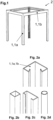
- Fig. 1 shows a spatial representation of a support frame 2 formed from rod profiles 1.
- Some of these rod profiles 1 are essentially vertically aligned and form column elements 1a.
- Another part of the rod profiles 1 are essentially horizontally aligned and form cross beams 1b, which connect the column elements 1a.
- the connections between the column elements 1a and cross beams 1b can be designed as screw connections, for example.
- the support frame 2 has a cube-shaped outer contour overall. However, the invention is not limited to this.
- the support frame 2 can also have a cuboid-shaped outer contour, for example.
- Fig. 2a shows a corner profile
- Fig. 2b a hollow profile with a square cross-section
- Fig. 2c a C-profile
- Fig. 2d a tubular profile.
- the invention is not limited to these profiles.
- U-profiles, L-profiles, Z-profiles, T-profiles, double-T-profiles or hybrids of these can also be used.
- the choice of profile shape ultimately depends on the static requirements of the supporting structure 2.
- a plurality of anchoring points 3 are provided on the column elements 1a and cross beams 1b for receiving anchoring elements 4, whereby these anchoring points 3 are distributed over the length of the column elements 1a and cross beams 1b.
- the anchoring elements 4 can be fixed to the anchoring points 3 in a form-fitting and/or force-fitting manner and detachably.
- the anchoring elements 4 serve to fix a functional element 5 to the supporting structure 2.
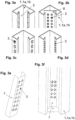
- Fig. 3a to Fig. 3c Various embodiments of the anchoring points 3 on one of the column elements 1a or cross beam 1b are shown according to the invention.
- the starting point is in each case the Fig. 2a Corner profile shown in Fig. 3a
- the anchoring points 3 are designed as hook-shaped recesses on open profile flanks of the corner profile.
- An anchoring element 4 can be hooked into these hook-shaped recesses.
- the anchoring points 3 are designed as openings in a plate element 6.
- the plate element 6 is attached to the open flanks of the corner profile (for example welded).
- Fig. 3c and Fig. 3d each show anchoring points 3 designed as openings in the wall of the corner profile, whereby Fig. 3c keyhole-shaped and Fig. 3d shows openings designed as round holes (not according to the invention).
- FIG. 3e and Fig. 3f Another version is in Fig. 3e and Fig. 3f shown.
- the anchoring points 3 are designed as openings in the wall of a C-profile element 7, whereby these openings are cross-slot-like in the embodiment shown (cf. Fig. 3e
- This C-profile element, which is provided with anchoring points 3, is attached to an inner side of the Fig. 2a shown rod profile (cf. Fig. 3f ).
- the C-profile element is aligned in the rod profile 1, 1a, 1b in such a way that the anchoring points 3 are accessible via the open side of the rod profile 1, 1a, 1b.
- the rigidity of this rod element 1, 1a, 1b and thus of the supporting structure 2 can be further increased by the C-profile element 7 attached to the inside of the rod profile 1, 1a, 1b.
- the invention is not limited to C-profile elements 7 for the formation of the anchoring points 3.
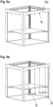
- Fig. 4 shows the supporting structure 2 according to Fig. 1 .
- An anchoring element 4 is fixed to each of the four column elements 1a in an anchoring point 3.
- the four anchoring elements 4 are thus positioned at the same height on the supporting structure 2 and carry a functional element 5 designed as a table top. Due to the large number of anchoring elements along the Thanks to the anchoring points 3 arranged along the length of the column elements 1a, the table top can be positioned at different heights on one and the same support frame 2 as required. The height of the table top can therefore be adjusted accordingly for use as a standing table compared to use as a table for sitting.
- the support frame 2 and the functional element 5 as a whole form a piece of furniture which is characterized by a high degree of flexibility.
- differently shaped functional elements 5 can also be fixed to the support frame 2.
- a functional element designed as a bench can be attached, with two of the anchoring elements 4 holding a seat surface of the bench and two of the anchoring elements 4 holding a seat back of the bench.
- the two anchoring elements 4 attached to the seat back are advantageously fixed to the column elements 1a at a higher position than the anchoring elements 4 attached to the seat surface.
- Fig. 5 shows a detailed representation not according to the invention of one of the anchoring elements 4 of the piece of furniture fixed to an anchoring point 3 from Fig. 4 .
- the anchoring element 4 is designed as a support with connecting straps.
- the anchoring points 3 of the column element 1a shown are designed with round holes, whereby the openings serve to accommodate a screw each, which binds the connecting straps of the anchoring element 4 to the anchoring point 3 in a form-fitting and force-fitting manner.
- the anchoring elements 4 can also be designed as support brackets which are hook-shaped at one end and are hooked with this end into the anchoring points 3 designed as openings.
- the Fig. 3b or Fig. 3e The cross-slot-like openings shown are advantageous because support brackets can be hung in two different (perpendicular to each other) positions.
- Fig. 6a shows another piece of furniture, where the supporting frame 2 is also Fig. 1 serves as a starting point.
- additional anchoring elements 4 designed as eyelets are attached to the anchoring points 3 of the cross beams 1b, which can be used to fix one or more additional functional elements 5 designed as seats.
- four eyelets are provided for each cross beam 1b. Two of these four eyelets can be used to fix a seat held on two rope or chain elements, so that the piece of furniture can have up to eight seats.
- Fig. 6b shows on one of the four cross beams 1b two appropriately secured seats.
- the almost free positioning of the anchoring elements 4 on the cross beams 1b is advantageous. If, for example, a seat held by three rope or chain elements is to be fixed to each cross beam 1b on the same supporting structure, the conditions can be created by repositioning the eyelets accordingly (cf. Fig. 6c ).
- the functional element 5 can also be, for example, a lying surface that is attached to the column elements 1a via anchoring elements 4.
- a lying surface held on rope or chain elements can also be fixed to the crossbeams 1b via anchoring elements 4.
- a functional element 5 designed as a table top, which is held on rope or chain elements can also be fixed to the crossbeams 1b.
- the piece of furniture can be used both indoors and outdoors.
- the piece of furniture can be a communal piece of furniture (e.g. a seating group at a motorway rest area) or a seating group set up in an office.
Landscapes
- Furniture Connections (AREA)
Description
- Die Erfindung betrifft ein Möbelstück mit zumindest einem Funktionselement aufweisend ein aus Stangenprofilen gebildetes Traggerüst, wobei zumindest ein Teil dieser Stangenprofile im Wesentlichen vertikal ausgerichtet sind und Säulenelemente bilden und zumindest ein weiterer Teil der Stangenprofile im Wesentlichen horizontal ausgerichtet sind und die Säulenelemente verbindende Querträger bilden und wobei das Traggerüst Verankerungselemente zur Fixierung des Funktionselementes aufweist.
- Aus dem Stand der Technik sind Möbelstücke bekannt, welche ein aus Stangenprofilen gebildetes Traggerüst aufweisen (beispielsweise
DE 202 09 745 U1 ). Ein Teil dieser Stangenprofile sind dabei im Wesentlichen vertikal ausgerichtet und bilden Säulenelemente. Diese Säulenelemente sind über im Wesentlichen horizontal ausgerichtete Querträger miteinander verbunden. Meist wird damit ein würfel- oder quaderförmiges Traggerüst gebildet. An den Säulenelementen sind festgelegte Verankerungselemente zur Montage von Sitzelementen angebracht. Weiterhin sind auch Traggerüste bekannt, bei denen an den Querträgern Verankerungselemente stoffschlüssig befestigt sind, welche der Fixierung von beispielsweise an Seilen oder Ketten befestigten Sitzelementen dienen. Nachteilig ist aber, dass derartig ausgeführte Möbelstücke nur zur Fixierung eines bestimmten Sitzelementes und damit nur für eine vorbestimmte Funktion nutzbar sind. Durch die festgelegten Verankerungspunkte an den Querträgern ist ein Fixieren eines andersartigen Sitzelementes (beispielsweise Einsitzer anstelle Mehrsitzer) nicht möglich. Auch das Fixieren beispielsweise eines Tischelements anstelle eines Sitzelementes ist nicht möglich. Im Ergebnis muss daher für jede Funktion ein angepasstes Traggerüst vorgesehen werden, was einerseits mit einem hohen Materialaufwand und andererseits beim Nutzer verschiedener Traggerüste mit einem hohen Platzbedarf verbunden ist. - Weiterhin wurde unter https://www.youtube.com/watch?v=mQB072ofi9Q am 02.05.2021 ein Möbelstück, bestehend aus einem Traggerüst mit im Wesentlichen vertikal ausgerichteten Säulenelementen und im Wesentlichen horizontal ausgerichteten Querträgern offenbart. An den Querträgern sind an wenigen Verankerungspunkten fest verbundene Verankerungselemente zur Fixierung von Funktionselementen vorgesehen. Nachteilig ist allerdings, dass durch die fest verbundenen Verankerungselemente an den wenigen Verankerungspunkten nur eine eingeschränkte Fixierung von Funktionselementen möglich ist.
- Aus
US 2019/0082854 A1 ,DE 20 2012 104 355 U1 ,US 2012/0145663 A1 undWO 2003/071898 A2 sind verschiedene Traggerüste bekannt. - Aufgabe der Erfindung ist es daher, ein Möbelstück zu schaffen, welches aus horizontal und vertikal ausgerichteten Stangenprofilen gebildet ist und die Fixierung verschiedenartiger Funktionselemente ermöglicht.
- Diese Aufgabe wird mit einem Möbelstück mit den Merkmalen des Anspruchs 1 bzw. Anspruchs 2 gelöst
- Vorteilhafte Ausgestaltungen sind in den Ansprüchen 3 und 4 hinterlegt. Erfindungsgemäß sind an zumindest einem Teil der Säulenelemente und zumindest einem Teil der Querträger eine Vielzahl über die Länge dieser Säulenelemente und Querträger verteilte Verankerungspunkte zur formschlüssigen und lösbaren Aufnahme von Verankerungselementen an diesen Säulenelementen und Querträgern vorgesehen. Durch die Vielzahl der Verankerungspunkte sind die Verankerungselemente flexibel über die Länge zumindest eines Teils der Säulenelemente und Querträger positionierbar. Somit kann die Position der Verankerungselemente zur Fixierung eines Funktionselements auf die Erfordernisse des jeweiligen Funktionselements angepasst werden. An dem Traggerüst können damit beliebige Funktionselemente fixiert werden, sodass das Möbelstück mit ein und demselben Traggerüst grundsätzlich vielfältige Funktionen erfüllen kann.
- Nachfolgend wird ein Ausführungsbeispiel der Erfindung anhand der Zeichnungen erläutert.
- Es zeigen
- Fig. 1
- eine räumliche Darstellung eines aus Stangenprofilen gebildeten Traggerüstes
- Fig. 2a - d
- schematische Darstellungen der Stangenprofile
- Fig. 3a - c und e-f
- Ausführungen der Verankerungspunkte
- Fig. 3d
- nicht erfindungsgemäßes Beispiel der Verankerungspunkte
- Fig. 4
- Traggerüst mit als Tischplatte ausgestaltetem Funktionselement
- Fig. 5
- Detaildarstellung eines nicht erfindungsgemäßen am Verankerungspunkt fixierten Verankerungselementes
- Fig. 6a - c
- Traggerüst mit verschiedenen Ausführungen der Funktionselemente
-
Fig. 1 zeigt eine räumliche Darstellung eines aus Stangenprofilen 1 gebildeten Traggerüstes 2. Ein Teil dieser Stangenprofile 1 sind im Wesentlichen vertikal ausgerichtet und bilden Säulenelemente 1a. Ein weiterer Teil der Stangenprofile 1 sind im Wesentlichen horizontal ausgerichtet und bilden Querträger 1b, welche die Säulenelemente 1a verbinden. Die Verbindungen zwischen den Säulenelementen 1a und Querträgern 1b können beispielsweise als Schraubverbindung ausgeführt sein. Das Traggerüst 2 weist insgesamt eine würfelförmige Außenkontur auf. Die Erfindung ist aber nicht hierauf beschränkt. Das Traggerüst 2 kann beispielsweise auch eine quaderförmige Außenkontur aufweisen. - In den
Fig. 2a bis Fig. 2d sind beispielhafte Ausführungen der Stangenprofile 1a und Querträger 1b ohne die Verankerungspunkte dargestellt.Fig. 2a zeigt ein Eckprofil,Fig. 2b ein Hohlprofil mit quadratischem Querschnitt,Fig. 2c ein C-Profil undFig. 2d ein Rohrprofil. Die Erfindung ist allerdings nicht auf diese Profile beschränkt. Beispielsweise können auch U-Profile, L-Profile, Z-Profile, T-Profile, Doppel-T-Profile oder Mischformen hieraus genutzt werden. Die Wahl der Profilform richtet sich letztlich nach den statischen Anforderungen an das Traggerüst 2. - An den Säulenelementen 1a und Querträgern 1b sind eine Vielzahl an Verankerungspunkten 3 zur Aufnahme von Verankerungselementen 4 vorgesehen, wobei diese Verankerungspunkte 3 über die Länge der Säulenelemente 1a und Querträger 1b verteilt sind. Die Verankerungselemente 4 können formschlüssig und/oder kraftschlüssig sowie lösbar an den Verankerungspunkten 3 fixiert werden. Die Verankerungselemente 4 dienen der Fixierung eines Funktionselementes 5 an dem Traggerüst 2.
- In den
Fig. 3a bis Fig. 3c sind verschiedene erfindungsgemäße Ausführungen der Verankerungspunkte 3 an einem der Säulenelemente 1a bzw. Querträger 1b gezeigt. Ausgangspunkt ist jeweils das inFig. 2a dargestellte Eckprofil. Bei der inFig. 3a gezeigten Variante sind die Verankerungspunkte 3 als hakenförmige Ausnehmungen an offenen Profilflanken des Eckprofils ausgebildet. In diese hakenförmigen Ausnehmungen ist ein Verankerungselement 4 einhängbar. GemäßFig. 3b sind die Verankerungspunkte 3 als Öffnungen in einem Plattenelement 6 ausgeführt. Das Plattenelement 6 ist an den offenen Flanken des Eckprofils befestigt (beispielsweise angeschweißt). - Die Darstellungen in
Fig. 3c und Fig. 3d zeigen jeweils als Öffnungen in der Wandung des Eckprofils ausgestaltete Verankerungspunkte 3, wobeiFig. 3c schlüssellochförmig undFig. 3d als Rundloch (nicht erfindungsgemäß) ausgebildete Öffnungen zeigt. - Eine weitere Ausführung ist in
Fig. 3e und Fig. 3f gezeigt. Die Verankerungspunkte 3 sind als Öffnungen in der Wandung eines C-Profilelementes 7 ausgebildet, wobei diese Öffnungen in der dargestellten Ausführung kreuzschlitzartig sind (vgl.Fig. 3e ). Dieses mit Verankerungspunkten 3 versehene C-Profilelement ist an einer Innenseite des inFig. 2a dargestellten Stangenprofils befestigt (vgl.Fig. 3f ). Das C-Profilelement ist dabei so in dem Stangenprofil 1, 1a, 1b ausgerichtet, dass die Verankerungspunkte 3 über die offene Seite des Stangenprofils 1, 1a, 1b zugänglich sind. Durch das an der Innenseite des Stangenprofils 1, 1a, 1b befestigte C-Profilelement 7 kann die Steifigkeit dieses Stangenelementes 1, 1a, 1b und damit des Traggerüsts 2 weiter erhöht. Die Erfindung ist aber auch hier zur Ausbildung der Verankerungspunkte 3 nicht auf C-Profilelemente 7 beschränkt. -
Fig. 4 zeigt das Traggerüst 2 gemäßFig. 1 . An den vier Säulenelementen 1a ist jeweils ein Verankerungselement 4 in je einem Verankerungspunkt 3 fixiert. Die vier Verankerungselemente 4 werden damit in derselben Höhe am Traggerüst 2 positioniert und tragen ein als Tischplatte ausgestaltetes Funktionselement 5. Durch die Vielzahl entlang der Länge der Säulenelemente 1a angeordneten Verankerungspunkte 3 kann die Tischplatte je nach Anforderung an ein und demselben Traggerüst 2 in verschiedenen Höhen positioniert werden. Somit kann die Höhe der Tischplatte zur Verwendung als Stehtisch gegenüber einer Verwendung als Tisch zum Sitzen entsprechend angepasst werden. Das Traggerüst 2 und das Funktionselement 5 bilden in ihrer Gesamtheit ein Möbelstück, welches sich durch eine hohe Flexibilität auszeichnet. Durch eine Umpositionierung der Verankerungselemente 4 an den Säulenelementen 1a können auch anders geformte Funktionselemente 5 an dem Traggerüst 2 fixiert werden. Beispielsweise kann ein als Sitzbank ausgestaltetes Funktionselement befestigt werden, wobei hierzu zwei der Verankerungselemente 4 eine Sitzfläche der Sitzbank und zwei der Verankerungselemente 4 eine Sitzlehne der Sitzbank halten. Vorteilhafterweise sind die beiden an der Sitzlehne befestigten Verankerungselemente 4 an einer höheren Position als die an der Sitzfläche befestigten Verankerungselemente 4 an den Säulenelementen 1a fixiert. -
Fig. 5 zeigt eine nicht erfindungsgemäße Detaildarstellung eines der an einem Verankerungspunkt 3 fixierten Verankerungselemente 4 des Möbelstücks ausFig. 4 . Das Verankerungselement 4 ist als Träger mit Verbindungslaschen ausgestaltet. Die Verankerungspunkte 3 des gezeigten Säulenelementes 1a sind mit Rundlöchern ausgeführt, wobei die Öffnungen zur Aufnahme je einer Schraube dienen, welche die Verbindungslaschen des Verankerungselementes 4 form- und kraftschlüssig an den Verankerungspunkt 3 bindet. - Die Erfindung ist nicht auf die dargestellte Ausführung der Verankerungselemente 4 beschränkt. Beispielsweise können die Verankerungselemente 4 auch als Trägerkonsolen ausgeführt sein, die an einem Ende hakenförmig ausgebildet sind und mit diesem Ende in die als Öffnungen ausgestalteten Verankerungspunkte 3 eingehängt werden. Hierbei erweisen sich die in
Fig. 3b oder Fig. 3e gezeigten kreuzschlitzartigen Öffnungen vorteilhaft, da Trägerkonsolen hier in zwei verschiedenen (zueinander rechtwinkligen) Positionen eingehängt werden können. -
Fig. 6a zeigt ein weiteres Möbelstück, wobei auch hier das Traggerüst 2 gemäßFig. 1 als Ausgangspunkt dient. Neben der bereits inFig. 5 gezeigten Tischplatte sind hier weitere als Ösen ausgeführte Verankerungselemente 4 in den Verankerungspunkten 3 der Querträger 1b befestigt, die zur Fixierung einer oder mehrerer als Sitzflächen ausgestalteter weiterer Funktionselemente 5 genutzt werden können. In der dargestellten Ausführung sind je Querträger 1b vier Ösen vorgesehen. Je zwei dieser vier Ösen können zur Fixierung einer an zwei Seil- oder Kettenelementen gehaltenen Sitzfläche dienen, sodass das Möbelstück dabei bis zu acht Sitzflächen aufweisen kann.Fig. 6b zeigt an einem der vier Querträger 1b zwei entsprechend befestigte Sitzflächen. Auch hier ist die nahezu freie Positionierbarkeit der Verankerungselemente 4 an den Querträgern 1b vorteilhaft. Soll an demselben Traggerüst beispielsweise an jedem Querträger 1b eine an drei Seil- oder Kettenelementen gehaltene Sitzfläche fixiert werden, können durch entsprechende Umpositionierung der Ösen die Voraussetzungen geschaffen werden (vgl.Fig. 6c ). - In weiteren nicht dargestellten Ausführungen kann das Funktionselement 5 beispielsweise auch eine Liegefläche sein, die über Verankerungselemente 4 an den Säulenelementen 1a befestigt ist. Ebenso kann auch eine an Seil- oder Kettenelementen gehaltene Liegefläche über Verankerungselemente 4 an den Querträgern 1b fixiert sein. Weiterhin kann auch ein als Tischplatte ausgeführtes Funktionselement 5, welches an Seil- oder Kettenelementen gehalten wird, an den Querträgern 1b fixiert werden.
- Das Möbelstück kann sowohl im Indoorbereich, als auch im Outdoorbereich genutzt. Beispielsweise kann das Möbelstück ein Kommunalmöbelstück (beispielsweise Sitzgruppe auf Autobahnrastplatz) oder eine in einem Büro aufgestellte Sitzgruppe sein.
-
- 1
- Stangenprofil
- 1a
- Säulenelement
- 1b
- Querträger
- 2
- Traggerüst
- 3
- Verankerungspunkt
- 4
- Verankerungselement
- 5
- Funktionselement
- 6
- Plattenelement
- 7
- Profilelement
Claims (4)
- Möbelstück mit zumindest einem Funktionselement (5), aufweisend ein aus Stangenprofilen (1) gebildetes Traggerüst (2), wobei zumindest ein Teil dieser Stangenprofile (1) im Wesentlichen vertikal ausgerichtet sind und Säulenelemente (1a) bilden und zumindest ein weiterer Teil der Stangenprofile (1) im Wesentlichen horizontal ausgerichtet sind und die Säulenelemente (1a) verbindende Querträger (1b) bilden und wobei das Traggerüst (2) Verankerungselemente (4) zur Fixierung des Funktionselementes (5) aufweist, wobei zumindest ein Teil der Säulenelemente (1a) und zumindest ein Teil der Querträger (1b) eine Vielzahl über die Länge dieser Säulenelemente (1a) und Querträger (1b) verteilte Verankerungspunkte (3) zur formschlüssigen und/oder kraftschlüssigen sowie lösbaren Befestigung der Verankerungselemente (4) an diesen Säulenelementen (1a) und Querträgern (1b) aufweist und wobei das Funktionselement (5) eine Tischplatte oder eine Liegefläche oder eine Sitzfläche ist und diese Tischplatte oder Liegefläche oder Sitzfläche über die Verankerungselemente (4) an den Säulenelementen (1a) abgestützt oder über Seil-oder Kettenelemente mit den Verankerungselementen (4) an den Querträgern (1b) befestigt ist, wobei die Säulenelemente (1a) und die Querträger (1b) als Rohre oder Hohlprofile oder C-Profile oder U-Profile oder L-Profile oder Z-Profile oder T-Profile oder Doppel-T-Profile ausgebildet sind und wobei die Verankerungspunkte (3) zur Aufnahme der Verankerungselemente (4) als Öffnungen in den Wandungen der Rohre oder Hohlprofile oder C-Profile oder U-Profile oder L-Profile oder Z-Profile oder T-Profile oder Doppel-T-Profile ausgeführt sind und wobei die Öffnungen schlüssellochförmig oder kreuzschlitzartig ausgeführt sind.
- Möbelstück mit zumindest einem Funktionselement (5), aufweisend ein aus Stangenprofilen (1) gebildetes Traggerüst (2), wobei zumindest ein Teil dieser Stangenprofile (1) im Wesentlichen vertikal ausgerichtet sind und Säulenelemente (1a) bilden und zumindest ein weiterer Teil der Stangenprofile (1) im Wesentlichen horizontal ausgerichtet sind und die Säulenelemente (1a) verbindende Querträger (1b) bilden und wobei das Traggerüst (2) Verankerungselemente (4) zur Fixierung des Funktionselementes (5) aufweist, wobei zumindest ein Teil der Säulenelemente (1a) und zumindest ein Teil der Querträger (1b) eine Vielzahl über die Länge dieser Säulenelemente (1a) und Querträger (1b) verteilte Verankerungspunkte (3) zur formschlüssigen und/oder kraftschlüssigen sowie lösbaren Befestigung der Verankerungselemente (4) an diesen Säulenelementen (1a) und Querträgern (1b) aufweist und wobei das Funktionselement (5) eine Tischplatte oder eine Liegefläche oder eine Sitzfläche ist und diese Tischplatte oder Liegefläche oder Sitzfläche über die Verankerungselemente (4) an den Säulenelementen (1a) abgestützt oder über Seil-oder Kettenelemente mit den Verankerungselementen (4) an den Querträgern (1b) befestigt ist, wobei die Säulenelemente (1a) und die Querträger (1b) als Rohre oder Hohlprofile oder C-Profile oder U-Profile oder L-Profile oder Z-Profile oder T-Profile oder Doppel-T-Profile ausgebildet sind und wobei die Verankerungspunkte (3) zur Aufnahme der Verankerungselemente (4) als hakenförmige Ausnehmungen an offenen Profilflanken der C-Profile oder U-Profile oder L-Profile oder Z-Profile oder T-Profile oder Doppel-T-Profile ausgebildet sind.
- Möbelstück nach einem der vorgenannten Ansprüche, dadurch gekennzeichnet, dass das Traggerüst (2) eine würfelförmige oder quaderförmige Außenkontur aufweist.
- Möbelstück nach einem der vorgenannten Ansprüche, dadurch gekennzeichnet, dass das Möbelstück ein Indoormöbelstück oder ein Outdoormöbelstück oder ein Kommunalmöbelstück ist.
Applications Claiming Priority (1)
| Application Number | Priority Date | Filing Date | Title |
|---|---|---|---|
| DE102021115129.5A DE102021115129A1 (de) | 2021-06-11 | 2021-06-11 | Möbelstück |
Publications (2)
| Publication Number | Publication Date |
|---|---|
| EP4101340A1 EP4101340A1 (de) | 2022-12-14 |
| EP4101340B1 true EP4101340B1 (de) | 2024-10-16 |
Family
ID=81984695
Family Applications (1)
| Application Number | Title | Priority Date | Filing Date |
|---|---|---|---|
| EP22177693.3A Active EP4101340B1 (de) | 2021-06-11 | 2022-06-07 | Möbelstück |
Country Status (2)
| Country | Link |
|---|---|
| EP (1) | EP4101340B1 (de) |
| DE (1) | DE102021115129A1 (de) |
Family Cites Families (6)
| Publication number | Priority date | Publication date | Assignee | Title |
|---|---|---|---|---|
| AU2003217619A1 (en) * | 2002-02-21 | 2003-09-09 | Engel Zackary | Shelving system |
| DE20209745U1 (de) | 2002-06-24 | 2003-01-02 | Keller, Sergej, 51067 Köln | Garten-, Camping- und Terrassenhaus |
| US8851300B2 (en) * | 2010-12-13 | 2014-10-07 | Proper Storage Systems, LLC | Roll-out shelving storage rack system |
| DE202012104355U1 (de) * | 2012-11-12 | 2012-11-22 | Ching-Chen Hsieh | Verbesserter Aufbau eines Gestells |
| DE102014109028A1 (de) | 2013-06-27 | 2014-12-31 | Messestahl GmbH | Verbindungselement für ein transportables Tragwerk und transportables Tragwerk |
| US10806269B2 (en) * | 2017-09-21 | 2020-10-20 | Sauder Manufacturing Co. | Adjustable furniture track system |
-
2021
- 2021-06-11 DE DE102021115129.5A patent/DE102021115129A1/de active Pending
-
2022
- 2022-06-07 EP EP22177693.3A patent/EP4101340B1/de active Active
Also Published As
| Publication number | Publication date |
|---|---|
| EP4101340A1 (de) | 2022-12-14 |
| DE102021115129A1 (de) | 2022-12-15 |
Similar Documents
| Publication | Publication Date | Title |
|---|---|---|
| DE10111314C1 (de) | Traggestell | |
| DE1554003A1 (de) | Mehrsitziges Gestuehl | |
| EP2455305B1 (de) | Silo | |
| EP4101340B1 (de) | Möbelstück | |
| EP0860559B1 (de) | Anordnung mit einer Installationswand aus Profilstangen, insbesondere Installationswand für Sanitärapparate | |
| WO2021105197A1 (de) | Möbelbausatz | |
| EP4173476B1 (de) | Hochbeet mit seitenwänden und querstreben | |
| DE9312108U1 (de) | Metall-Skelett für den Endausbau zu einem begehbaren Mehrzweck-Container | |
| DE29622396U1 (de) | Regal | |
| DE102011115535B4 (de) | Modulares Stützgerüst | |
| EP4258947A1 (de) | Kragarmregal | |
| DE10115841A1 (de) | Systemträger | |
| DE202019101127U1 (de) | Modulares Möbel | |
| DE102023113615B3 (de) | Aufnahmetrog zum Bepflanzen | |
| DE102022114668B4 (de) | Bewehrungsvorrichtung | |
| EP2358592A2 (de) | Skelett für eine fluggastsitzreihe | |
| DE2721077C3 (de) | Kücheneinrichtung aus vorgefertigten Elementen | |
| AT523445B1 (de) | Etagenbeet | |
| DE19526281C1 (de) | Aussteifungselement für Regale | |
| EP0517938A1 (de) | Modulares Einrichtungssystem | |
| DE2709868A1 (de) | Regalanordnung | |
| AT526675A4 (de) | Fahrzeugunterstand | |
| DE29710038U1 (de) | Tisch | |
| EP2368461B1 (de) | Sitzmöbel | |
| DE20017735U1 (de) | Schranksystem insbesondere für Büros |
Legal Events
| Date | Code | Title | Description |
|---|---|---|---|
| PUAI | Public reference made under article 153(3) epc to a published international application that has entered the european phase |
Free format text: ORIGINAL CODE: 0009012 |
|
| STAA | Information on the status of an ep patent application or granted ep patent |
Free format text: STATUS: THE APPLICATION HAS BEEN PUBLISHED |
|
| AK | Designated contracting states |
Kind code of ref document: A1 Designated state(s): AL AT BE BG CH CY CZ DE DK EE ES FI FR GB GR HR HU IE IS IT LI LT LU LV MC MK MT NL NO PL PT RO RS SE SI SK SM TR |
|
| RAP1 | Party data changed (applicant data changed or rights of an application transferred) |
Owner name: SKERSIES, LISA KATHRIN REGINE |
|
| RIN1 | Information on inventor provided before grant (corrected) |
Inventor name: SKERSIES, CARSTEN |
|
| STAA | Information on the status of an ep patent application or granted ep patent |
Free format text: STATUS: REQUEST FOR EXAMINATION WAS MADE |
|
| 17P | Request for examination filed |
Effective date: 20230607 |
|
| RBV | Designated contracting states (corrected) |
Designated state(s): AL AT BE BG CH CY CZ DE DK EE ES FI FR GB GR HR HU IE IS IT LI LT LU LV MC MK MT NL NO PL PT RO RS SE SI SK SM TR |
|
| GRAP | Despatch of communication of intention to grant a patent |
Free format text: ORIGINAL CODE: EPIDOSNIGR1 |
|
| STAA | Information on the status of an ep patent application or granted ep patent |
Free format text: STATUS: GRANT OF PATENT IS INTENDED |
|
| INTG | Intention to grant announced |
Effective date: 20240507 |
|
| GRAS | Grant fee paid |
Free format text: ORIGINAL CODE: EPIDOSNIGR3 |
|
| GRAA | (expected) grant |
Free format text: ORIGINAL CODE: 0009210 |
|
| STAA | Information on the status of an ep patent application or granted ep patent |
Free format text: STATUS: THE PATENT HAS BEEN GRANTED |
|
| AK | Designated contracting states |
Kind code of ref document: B1 Designated state(s): AL AT BE BG CH CY CZ DE DK EE ES FI FR GB GR HR HU IE IS IT LI LT LU LV MC MK MT NL NO PL PT RO RS SE SI SK SM TR |
|
| REG | Reference to a national code |
Ref country code: GB Ref legal event code: FG4D Free format text: NOT ENGLISH |
|
| REG | Reference to a national code |
Ref country code: CH Ref legal event code: EP |
|
| REG | Reference to a national code |
Ref country code: IE Ref legal event code: FG4D Free format text: LANGUAGE OF EP DOCUMENT: GERMAN |
|
| REG | Reference to a national code |
Ref country code: DE Ref legal event code: R096 Ref document number: 502022001891 Country of ref document: DE |
|
| REG | Reference to a national code |
Ref country code: LT Ref legal event code: MG9D |
|
| RAP4 | Party data changed (patent owner data changed or rights of a patent transferred) |
Owner name: SKERSIES, LISA KATHRIN REGINE |
|
| REG | Reference to a national code |
Ref country code: NL Ref legal event code: MP Effective date: 20241016 |
|
| REG | Reference to a national code |
Ref country code: DE Ref legal event code: R081 Ref document number: 502022001891 Country of ref document: DE Owner name: SKERSIES, LISA KATHRIN REGINE, DE Free format text: FORMER OWNER: SKERSIES, LISA KATHRIN REGINE, 20535 HAMBURG, DE |
|
| PG25 | Lapsed in a contracting state [announced via postgrant information from national office to epo] |
Ref country code: NL Free format text: LAPSE BECAUSE OF FAILURE TO SUBMIT A TRANSLATION OF THE DESCRIPTION OR TO PAY THE FEE WITHIN THE PRESCRIBED TIME-LIMIT Effective date: 20241016 |
|
| PG25 | Lapsed in a contracting state [announced via postgrant information from national office to epo] |
Ref country code: NL Free format text: LAPSE BECAUSE OF FAILURE TO SUBMIT A TRANSLATION OF THE DESCRIPTION OR TO PAY THE FEE WITHIN THE PRESCRIBED TIME-LIMIT Effective date: 20241016 |
|
| PG25 | Lapsed in a contracting state [announced via postgrant information from national office to epo] |
Ref country code: IS Free format text: LAPSE BECAUSE OF FAILURE TO SUBMIT A TRANSLATION OF THE DESCRIPTION OR TO PAY THE FEE WITHIN THE PRESCRIBED TIME-LIMIT Effective date: 20250216 Ref country code: HR Free format text: LAPSE BECAUSE OF FAILURE TO SUBMIT A TRANSLATION OF THE DESCRIPTION OR TO PAY THE FEE WITHIN THE PRESCRIBED TIME-LIMIT Effective date: 20241016 Ref country code: PT Free format text: LAPSE BECAUSE OF FAILURE TO SUBMIT A TRANSLATION OF THE DESCRIPTION OR TO PAY THE FEE WITHIN THE PRESCRIBED TIME-LIMIT Effective date: 20250217 |
|
| PG25 | Lapsed in a contracting state [announced via postgrant information from national office to epo] |
Ref country code: FI Free format text: LAPSE BECAUSE OF FAILURE TO SUBMIT A TRANSLATION OF THE DESCRIPTION OR TO PAY THE FEE WITHIN THE PRESCRIBED TIME-LIMIT Effective date: 20241016 |
|
| PG25 | Lapsed in a contracting state [announced via postgrant information from national office to epo] |
Ref country code: BG Free format text: LAPSE BECAUSE OF FAILURE TO SUBMIT A TRANSLATION OF THE DESCRIPTION OR TO PAY THE FEE WITHIN THE PRESCRIBED TIME-LIMIT Effective date: 20241016 |
|
| PG25 | Lapsed in a contracting state [announced via postgrant information from national office to epo] |
Ref country code: ES Free format text: LAPSE BECAUSE OF FAILURE TO SUBMIT A TRANSLATION OF THE DESCRIPTION OR TO PAY THE FEE WITHIN THE PRESCRIBED TIME-LIMIT Effective date: 20241016 |
|
| PG25 | Lapsed in a contracting state [announced via postgrant information from national office to epo] |
Ref country code: NO Free format text: LAPSE BECAUSE OF FAILURE TO SUBMIT A TRANSLATION OF THE DESCRIPTION OR TO PAY THE FEE WITHIN THE PRESCRIBED TIME-LIMIT Effective date: 20250116 |
|
| PG25 | Lapsed in a contracting state [announced via postgrant information from national office to epo] |
Ref country code: LV Free format text: LAPSE BECAUSE OF FAILURE TO SUBMIT A TRANSLATION OF THE DESCRIPTION OR TO PAY THE FEE WITHIN THE PRESCRIBED TIME-LIMIT Effective date: 20241016 Ref country code: GR Free format text: LAPSE BECAUSE OF FAILURE TO SUBMIT A TRANSLATION OF THE DESCRIPTION OR TO PAY THE FEE WITHIN THE PRESCRIBED TIME-LIMIT Effective date: 20250117 |
|
| PG25 | Lapsed in a contracting state [announced via postgrant information from national office to epo] |
Ref country code: PL Free format text: LAPSE BECAUSE OF FAILURE TO SUBMIT A TRANSLATION OF THE DESCRIPTION OR TO PAY THE FEE WITHIN THE PRESCRIBED TIME-LIMIT Effective date: 20241016 |
|
| PG25 | Lapsed in a contracting state [announced via postgrant information from national office to epo] |
Ref country code: RS Free format text: LAPSE BECAUSE OF FAILURE TO SUBMIT A TRANSLATION OF THE DESCRIPTION OR TO PAY THE FEE WITHIN THE PRESCRIBED TIME-LIMIT Effective date: 20250116 |
|
| PG25 | Lapsed in a contracting state [announced via postgrant information from national office to epo] |
Ref country code: SM Free format text: LAPSE BECAUSE OF FAILURE TO SUBMIT A TRANSLATION OF THE DESCRIPTION OR TO PAY THE FEE WITHIN THE PRESCRIBED TIME-LIMIT Effective date: 20241016 |
|
| PG25 | Lapsed in a contracting state [announced via postgrant information from national office to epo] |
Ref country code: DK Free format text: LAPSE BECAUSE OF FAILURE TO SUBMIT A TRANSLATION OF THE DESCRIPTION OR TO PAY THE FEE WITHIN THE PRESCRIBED TIME-LIMIT Effective date: 20241016 |
|
| REG | Reference to a national code |
Ref country code: DE Ref legal event code: R097 Ref document number: 502022001891 Country of ref document: DE |
|
| PG25 | Lapsed in a contracting state [announced via postgrant information from national office to epo] |
Ref country code: EE Free format text: LAPSE BECAUSE OF FAILURE TO SUBMIT A TRANSLATION OF THE DESCRIPTION OR TO PAY THE FEE WITHIN THE PRESCRIBED TIME-LIMIT Effective date: 20241016 |
|
| PG25 | Lapsed in a contracting state [announced via postgrant information from national office to epo] |
Ref country code: RO Free format text: LAPSE BECAUSE OF FAILURE TO SUBMIT A TRANSLATION OF THE DESCRIPTION OR TO PAY THE FEE WITHIN THE PRESCRIBED TIME-LIMIT Effective date: 20241016 |
|
| PGFP | Annual fee paid to national office [announced via postgrant information from national office to epo] |
Ref country code: AT Payment date: 20250721 Year of fee payment: 4 |
|
| PG25 | Lapsed in a contracting state [announced via postgrant information from national office to epo] |
Ref country code: SK Free format text: LAPSE BECAUSE OF FAILURE TO SUBMIT A TRANSLATION OF THE DESCRIPTION OR TO PAY THE FEE WITHIN THE PRESCRIBED TIME-LIMIT Effective date: 20241016 |
|
| PG25 | Lapsed in a contracting state [announced via postgrant information from national office to epo] |
Ref country code: CZ Free format text: LAPSE BECAUSE OF FAILURE TO SUBMIT A TRANSLATION OF THE DESCRIPTION OR TO PAY THE FEE WITHIN THE PRESCRIBED TIME-LIMIT Effective date: 20241016 |
|
| PG25 | Lapsed in a contracting state [announced via postgrant information from national office to epo] |
Ref country code: IT Free format text: LAPSE BECAUSE OF FAILURE TO SUBMIT A TRANSLATION OF THE DESCRIPTION OR TO PAY THE FEE WITHIN THE PRESCRIBED TIME-LIMIT Effective date: 20241016 |
|
| PLBE | No opposition filed within time limit |
Free format text: ORIGINAL CODE: 0009261 |
|
| STAA | Information on the status of an ep patent application or granted ep patent |
Free format text: STATUS: NO OPPOSITION FILED WITHIN TIME LIMIT |
|
| PG25 | Lapsed in a contracting state [announced via postgrant information from national office to epo] |
Ref country code: SE Free format text: LAPSE BECAUSE OF FAILURE TO SUBMIT A TRANSLATION OF THE DESCRIPTION OR TO PAY THE FEE WITHIN THE PRESCRIBED TIME-LIMIT Effective date: 20241016 |
|
| 26N | No opposition filed |
Effective date: 20250717 |
|
| PGFP | Annual fee paid to national office [announced via postgrant information from national office to epo] |
Ref country code: DE Payment date: 20250815 Year of fee payment: 4 |
|
| PGFP | Annual fee paid to national office [announced via postgrant information from national office to epo] |
Ref country code: CH Payment date: 20250724 Year of fee payment: 4 |
|
| PG25 | Lapsed in a contracting state [announced via postgrant information from national office to epo] |
Ref country code: MC Free format text: LAPSE BECAUSE OF FAILURE TO SUBMIT A TRANSLATION OF THE DESCRIPTION OR TO PAY THE FEE WITHIN THE PRESCRIBED TIME-LIMIT Effective date: 20241016 |