EP4101337B1 - Verschlussanordnung für einen schmuckgegenstand wie ein armband - Google Patents
Verschlussanordnung für einen schmuckgegenstand wie ein armband Download PDFInfo
- Publication number
- EP4101337B1 EP4101337B1 EP22177744.4A EP22177744A EP4101337B1 EP 4101337 B1 EP4101337 B1 EP 4101337B1 EP 22177744 A EP22177744 A EP 22177744A EP 4101337 B1 EP4101337 B1 EP 4101337B1
- Authority
- EP
- European Patent Office
- Prior art keywords
- base part
- locking
- lock assembly
- assembly according
- aperture
- Prior art date
- Legal status (The legal status is an assumption and is not a legal conclusion. Google has not performed a legal analysis and makes no representation as to the accuracy of the status listed.)
- Active
Links
Images

Classifications
-
- A—HUMAN NECESSITIES
- A44—HABERDASHERY; JEWELLERY
- A44C—PERSONAL ADORNMENTS, e.g. JEWELLERY; COINS
- A44C5/00—Bracelets; Wrist-watch straps; Fastenings for bracelets or wrist-watch straps
- A44C5/18—Fasteners for straps, chains or the like
- A44C5/20—Fasteners for straps, chains or the like for open straps, chains or the like
- A44C5/2085—Fasteners for straps, chains or the like for open straps, chains or the like with the two ends sliding transversally to the main plane of the strap or chain
Definitions
- the present invention relates to a lock assembly for an article of jewellery having two free ends to be connected to each other, such as a bracelet, necklace, etc.
- the locking device for connecting two end loops of a jewellery strand such as a bracelet or necklace.
- the locking device comprises a strand retainer with retainer loops for engaging with the jewellery strands, and a separate clip member having two half shells hinged together and snap lockable for forming a through hole.
- the present invention seeks to provide an improved lock assembly for a bracelet or necklace, which is lockable once and easy to apply using a single hand.
- a locking assembly as defined above is provided, comprising a first base part and a second base part, the first base part and/or second base part comprising a first end attachment part and a second end attachment part. Furthermore, a pivotal connection assembly is present for pivotally connecting the first base part and the second base part, comprising a pivot pin extending substantially perpendicular from a major surface of one of the first and second base part, and a pivot aperture in the other one of the first and second base part, a diameter of the pivot pin and a diameter of the pivot aperture being substantially equal.
- a fixation assembly for locking the first base part and second base part in a fixed mutual position, comprising a locking extension on a major surface of one of the first and second base part, and a locking aperture in a major surface of the other one of the first and second base part, a diameter of the locking extension being equal to or larger than a diameter of the locking aperture.
- Such a locking assembly having both a pivotal connection assembly, and a fixation assembly allows to operate the lock assembly with a single hand, to connect and fix the two free ends of the article of jewellery.
- Articles of jewellery such as bracelets, necklaces and the like, are often in the form of a chain, band or chord, with two open ends which are connected together using a locking assembly.
- the present invention embodiments are directed at a locking assembly for an article of jewellery, which can be handled and operated using only a single hand, which is especially advantageous for connecting together ends of a bracelet.
- the present invention embodiments are arranged to be able to be locked only once, after which the bracelet or necklace can only be unlocked by forced opening, destroying the locking assembly.
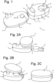
- Fig. 1 shows a perspective view of two base parts 2, 3 of a locking assembly 1 according to an exemplary embodiment of the present invention.
- the locking assembly 1 may be used for an article of jewellery having two free ends to be connected to each other, such as a bracelet, necklace, etc. and comprises a first base part 2 shown in Fig. 1 having a thickness t1 and a second base part 3 shown in Fig. 1 having a thickness t2.
- the first base part 2 and/or second base part 3 comprise a first end attachment part 4 and a second end attachment part 5 for attaching the two free ends of the article of jewellery.
- the second base part 3 comprises both the first and second end attachment parts 4, 5.
- the locking assembly 1 further comprises a pivotal connection assembly 6 for pivotally connecting the first base part 2 and the second base part 3.
- the pivotal connection assembly 6 comprises a pivot pin 7 extending substantially perpendicular from a major surface of one of the first and second base part 2; 3, and a pivot aperture 8 in the other one of the first and second base part 3; 2.
- the pivot pin 7 is provided as part of the first base part 2, having a height h1, and the pivot aperture 8 is provided as part of the second base part 3.
- a diameter of the pivot pin 7 and a diameter of the pivot aperture 8 are substantially equal, allowing mutual rotation of the first base part 2 with respect to the second base part 3.
- the diameters of pivot pin 7 and pivot aperture are e.g. in the order of magnitude of 0.5mm.
- the locking assembly 1 comprises a fixation assembly 9 for locking the first base part 2 and second base part 3 in a fixed mutual position.
- the fixation locking assembly 9 comprises a locking extension 10 on a major surface of one of the first and second base part 2; 3, and a locking aperture 11 in a major surface of the other one of the first and second base part 3; 2.
- the locking extension 10 is provided as a rounded column on the major surface of first base part 1, having a height h2.
- a diameter of the locking extension 10 is equal to or (slightly) larger than a diameter of the locking aperture 11, which allows to lock the first and second base part 2, 3 together by pressing.
- first base part 2 and the second base part 3 are congruent, with both having a corresponding major surface, and a congruent outer shape, in this example a rectangle with rounded corners.
- different shapes of the first base part 2 and/or second base part 3 are possible, such as a square, triangular, round, ellipsoid, multi-angular shape, etc.
- the first end attachment part 4 is arranged for fixed connection of one of the free ends of the article of jewellery in a further embodiment.
- the first end attachment part 4 is a cavity provided in a side surface of the second base part 3, allowing to connect the free end e.g. using (laser) welding, soldering, gluing, knotting, or other connection techniques.
- the second end attachment part 5 comprises a cavity 15 in a major surface of one of the first and second base part 2; 3 with an external access aperture 16 in a further embodiment.
- the cavity 15 is accessible for the other one of the free ends of the article of jewellery when the first base part 2 and second base part 3 are pivoted into an initial non-locked position.
- the cavity 15 is circular shaped, and the external access aperture 16 is provided in a side wall of the second base part 3, opposite to the first end attachment part 4.
- the cavity 15 may be rectangular, e.g. square.
- Fig. 2A-C each show a perspective view of a locking assembly according to an embodiment of the present invention in subsequent locking steps
- Fig. 3A-C each show a further perspective view of the locking assembly embodiment of Fig. 2 in the subsequent locking steps from the other side.
- the one of the free ends of the article of jewellery comprises an end body 17 having a shape congruent with the cavity 15, e.g. having a circular shape congruent with a circular cavity 15 or having a rectangular shape congruent with a rectangular cavity 15.
- the locking assembly 1 to be provided as a part of an article of jewellery having two free ends to be connected to each other, with one of the free ends attached to the first end attachment part 4 and the second end connected to the end body 17.
- the first body part 2 and second body part 3 (with one of the ends of the article of jewellery attached) are pivotally connected by having the pivot pin 7 enter the pivot cavity 8.
- the cavity 15 is open for receiving the end body 17, and once the end body 17 is positioned in the cavity 15, the first base part 2 and second base part 3 are pivoted until the locking extension 10 is aligned with the locking aperture 11.
- the mutual orientation and positioning of the end body 17 and cavity 15 may be simplified by having a circular cavity 15 and a congruent circular end body 17, wherein the circular shape allows for some rotational freedom between the end body 17 and the cavity 15 parallel to the major surface of the second base part 3 for example.
- having a rectangular cavity 15 and a congruent rectangular end body 17 may provide less rotational freedom but may improve strength, (rotational) stability and fixation of the rectangular end body 17 when positioned inside the rectangular cavity 15.
- the first base part 2 and second base part 3 are then pressed together, and because of the slightly differing diameter of the locking extension 10 and locking aperture 11, the locking assembly 1 is fixed and locked. Note that the various steps can be performed using a single hand, which especially for bracelets is very advantageous.
- the locking extension 10 has a height h2 which is less than a thickness t2; t1 of the other one of the first and second base part 3; 2.
- the height h2 of the locking assembly is less than a thickness t2 of the second base part 3, allowing the locking extension 10 to be operable within the thickness of the second base part 3, i.e. invisible from the outside once locked.
- the fixation assembly 9 further comprises a locking extension guide 12.
- the locking extension guide 12 allows mutual pivoting of the first and second base part 2, 3 around the pivotal connection assembly 6, as shown in the sequential steps of Fig. 2A-C .
- the locking extension guide 12 has a curvature r corresponding to a radius from a pivot point of the pivotal connection assembly 6.
- the locking extension guide 12 has a depth from the major surface of less than a height h2 of the locking extension 10. This ensures the first base part 2 and second base part 3 are pivoting at a pre-set distance from each other in the sequence of steps in Fig. 2 and 3 , allowing a smooth and well defined manner.
- the locking extension guide 12 has a cross sectional shape congruent with a shape of an (upper) end of the locking extension 10. In the exemplary embodiments shown herein, the locking extension 10 has a half dome shaped (upper) end.
- the material of the locking assembly 1 may be any metal or plastic material suitable for the intended use as part of an article of jewellery. All components and parts of the locking assembly 1 are such that these are easy to manufacture, depending on the choice of material.
- the pivot aperture 8 extends entirely through the other one of the first and second base part 3; 2.
- the maximum possible length of the pivoting aperture 8 in order to have a well-defined and properly functioning pivot assembly 6.
- the pivot pin 7 and locking extension 10 are provided in the first base part 2, and the pivot aperture 8 and locking aperture 11 are provided in the second base part 3.
- This arrangement of the locking assembly 1 components allows to make the first base part 2 thinner than the second base part 3, resulting in a smaller total thickness of the locking assembly 1 once locked.
- the pivot pin 7 and locking extension 10 are an integral part of the first base part 2. This may be accomplished by selecting a proper manufacturing technique (e.g. milling, welding or 3D printing), and provides a maximum strength of the combination of components.
- a proper manufacturing technique e.g. milling, welding or 3D printing
- pivot pin 7 and locking aperture 11 are provided in the first base part 2, and the pivot aperture 8 and locking extension 10 are provided in the second base part 3.
- This alternative positioning of pivot pin 7 and locking extension 10 can also provide additional benefits such as ease of manufacturing, etc.
Landscapes
- Adornments (AREA)
Claims (15)
- Verschlussanordnung (1) für einen Schmuckgegenstand mit zwei miteinander zu verbindenden freien Enden, die Folgendes umfasst:ein erstes Basisteil (2) und ein zweites Basisteil (3), wobei das erste Basisteil (2) und/oder das zweite Basisteil (3) einen ersten Endbefestigungsteil (4) und einen zweiten Endbefestigungsteil (5) umfassen,eine Schwenkverbindungsanordnung (6) für die schwenkbare Verbindung des ersten Basisteils (2) und des zweiten Basisteils (3), umfassend einen Drehzapfen (7), der im Wesentlichen senkrecht von einer großen Oberfläche des ersten oder des zweiten Basisteils (2; 3) verläuft, und eine Schwenköffnung (8) in dem anderen des ersten oder zweiten Basisteils (3; 2), wobei ein Durchmesser des Drehzapfens (7) und ein Durchmesser der Schwenköffnung (8) im Wesentlichen gleich sind,eine Befestigungsanordnung (9) zum Verschluss des ersten Basisteils (2) und des zweiten Basisteil (3) in einer festen gegenseitigen Position, umfassend einen Verschlussfortsatz (10) auf einer großen Oberfläche des ersten oder des zweiten Basisteils (2; 3) und eine Verschlussöffnung (11) in einer großen Oberfläche des anderen des ersten oder des zweiten Basisteils (3; 2), wobei ein Durchmesser des Verschlussfortsatzes (10) gleich oder größer als ein Durchmesser der Verschlussöffnung (11) ist,dadurch gekennzeichnet, dassder zweite Endbefestigungsteil (5) in einer großen Oberfläche des ersten oder zweiten Basisteils (2; 3) einen Hohlraum (15) mit einer äußeren Zugangsöffnung (16) umfasst, wobei der Hohlraum (15) für eines der freien Enden des Schmuckgegenstandes zugänglich wird, wenn das erste Basisteil (2) und das zweite Basisteil (3) in eine nicht verriegelte Ausgangsposition geschwenkt werden.
- Verschlussanordnung nach Anspruch 1, wobei der Verschlussfortsatz (10) eine Höhe (h2) aufweist, die geringer als eine Dicke (t2; t1) des anderen des ersten oder zweiten Basisteils (3; 2) ist.
- Verschlussanordnung nach Anspruch 1 oder 2, wobei die Befestigungsanordnung (9) ferner eine Verschlussfortsatzführung (12) umfasst.
- Verschlussanordnung nach Anspruch 3, wobei die Verschlussfortsatzführung (12) eine Krümmung (r) aufweist, die einem Radius von einem Schwenkpunkt der Schwenkverbindungsanordnung (6) entspricht.
- Verschlussanordnung nach Anspruch 3 oder 4, wobei die Verschlussfortsatzführung (12) eine Tiefe von der großen Hauptfläche von weniger als einer Höhe (h2) des Verschlussfortsatzes (10) aufweist.
- Verschlussanordnung nach einem der Ansprüche 3-5, wobei die Verschlussfortsatzführung (12) eine Querschnittsform aufweist, die mit einer Form eines Endes des Verschlussfortsatzes (10) übereinstimmt.
- Verschlussanordnung nach einem der Ansprüche 1-6, wobei der Verschlussfortsatz (10) ein halbkuppelförmiges Ende aufweist.
- Verschlussanordnung nach einem der Ansprüche 1-7, wobei sich die Schwenköffnung (8) vollständig durch das andere des ersten oder des zweiten Basisteils (3; 2) erstreckt.
- Verschlussanordnung nach einem der Ansprüche 1-8, wobei der Drehzapfen (7) und der Verschlussfortsatz (10) im ersten Basisteil (2) vorgesehen sind und die Schwenköffnung (8) und die Verschlussöffnung (11) im zweiten Basisteil (3) vorgesehen sind.
- Verschlussanordnung nach Anspruch 9, wobei der Drehzapfen (7) und der Verschlussfortsatz (10) ein integrales Bestandteil des ersten Basisteils (2) sind.
- Verschlussanordnung nach einem der Ansprüche 1-8, wobei der Drehzapfen (7) und die Verschlussöffnung (11) im ersten Basisteil (2) vorgesehen sind und die Schwenköffnung (8) und der Verschlussfortsatz (10) im zweiten Basisteil (3) vorgesehen sind.
- Verschlussanordnung nach einem der Ansprüche 1-11, wobei der erste Endbefestigungsteil (4) zur festen Verbindung eines der freien Enden des Schmuckgegenstandes angeordnet ist.
- Verschlussanordnung nach einem der Ansprüche 1-12, wobei das eine der freien Enden des Schmuckgegenstandes einen Endkörper (17) umfasst, dessen Form mit dem Hohlraum (15) übereinstimmt.
- Verschlussanordnung nach Anspruch 13, wobei der Hohlraum (15) eine kreisförmige Form aufweist und wobei der Endkörper (17) eine kreisförmige Form aufweist, die mit dem kreisförmigen Hohlraum (15) übereinstimmt.
- Verschlussanordnung nach Anspruch 13, wobei der Hohlraum (15) eine rechteckige Form aufweist und wobei der Endkörper (17) eine rechteckige Form aufweist, die mit dem rechteckigen Hohlraum (15) übereinstimmt.
Applications Claiming Priority (1)
| Application Number | Priority Date | Filing Date | Title |
|---|---|---|---|
| NL2028412A NL2028412B1 (en) | 2021-06-08 | 2021-06-08 | Lock assembly for an article of jewellery such as a bracelet |
Publications (3)
| Publication Number | Publication Date |
|---|---|
| EP4101337A1 EP4101337A1 (de) | 2022-12-14 |
| EP4101337B1 true EP4101337B1 (de) | 2024-04-03 |
| EP4101337C0 EP4101337C0 (de) | 2024-04-03 |
Family
ID=78135051
Family Applications (1)
| Application Number | Title | Priority Date | Filing Date |
|---|---|---|---|
| EP22177744.4A Active EP4101337B1 (de) | 2021-06-08 | 2022-06-08 | Verschlussanordnung für einen schmuckgegenstand wie ein armband |
Country Status (2)
| Country | Link |
|---|---|
| EP (1) | EP4101337B1 (de) |
| NL (1) | NL2028412B1 (de) |
Family Cites Families (4)
| Publication number | Priority date | Publication date | Assignee | Title |
|---|---|---|---|---|
| US8209824B2 (en) * | 2008-02-11 | 2012-07-03 | EF Designs, Inc. | Magnetic jewelry clasp with catch |
| NL2004733C2 (en) * | 2010-05-18 | 2011-11-22 | Dutchband B V | Fastening clip for a wristband. |
| TW201306766A (zh) | 2011-05-13 | 2013-02-16 | Pandora As | 用於連接珠寶串的閉鎖裝置及其製作方法 |
| US20180125182A1 (en) * | 2016-11-07 | 2018-05-10 | Cathy Barouch | Wrapped Jewelry Assembly |
-
2021
- 2021-06-08 NL NL2028412A patent/NL2028412B1/en active
-
2022
- 2022-06-08 EP EP22177744.4A patent/EP4101337B1/de active Active
Also Published As
| Publication number | Publication date |
|---|---|
| EP4101337A1 (de) | 2022-12-14 |
| EP4101337C0 (de) | 2024-04-03 |
| NL2028412B1 (en) | 2022-12-19 |
Similar Documents
| Publication | Publication Date | Title |
|---|---|---|
| EP1438905B1 (de) | Befestigungsvorrichtung für ein Umhängeband | |
| US7878024B2 (en) | Earring | |
| US10925356B2 (en) | Clasp for jewelry item | |
| US4426854A (en) | Slip-on connector for jewelry clasp and blank for clasp | |
| US20080302382A1 (en) | Hair hoop structure | |
| US8833103B2 (en) | Hoop earring locker | |
| US4425687A (en) | Safety clasp for jewelry | |
| WO1994003084A1 (fr) | Connecteur de fil destine a un equipement relie a un harnais de cables | |
| KR101577599B1 (ko) | 장신구의 잠금구조 | |
| CN115666316A (zh) | 首饰扣 | |
| EP4101337A1 (de) | Verschlussanordnung für einen schmuckgegenstand wie ein armband | |
| US5680776A (en) | Metal mount for cut jewels and accessories | |
| US20130298603A1 (en) | Earring and backing assembly | |
| US11206902B2 (en) | Earring set | |
| US20050199001A1 (en) | Earring | |
| EP1009250A1 (de) | Schmuckbefestigung | |
| JPWO2007043212A1 (ja) | ピン留め式の留め具 | |
| US9848677B2 (en) | Jewelry clasp | |
| US6865908B1 (en) | Jewelry connector | |
| JP2014176593A (ja) | クラスプ | |
| JP2000316616A (ja) | 装身具用連結金具 | |
| JP2003102524A (ja) | ネックレスの如き身飾品の止め具 | |
| US7377136B1 (en) | Computer security hook system with corresponding pegs, holes and rings | |
| US20060207288A1 (en) | Convertible jewelry mounting | |
| JP3254438B2 (ja) | ピアスにおける抜け止め装置 |
Legal Events
| Date | Code | Title | Description |
|---|---|---|---|
| PUAI | Public reference made under article 153(3) epc to a published international application that has entered the european phase |
Free format text: ORIGINAL CODE: 0009012 |
|
| STAA | Information on the status of an ep patent application or granted ep patent |
Free format text: STATUS: THE APPLICATION HAS BEEN PUBLISHED |
|
| AK | Designated contracting states |
Kind code of ref document: A1 Designated state(s): AL AT BE BG CH CY CZ DE DK EE ES FI FR GB GR HR HU IE IS IT LI LT LU LV MC MK MT NL NO PL PT RO RS SE SI SK SM TR |
|
| STAA | Information on the status of an ep patent application or granted ep patent |
Free format text: STATUS: REQUEST FOR EXAMINATION WAS MADE |
|
| 17P | Request for examination filed |
Effective date: 20230605 |
|
| RBV | Designated contracting states (corrected) |
Designated state(s): AL AT BE BG CH CY CZ DE DK EE ES FI FR GB GR HR HU IE IS IT LI LT LU LV MC MK MT NL NO PL PT RO RS SE SI SK SM TR |
|
| GRAP | Despatch of communication of intention to grant a patent |
Free format text: ORIGINAL CODE: EPIDOSNIGR1 |
|
| STAA | Information on the status of an ep patent application or granted ep patent |
Free format text: STATUS: GRANT OF PATENT IS INTENDED |
|
| INTG | Intention to grant announced |
Effective date: 20231026 |
|
| GRAS | Grant fee paid |
Free format text: ORIGINAL CODE: EPIDOSNIGR3 |
|
| GRAA | (expected) grant |
Free format text: ORIGINAL CODE: 0009210 |
|
| STAA | Information on the status of an ep patent application or granted ep patent |
Free format text: STATUS: THE PATENT HAS BEEN GRANTED |
|
| AK | Designated contracting states |
Kind code of ref document: B1 Designated state(s): AL AT BE BG CH CY CZ DE DK EE ES FI FR GB GR HR HU IE IS IT LI LT LU LV MC MK MT NL NO PL PT RO RS SE SI SK SM TR |
|
| REG | Reference to a national code |
Ref country code: CH Ref legal event code: EP |
|
| REG | Reference to a national code |
Ref country code: IE Ref legal event code: FG4D |
|
| REG | Reference to a national code |
Ref country code: DE Ref legal event code: R096 Ref document number: 602022002652 Country of ref document: DE |
|
| U01 | Request for unitary effect filed |
Effective date: 20240403 |
|
| U07 | Unitary effect registered |
Designated state(s): AT BE BG DE DK EE FI FR IT LT LU LV MT NL PT SE SI Effective date: 20240411 |
|
| PG25 | Lapsed in a contracting state [announced via postgrant information from national office to epo] |
Ref country code: IS Free format text: LAPSE BECAUSE OF FAILURE TO SUBMIT A TRANSLATION OF THE DESCRIPTION OR TO PAY THE FEE WITHIN THE PRESCRIBED TIME-LIMIT Effective date: 20240803 |
|
| PG25 | Lapsed in a contracting state [announced via postgrant information from national office to epo] |
Ref country code: HR Free format text: LAPSE BECAUSE OF FAILURE TO SUBMIT A TRANSLATION OF THE DESCRIPTION OR TO PAY THE FEE WITHIN THE PRESCRIBED TIME-LIMIT Effective date: 20240403 |
|
| PG25 | Lapsed in a contracting state [announced via postgrant information from national office to epo] |
Ref country code: GR Free format text: LAPSE BECAUSE OF FAILURE TO SUBMIT A TRANSLATION OF THE DESCRIPTION OR TO PAY THE FEE WITHIN THE PRESCRIBED TIME-LIMIT Effective date: 20240704 |
|
| PG25 | Lapsed in a contracting state [announced via postgrant information from national office to epo] |
Ref country code: ES Free format text: LAPSE BECAUSE OF FAILURE TO SUBMIT A TRANSLATION OF THE DESCRIPTION OR TO PAY THE FEE WITHIN THE PRESCRIBED TIME-LIMIT Effective date: 20240403 |
|
| PG25 | Lapsed in a contracting state [announced via postgrant information from national office to epo] |
Ref country code: CZ Free format text: LAPSE BECAUSE OF FAILURE TO SUBMIT A TRANSLATION OF THE DESCRIPTION OR TO PAY THE FEE WITHIN THE PRESCRIBED TIME-LIMIT Effective date: 20240403 |
|
| PG25 | Lapsed in a contracting state [announced via postgrant information from national office to epo] |
Ref country code: PL Free format text: LAPSE BECAUSE OF FAILURE TO SUBMIT A TRANSLATION OF THE DESCRIPTION OR TO PAY THE FEE WITHIN THE PRESCRIBED TIME-LIMIT Effective date: 20240403 |
|
| PG25 | Lapsed in a contracting state [announced via postgrant information from national office to epo] |
Ref country code: PL Free format text: LAPSE BECAUSE OF FAILURE TO SUBMIT A TRANSLATION OF THE DESCRIPTION OR TO PAY THE FEE WITHIN THE PRESCRIBED TIME-LIMIT Effective date: 20240403 Ref country code: NO Free format text: LAPSE BECAUSE OF FAILURE TO SUBMIT A TRANSLATION OF THE DESCRIPTION OR TO PAY THE FEE WITHIN THE PRESCRIBED TIME-LIMIT Effective date: 20240703 Ref country code: IS Free format text: LAPSE BECAUSE OF FAILURE TO SUBMIT A TRANSLATION OF THE DESCRIPTION OR TO PAY THE FEE WITHIN THE PRESCRIBED TIME-LIMIT Effective date: 20240803 Ref country code: HR Free format text: LAPSE BECAUSE OF FAILURE TO SUBMIT A TRANSLATION OF THE DESCRIPTION OR TO PAY THE FEE WITHIN THE PRESCRIBED TIME-LIMIT Effective date: 20240403 Ref country code: GR Free format text: LAPSE BECAUSE OF FAILURE TO SUBMIT A TRANSLATION OF THE DESCRIPTION OR TO PAY THE FEE WITHIN THE PRESCRIBED TIME-LIMIT Effective date: 20240704 Ref country code: ES Free format text: LAPSE BECAUSE OF FAILURE TO SUBMIT A TRANSLATION OF THE DESCRIPTION OR TO PAY THE FEE WITHIN THE PRESCRIBED TIME-LIMIT Effective date: 20240403 Ref country code: CZ Free format text: LAPSE BECAUSE OF FAILURE TO SUBMIT A TRANSLATION OF THE DESCRIPTION OR TO PAY THE FEE WITHIN THE PRESCRIBED TIME-LIMIT Effective date: 20240403 Ref country code: RS Free format text: LAPSE BECAUSE OF FAILURE TO SUBMIT A TRANSLATION OF THE DESCRIPTION OR TO PAY THE FEE WITHIN THE PRESCRIBED TIME-LIMIT Effective date: 20240703 |
|
| REG | Reference to a national code |
Ref country code: DE Ref legal event code: R097 Ref document number: 602022002652 Country of ref document: DE |
|
| U21 | Renewal fee for the european patent with unitary effect paid with additional fee |
Year of fee payment: 3 Effective date: 20241216 |
|
| PG25 | Lapsed in a contracting state [announced via postgrant information from national office to epo] |
Ref country code: RO Free format text: LAPSE BECAUSE OF FAILURE TO SUBMIT A TRANSLATION OF THE DESCRIPTION OR TO PAY THE FEE WITHIN THE PRESCRIBED TIME-LIMIT Effective date: 20240403 Ref country code: SK Free format text: LAPSE BECAUSE OF FAILURE TO SUBMIT A TRANSLATION OF THE DESCRIPTION OR TO PAY THE FEE WITHIN THE PRESCRIBED TIME-LIMIT Effective date: 20240403 |
|
| PG25 | Lapsed in a contracting state [announced via postgrant information from national office to epo] |
Ref country code: SM Free format text: LAPSE BECAUSE OF FAILURE TO SUBMIT A TRANSLATION OF THE DESCRIPTION OR TO PAY THE FEE WITHIN THE PRESCRIBED TIME-LIMIT Effective date: 20240403 |
|
| PG25 | Lapsed in a contracting state [announced via postgrant information from national office to epo] |
Ref country code: SM Free format text: LAPSE BECAUSE OF FAILURE TO SUBMIT A TRANSLATION OF THE DESCRIPTION OR TO PAY THE FEE WITHIN THE PRESCRIBED TIME-LIMIT Effective date: 20240403 Ref country code: SK Free format text: LAPSE BECAUSE OF FAILURE TO SUBMIT A TRANSLATION OF THE DESCRIPTION OR TO PAY THE FEE WITHIN THE PRESCRIBED TIME-LIMIT Effective date: 20240403 Ref country code: RO Free format text: LAPSE BECAUSE OF FAILURE TO SUBMIT A TRANSLATION OF THE DESCRIPTION OR TO PAY THE FEE WITHIN THE PRESCRIBED TIME-LIMIT Effective date: 20240403 Ref country code: MC Free format text: LAPSE BECAUSE OF FAILURE TO SUBMIT A TRANSLATION OF THE DESCRIPTION OR TO PAY THE FEE WITHIN THE PRESCRIBED TIME-LIMIT Effective date: 20240403 |
|
| PLBE | No opposition filed within time limit |
Free format text: ORIGINAL CODE: 0009261 |
|
| STAA | Information on the status of an ep patent application or granted ep patent |
Free format text: STATUS: NO OPPOSITION FILED WITHIN TIME LIMIT |
|
| 26N | No opposition filed |
Effective date: 20250106 |
|
| PG25 | Lapsed in a contracting state [announced via postgrant information from national office to epo] |
Ref country code: IE Free format text: LAPSE BECAUSE OF NON-PAYMENT OF DUE FEES Effective date: 20240608 |
|
| U1K | Transfer of rights of the unitary patent after the registration of the unitary effect |
Owner name: JAGESAR CREATIVE MANAGEMENT B.V.; NL |
|
| U20 | Renewal fee for the european patent with unitary effect paid |
Year of fee payment: 4 Effective date: 20250610 |
|
| PG25 | Lapsed in a contracting state [announced via postgrant information from national office to epo] |
Ref country code: CY Free format text: LAPSE BECAUSE OF FAILURE TO SUBMIT A TRANSLATION OF THE DESCRIPTION OR TO PAY THE FEE WITHIN THE PRESCRIBED TIME-LIMIT; INVALID AB INITIO Effective date: 20220608 |
|
| REG | Reference to a national code |
Ref country code: CH Ref legal event code: H13 Free format text: ST27 STATUS EVENT CODE: U-0-0-H10-H13 (AS PROVIDED BY THE NATIONAL OFFICE) Effective date: 20260127 |
|
| PG25 | Lapsed in a contracting state [announced via postgrant information from national office to epo] |
Ref country code: HU Free format text: LAPSE BECAUSE OF FAILURE TO SUBMIT A TRANSLATION OF THE DESCRIPTION OR TO PAY THE FEE WITHIN THE PRESCRIBED TIME-LIMIT; INVALID AB INITIO Effective date: 20220608 |
|
| U1K | Transfer of rights of the unitary patent after the registration of the unitary effect |
Owner name: C'EST MOI JEWELS B.V.; NL |
|
| U1N | Appointed representative for the unitary patent procedure changed after the registration of the unitary effect |
Representative=s name: PATENT BUSINESS B.V.; NL |
|
| PG25 | Lapsed in a contracting state [announced via postgrant information from national office to epo] |
Ref country code: CH Free format text: LAPSE BECAUSE OF NON-PAYMENT OF DUE FEES Effective date: 20250630 |