EP4101180B1 - Plattenlautsprechertemperaturüberwachung und -steuerung - Google Patents
Plattenlautsprechertemperaturüberwachung und -steuerung Download PDFInfo
- Publication number
- EP4101180B1 EP4101180B1 EP20718055.5A EP20718055A EP4101180B1 EP 4101180 B1 EP4101180 B1 EP 4101180B1 EP 20718055 A EP20718055 A EP 20718055A EP 4101180 B1 EP4101180 B1 EP 4101180B1
- Authority
- EP
- European Patent Office
- Prior art keywords
- panel
- time
- magnetic coil
- temperature
- change
- Prior art date
- Legal status (The legal status is an assumption and is not a legal conclusion. Google has not performed a legal analysis and makes no representation as to the accuracy of the status listed.)
- Active
Links
Images



Classifications
-
- H—ELECTRICITY
- H04—ELECTRIC COMMUNICATION TECHNIQUE
- H04R—LOUDSPEAKERS, MICROPHONES, GRAMOPHONE PICK-UPS OR LIKE ACOUSTIC ELECTROMECHANICAL TRANSDUCERS; ELECTRIC HEARING AIDS; PUBLIC ADDRESS SYSTEMS
- H04R3/00—Circuits for transducers
- H04R3/007—Protection circuits for transducers
-
- H—ELECTRICITY
- H04—ELECTRIC COMMUNICATION TECHNIQUE
- H04R—LOUDSPEAKERS, MICROPHONES, GRAMOPHONE PICK-UPS OR LIKE ACOUSTIC ELECTROMECHANICAL TRANSDUCERS; ELECTRIC HEARING AIDS; PUBLIC ADDRESS SYSTEMS
- H04R1/00—Details of transducers, loudspeakers or microphones
- H04R1/02—Casings; Cabinets ; Supports therefor; Mountings therein
- H04R1/028—Casings; Cabinets ; Supports therefor; Mountings therein associated with devices performing functions other than acoustics, e.g. electric candles
-
- H—ELECTRICITY
- H04—ELECTRIC COMMUNICATION TECHNIQUE
- H04R—LOUDSPEAKERS, MICROPHONES, GRAMOPHONE PICK-UPS OR LIKE ACOUSTIC ELECTROMECHANICAL TRANSDUCERS; ELECTRIC HEARING AIDS; PUBLIC ADDRESS SYSTEMS
- H04R29/00—Monitoring arrangements; Testing arrangements
- H04R29/001—Monitoring arrangements; Testing arrangements for loudspeakers
-
- H—ELECTRICITY
- H04—ELECTRIC COMMUNICATION TECHNIQUE
- H04R—LOUDSPEAKERS, MICROPHONES, GRAMOPHONE PICK-UPS OR LIKE ACOUSTIC ELECTROMECHANICAL TRANSDUCERS; ELECTRIC HEARING AIDS; PUBLIC ADDRESS SYSTEMS
- H04R29/00—Monitoring arrangements; Testing arrangements
- H04R29/001—Monitoring arrangements; Testing arrangements for loudspeakers
- H04R29/003—Monitoring arrangements; Testing arrangements for loudspeakers of the moving-coil type
-
- H—ELECTRICITY
- H04—ELECTRIC COMMUNICATION TECHNIQUE
- H04R—LOUDSPEAKERS, MICROPHONES, GRAMOPHONE PICK-UPS OR LIKE ACOUSTIC ELECTROMECHANICAL TRANSDUCERS; ELECTRIC HEARING AIDS; PUBLIC ADDRESS SYSTEMS
- H04R9/00—Transducers of moving-coil, moving-strip, or moving-wire type
- H04R9/02—Details
- H04R9/04—Construction, mounting, or centering of coil
- H04R9/045—Mounting
-
- H—ELECTRICITY
- H04—ELECTRIC COMMUNICATION TECHNIQUE
- H04R—LOUDSPEAKERS, MICROPHONES, GRAMOPHONE PICK-UPS OR LIKE ACOUSTIC ELECTROMECHANICAL TRANSDUCERS; ELECTRIC HEARING AIDS; PUBLIC ADDRESS SYSTEMS
- H04R2430/00—Signal processing covered by H04R, not provided for in its groups
- H04R2430/01—Aspects of volume control, not necessarily automatic, in sound systems
-
- H—ELECTRICITY
- H04—ELECTRIC COMMUNICATION TECHNIQUE
- H04R—LOUDSPEAKERS, MICROPHONES, GRAMOPHONE PICK-UPS OR LIKE ACOUSTIC ELECTROMECHANICAL TRANSDUCERS; ELECTRIC HEARING AIDS; PUBLIC ADDRESS SYSTEMS
- H04R2440/00—Bending wave transducers covered by H04R, not provided for in its groups
- H04R2440/01—Acoustic transducers using travelling bending waves to generate or detect sound
-
- H—ELECTRICITY
- H04—ELECTRIC COMMUNICATION TECHNIQUE
- H04R—LOUDSPEAKERS, MICROPHONES, GRAMOPHONE PICK-UPS OR LIKE ACOUSTIC ELECTROMECHANICAL TRANSDUCERS; ELECTRIC HEARING AIDS; PUBLIC ADDRESS SYSTEMS
- H04R2499/00—Aspects covered by H04R or H04S not otherwise provided for in their subgroups
- H04R2499/10—General applications
- H04R2499/15—Transducers incorporated in visual displaying devices, e.g. televisions, computer displays, laptops
-
- H—ELECTRICITY
- H04—ELECTRIC COMMUNICATION TECHNIQUE
- H04R—LOUDSPEAKERS, MICROPHONES, GRAMOPHONE PICK-UPS OR LIKE ACOUSTIC ELECTROMECHANICAL TRANSDUCERS; ELECTRIC HEARING AIDS; PUBLIC ADDRESS SYSTEMS
- H04R7/00—Diaphragms for electromechanical transducers; Cones
- H04R7/02—Diaphragms for electromechanical transducers; Cones characterised by the construction
- H04R7/04—Plane diaphragms
- H04R7/045—Plane diaphragms using the distributed mode principle, i.e. whereby the acoustic radiation is emanated from uniformly distributed free bending wave vibration induced in a stiff panel and not from pistonic motion
Definitions
- This disclosure application relates generally to audio speakers.
- This specification relates to actuators that include one or more electro-magnetic coils and to panel audio loudspeakers that feature the actuators.
- Panel audio loudspeakers can produce sound by inducing distributed vibration modes in a panel through an electro-acoustic actuator.
- the panel can include a display panel, for example.
- the actuators are electro-magnetic or piezoelectric actuators.
- This specification describes techniques, methods, systems, and other mechanisms for monitoring temperature of a panel in a panel audio device.
- the panel may be, for example, a display panel of a mobile telephone, smart watch, or head-mounted display. It is desirable to predict, measure, and monitor a temperature of the panel. High panel temperatures may cause injury to a user, and may cause damage to the panel and connected components. For example, it may be desirable to maintain a panel temperature below 45 degrees Celsius to reduce risk of injury and damage.
- a control module for a panel audio loudspeaker can provide an electrical audio signal to the magnetic coil, and can measure electrical data for the magnetic coil. Based on the electrical data, the control module can determine an amount of energy applied to the magnetic coil during a period of time. Based on the amount of energy applied to the magnetic coil, a thermal model of the panel, and an initial temperature, the control module can determine a final temperature of the panel.
- the control module may determine that the final temperature of the panel violates a limit or threshold temperature. In response to determining that the final temperature of the panel violates the threshold temperature, the control module can adjust the audio signal supplied to the magnetic coil. For example, the control module may reduce the current of the audio signal supplied to the magnetic coil. Reducing the current of the audio signal supplied to the magnetic coil may cause the panel temperature to increase at a slower rate, to cease increasing, or to decrease.
- a panel audio loudspeaker including: a panel; an actuator attached to a surface of the panel and configured to cause vibration of the panel, the actuator including a magnetic coil in thermal communication with the panel; a plurality of electrical sensors electrically coupled to the magnetic coil and configured to output time-varying electrical data for the magnetic coil; and an electronic control module in communication with the magnetic coil and the plurality of electrical sensors.
- the electronic control module is configured to perform operations including: providing a current to the magnetic coil; receiving, from the plurality of electrical sensors, the time-varying electrical data for the magnetic coil; based on the time-varying electrical data for the magnetic coil, determining an electrical energy provided to the magnetic coil between a first time and a second time; accessing a thermal model of the panel; and based on the electrical energy provided to the magnetic coil, and the thermal model of the panel, determining a change in a panel temperature between the first time and the second time.
- the time-varying electrical data includes one or more of: a time-varying current through the magnetic coil; and a time-varying voltage across the magnetic coil.
- the thermal model of the panel includes one or more of: data representing heat transfer from the magnetic coil to the panel; and data representing heat transfer from the panel to ambient.
- the thermal model of the panel includes an association curve between the electrical energy provided to the magnetic coil and the change in the panel temperature.
- determining the electrical energy provided to the magnetic coil includes: determining, from the time-varying electrical data for the magnetic coil, a time-varying power provided to the magnetic coil; and integrating the time-varying power between the first time and the second time.
- the operations further include: determining, from the time-varying electrical data for the magnetic coil and the thermal model of the panel, a first panel temperature at the first time; based on the first panel temperature, and the change in the panel temperature between the first time and the second time, determining a second panel temperature at the second time; and based on the second panel temperature, adjusting the current provided to the magnetic coil.
- the operations further include: determining, from the change in the panel temperature between the first time and the second time, a rate of change of the panel temperature; and based on the rate of change of the panel temperature, adjusting the current provided to the magnetic coil.
- the electronic control module includes one or more of an audio signal source, an amplifier, and a digital signal processor.
- the panel includes a display panel.
- a mobile device including a housing and the panel audio loudspeaker.
- the mobile device includes a mobile phone or a tablet computer.
- a wearable device including a housing and the panel audio loudspeaker.
- the wearable device is a smart watch or a head-mounted display.
- one innovative aspect of the subject matter described in this specification can be embodied in a method including: providing a current to a magnetic coil of an actuator to cause vibration of a panel, the magnetic coil being in thermal communication with the panel; receiving, from a plurality of electrical sensors electrically coupled to the magnetic coil, time-varying electrical data for the magnetic coil; based on the time-varying electrical data for the magnetic coil, determining an electrical energy provided to the magnetic coil between a first time and a second time; accessing a thermal model of the panel; and based on the electrical energy provided to the magnetic coil, and the thermal model of the panel, determining a change in a panel temperature between the first time and the second time.
- the time-varying electrical data includes one or more of: a time-varying current through the magnetic coil; and a time-varying voltage across the magnetic coil.
- the thermal model of the panel includes one or more of: data representing heat transfer from the magnetic coil to the panel; and data representing heat transfer from the panel to ambient.
- the DAC 330 can convert the digital audio signal to an analog electrical signal.
- the analog electrical signal can be, for example, an alternating current (AC) electrical signal.
- the DAC 330 can output the analog electrical signal to the amplifier 360.
- the voltage sensor 314 can measure voltage across the magnetic coil 210.
- the voltage sensor 314 can be any appropriate type of voltage sensor.
- the voltage sensor 314 may be a resistive or capacitive voltage sensor.
- the voltage sensor 314 can output an analog signal representing the measured voltage to the voltage ADC 318.
- the voltage ADC 318 can convert the analog signal representing the measured voltage to a digital voltage signal.
- the voltage ADC 318 can output the coil voltage to the processor 310.
- the processor 310 can receive the coil current and the coil voltage from the current ADC 316 and the voltage ADC 318.
- the processor 310 can determine the panel temperature based on the coil current and the coil voltage. Determining the panel temperature based on the coil current and the coil voltage is described with reference to FIG. 4 .
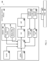
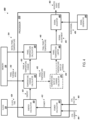
- the processor 310 includes a power calculator 410, an energy calculator 420, a temperature change calculator 430, a panel temperature calculator 440, a panel temperature limiter 450, and a signal adjuster 460.
- the processor 310 can also optionally include a temperature rate of change calculator 470.
- the power calculator 410 of the processor 310 can receive a time-varying coil current 404 and a time-varying coil voltage 402 from the current ADC 316 and the voltage ADC 318, respectively.
- the coil current 404 can be indicated, for example, in a unit of Amperes (A).
- the coil voltage can be indicated, for example, in a unit of Volts (V).
- the power calculator 410 can calculate a power 412 of the magnetic coil 210. Specifically, the power calculator 410 can multiply the coil current 404 and the coil voltage 402 at a particular time to calculate the power 412 at the particular time.
- the power calculator 410 may continuously calculate the time-varying power 412.
- the power 412 can be indicated, for example, in a unit of Watts (W).
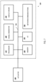
- An example graph of time-varying power 412 is shown in FIG. 5A .
- the power 412 can be represented on a graph as a function of time.
- the power 412 may increase, decrease, or remain steady over time while the actuator module 200 is in operation.
- the audio signal may increase and decrease in power over time due to changes in audio volume, e.g., music or voice volume.
- the power 412 is graphed over a period of time that includes a first time 510 and a second time 520.
- the first time 510 can be, for example, a period of time shortly after initially energizing the magnetic coil 210.
- the second time 520 can be a time later than the first time 510.
- the energy calculator 420 of the processor 310 can receive the time-varying power 412 from the power calculator 410.
- the energy calculator 420 can also receive a clock time 424 from the clock 320. Based on the varying power 412 over time, the energy calculator 420 can calculate an energy 422 supplied to the magnetic coil 210. Specifically, as shown in FIG. 5A , the energy calculator 420 can integrate the time-varying power 412 between the first time 510 and the second time 520 to determine the total energy 422 supplied between the first time 510 and the second time 520.
- the energy 422 is represented by an area under the curve representing the time-varying power 412.
- the energy 422 can be indicated, for example, in a unit of Joules (J).
- J Joules
- higher power levels maintained over longer periods of time result in a larger area under the curve, and thus larger amounts of energy supplied to the magnetic coil.
- the energy calculator 420 can output the energy 422 to the temperature change calculator 430.
- the temperature change calculator 430 can receive the energy 422 from the energy calculator 420, and the panel thermal model 352 from the memory 350.
- the panel thermal model 352 can be an experimental model. For example, experiments can be performed on the panel 104 or a similar panel to determine panel temperature behavior in response to energization of the magnetic coil 210. Experiments can include energizing the magnetic coil 210 at known power levels for various time durations, and measuring a resulting temperature of the panel 104. The resulting temperature of the panel 104 may be measured, for example, directly using a temperature sensor, or indirectly based on a resistance of the magnetic coil.
- the electronic control module can determine that the magnetic coil 210 and the panel are likely at approximately the same temperature.
- FIG. 5B shows an example temperature characteristic curve for the panel 104.
- the characteristic curve can be generated by energizing the magnetic coil 210 with an audio signal at a steady, known power for a time duration, and then turning the audio signal off.
- panel temperature 540 and actuator temperature 550 can be represented on a graph as a function of time.
- Temperature change 432 can be indicated, for example, in a unit of degrees Celsius (°C).
- the audio signal turns on and energizes the magnetic coil 210 at a constant power.
- the audio signal turns off.
- the actuator temperature 550 and the panel temperature 540 rise.
- the actuator temperature 550 rises due to being energized by the audio signal
- the panel temperature 540 rises due to heat transfer from the magnetic coil 210.
- the actuator temperature 550 may change temperature more rapidly than the panel temperature 540, due to the magnetic coil 210 having a lower thermal mass than the panel 104.
- the actuator temperature 550 and the panel temperature 540 fall.
- Temperature characteristic curves may be generated for various power levels and durations of time. From the temperature characteristic curves, the processor 310 can obtain a temperature rate of change for a particular power level at a given temperature. For example, the temperature characteristic curves can indicate that the panel temperature 540 changes 1 degree Celsius (°C) per minute per Watt at an initial temperature of 35°C. Temperature characteristic curves for the panel 104 may be generated experimentally and stored in the memory 350.
- the panel thermal model 352 can be a mathematical model.
- the panel thermal model 352 can include data representing heat transfer from the magnetic coil 210 to the panel 104, data representing heat transfer from the panel 104 to ambient, or both.
- the panel thermal model 352 can also include a model of panel temperature behavior in response to energization of the magnetic coil 210.
- the data may account for factors such as the specific heat capacity of the panel 104, the surface area of contact between the magnetic coil 210 and the panel 104, and the total surface area of the panel 104.
- the data may also account for factors such as changes in ambient temperature, changes in panel vibration frequency, and continuity of energization.
- the panel thermal model 352 can be a mathematical model that can be updated and verified experimentally.
- the panel thermal model 352 can be generated mathematically for predicted panel temperature. Experiments can then be performed on the panel 104 or a similar panel to verify and/or update the panel thermal model 352. Experiments can include energizing the magnetic coil 210 at steady power levels for various time durations and generating a temperature characteristic curves as shown in FIG. 5B . The resulting temperature of the panel 104 can be provided as feedback to the panel thermal model 352 in order to update the mathematical model.
- the panel thermal model 352 can be calibrated during a calibration phase of operation. For example, a preliminary thermal model may be programmed into the memory 350. During the calibration phase, the electronic control module 220 can energize the magnetic coil 210 at known power levels, and the panel temperature can be measured. The panel thermal model 352 can then be updated based on the panel temperature measured during the calibration phase.
- the panel thermal model 352 may continue to update during operation. For example, an audio signal may be applied to the magnetic coil 210 between a first time and a second time. While the audio signal is applied to the magnetic coil 210, the actuator temperature 550 and the panel temperature 540 rise.
- the audio signal may be off, or may be reduced to a lower power, such that heat from the actuator is no longer causing the panel temperature 540 to rise.
- the time duration may be equal to or longer than a threshold duration during which the actuator temperature 550 becomes approximately equal to the panel temperature 540.
- the processor 310 can then measure the resistance of the magnetic coil 210 to determine the actuator temperature 550, and therefore determine a measured panel temperature.
- the processor 310 can also determine a calculated panel temperature at the third time based on the panel thermal model 352. The processor 310 can then compare the measured panel temperature based on the actuator temperature 550 to the calculated panel temperature based on the thermal model. The processor 310 can calculate an error between the measured panel temperature and the calculated panel temperature. The processor 310 can provide the error as feedback to adjust one or more variables of the panel thermal model 532.
- an initial panel temperature 354 is 33°C.
- An audio signal is applied to the magnetic coil 210 between a first time T1 and a second time T2. At time T2, the audio signal turns off and remains off until time T3.
- the time duration between T2 and T3 is a time duration longer than the threshold duration during which the actuator temperature 550 becomes approximately equal to the panel temperature 540.
- the processor 310 measures the resistance of the magnetic coil 210 at time T3. Based on the resistance, the processor determines an actuator temperature of 40°C, and therefore a measured panel temperature of 40°C. The processor 310 determines a calculated panel temperature of 42°C based on the panel thermal model 352. The processor 310 calculates an error of 2°C. The processor 310 provides the error as feedback to adjust the panel thermal model 532.
- the audio signal may again be applied to the magnetic coil 210.
- the processor 310 can use the measured temperature at the third time as the initial panel temperature 354 for a next calculation of final panel temperature 442.
- the measured panel temperature of 40°C can be used as the initial panel temperature 354 for the next calculation of final panel temperature 442, e.g., the panel temperature at a fourth time T4.
- the panel thermal model 352 can include a panel thermal model curve 530 representing an association between energy and panel temperature change, as shown in FIG. 5C .
- the panel thermal model curve 530 may be generated based on temperature characteristic curves as shown in FIG. 5B .
- the temperature characteristic curve can provide temperature rate of change for a particular power level at a given temperature. From multiple temperature characteristic curves, the temperature rate of change for an amount of energy may be determined.
- multiple panel thermal model curve 530 may be generated for multiple initial temperatures.
- the panel thermal model curve 530 can be represented on a graph as a function of energy.
- the panel temperature change increases with increased energy, e.g., for a greater amount of energy supplied to the magnetic coil 210, the panel temperature may change a greater amount.
- FIG. 5C shows a curve with an approximately logarithmic shape, the shape of the panel thermal model curve 530 may vary depending on characteristics of the panel.
- the shape of the panel thermal model curve 530 may be, for example, linear, exponential, or parabolic.
- the panel thermal model 352 can be programmed into the memory 350.
- the processor 310 can then access the panel thermal model 352 from the memory 350 in order to determine the panel temperature change 430.
- the temperature change calculator 430 can calculate a panel temperature change associated with the energy 422.
- the temperature change calculator 430 calculates a panel temperature change 432.
- the panel temperature change 432 represents the change in panel temperature between the first time 510 and the second time 520.
- the temperature change calculator 430 can output the panel temperature change 432 to the panel temperature calculator 440.
- the panel temperature calculator 440 can receive the panel temperature change 432 from the temperature change calculator 430, and the initial, or first, panel temperature 354 from the memory 350.
- the initial panel temperature 354 can be the panel temperature at the first time 510.
- the processor 310 can determine the initial panel temperature 354, and store the initial panel temperature 354 in the memory 350.
- the panel temperature limiter 450 can be programmed to output the signal adjustment 452 for a designated period of time. For example, in response to determining that the final panel temperature 442 exceeds the threshold panel temperature, the panel temperature limiter 450 may determine to output a signal adjustment 452 of reducing the audio signal power by one half for a period of time of one minute. In some examples, following the period of time of one minute, the panel temperature limiter 450 can automatically remove the signal adjustment 452.
- the processor 310 may transmit a command to the amplifier 360 to adjust amplification.
- the processor 310 may transmit a command to the amplifier 360 to reduce amplification of the analog electrical signal, e.g., by one-half.
- the amplifier 360 can then reduce the amplification of the analog electrical signal for a designated period of time, or until receiving a subsequent command from the processor 310 to cease reducing the amplification.
- the current through the magnetic coil 210 is reduced. Due to the current being reduced, the magnetic coil 210 may then increase temperature at a slower rate, cease increasing in temperature, or decrease in temperature. Due to thermal communication between the magnetic coil 210 and the panel 104, the panel 104 may likewise increase temperature at a slower rate, cease increasing in temperature, or decrease in temperature.
- the processor 310 can continue to monitor coil current 404 and coil voltage 402 in order to re-calculate changes in panel temperature.
Landscapes
- Physics & Mathematics (AREA)
- Engineering & Computer Science (AREA)
- Acoustics & Sound (AREA)
- Signal Processing (AREA)
- Health & Medical Sciences (AREA)
- General Health & Medical Sciences (AREA)
- Otolaryngology (AREA)
- Apparatuses For Generation Of Mechanical Vibrations (AREA)
- Electric Clocks (AREA)
- Audible-Bandwidth Dynamoelectric Transducers Other Than Pickups (AREA)
Claims (15)
- Plattenaudiolautsprecher, umfassend:eine Platte (104);einen Aktuator (200), der an einer Fläche der Platte befestigt und dazu konfiguriert ist, eine Schwingung der Platte zu veranlassen, wobei der Aktuator eine Magnetspule (210) in termischer Kommunikation mit der Platte umfasst;eine Vielzahl von elektrischen Sensoren (312, 314), die elektrisch mit der Magnetspule gekoppelt und dazu konfiguriert ist, zeitabhängige elektrische Daten für die Magnetspule auszugeben; undein elektronisches Steuermodul (220) in Kommunikation mit der Magnetspule und der Vielzahl von elektrischen Sensoren, wobei das elektronische Steuermodul dazu konfiguriert ist, Vorgänge durchzuführen, die Folgendes umfassen:Bereitstellen eines Stroms an die Magnetspule;Empfangen der zeitabhängigen elektrischen Daten (402, 404) für die Magnetspule von der Vielzahl von elektrischen Sensoren;basierend auf den zeitabhängigen elektrischen Daten für die Magnetspule, Bestimmen einer elektrischen Energie (422), die der Magnetspule zwischen einem ersten Zeitpunkt und einem zweiten Zeitpunkt bereitgestellt wird;Zugreifen auf ein thermisches Modell (352, 530) der Platte; und basierend auf der elektrischen Energie, die der Magnetspule bereitgestellt wird, und dem thermischen Modell der Platte, Bestimmen einer Änderung (432) einer Plattentemperatur zwischen dem ersten Zeitpunkt und dem zweiten Zeitpunkt.
- Plattenaudiolautsprecher nach Anspruch 1, wobei die zeitabhängigen elektrischen Daten eines oder mehrere von Folgendem umfassen:einen zeitabhängigen Strom (404) durch die Magnetspule; undeine zeitabhängige Spannung (402) über die Magnetspule.
- Plattenlautsprecher nach einem der Ansprüche 1-2, wobei das thermische Modell der Platte eines oder mehrere von Folgendem umfasst:Daten, die die Wärmeübertragung von der Magnetspule zu der Platte darstellen; undDaten, die die Wärmeübertragung von der Platte an die Umgebung darstellen.
- Plattenaudiolautsprecher nach einem der Ansprüche 1-3, wobei das thermische Modell der Platte eine Zuordnungskurve (530) zwischen der der Magnetspule bereitgestellten elektrischen Energie und der Änderung der Plattentemperatur umfasst.
- Plattenaudiolautsprecher nach einem der Ansprüche 1-4, wobei das Bestimmen der elektrischen Energie, die der Magnetspule bereitgestellt wird, Folgendes umfasst:Bestimmen einer zeitabhängigen Leistung (412), die der Magnetspule bereitgestellt wird, aus den zeitabhängigen elektrischen Daten für die Magnetspule; undIntegrieren der zeitabhängigen Leistung zwischen dem ersten und dem zweiten Zeitpunkt.
- Plattenaudiolautsprecher nach einem der Ansprüche 1-5, wobei die Vorgänge ferner Folgendes umfassen:Bestimmen einer ersten Plattentemperatur zum ersten Zeitpunkt aus den zeitabhängigen elektrischen Daten für die Magnetspule und dem thermischen Modell der Platte;basierend auf der ersten Plattentemperatur und der Änderung der Plattentemperatur zwischen dem ersten Zeitpunkt und dem zweiten Zeitpunkt, Bestimmen einer zweiten Plattentemperatur zum zweiten Zeitpunkt; undbasierend auf der zweiten Plattentemperatur, Anpassen des an die Magnetspule bereitgestellten Stroms.
- Plattenaudiolautsprecher nach einem der Ansprüche 1-6, wobei die Vorgänge ferner Folgendes umfassen:Bestimmen einer Änderungsrate (434) der Plattentemperatur aus der Änderung der Plattentemperatur zwischen dem ersten Zeitpunkt und dem zweiten Zeitpunkt; undbasierend auf der Änderungsrate der Plattentemperatur, Anpassen des an die Magnetspule bereitgestellten Stroms.
- Plattenaudiolautsprecher nach einem der Ansprüche 1-7, wobei das elektronische Steuermodul eines oder mehrere von einer Audiosignalquelle (340), einem Verstärker (360) und einem digitalen Signalprozessor (310) umfasst.
- Plattenaudiolautsprecher nach einem der Ansprüche 1 bis 8, wobei die Platte eine Anzeigeplatte umfasst.
- Mobile Vorrichtung (100), umfassend:ein Gehäuse (102); undden Plattenaudiolautsprecher nach einem der Ansprüche 1-9.
- Mobile Vorrichtung nach Anspruch 10, wobei die mobile Vorrichtung ein Mobiltelefon oder ein Tablet-Computer umfasst.
- Tragbare Vorrichtung, umfassend:ein Gehäuse; undden Plattenaudiolautsprecher nach einem der Ansprüche 1-9.
- Tragbare Vorrichtung nach Anspruch 12, wobei die tragbare Vorrichtung eine Smart-Uhr oder eine kopfmontierte Anzeige ist.
- Verfahren für einen Plattenaudiolautsprecher, wobei das Verfahren Folgendes umfasst:Bereitstellen eines Stroms an eine Magnetspule eines Aktuators,um eine Vibration einer Platte zu veranlassen, wobei die Magnetspule in thermischem Austausch mit der Platte steht;Empfangen von zeitabhängigen elektrischen Daten für die Magnetspule von einer Vielzahl von elektrischen Sensoren, die elektrisch mit der Magnetspule gekoppelt ist;basierend auf den zeitabhängigen elektrischen Daten für die Magnetspule, Bestimmen einer elektrischen Energie, die der Magnetspule zwischen einem ersten Zeitpunkt und einem zweiten Zeitpunkt bereitgestellt wird;Zugreifen auf ein thermisches Modell der Platte; undbasierend auf der elektrischen Energie, die der Magnetspule bereitgestellt wird, und dem thermischen Modell der Platte, Bestimmen einer Änderung einer Plattentemperatur zwischen dem ersten Zeitpunkt und dem zweiten Zeitpunkt.
- Verfahren nach Anspruch 14, ferner umfassend:Bestimmen einer ersten Plattentemperatur zum ersten Zeitpunkt aus den zeitabhängigen elektrischen Daten für die Magnetspule und dem thermischen Modell der Platte; Bestimmen einer zweiten Plattentemperatur zum zweiten Zeitpunkt basierend auf der ersten Plattentemperatur und der Änderung der Plattentemperatur zwischen dem ersten Zeitpunkt und dem zweiten Zeitpunkt; undAnpassen des der Magnetspule bereitgestellten Stroms basierend auf der zweiten Plattentemperatur, wobei das Anpassen des der Magnetspule bereitgestellten Stroms optional das Verringern des der Magnetspule bereitgestellten Stroms umfasst;
und/oderBestimmen einer Änderungsrate der Plattentemperatur aus der Änderung der Plattentemperatur zwischen dem ersten Zeitpunkt und dem zweiten Zeitpunkt; und Anpassen des bereitgestellten Stroms für die Magnetspule basierend auf der Änderungsrate der Plattentemperatur, wobei das Anpassen des bereitgestellten Stroms für die Magnetspule optional das Verringern des bereitgestellten Stroms für die Magnetspule umfasst.
Applications Claiming Priority (1)
| Application Number | Priority Date | Filing Date | Title |
|---|---|---|---|
| PCT/US2020/022693 WO2021183139A1 (en) | 2020-03-13 | 2020-03-13 | Panel loudspeaker temperature monitoring and control |
Publications (2)
| Publication Number | Publication Date |
|---|---|
| EP4101180A1 EP4101180A1 (de) | 2022-12-14 |
| EP4101180B1 true EP4101180B1 (de) | 2025-07-02 |
Family
ID=70228835
Family Applications (1)
| Application Number | Title | Priority Date | Filing Date |
|---|---|---|---|
| EP20718055.5A Active EP4101180B1 (de) | 2020-03-13 | 2020-03-13 | Plattenlautsprechertemperaturüberwachung und -steuerung |
Country Status (5)
| Country | Link |
|---|---|
| US (2) | US12035090B2 (de) |
| EP (1) | EP4101180B1 (de) |
| KR (1) | KR102676626B1 (de) |
| CN (1) | CN115244946B (de) |
| WO (1) | WO2021183139A1 (de) |
Families Citing this family (2)
| Publication number | Priority date | Publication date | Assignee | Title |
|---|---|---|---|---|
| WO2021216076A1 (en) * | 2020-04-24 | 2021-10-28 | Google Llc | Voice coils for use with temperature sensors and devices including the same |
| US11638093B2 (en) * | 2020-06-30 | 2023-04-25 | Waves Audio Ltd. | Thermal limiter for a panel speaker |
Family Cites Families (32)
| Publication number | Priority date | Publication date | Assignee | Title |
|---|---|---|---|---|
| DE602005019435D1 (de) * | 2005-12-14 | 2010-04-01 | Harman Becker Automotive Sys | Verfahren und Vorrichtung zum Vorhersehen des Verhaltens eines Wandlers |
| JP2008219647A (ja) * | 2007-03-06 | 2008-09-18 | Funai Electric Co Ltd | テレビジョン、及び音声出力機器 |
| KR20100057261A (ko) | 2008-11-21 | 2010-05-31 | 삼성전기주식회사 | 보이스 코일 온도 측정 장치 및 방법 |
| DE112009005469B4 (de) * | 2009-12-24 | 2019-06-27 | Nokia Technologies Oy | Lautsprecherschutzvorrichtung und Verfahren dafür |
| JP5131939B2 (ja) * | 2010-08-26 | 2013-01-30 | 株式会社村田製作所 | 圧電デバイス |
| EP2538555B1 (de) * | 2011-06-22 | 2019-09-11 | Nxp B.V. | Steuerung einer Lautsprecherausgabe |
| US9131302B2 (en) * | 2012-06-11 | 2015-09-08 | Apple Inc. | Speaker temperature control using speaker temperature and speaker impedance estimates |
| EP2712209B1 (de) * | 2012-09-21 | 2021-01-13 | Dialog Semiconductor BV | Verfahren und Vorrichtung zur Berechung metrischer Werte für Lautsprecherschutz |
| DE102012020271A1 (de) * | 2012-10-17 | 2014-04-17 | Wolfgang Klippel | Anordnung und Verfahren zur Steuerung von Wandlern |
| CN103813236A (zh) * | 2012-11-07 | 2014-05-21 | 飞兆半导体公司 | 扬声器保护的相关方法及装置 |
| US9226071B2 (en) * | 2012-12-13 | 2015-12-29 | Maxim Integrated Products, Inc. | Direct measurement of an input signal to a loudspeaker to determine and limit a temperature of a voice coil of the loudspeaker |
| CN105409240A (zh) * | 2013-07-25 | 2016-03-16 | 株式会社特瑞君思半导体 | 扬声器控制装置 |
| WO2015143127A1 (en) * | 2014-03-19 | 2015-09-24 | Actiwave Ab | Non-linear control of loudspeakers |
| US9414160B2 (en) * | 2014-11-27 | 2016-08-09 | Blackberry Limited | Method, system and apparatus for loudspeaker excursion domain processing |
| US9473851B2 (en) * | 2014-12-22 | 2016-10-18 | Qualcomm Incorporated | Speaker protection circuit with improved accuracy |
| US10338883B2 (en) * | 2015-05-22 | 2019-07-02 | Cirrus Logic, Inc. | Adaptive receiver |
| US9942676B1 (en) | 2015-08-05 | 2018-04-10 | Apple Inc. | Method and system of throttling a pilot tone for thermal monitoring of an electro-mechanical actuator |
| US9807528B1 (en) * | 2015-09-21 | 2017-10-31 | Apple Inc. | Electronic devices and method for thermal monitoring of an electro-mechanical actuator |
| US9794687B2 (en) * | 2015-09-28 | 2017-10-17 | Cirrus Logic, Inc. | Loudspeaker protection circuitry and methods |
| CN206164766U (zh) * | 2016-11-20 | 2017-05-10 | 恩平市仙笛音响器材有限公司 | 一种具有自保护功能的功放机 |
| KR102370839B1 (ko) * | 2017-05-11 | 2022-03-04 | 엘지디스플레이 주식회사 | 표시장치 |
| US10381994B2 (en) | 2017-12-21 | 2019-08-13 | Harman International Industries, Incorporated | Constrained nonlinear parameter estimation for robust nonlinear loudspeaker modeling for the purpose of smart limiting |
| US10848874B2 (en) * | 2018-02-20 | 2020-11-24 | Google Llc | Panel audio loudspeaker electromagnetic actuator |
| US10250978B1 (en) * | 2018-02-26 | 2019-04-02 | Texas Instruments Incorporated | Voice coil temperature control based on an estimated voice coil temperature and a threshold |
| EP3758392B1 (de) * | 2018-04-03 | 2022-05-11 | Honor Device Co., Ltd. | Lautsprecher, endgerät und lautsprechersteuerungsverfahren |
| FR3087074B1 (fr) * | 2018-10-08 | 2022-02-25 | Devialet | Dispositif de commande d'un haut-parleur et installation de restitution sonore associee |
| US10897670B1 (en) * | 2018-10-31 | 2021-01-19 | Amazon Technologies, Inc. | Excursion and thermal management for audio output devices |
| TWI749469B (zh) * | 2019-02-28 | 2021-12-11 | 南韓商樂金顯示科技股份有限公司 | 顯示設備 |
| JP7611234B2 (ja) * | 2019-09-03 | 2025-01-09 | エリプティック ラボラトリーズ エーエスエー | 電子機器の近傍に物体があることを検出するための方法、コンピュータ可読プログラムコード、コンピュータ可読記憶媒体、およびコンピュータソフトウエア製品 |
| KR102808319B1 (ko) * | 2019-11-27 | 2025-05-14 | 엘지디스플레이 주식회사 | 표시장치 |
| US11159888B1 (en) * | 2020-09-18 | 2021-10-26 | Cirrus Logic, Inc. | Transducer cooling by introduction of a cooling component in the transducer input signal |
| US11153682B1 (en) * | 2020-09-18 | 2021-10-19 | Cirrus Logic, Inc. | Micro-speaker audio power reproduction system and method with reduced energy use and thermal protection using micro-speaker electro-acoustic response and human hearing thresholds |
-
2020
- 2020-03-13 EP EP20718055.5A patent/EP4101180B1/de active Active
- 2020-03-13 WO PCT/US2020/022693 patent/WO2021183139A1/en not_active Ceased
- 2020-03-13 US US17/910,100 patent/US12035090B2/en active Active
- 2020-03-13 KR KR1020227031107A patent/KR102676626B1/ko active Active
- 2020-03-13 CN CN202080098387.2A patent/CN115244946B/zh active Active
-
2024
- 2024-06-11 US US18/740,244 patent/US12335674B2/en active Active
Also Published As
| Publication number | Publication date |
|---|---|
| KR20220139954A (ko) | 2022-10-17 |
| US20230113894A1 (en) | 2023-04-13 |
| US12335674B2 (en) | 2025-06-17 |
| US20240334106A1 (en) | 2024-10-03 |
| EP4101180A1 (de) | 2022-12-14 |
| KR102676626B1 (ko) | 2024-06-20 |
| WO2021183139A1 (en) | 2021-09-16 |
| CN115244946A (zh) | 2022-10-25 |
| CN115244946B (zh) | 2025-05-30 |
| US12035090B2 (en) | 2024-07-09 |
Similar Documents
| Publication | Publication Date | Title |
|---|---|---|
| US12335674B2 (en) | Panel audio temperature monitoring | |
| EP3179335B1 (de) | Steuerung von haptischem feedback | |
| EP2797340B1 (de) | Tonleistungsverwaltungssystem | |
| WO2017055808A1 (en) | Loudspeaker protection circuitry and methods | |
| US11638093B2 (en) | Thermal limiter for a panel speaker | |
| TW201526669A (zh) | 揚聲器的驅動訊號的產生裝置及方法 | |
| US12063488B2 (en) | Audio panel temperature control | |
| KR102874421B1 (ko) | 온도 센서와 함께 사용하기 위한 보이스 코일 및 이를 포함하는 장치 |
Legal Events
| Date | Code | Title | Description |
|---|---|---|---|
| STAA | Information on the status of an ep patent application or granted ep patent |
Free format text: STATUS: UNKNOWN |
|
| STAA | Information on the status of an ep patent application or granted ep patent |
Free format text: STATUS: THE INTERNATIONAL PUBLICATION HAS BEEN MADE |
|
| PUAI | Public reference made under article 153(3) epc to a published international application that has entered the european phase |
Free format text: ORIGINAL CODE: 0009012 |
|
| STAA | Information on the status of an ep patent application or granted ep patent |
Free format text: STATUS: REQUEST FOR EXAMINATION WAS MADE |
|
| 17P | Request for examination filed |
Effective date: 20220909 |
|
| AK | Designated contracting states |
Kind code of ref document: A1 Designated state(s): AL AT BE BG CH CY CZ DE DK EE ES FI FR GB GR HR HU IE IS IT LI LT LU LV MC MK MT NL NO PL PT RO RS SE SI SK SM TR |
|
| DAV | Request for validation of the european patent (deleted) | ||
| DAX | Request for extension of the european patent (deleted) | ||
| GRAP | Despatch of communication of intention to grant a patent |
Free format text: ORIGINAL CODE: EPIDOSNIGR1 |
|
| STAA | Information on the status of an ep patent application or granted ep patent |
Free format text: STATUS: GRANT OF PATENT IS INTENDED |
|
| INTG | Intention to grant announced |
Effective date: 20250403 |
|
| GRAS | Grant fee paid |
Free format text: ORIGINAL CODE: EPIDOSNIGR3 |
|
| GRAA | (expected) grant |
Free format text: ORIGINAL CODE: 0009210 |
|
| STAA | Information on the status of an ep patent application or granted ep patent |
Free format text: STATUS: THE PATENT HAS BEEN GRANTED |
|
| P01 | Opt-out of the competence of the unified patent court (upc) registered |
Free format text: CASE NUMBER: APP_22285/2025 Effective date: 20250512 |
|
| AK | Designated contracting states |
Kind code of ref document: B1 Designated state(s): AL AT BE BG CH CY CZ DE DK EE ES FI FR GB GR HR HU IE IS IT LI LT LU LV MC MK MT NL NO PL PT RO RS SE SI SK SM TR |
|
| REG | Reference to a national code |
Ref country code: GB Ref legal event code: FG4D |
|
| REG | Reference to a national code |
Ref country code: CH Ref legal event code: EP |
|
| REG | Reference to a national code |
Ref country code: DE Ref legal event code: R096 Ref document number: 602020053758 Country of ref document: DE |
|
| REG | Reference to a national code |
Ref country code: IE Ref legal event code: FG4D |
|
| REG | Reference to a national code |
Ref country code: NL Ref legal event code: MP Effective date: 20250702 |
|
| PG25 | Lapsed in a contracting state [announced via postgrant information from national office to epo] |
Ref country code: PT Free format text: LAPSE BECAUSE OF FAILURE TO SUBMIT A TRANSLATION OF THE DESCRIPTION OR TO PAY THE FEE WITHIN THE PRESCRIBED TIME-LIMIT Effective date: 20251103 |
|
| PG25 | Lapsed in a contracting state [announced via postgrant information from national office to epo] |
Ref country code: NL Free format text: LAPSE BECAUSE OF FAILURE TO SUBMIT A TRANSLATION OF THE DESCRIPTION OR TO PAY THE FEE WITHIN THE PRESCRIBED TIME-LIMIT Effective date: 20250702 |
|
| REG | Reference to a national code |
Ref country code: AT Ref legal event code: MK05 Ref document number: 1810665 Country of ref document: AT Kind code of ref document: T Effective date: 20250702 |
|
| PG25 | Lapsed in a contracting state [announced via postgrant information from national office to epo] |
Ref country code: IS Free format text: LAPSE BECAUSE OF FAILURE TO SUBMIT A TRANSLATION OF THE DESCRIPTION OR TO PAY THE FEE WITHIN THE PRESCRIBED TIME-LIMIT Effective date: 20251102 |
|
| PG25 | Lapsed in a contracting state [announced via postgrant information from national office to epo] |
Ref country code: NO Free format text: LAPSE BECAUSE OF FAILURE TO SUBMIT A TRANSLATION OF THE DESCRIPTION OR TO PAY THE FEE WITHIN THE PRESCRIBED TIME-LIMIT Effective date: 20251002 |
|
| REG | Reference to a national code |
Ref country code: LT Ref legal event code: MG9D |
|
| PG25 | Lapsed in a contracting state [announced via postgrant information from national office to epo] |
Ref country code: AT Free format text: LAPSE BECAUSE OF FAILURE TO SUBMIT A TRANSLATION OF THE DESCRIPTION OR TO PAY THE FEE WITHIN THE PRESCRIBED TIME-LIMIT Effective date: 20250702 |
|
| PG25 | Lapsed in a contracting state [announced via postgrant information from national office to epo] |
Ref country code: FI Free format text: LAPSE BECAUSE OF FAILURE TO SUBMIT A TRANSLATION OF THE DESCRIPTION OR TO PAY THE FEE WITHIN THE PRESCRIBED TIME-LIMIT Effective date: 20250702 |
|
| PG25 | Lapsed in a contracting state [announced via postgrant information from national office to epo] |
Ref country code: HR Free format text: LAPSE BECAUSE OF FAILURE TO SUBMIT A TRANSLATION OF THE DESCRIPTION OR TO PAY THE FEE WITHIN THE PRESCRIBED TIME-LIMIT Effective date: 20250702 |
|
| PG25 | Lapsed in a contracting state [announced via postgrant information from national office to epo] |
Ref country code: GR Free format text: LAPSE BECAUSE OF FAILURE TO SUBMIT A TRANSLATION OF THE DESCRIPTION OR TO PAY THE FEE WITHIN THE PRESCRIBED TIME-LIMIT Effective date: 20251003 |
|
| PG25 | Lapsed in a contracting state [announced via postgrant information from national office to epo] |
Ref country code: SE Free format text: LAPSE BECAUSE OF FAILURE TO SUBMIT A TRANSLATION OF THE DESCRIPTION OR TO PAY THE FEE WITHIN THE PRESCRIBED TIME-LIMIT Effective date: 20250702 Ref country code: CZ Free format text: LAPSE BECAUSE OF FAILURE TO SUBMIT A TRANSLATION OF THE DESCRIPTION OR TO PAY THE FEE WITHIN THE PRESCRIBED TIME-LIMIT Effective date: 20250702 |
|
| PG25 | Lapsed in a contracting state [announced via postgrant information from national office to epo] |
Ref country code: LV Free format text: LAPSE BECAUSE OF FAILURE TO SUBMIT A TRANSLATION OF THE DESCRIPTION OR TO PAY THE FEE WITHIN THE PRESCRIBED TIME-LIMIT Effective date: 20250702 |
|
| PG25 | Lapsed in a contracting state [announced via postgrant information from national office to epo] |
Ref country code: BG Free format text: LAPSE BECAUSE OF FAILURE TO SUBMIT A TRANSLATION OF THE DESCRIPTION OR TO PAY THE FEE WITHIN THE PRESCRIBED TIME-LIMIT Effective date: 20250702 Ref country code: PL Free format text: LAPSE BECAUSE OF FAILURE TO SUBMIT A TRANSLATION OF THE DESCRIPTION OR TO PAY THE FEE WITHIN THE PRESCRIBED TIME-LIMIT Effective date: 20250702 |
|
| PG25 | Lapsed in a contracting state [announced via postgrant information from national office to epo] |
Ref country code: RS Free format text: LAPSE BECAUSE OF FAILURE TO SUBMIT A TRANSLATION OF THE DESCRIPTION OR TO PAY THE FEE WITHIN THE PRESCRIBED TIME-LIMIT Effective date: 20251002 |
|
| PG25 | Lapsed in a contracting state [announced via postgrant information from national office to epo] |
Ref country code: ES Free format text: LAPSE BECAUSE OF FAILURE TO SUBMIT A TRANSLATION OF THE DESCRIPTION OR TO PAY THE FEE WITHIN THE PRESCRIBED TIME-LIMIT Effective date: 20250702 |
|
| PG25 | Lapsed in a contracting state [announced via postgrant information from national office to epo] |
Ref country code: SM Free format text: LAPSE BECAUSE OF FAILURE TO SUBMIT A TRANSLATION OF THE DESCRIPTION OR TO PAY THE FEE WITHIN THE PRESCRIBED TIME-LIMIT Effective date: 20250702 |
|
| PGFP | Annual fee paid to national office [announced via postgrant information from national office to epo] |
Ref country code: GB Payment date: 20260327 Year of fee payment: 7 |
|
| PG25 | Lapsed in a contracting state [announced via postgrant information from national office to epo] |
Ref country code: DK Free format text: LAPSE BECAUSE OF FAILURE TO SUBMIT A TRANSLATION OF THE DESCRIPTION OR TO PAY THE FEE WITHIN THE PRESCRIBED TIME-LIMIT Effective date: 20250702 |
|
| PGFP | Annual fee paid to national office [announced via postgrant information from national office to epo] |
Ref country code: DE Payment date: 20260327 Year of fee payment: 7 |
|
| PG25 | Lapsed in a contracting state [announced via postgrant information from national office to epo] |
Ref country code: IT Free format text: LAPSE BECAUSE OF FAILURE TO SUBMIT A TRANSLATION OF THE DESCRIPTION OR TO PAY THE FEE WITHIN THE PRESCRIBED TIME-LIMIT Effective date: 20250702 |
|
| PG25 | Lapsed in a contracting state [announced via postgrant information from national office to epo] |
Ref country code: EE Free format text: LAPSE BECAUSE OF FAILURE TO SUBMIT A TRANSLATION OF THE DESCRIPTION OR TO PAY THE FEE WITHIN THE PRESCRIBED TIME-LIMIT Effective date: 20250702 Ref country code: SK Free format text: LAPSE BECAUSE OF FAILURE TO SUBMIT A TRANSLATION OF THE DESCRIPTION OR TO PAY THE FEE WITHIN THE PRESCRIBED TIME-LIMIT Effective date: 20250702 |