EP4100780B1 - Verfahren zur anzeige eines scharfen bildes auf einer netzhaut eines auges einer person - Google Patents
Verfahren zur anzeige eines scharfen bildes auf einer netzhaut eines auges einer person Download PDFInfo
- Publication number
- EP4100780B1 EP4100780B1 EP21702691.3A EP21702691A EP4100780B1 EP 4100780 B1 EP4100780 B1 EP 4100780B1 EP 21702691 A EP21702691 A EP 21702691A EP 4100780 B1 EP4100780 B1 EP 4100780B1
- Authority
- EP
- European Patent Office
- Prior art keywords
- image
- eye
- person
- sub
- retina
- Prior art date
- Legal status (The legal status is an assumption and is not a legal conclusion. Google has not performed a legal analysis and makes no representation as to the accuracy of the status listed.)
- Active
Links
Images


Classifications
-
- G—PHYSICS
- G02—OPTICS
- G02B—OPTICAL ELEMENTS, SYSTEMS OR APPARATUS
- G02B27/00—Optical systems or apparatus not provided for by any of the groups G02B1/00 - G02B26/00, G02B30/00
- G02B27/01—Head-up displays
- G02B27/017—Head mounted
-
- G—PHYSICS
- G09—EDUCATION; CRYPTOGRAPHY; DISPLAY; ADVERTISING; SEALS
- G09G—ARRANGEMENTS OR CIRCUITS FOR CONTROL OF INDICATING DEVICES USING STATIC MEANS TO PRESENT VARIABLE INFORMATION
- G09G3/00—Control arrangements or circuits, of interest only in connection with visual indicators other than cathode-ray tubes
- G09G3/001—Control arrangements or circuits, of interest only in connection with visual indicators other than cathode-ray tubes using specific devices not provided for in groups G09G3/02 - G09G3/36, e.g. using an intermediate record carrier such as a film slide; Projection systems; Display of non-alphanumerical information, solely or in combination with alphanumerical information, e.g. digital display on projected diapositive as background
- G09G3/002—Control arrangements or circuits, of interest only in connection with visual indicators other than cathode-ray tubes using specific devices not provided for in groups G09G3/02 - G09G3/36, e.g. using an intermediate record carrier such as a film slide; Projection systems; Display of non-alphanumerical information, solely or in combination with alphanumerical information, e.g. digital display on projected diapositive as background to project the image of a two-dimensional display, such as an array of light emitting or modulating elements or a CRT
-
- A—HUMAN NECESSITIES
- A61—MEDICAL OR VETERINARY SCIENCE; HYGIENE
- A61B—DIAGNOSIS; SURGERY; IDENTIFICATION
- A61B3/00—Apparatus for testing the eyes; Instruments for examining the eyes
- A61B3/0016—Operational features thereof
- A61B3/0033—Operational features thereof characterised by user input arrangements
-
- A—HUMAN NECESSITIES
- A61—MEDICAL OR VETERINARY SCIENCE; HYGIENE
- A61B—DIAGNOSIS; SURGERY; IDENTIFICATION
- A61B3/00—Apparatus for testing the eyes; Instruments for examining the eyes
- A61B3/0016—Operational features thereof
- A61B3/0041—Operational features thereof characterised by display arrangements
- A61B3/005—Constructional features of the display
-
- A—HUMAN NECESSITIES
- A61—MEDICAL OR VETERINARY SCIENCE; HYGIENE
- A61B—DIAGNOSIS; SURGERY; IDENTIFICATION
- A61B3/00—Apparatus for testing the eyes; Instruments for examining the eyes
- A61B3/02—Subjective types, i.e. testing apparatus requiring the active assistance of the patient
- A61B3/028—Subjective types, i.e. testing apparatus requiring the active assistance of the patient for testing visual acuity; for determination of refraction, e.g. phoropters
- A61B3/032—Devices for presenting test symbols or characters, e.g. test chart projectors
-
- A—HUMAN NECESSITIES
- A61—MEDICAL OR VETERINARY SCIENCE; HYGIENE
- A61B—DIAGNOSIS; SURGERY; IDENTIFICATION
- A61B3/00—Apparatus for testing the eyes; Instruments for examining the eyes
- A61B3/02—Subjective types, i.e. testing apparatus requiring the active assistance of the patient
- A61B3/028—Subjective types, i.e. testing apparatus requiring the active assistance of the patient for testing visual acuity; for determination of refraction, e.g. phoropters
- A61B3/036—Subjective types, i.e. testing apparatus requiring the active assistance of the patient for testing visual acuity; for determination of refraction, e.g. phoropters for testing astigmatism
-
- G—PHYSICS
- G02—OPTICS
- G02B—OPTICAL ELEMENTS, SYSTEMS OR APPARATUS
- G02B27/00—Optical systems or apparatus not provided for by any of the groups G02B1/00 - G02B26/00, G02B30/00
- G02B27/0093—Optical systems or apparatus not provided for by any of the groups G02B1/00 - G02B26/00, G02B30/00 with means for monitoring data relating to the user, e.g. head-tracking, eye-tracking
-
- G—PHYSICS
- G09—EDUCATION; CRYPTOGRAPHY; DISPLAY; ADVERTISING; SEALS
- G09G—ARRANGEMENTS OR CIRCUITS FOR CONTROL OF INDICATING DEVICES USING STATIC MEANS TO PRESENT VARIABLE INFORMATION
- G09G2340/00—Aspects of display data processing
- G09G2340/04—Changes in size, position or resolution of an image
- G09G2340/0464—Positioning
- G09G2340/0471—Vertical positioning
-
- G—PHYSICS
- G09—EDUCATION; CRYPTOGRAPHY; DISPLAY; ADVERTISING; SEALS
- G09G—ARRANGEMENTS OR CIRCUITS FOR CONTROL OF INDICATING DEVICES USING STATIC MEANS TO PRESENT VARIABLE INFORMATION
- G09G2340/00—Aspects of display data processing
- G09G2340/04—Changes in size, position or resolution of an image
- G09G2340/0464—Positioning
- G09G2340/0478—Horizontal positioning
-
- G—PHYSICS
- G09—EDUCATION; CRYPTOGRAPHY; DISPLAY; ADVERTISING; SEALS
- G09G—ARRANGEMENTS OR CIRCUITS FOR CONTROL OF INDICATING DEVICES USING STATIC MEANS TO PRESENT VARIABLE INFORMATION
- G09G2354/00—Aspects of interface with display user
Definitions
- the invention relates to a method for displaying a sharp image on the retina of an eye of a person.
- the invention further relates to a method for determining at least one parameter of an eye of a person.
- a head-mounted system is an electro-optical device worn on the head by a wearer. Usually such system is electronically controlled so as to switch between different stages or to display information to the wearer.
- a head mounted system usually presents like a spectacle frame with electronically controlled spectacle lenses.
- Head-mounted system are used according to various usage pattern such as non-immersive head-mounted system that allows the wearer to interact with their environment while using the head-mounted system or immersive head-mounted system that cuts off the field of outside view.
- a head mounted optical device for example a head mounted display system, adapted to a wearer, in particular adapted to its visual needs in a simply manner and preferably in a late step of the manufacturing of the optical device in order to limit the unit production cost.
- the head mounted optical system should be adapted to such requirements.
- an optical device for example a head-mounted see-through system, adapted to a wearer and in particular to a wearer's prescription.
- US 10 451 895 B2 discloses methods and a wearable ophthalmic device that may include an outward facing head-mounted light field camera to receive light from a user's surroundings and to generate numerical light field image data.
- EP 3 296 797 A1 relates to methods and apparatus to display an image on a person's vision using a display built into eyewear.
- the invention proposes a method for displaying a sharp image on a retina of an eye of the person, the person having a prescription for the eye of the person, the method comprising:
- such method allows customizing a head-mounted display device to the user's viewing ability.
- such method allows a pre-compensation of the image to be displayed on the retina of the user based on the prescription of the eye of the user, so as to display a sharp image on the retina of the user.
- the use of the head-mounted display device and the virtual comfort of the virtual image is optimized for the user.
- a single head-mounted device could be used by different persons having different prescription, the image to be displayed on the retina of each person being corrected based on a prescription of the eye of the person determined by the same head-mounted device.
- the invention further relates to a display device adapted to provide a plurality of light beams configured to be focused substantially in the plane of a pupil of the eye at a plurality of corresponding different positions, each light beam being configured to carry an associated sub-image and adapted to execute at least the steps of the method of the invention.
- the invention further relates to a device comprising a processor adapted to store one or more sequence of instructions and to carry out at least one of the steps of the method for displaying a sharp image on a retina of an eye of the person according to the invention.
- the invention relates to a computer program product comprising one or more stored sequences of instructions that are accessible to a processor and which, when executed by the processor, causes the processor to carry out at least the following steps of the method for determining at least one optical parameter of an eye of a person according to the invention, using a display device according to the invention:
- the invention further relates to a computer readable medium carrying one or more sequences of instructions of the computer program product according to the invention.
- Embodiments of the present invention may include apparatuses for performing the operations herein.
- This apparatus may be specially constructed for the desired purposes, or it may comprise a general purpose computer or Digital Signal Processor ("DSP") selectively activated or reconfigured by a computer program stored in the computer.
- DSP Digital Signal Processor
- Such a computer program may be stored in a computer readable storage medium, such as, but is not limited to, any type of disk including floppy disks, optical disks, CD-ROMs, magnetic-optical disks, read-only memories (ROMs), random access memories (RAMs) electrically programmable read-only memories (EPROMs), electrically erasable and programmable read only memories (EEPROMs), magnetic or optical cards, or any other type of media suitable for storing electronic instructions, and capable of being coupled to a computer system bus.
- a computer readable storage medium such as, but is not limited to, any type of disk including floppy disks, optical disks, CD-ROMs, magnetic-optical disks, read-only memories (ROMs), random access memories (RAMs) electrically programmable read-only memories (EPROMs), electrically erasable and programmable read only memories (EEPROMs), magnetic or optical cards, or any other type of media suitable for storing electronic instructions, and capable of being coupled to a computer system bus.
- the present invention relates to a method displaying a sharp image on a retina of an eye of the person, the person having a prescription for the eye of the person.
- the ophthalmic prescription can include a positive or negative power prescription as well as an astigmatism prescription. These prescriptions correspond to corrections enabling the wearer of lenses to correct defects of his/her vision.
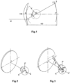
- Figure 1 shows a diagram of a lens/eye optical system seen from the side, and shows the definitions used in the rest of the description based on an example of a progressive multifocal ophthalmic lens having a front complex surface.
- the center of rotation of the eye is called Q'.
- the axis Q'F' shown in the figure by the dot/dash line is the horizontal axis passing through the center of rotation of the eye Q' and extending in front of the wearer; in other words the axis Q'F' corresponds to the primary viewing direction.
- This axis intersects the front face of the lens at a point called the fitting cross CM.
- the fitting cross is marked on lenses in order to allow them to be positioned by an optician.
- the fitting cross is generally located 4 mm above the geometric center of the front face of the lens.
- An apex sphere also called vertex sphere, with center Q' and radius q', is defined, as the sphere that cuts the rear face of the lens at the point O corresponding to the intersection by the axis Q'F' of the rear face of the lens.
- a value of the radius q' of 25.5 mm corresponds to a standard value and provides satisfactory results when the lenses are worn.
- a given viewing direction-shown by the solid line in FIG. 1 corresponds to a position of the eye rotating about Q' and to a point J on the apex sphere.
- a viewing direction may also be identified, in spherical coordinates, by two angles ⁇ and ⁇ , in the so called Fick system.
- the angle ⁇ is the angle between the Q'F' axis and the projection of the straight line Q'J on the vertical plane containing the Q'F' axis, this angle appearing in the diagram of figure 1 .
- the angle ⁇ is the angle between the Q'F' axis and the projection of the straight line Q'J on the horizontal plane containing the Q'F' axis.
- a given viewing direction therefore corresponds to a point J on the apex sphere or to a coordinate pair ( ⁇ , ⁇ ).
- the image of a point M in the object space, located at a given object distance, is formed between two points S and T corresponding to minimum and maximum distances JS and JT (which would be the sagittal and tangential focal lengths in the case of surfaces of revolution and of a point M at infinity).
- the image of a point in the object space at infinity is formed, on the Q'F' axis, at the point F'.
- the points Sand T are coincident, which amounts to stating that the lens is locally spherical in the primary viewing direction.
- the distance D is the rear frontal plane of the lens.
- Figures 2 and 3 show perspective diagrams of a lens/eye system.
- the points J and O are then coincident.
- Figure 3 shows the position of the eye and the reference frame that is associated therewith in a direction ( ⁇ , ⁇ ).
- FIGS. 2 and 3 Shown in figures 2 and 3 are a fixed reference frame ⁇ x,y,z ⁇ and a reference frame ⁇ xm,ym,zm ⁇ associated with the eye in order to show clearly the rotation of the eye.
- the reference frame ⁇ x,y,z ⁇ has as origin the point Q' and the x-axis is the Q'F' axis-the point F' not being shown in FIGS. 2 and 3 and passes through the point O.
- This axis is directed from the lens to the eye in correspondence with the direction of measurement of the astigmatism axis.
- the ⁇ y,z ⁇ plane is the vertical plane.
- the y-axis is vertical and directed upwards.
- the z-axis is horizontal, the reference frame being a direct orthonormal coordinate system.
- the reference frame ⁇ xm,ym,zm ⁇ associated with the eye has the point Q' as center.
- the xm axis is defined by the viewing direction JQ', and coincides with the ⁇ x,y,z ⁇ reference frame in the case of the primary viewing direction.
- Listing's law gives the relationships between the ⁇ x,y,z ⁇ and ⁇ xm,ym,zm ⁇ coordinate systems for each viewing direction-see Le Grand, Optique Physiodefinite, Volume 1, published by Revue d'Optique, Paris 1965 .
- the section of the lens may be drawn in the (O,x,y) plane defined with reference to figure 2 .
- the tangent to this curve at the point O is inclined to the (O,y) axis at an angle called the pantoscopic angle.
- An object point M at an object distance given by the ergorama is considered for a gaze direction ( ⁇ , ⁇ ).
- the ergorama is a function associating to each gaze direction the usual distance of an object point.
- the object point is at infinity.
- the object distance is of the order of 30 to 50 cm.
- the object proximity can be considered as the inverse of the distance between the object point and the front surface of the lens, on the corresponding light ray.
- This definition corresponds to the astigmatism of a ray beam created by the lens.
- the prescription in ophthalmic field may comprise, in addition to the power prescription, an astigmatism prescription.
- a prescription is composed of an axis value (in degrees) and a module value (in diopters).
- the module value represents the difference between the maximal and minimal power in a given direction allowing to correct the visual default of a wearer.
- the axis represents the orientation of one of the two powers versus a reference axis and following a given rotation direction.
- TABO convention may be used. In this convention the reference axis is horizontal and the rotation direction is counterclockwise when looking at the wearer.
- a 45° axis corresponds to an axis orientated obliquely linking, when looking at the wearer, the upper right quadrant to the lower left quadrant.
- Such an astigmatism prescription is measured for the wearer in far vision.
- the term 'astigmatism' is used to refer to the couple (module, axis). That term is sometimes used to designate simply the module.
- the skilled person easily understands what it refers to depending on the context.
- the skilled person is also aware that the power/astigmatism prescription for a wearer is commonly described with the terms sphere, cylinder and axis.
- the displaying method comprises at least the following steps:
- At least one optical parameter relative to the prescription for an eye of the person is provided.
- the optical parameters may be relative to a dioptric power, an astigmatism and an axis of the eye of the person, for example sphere, cylinder and axis of the eye of the person.
- At least three optical parameter are provided: sphere, cylinder and axis of the eye of the person.
- optical parameters relative to the prescription of the eye of the person may advantageously be measured beforehand by an eye care practitioner like an optometrist and then provided.
- the optical parameters relative to the prescription of the eye may be stored on a memory.
- a plurality of initial sub-images is provided during the sub-images providing step S12.
- Each initial sub-image corresponds to at least a part of the image to be displayed on the retina of the eye.
- a plurality of light beams is provided.
- the light beams are configured to be focused substantially in the plane of a pupil of the eye at a plurality of corresponding different positions also called "focusing points".
- the light beams are focused substantially in the plane means that the light beams are focused at a maximum distance of 10 mm from the plane of the pupil ensuring the sharp display of images on the retina.
- each light beam is configured to carry an associated sub-image.
- each sub-image is carried by an associated light beam focused substantially in the plane of the pupil of the eye.
- each focusing point of the pupil acts as a picoprojector which emits light towards the retina.
- the focusing of a plurality of light beams in the plane of a pupil of the eye at different positions allows increasing the size of the eye motion box (EMB) and is the basis of pupil extension.
- EMB eye motion box
- an adapted head-mounted display device is a head-mounted display device configured for displaying an image comprising at least providing a plurality of light beams, each carrying a sub-image and the light beams being adapted to focus substantially in the plane of a pupil of the eye at a plurality of corresponding different positions.
- US 2016/033771 A1 or WO 2018/091984 A1 both disclose such an adapted head mounted device.
- the operating principle of the head-mounted display device of US2016/033771 A1 is based on picoprojectors whose emitted light is reflected towards the eye by a holographic mirror. More precisely, this light is focused substantially in the plane of the wearer's pupil (see figures 2A and 2B of US2016/033771 A1 ). This results in a very small eye motion box.
- the head-mounted display device disclosed in WO2018/091984 A1 is based on a light field display (LFD).
- LFD light field display
- the invention relates to a display device adapted to provide a plurality of light beams configured to be focused substantially in the plane of a pupil of the eye at a plurality of corresponding different positions, each light beam being configured to carry an associated sub-image and adapted to execute at least the following steps:
- the initial sub-image is adapted based on the at least one provided optical parameter and on the corresponding focused position of the light beam configured to carry the sub-image to form an adapted sub-image during the adapting step S16.
- each sub-image is calculated according to the wearer's needs, i.e. according to the eye's prescription.
- Figure 5 illustrates the resulting images as seen by persons having different visual defects in the case where three sharp sub-images are displayed and are the same, i.e. a cross localized at the same position in each image.
- the three corresponding focusing points are equally distant from the centre of the pupil, and equally distant from each other.
- the person If the person is emmetropic, the person sees a single cross in his/her central vision as illustrated on the left of the figure 5 (Case A). But if the person is myopic or hyperopic, the person sees three distinct crosses, as illustrated at the center of the figure 5 (Case B), whose relative distance is a function of its spherical prescription. Finally, if the person is astigmatic, the person sees also three distinct crosses, as shown on the left of figure 5 (Case C), whose relative horizontal and vertical distances are linked to its cylindrical prescription.
- each sub-image should be calculated according to the eye's prescription of the person such that the person having visual defects sees a single cross on its retina in the same manner as an emmetropic person.
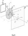
- FIGS. 6 to 9 illustrating a picoprojector 10 emitting two light rays 12, 14 (only two for simplicity's sake) crossing an optical system 16, represented by the black brackets, towards an eye 20 comprising a pupil 22 and a retina 24.
- Figures 6 and 7 relate to an emmetropic eye while figures 8 and 9 relate to an ametropic eye, for example a myopic eye.
- the optical system 16 is configured to focus the light rays emitted by the picoprojector substantially in the plane of the pupil 22.
- both light rays 12, 14 focus at the centre of the eye pupil and then form two points A' and B' on the retina 24.
- the relative position of each sub-image in the image to be displayed is pre-compensated during the adapting step S16.
- Adapting the relative position of the sub-image in the image to be displayed comprises:
- a horizontal angular position of the sub-image carried by the associated light beam is adapted based on the at least one provided optical parameter and on the corresponding focused position of the associated light beam.
- a vertical angular position of the sub-image carried by the associated light beam is adapted based on the provided optical parameters and on the corresponding focused position of the associated light beam during the vertical adapting step S24.
- a ray directed by wave vector k in coming from the half space in front of the eye and hitting the plane of the pupil 22 (Oxy) at point M is refracted into a wave vector k out by the phase function of the eye when crossing the eye of the pupil and hits the retina 24 at point P.
- Point M corresponds to a "focusing point”
- the sum of k in vectors correspond to the image content, represented by a square frame 30 in figure 10 .
- the sum of all points P corresponding to all vectors km depict the image generated on the retina.
- the difference of positions of the corresponding points P1 and P2 on the retina depends on the difference of inclination of these rays and on the differences of positions of the focusing points M1 and M2 on the pupil and not on the absolute positions of M1 and M2 on the pupil.
- the simultaneous displacement of the focusing points M1 and M2, with the same incident ray directions only results in a shift of P1 and P2 on the retina.
- the focused position in the plane of the pupil of the eye may be determined for each light beam during a preliminary calibration step.
- the focused positions of the plurality of light beams are advantageously regularly distant from each other in the plane of the pupil of the eye.
- each adapted sub-image carried by the associated light beam is displayed on the retina of the person.
- Figure 11 illustrates such method for displaying a sharp image on a retina of an eye of an ametropic person, for example a myopic person.
- an image content to be displayed (represented by a square frame 30 in figure 10 ) comprises two discs, one black and one white, aligned vertically.
- a first light beam 42 carries an associated sub-image represented by a square frame 46 and a second light beam carries an associated sub-image represented by a square frame 48.
- Each sub-image is calculated and adapted according to the prescription of the eye of the person and on the corresponding focused position of the light beam.
- the content of the first second image and the second sub-image in their frame are vertically offset from each other allowing the properly superimposition on the retina of the first and second sub-images coming from the focusing points M1 and M2.
- the adapted sub-images may be displayed sequentially or simultaneously on the retina of the person.
- a wavelength of at least one of the plurality of light beams differs from a wavelength of at least one other of the plurality of light beams.
- the wavelengths are very close to each other so that the person cannot perceive a difference in the image color.
- such method allows customizing a head-mounted display device to the user's viewing ability.
- such method allows a pre-compensation of the image to be displayed on the retina of the user based on the prescription of the eye of the user, so as to display a sharp image on the retina of the user.
- a single head-mounted device could be used by different persons having different prescription, the image to be displayed on the retina of each person being corrected based on a prescription of the eye of the person determined by the same head-mounted device.
- this method is preferably implemented using a head-mounted device adapted to at least display a plurality of sharp images on the retina of the eye of the person, the plurality of images being carried by a plurality of light beams focused substantially in the plane of the pupil of the eye at different positions.
- a head-mounted device adapted to at least display a plurality of sharp images on the retina of the eye of the person, the plurality of images being carried by a plurality of light beams focused substantially in the plane of the pupil of the eye at different positions.
- the head mounted display devices disclosed in US 2016/033771 A1 or in WO 2018/091984 A1 may be used to implement the method according to the invention.
- a computer program product may be stored in a memory of the head mounted display device, the computer program product comprising one or more stored sequences of instructions that are accessible to a processor of the head mounted display device and which, when executed by the processor, causes the processor to carry out steps of the method according to the invention.
- the optical parameters relative to the prescription of the eye of the person may advantageously be measured beforehand and provided by an eye care practitioner or stored on a memory of the head-mounted device during the parameter providing step S10, the optical parameters relative to the prescription of the eye of the person may advantageously be provided by using same adapted head mounted device to determine them.
- a method for determining optical parameters of an eye of a person comprises at least the following steps:
- each sharp image is displayed on a retina of the eye of the person carried by three light beams.
- each sharp image is carried by an associated light beam focused substantially in the plane of a pupil of the eye.
- the three light beams are focused substantially in the plane of the pupil of the eye at different positions also called "focusing points".
- each focusing point of the pupil acts as a picoprojector which emits light towards the retina.
- the focusing of a plurality of light beams in the plane of a pupil of the eye at different positions allows increasing the size of the eye motion box (EMB) and is the basis of pupil extension.
- EMB eye motion box
- Such displaying step S32 may be implemented using a head-mounted display device as disclosed in US2016/033771 A1 or WO2018/091984 A1 .
- Each of the three images displayed during the displaying step S2 comprises a target.
- the target is a spot or a one-dimensional image or a two-dimensional image.
- the target is for example a symbol or a symbol like a cross as illustrated on figures 5 .
- a parameter of the target in each image is adapted based on feedback of the person relative to the change of the parameter of the target in the image during the step S34.
- the parameter of the target in each image is modified and the person provides his/her feedback relative to this change.
- the feedback of the person is preferably a vocal feedback, for example provided by answering to questions, for example asking the person if the targets projected on his/her retina are closer or further to each other from an iteration to the following one or other similar questions.
- the feedback of the person may be a haptic feedback.
- the adapted parameter of the target is preferably the relative position of the target in each image.
- the step S34 for adapting a parameter of the target in each image comprises at least a step S42 for adapting a horizontal position of the target of an image and a step S44 for adapting a vertical position of the target of an image.
- the horizontal angular position of the target of an image carried by one of the light beams is adapted until the target of the image and the target of another image carried by another of the light beams are seen by the person with the same horizontal position in the displayed images on the retina of the eye.
- the vertical angular position of the target of an image carried by one of the light beams is adapted until the target of the image and the target of another image carried by another of the light beams are seen by the person with the same vertical position in the displayed images on the retina of the eye.
- the values of horizontal and vertical angular position of the target in the images are changed at each iteration to the response of the person when asked if two points of the target projected on his retina are closer or further to each other from an iteration to the following one and this until both targets are seen superimposed by the person, i.e. with the same vertical position and the same horizontal position in the displayed images on the retina of the eye.
- these points can correspond to the center of symbols like crosses for instance.
- the crosses can be shifted pixel by pixel in the horizontal and/or in the vertical directions at each iteration.
- such method does not require the eye to be totally motionless in relation to the focusing points.
- the only requirement is that the focusing points are contained in the eye's pupil.
- the displaying step S32 and the adapting step S34 may be carried out sequentially, i.e. for two of the three light beams and then repeated when the third light beam is added.
- two sharp images are firstly displayed on the retina of the eye of the person carried by two light beams.
- a parameter of the target in each image is adapted based on feedback of the person relative to the change of the parameter of the target in the image during the step S34, preferably until the targets of both images are seen by the person with the same position in the displayed images on the retina of the eye.
- the third sharp image is also displayed on the retina carried by a third light beam and a parameter of the target in the third image is adapted based on feedback of the person relative to the change of the parameter of the target in the image during the step S34, preferably until the targets of the third image and one of the first images are seen by the person with the same position in the displayed images on the retina of the eye.
- the optical parameter of the person's eye is determined based on the adaption of the parameter of the target in each image.
- the optical parameters of the person's eye can be determined.
- the optical parameters of the person's eye can be determined.
- the initial position of the target in the images corresponds to the setting of the display device for an emmetropic eye.
- the final position of the target in the images corresponds to the setting of the display device when adapted to a non-emmetropic person, i.e. when the person sees both targets superimposed.
- the position of the focusing points can be beforehand determined during a calibration step.
- models other than the Prentice's law can be used to determine the optical parameters of the eye of the person.
- the determination of the sphere only, if the cylinder is null requires only the display of two sharp images on the retina of the eye carried by two light beams focused at two different points in the plane of the pupil of the eye.
- the method can be generalized to other display device configured to display a plurality of sharp images on the retina of an eye carried by a plurality of associated light beams focused in a plurality of different points in the plane of a pupil of the eye and wherein the focusing points are not equally distant from the center of the eye's pupil and/or not equally distant from each other.
- the position of the focusing points should be beforehand determined during a calibration step.
- another embodiment of the determining method differs from the previous one in that the adapted parameter of the target is the size of the target in each image instead of the relative position of the target in each image.
- the position and the size of the target is the same in each displayed image initially.
- the step S34 for adapting a parameter of the target in each image comprises a step S46 for adapting in a horizontal direction and a step S48 for adapting in a vertical direction.
- the size of the target of an image carried by one of the light beams is adapted in a horizontal direction until the target of the image and the target of another image carried by another of the light beams are seen by the person touching each other in the horizontal direction in the displayed images on the retina of the eye.
- the size of the target of an image carried by one of the light beams is adapted in a vertical direction until the target of the image and the target of another image carried by another of the light beams are seen by the person touching each other in the vertical direction in the displayed images on the retina of the eye.
- such determining method is preferably implemented using a head-mounted device adapted to at least display a plurality of sharp images on the retina of the eye of the person, the plurality of images being carried by a plurality of light beams focused substantially in the plane of the pupil of the eye at different positions.
- a computer program product may be stored in a memory of the head mounted display device, the computer program product comprising one or more stored sequences of instructions that are accessible to a processor of the head mounted display device and which, when executed by the processor, causes the processor to carry out steps of the method according to the invention and as described hereinbefore.
- the method according to the invention allows advantageously customizing a head-mounted display device to the user's viewing ability. Indeed, such method allows a pre-compensation of the image to be displayed on the retina of the user based on the prescription of the eye of the user, so as to display a sharp image on the retina of the user ensuring a use of the head-mounted display device optimized for the user.
- a single head-mounted device could be used by different persons having different prescription, the image to be displayed on the retina of each person being corrected based on a prescription of the eye of the person determined by the same head-mounted device.
Landscapes
- Life Sciences & Earth Sciences (AREA)
- Health & Medical Sciences (AREA)
- Physics & Mathematics (AREA)
- Engineering & Computer Science (AREA)
- Medical Informatics (AREA)
- Molecular Biology (AREA)
- Ophthalmology & Optometry (AREA)
- Veterinary Medicine (AREA)
- Biomedical Technology (AREA)
- Heart & Thoracic Surgery (AREA)
- Public Health (AREA)
- Biophysics (AREA)
- Surgery (AREA)
- Animal Behavior & Ethology (AREA)
- General Health & Medical Sciences (AREA)
- General Physics & Mathematics (AREA)
- Optics & Photonics (AREA)
- Computer Hardware Design (AREA)
- Theoretical Computer Science (AREA)
- Eye Examination Apparatus (AREA)
Claims (15)
- Verfahren zur Anzeige eines scharfen Bildes auf einer Netzhaut (24) eines Auges der Person, wobei die Person eine Verordnung für das Auge der Person hat, wobei das Verfahren umfasst:- Bereitstellen von mindestens einem optischen Parameter relativ zu der Verordnung für das Auge der Person;- Bereitstellen einer Vielzahl von anfänglichen Teilbildern, wobei jedes anfängliche Teilbild mindestens einem Teil des anzuzeigenden Bildes entspricht;- Bereitstellen einer Vielzahl von Lichtstrahlen (12, 14), die ausgestaltet ist, um im Wesentlichen in der Ebene einer Pupille (22) des Auges an einer Vielzahl von entsprechenden unterschiedlichen Positionen (42, 44) fokussiert zu werden, wobei jeder Lichtstrahl ausgestaltet ist, um ein zugehöriges Teilbild zu tragen;- für jedes Teilbild Adaptieren des Teilbildes basierend auf dem mindestens einen bereitgestellten optischen Parameter und der entsprechenden fokussierten Position des Lichtstrahls, der ausgestaltet ist, um das Teilbild zu tragen, um ein adaptiertes Teilbild zu bilden; und- Anzeigen von jedem adaptierten Teilbild, das durch den zugehörigen Lichtstrahl getragen wird, auf der Netzhaut (24) der Person.
- Verfahren nach Anspruch 1, wobei Adaptieren des Teilbildes Adaptieren der relativen Position des Teilbildes in dem anzuzeigenden Bild umfasst.
- Verfahren nach Anspruch 2, wobei Adaptieren der relativen Position des Teilbildes in dem Bild, die angezeigt werden soll, umfasst:- Adaptieren einer horizontalen Winkelposition des Teilbildes, das durch den zugehörigen Lichtstrahl getragen wird, basierend auf dem mindestens einen bereitgestellten optischen Parameter und auf der entsprechenden fokussierten Position des zugehörigen Lichtstrahls; und- Adaptieren einer vertikalen Winkelposition des Teilbildes, das durch den zugehörigen Lichtstrahl getragen wird, basierend auf dem mindestens einen bereitgestellten optischen Parameter und auf der entsprechenden fokussierten Position des zugehörigen Lichtstrahls.
- Verfahren nach einem der vorhergehenden Ansprüche 1 bis 3, wobei das Verfahren des Weiteren für jeden Lichtstrahl von der Vielzahl der Lichtstrahlen Bestimmen der fokussierten Position in der Ebene der Pupille des Auges umfasst.
- Verfahren nach einem der vorhergehenden Ansprüche 1 bis 4, wobei die fokussierten Positionen von der Vielzahl der Lichtstrahlen in der Ebene der Pupille des Auges regelmäßig beabstandet zueinander sind.
- Verfahren nach einem der vorhergehenden Ansprüche 1 bis 5, wobei die adaptierten Teilbilder sequentiell auf der Netzhaut der Person angezeigt werden.
- Verfahren nach einem der vorhergehenden Ansprüche 1 bis 5, wobei die adaptierten Teilbilder simultan auf der Netzhaut der Person angezeigt werden.
- Verfahren nach einem der vorhergehenden Ansprüche 1 bis 7, wobei eine Wellenlänge von mindestens einem von der Vielzahl der Lichtstrahlen sich von einer Wellenlänge von mindestens einem anderen von der Vielzahl der Lichtstrahlen unterscheidet.
- Verfahren nach dem vorhergehenden Anspruch 8, wobei die Wellenlängen der Vielzahl der Lichtstrahlen in einem schmalen Band von Wellenlängen liegen, das 50 nm Breite hat.
- Verfahren nach einem der vorhergehenden Ansprüche 1 bis 9, wobei mindestens drei optische Parameter relativ zu der Verordnung für das Auge der Person bereitgestellt werden.
- Verfahren nach einem der vorhergehenden Ansprüche 1 bis 10, wobei der mindestens eine bereitgestellte optische Parameter des Auges der Person relativ zu einer dioptrischen Brechkraft, einem Astigmatismus und einer Achse des Auges der Person ist.
- Verfahren nach einem der vorhergehenden Ansprüche 1 bis 11, wobei Bereitstellen des mindestens einen optischen Parameters relativ zu der Verordnung für das Auge der Person umfasst:- Anzeigen von mindestens zwei scharfen Bildern auf einer Netzhaut des Auges der Person, wobei die mindestens zwei Bilder ein Ziel umfassen und durch zwei Lichtstrahlen getragen werden, die im Wesentlichen in der Ebene einer Pupille des Auges an mindestens zwei unterschiedlichen Positionen fokussiert werden;- Adaptieren eines Parameters des Ziels in jedem Bild basierend auf Rückmeldung der Person relativ zu der Änderung des Parameters des Ziels in dem Bild; und- Bestimmen des mindestens einen optischen Parameters des Auges der Person basierend auf der Adaptierung des Parameters des Ziels in jedem Bild.
- Am Kopf angebrachte ("Head-mounted") Vorrichtung, umfassend eine Vielzahl von Picoprojektoren (10), die adaptiert ist, um eine Vielzahl von Lichtstrahlen (12, 14) bereitzustellen, die ausgestaltet ist, um im Wesentlichen in der Ebene einer Pupille (22) des Auges an einer Vielzahl von entsprechenden unterschiedlichen Positionen (42, 44) fokussiert zu werden, wobei jeder Lichtstrahl ausgestaltet ist, um ein zugehöriges Teilbild zu tragen, und einen Prozessor, der adaptiert ist, um mindestens die Schritte des Verfahrens gemäß Anspruch 1 auszuführen.
- Computerprogrammprodukt, umfassend eine oder mehrere gespeicherte Sequenzen von Anweisungen, die einem Prozessor zugänglich sind, und die bei Ausführung durch den Prozessor bewirken, dass der Prozessor mindestens die Schritte gemäß Anspruch 1 unter Verwendung der Vorrichtung nach 13 ausführt.
- Computerlesbares Medium, das eine oder mehrere Sequenzen von Anweisungen des Computerprogrammprodukts gemäß Anspruch 14 trägt.
Applications Claiming Priority (2)
| Application Number | Priority Date | Filing Date | Title |
|---|---|---|---|
| EP20305116 | 2020-02-07 | ||
| PCT/EP2021/052926 WO2021156503A1 (en) | 2020-02-07 | 2021-02-08 | Method for displaying a sharp image on a retina of an eye of the person |
Publications (2)
| Publication Number | Publication Date |
|---|---|
| EP4100780A1 EP4100780A1 (de) | 2022-12-14 |
| EP4100780B1 true EP4100780B1 (de) | 2024-11-20 |
Family
ID=69784356
Family Applications (1)
| Application Number | Title | Priority Date | Filing Date |
|---|---|---|---|
| EP21702691.3A Active EP4100780B1 (de) | 2020-02-07 | 2021-02-08 | Verfahren zur anzeige eines scharfen bildes auf einer netzhaut eines auges einer person |
Country Status (4)
| Country | Link |
|---|---|
| US (1) | US20230057657A1 (de) |
| EP (1) | EP4100780B1 (de) |
| CN (1) | CN115151853B (de) |
| WO (1) | WO2021156503A1 (de) |
Cited By (1)
| Publication number | Priority date | Publication date | Assignee | Title |
|---|---|---|---|---|
| US12293016B2 (en) | 2018-10-22 | 2025-05-06 | Evolution Optiks Limited | Light field device, pixel rendering method therefor, and adjusted vision perception system and method using same |
Families Citing this family (1)
| Publication number | Priority date | Publication date | Assignee | Title |
|---|---|---|---|---|
| KR102723374B1 (ko) * | 2016-07-25 | 2024-10-29 | 매직 립, 인코포레이티드 | 광 필드 프로세서 시스템 |
Citations (2)
| Publication number | Priority date | Publication date | Assignee | Title |
|---|---|---|---|---|
| US10444508B2 (en) * | 2014-12-26 | 2019-10-15 | Cy Vision Inc. | Apparatus for generating a coherent beam illumination |
| EP3296797B1 (de) * | 2013-03-25 | 2019-11-06 | North Inc. | Verfahren zur anzeige eines projizierten bildes aus einer am kopf getragenen anzeige mit mehrfachen ausgangspupillen |
Family Cites Families (8)
| Publication number | Priority date | Publication date | Assignee | Title |
|---|---|---|---|---|
| FR2753805B1 (fr) | 1996-09-20 | 1998-11-13 | Essilor Int | Jeu de lentilles ophtalmiques multifocales progressives |
| KR20070064319A (ko) * | 2004-08-06 | 2007-06-20 | 유니버시티 오브 워싱톤 | 가변 응시 시거리 주사 광 디스플레이 |
| EP3108444A4 (de) * | 2014-02-19 | 2017-09-13 | Evergaze, Inc. | Vorrichtung und verfahren zur verbesserung, verstärkung oder erhöhung optimierung der sehkraft |
| US10203762B2 (en) * | 2014-03-11 | 2019-02-12 | Magic Leap, Inc. | Methods and systems for creating virtual and augmented reality |
| NZ773818A (en) * | 2015-03-16 | 2022-07-29 | Magic Leap Inc | Methods and systems for diagnosing and treating health ailments |
| CA3109499C (en) * | 2015-04-22 | 2024-11-19 | Gentex Corporation | METHODS AND DEVICES FOR CORRECTING OPTICAL ABERRATION |
| KR102723374B1 (ko) | 2016-07-25 | 2024-10-29 | 매직 립, 인코포레이티드 | 광 필드 프로세서 시스템 |
| AU2017360746B2 (en) | 2016-11-15 | 2022-07-28 | Creal Sa | Near-eye sequential light-field projector with correct monocular depth cues |
-
2021
- 2021-02-08 EP EP21702691.3A patent/EP4100780B1/de active Active
- 2021-02-08 CN CN202180008353.4A patent/CN115151853B/zh active Active
- 2021-02-08 US US17/760,178 patent/US20230057657A1/en active Pending
- 2021-02-08 WO PCT/EP2021/052926 patent/WO2021156503A1/en not_active Ceased
Patent Citations (2)
| Publication number | Priority date | Publication date | Assignee | Title |
|---|---|---|---|---|
| EP3296797B1 (de) * | 2013-03-25 | 2019-11-06 | North Inc. | Verfahren zur anzeige eines projizierten bildes aus einer am kopf getragenen anzeige mit mehrfachen ausgangspupillen |
| US10444508B2 (en) * | 2014-12-26 | 2019-10-15 | Cy Vision Inc. | Apparatus for generating a coherent beam illumination |
Cited By (2)
| Publication number | Priority date | Publication date | Assignee | Title |
|---|---|---|---|---|
| US12293016B2 (en) | 2018-10-22 | 2025-05-06 | Evolution Optiks Limited | Light field device, pixel rendering method therefor, and adjusted vision perception system and method using same |
| US12293015B2 (en) | 2018-10-22 | 2025-05-06 | Evolution Optiks Limited | Light field vision testing device, adjusted pixel rendering method therefor, and vision testing system and method using same |
Also Published As
| Publication number | Publication date |
|---|---|
| CN115151853A (zh) | 2022-10-04 |
| EP4100780A1 (de) | 2022-12-14 |
| WO2021156503A1 (en) | 2021-08-12 |
| CN115151853B (zh) | 2025-06-10 |
| WO2021156503A9 (en) | 2022-06-09 |
| US20230057657A1 (en) | 2023-02-23 |
Similar Documents
| Publication | Publication Date | Title |
|---|---|---|
| US10958898B2 (en) | Image creation device, method for image creation, image creation program, method for designing eyeglass lens and method for manufacturing eyeglass lens | |
| EP3126901B1 (de) | Verfahren zur berechnung eines optischen systems nach einer bestimmten brillenfassung | |
| JP5102289B2 (ja) | 眼鏡レンズを最適化および/または製造するための方法 | |
| US11150476B2 (en) | Method for providing a display unit for an electronic information device | |
| US9791718B2 (en) | Progressive multifocal ophthalmic lens designed to inhibit progressive myopia of the wearer | |
| JP5893553B2 (ja) | 眼鏡レンズを決定する方法 | |
| JP6043731B2 (ja) | 目標光学関数の決定方法 | |
| CA2873522C (en) | A process for determining a pair of progressive ophthalmic lenses | |
| CN102460277A (zh) | 单视眼镜片 | |
| EP4100780B1 (de) | Verfahren zur anzeige eines scharfen bildes auf einer netzhaut eines auges einer person | |
| US10088692B1 (en) | Free-space lens design method | |
| EP3861923B1 (de) | Verfahren zur bestimmung mindestens eines parameters eines auges einer person | |
| EP3304180B1 (de) | Verfahren zur modifizierung eines nichtdioptrischen parameters eines optischen systems | |
| JP3347514B2 (ja) | 眼光学系のシミュレーション装置 |
Legal Events
| Date | Code | Title | Description |
|---|---|---|---|
| STAA | Information on the status of an ep patent application or granted ep patent |
Free format text: STATUS: UNKNOWN |
|
| STAA | Information on the status of an ep patent application or granted ep patent |
Free format text: STATUS: THE INTERNATIONAL PUBLICATION HAS BEEN MADE |
|
| PUAI | Public reference made under article 153(3) epc to a published international application that has entered the european phase |
Free format text: ORIGINAL CODE: 0009012 |
|
| STAA | Information on the status of an ep patent application or granted ep patent |
Free format text: STATUS: REQUEST FOR EXAMINATION WAS MADE |
|
| 17P | Request for examination filed |
Effective date: 20220623 |
|
| AK | Designated contracting states |
Kind code of ref document: A1 Designated state(s): AL AT BE BG CH CY CZ DE DK EE ES FI FR GB GR HR HU IE IS IT LI LT LU LV MC MK MT NL NO PL PT RO RS SE SI SK SM TR |
|
| DAV | Request for validation of the european patent (deleted) | ||
| DAX | Request for extension of the european patent (deleted) | ||
| P01 | Opt-out of the competence of the unified patent court (upc) registered |
Effective date: 20230525 |
|
| GRAP | Despatch of communication of intention to grant a patent |
Free format text: ORIGINAL CODE: EPIDOSNIGR1 |
|
| STAA | Information on the status of an ep patent application or granted ep patent |
Free format text: STATUS: GRANT OF PATENT IS INTENDED |
|
| INTG | Intention to grant announced |
Effective date: 20240712 |
|
| RIN1 | Information on inventor provided before grant (corrected) |
Inventor name: ROPTIN, VINCENT Inventor name: BOUTINON, STEPHANE Inventor name: PELOUX, MARIUS |
|
| GRAS | Grant fee paid |
Free format text: ORIGINAL CODE: EPIDOSNIGR3 |
|
| GRAA | (expected) grant |
Free format text: ORIGINAL CODE: 0009210 |
|
| STAA | Information on the status of an ep patent application or granted ep patent |
Free format text: STATUS: THE PATENT HAS BEEN GRANTED |
|
| AK | Designated contracting states |
Kind code of ref document: B1 Designated state(s): AL AT BE BG CH CY CZ DE DK EE ES FI FR GB GR HR HU IE IS IT LI LT LU LV MC MK MT NL NO PL PT RO RS SE SI SK SM TR |
|
| REG | Reference to a national code |
Ref country code: GB Ref legal event code: FG4D |
|
| REG | Reference to a national code |
Ref country code: CH Ref legal event code: EP |
|
| REG | Reference to a national code |
Ref country code: DE Ref legal event code: R096 Ref document number: 602021022053 Country of ref document: DE |
|
| REG | Reference to a national code |
Ref country code: IE Ref legal event code: FG4D |
|
| REG | Reference to a national code |
Ref country code: LT Ref legal event code: MG9D |
|
| REG | Reference to a national code |
Ref country code: NL Ref legal event code: MP Effective date: 20241120 |
|
| PG25 | Lapsed in a contracting state [announced via postgrant information from national office to epo] |
Ref country code: PT Free format text: LAPSE BECAUSE OF FAILURE TO SUBMIT A TRANSLATION OF THE DESCRIPTION OR TO PAY THE FEE WITHIN THE PRESCRIBED TIME-LIMIT Effective date: 20250320 Ref country code: IS Free format text: LAPSE BECAUSE OF FAILURE TO SUBMIT A TRANSLATION OF THE DESCRIPTION OR TO PAY THE FEE WITHIN THE PRESCRIBED TIME-LIMIT Effective date: 20250320 Ref country code: HR Free format text: LAPSE BECAUSE OF FAILURE TO SUBMIT A TRANSLATION OF THE DESCRIPTION OR TO PAY THE FEE WITHIN THE PRESCRIBED TIME-LIMIT Effective date: 20241120 |
|
| PG25 | Lapsed in a contracting state [announced via postgrant information from national office to epo] |
Ref country code: FI Free format text: LAPSE BECAUSE OF FAILURE TO SUBMIT A TRANSLATION OF THE DESCRIPTION OR TO PAY THE FEE WITHIN THE PRESCRIBED TIME-LIMIT Effective date: 20241120 Ref country code: NL Free format text: LAPSE BECAUSE OF FAILURE TO SUBMIT A TRANSLATION OF THE DESCRIPTION OR TO PAY THE FEE WITHIN THE PRESCRIBED TIME-LIMIT Effective date: 20241120 |
|
| REG | Reference to a national code |
Ref country code: AT Ref legal event code: MK05 Ref document number: 1744098 Country of ref document: AT Kind code of ref document: T Effective date: 20241120 |
|
| PG25 | Lapsed in a contracting state [announced via postgrant information from national office to epo] |
Ref country code: BG Free format text: LAPSE BECAUSE OF FAILURE TO SUBMIT A TRANSLATION OF THE DESCRIPTION OR TO PAY THE FEE WITHIN THE PRESCRIBED TIME-LIMIT Effective date: 20241120 |
|
| PG25 | Lapsed in a contracting state [announced via postgrant information from national office to epo] |
Ref country code: ES Free format text: LAPSE BECAUSE OF FAILURE TO SUBMIT A TRANSLATION OF THE DESCRIPTION OR TO PAY THE FEE WITHIN THE PRESCRIBED TIME-LIMIT Effective date: 20241120 |
|
| PG25 | Lapsed in a contracting state [announced via postgrant information from national office to epo] |
Ref country code: NO Free format text: LAPSE BECAUSE OF FAILURE TO SUBMIT A TRANSLATION OF THE DESCRIPTION OR TO PAY THE FEE WITHIN THE PRESCRIBED TIME-LIMIT Effective date: 20250220 |
|
| PG25 | Lapsed in a contracting state [announced via postgrant information from national office to epo] |
Ref country code: AT Free format text: LAPSE BECAUSE OF FAILURE TO SUBMIT A TRANSLATION OF THE DESCRIPTION OR TO PAY THE FEE WITHIN THE PRESCRIBED TIME-LIMIT Effective date: 20241120 Ref country code: LV Free format text: LAPSE BECAUSE OF FAILURE TO SUBMIT A TRANSLATION OF THE DESCRIPTION OR TO PAY THE FEE WITHIN THE PRESCRIBED TIME-LIMIT Effective date: 20241120 Ref country code: GR Free format text: LAPSE BECAUSE OF FAILURE TO SUBMIT A TRANSLATION OF THE DESCRIPTION OR TO PAY THE FEE WITHIN THE PRESCRIBED TIME-LIMIT Effective date: 20250221 |
|
| PG25 | Lapsed in a contracting state [announced via postgrant information from national office to epo] |
Ref country code: PL Free format text: LAPSE BECAUSE OF FAILURE TO SUBMIT A TRANSLATION OF THE DESCRIPTION OR TO PAY THE FEE WITHIN THE PRESCRIBED TIME-LIMIT Effective date: 20241120 |
|
| PG25 | Lapsed in a contracting state [announced via postgrant information from national office to epo] |
Ref country code: RS Free format text: LAPSE BECAUSE OF FAILURE TO SUBMIT A TRANSLATION OF THE DESCRIPTION OR TO PAY THE FEE WITHIN THE PRESCRIBED TIME-LIMIT Effective date: 20250220 |
|
| PG25 | Lapsed in a contracting state [announced via postgrant information from national office to epo] |
Ref country code: SM Free format text: LAPSE BECAUSE OF FAILURE TO SUBMIT A TRANSLATION OF THE DESCRIPTION OR TO PAY THE FEE WITHIN THE PRESCRIBED TIME-LIMIT Effective date: 20241120 |
|
| PG25 | Lapsed in a contracting state [announced via postgrant information from national office to epo] |
Ref country code: DK Free format text: LAPSE BECAUSE OF FAILURE TO SUBMIT A TRANSLATION OF THE DESCRIPTION OR TO PAY THE FEE WITHIN THE PRESCRIBED TIME-LIMIT Effective date: 20241120 |
|
| PG25 | Lapsed in a contracting state [announced via postgrant information from national office to epo] |
Ref country code: EE Free format text: LAPSE BECAUSE OF FAILURE TO SUBMIT A TRANSLATION OF THE DESCRIPTION OR TO PAY THE FEE WITHIN THE PRESCRIBED TIME-LIMIT Effective date: 20241120 |
|
| PG25 | Lapsed in a contracting state [announced via postgrant information from national office to epo] |
Ref country code: RO Free format text: LAPSE BECAUSE OF FAILURE TO SUBMIT A TRANSLATION OF THE DESCRIPTION OR TO PAY THE FEE WITHIN THE PRESCRIBED TIME-LIMIT Effective date: 20241120 |
|
| PG25 | Lapsed in a contracting state [announced via postgrant information from national office to epo] |
Ref country code: SK Free format text: LAPSE BECAUSE OF FAILURE TO SUBMIT A TRANSLATION OF THE DESCRIPTION OR TO PAY THE FEE WITHIN THE PRESCRIBED TIME-LIMIT Effective date: 20241120 |
|
| PG25 | Lapsed in a contracting state [announced via postgrant information from national office to epo] |
Ref country code: CZ Free format text: LAPSE BECAUSE OF FAILURE TO SUBMIT A TRANSLATION OF THE DESCRIPTION OR TO PAY THE FEE WITHIN THE PRESCRIBED TIME-LIMIT Effective date: 20241120 |
|
| REG | Reference to a national code |
Ref country code: DE Ref legal event code: R097 Ref document number: 602021022053 Country of ref document: DE |
|
| PG25 | Lapsed in a contracting state [announced via postgrant information from national office to epo] |
Ref country code: SE Free format text: LAPSE BECAUSE OF FAILURE TO SUBMIT A TRANSLATION OF THE DESCRIPTION OR TO PAY THE FEE WITHIN THE PRESCRIBED TIME-LIMIT Effective date: 20241120 |
|
| PG25 | Lapsed in a contracting state [announced via postgrant information from national office to epo] |
Ref country code: MC Free format text: LAPSE BECAUSE OF FAILURE TO SUBMIT A TRANSLATION OF THE DESCRIPTION OR TO PAY THE FEE WITHIN THE PRESCRIBED TIME-LIMIT Effective date: 20241120 |
|
| PLBE | No opposition filed within time limit |
Free format text: ORIGINAL CODE: 0009261 |
|
| STAA | Information on the status of an ep patent application or granted ep patent |
Free format text: STATUS: NO OPPOSITION FILED WITHIN TIME LIMIT |
|
| REG | Reference to a national code |
Ref country code: CH Ref legal event code: PL |
|
| PG25 | Lapsed in a contracting state [announced via postgrant information from national office to epo] |
Ref country code: LU Free format text: LAPSE BECAUSE OF NON-PAYMENT OF DUE FEES Effective date: 20250208 |
|
| PG25 | Lapsed in a contracting state [announced via postgrant information from national office to epo] |
Ref country code: CH Free format text: LAPSE BECAUSE OF NON-PAYMENT OF DUE FEES Effective date: 20250228 |
|
| 26N | No opposition filed |
Effective date: 20250821 |
|
| REG | Reference to a national code |
Ref country code: BE Ref legal event code: MM Effective date: 20250228 |
|
| PG25 | Lapsed in a contracting state [announced via postgrant information from national office to epo] |
Ref country code: BE Free format text: LAPSE BECAUSE OF NON-PAYMENT OF DUE FEES Effective date: 20250228 |
|
| PG25 | Lapsed in a contracting state [announced via postgrant information from national office to epo] |
Ref country code: IE Free format text: LAPSE BECAUSE OF NON-PAYMENT OF DUE FEES Effective date: 20250208 |
|
| PGFP | Annual fee paid to national office [announced via postgrant information from national office to epo] |
Ref country code: GB Payment date: 20260227 Year of fee payment: 6 |
|
| PGFP | Annual fee paid to national office [announced via postgrant information from national office to epo] |
Ref country code: DE Payment date: 20260227 Year of fee payment: 6 |
|
| PGFP | Annual fee paid to national office [announced via postgrant information from national office to epo] |
Ref country code: IT Payment date: 20260219 Year of fee payment: 6 |
|
| PGFP | Annual fee paid to national office [announced via postgrant information from national office to epo] |
Ref country code: FR Payment date: 20260225 Year of fee payment: 6 |