EP4100762B1 - Procédé de fonctionnement d'un capteur radar dans un véhicule automobile, et véhicule automobile - Google Patents
Procédé de fonctionnement d'un capteur radar dans un véhicule automobile, et véhicule automobile Download PDFInfo
- Publication number
- EP4100762B1 EP4100762B1 EP21702235.9A EP21702235A EP4100762B1 EP 4100762 B1 EP4100762 B1 EP 4100762B1 EP 21702235 A EP21702235 A EP 21702235A EP 4100762 B1 EP4100762 B1 EP 4100762B1
- Authority
- EP
- European Patent Office
- Prior art keywords
- transmission power
- radar sensor
- range
- power value
- radar
- Prior art date
- Legal status (The legal status is an assumption and is not a legal conclusion. Google has not performed a legal analysis and makes no representation as to the accuracy of the status listed.)
- Active
Links
Images

Classifications
-
- G—PHYSICS
- G01—MEASURING; TESTING
- G01S—RADIO DIRECTION-FINDING; RADIO NAVIGATION; DETERMINING DISTANCE OR VELOCITY BY USE OF RADIO WAVES; LOCATING OR PRESENCE-DETECTING BY USE OF THE REFLECTION OR RERADIATION OF RADIO WAVES; ANALOGOUS ARRANGEMENTS USING OTHER WAVES
- G01S13/00—Systems using the reflection or reradiation of radio waves, e.g. radar systems; Analogous systems using reflection or reradiation of waves whose nature or wavelength is irrelevant or unspecified
- G01S13/88—Radar or analogous systems specially adapted for specific applications
- G01S13/93—Radar or analogous systems specially adapted for specific applications for anti-collision purposes
- G01S13/931—Radar or analogous systems specially adapted for specific applications for anti-collision purposes of land vehicles
-
- G—PHYSICS
- G01—MEASURING; TESTING
- G01K—MEASURING TEMPERATURE; MEASURING QUANTITY OF HEAT; THERMALLY-SENSITIVE ELEMENTS NOT OTHERWISE PROVIDED FOR
- G01K3/00—Thermometers giving results other than momentary value of temperature
- G01K3/005—Circuits arrangements for indicating a predetermined temperature
-
- G—PHYSICS
- G01—MEASURING; TESTING
- G01S—RADIO DIRECTION-FINDING; RADIO NAVIGATION; DETERMINING DISTANCE OR VELOCITY BY USE OF RADIO WAVES; LOCATING OR PRESENCE-DETECTING BY USE OF THE REFLECTION OR RERADIATION OF RADIO WAVES; ANALOGOUS ARRANGEMENTS USING OTHER WAVES
- G01S7/00—Details of systems according to groups G01S13/00, G01S15/00, G01S17/00
- G01S7/02—Details of systems according to groups G01S13/00, G01S15/00, G01S17/00 of systems according to group G01S13/00
- G01S7/40—Means for monitoring or calibrating
- G01S7/4004—Means for monitoring or calibrating of parts of a radar system
- G01S7/4008—Means for monitoring or calibrating of parts of a radar system of transmitters
-
- G—PHYSICS
- G01—MEASURING; TESTING
- G01S—RADIO DIRECTION-FINDING; RADIO NAVIGATION; DETERMINING DISTANCE OR VELOCITY BY USE OF RADIO WAVES; LOCATING OR PRESENCE-DETECTING BY USE OF THE REFLECTION OR RERADIATION OF RADIO WAVES; ANALOGOUS ARRANGEMENTS USING OTHER WAVES
- G01S7/00—Details of systems according to groups G01S13/00, G01S15/00, G01S17/00
- G01S7/02—Details of systems according to groups G01S13/00, G01S15/00, G01S17/00 of systems according to group G01S13/00
- G01S7/40—Means for monitoring or calibrating
- G01S7/4004—Means for monitoring or calibrating of parts of a radar system
- G01S7/4008—Means for monitoring or calibrating of parts of a radar system of transmitters
- G01S7/4013—Means for monitoring or calibrating of parts of a radar system of transmitters involving adjustment of the transmitted power
Definitions
- the invention relates to a method for operating a particularly long-range radar sensor in a motor vehicle, wherein the radar sensor has a detection range directed towards the area in front of or behind the motor vehicle, is operated with a transmission power that determines a range of the radar sensor, and the radar data of the radar sensor, particularly within the radar sensor itself, are evaluated to detect objects in the detection range.
- the invention also relates to a motor vehicle.
- a short-range radar (SRR) has a maximum measuring range of up to 30 m
- MRR medium-range radar
- LRR long-range radar
- LRR Long-range radars
- radar data from a long-range radar sensor in vehicle functions of a longitudinal adaptive cruise control system (ACC system), an overtaking assistant, a lane change assistant and also for safety systems. for example, avoidance systems.
- ACC system longitudinal adaptive cruise control system
- An overtaking assistant for example, an overtaking assistant
- a lane change assistant for safety systems.
- avoidance systems for example, avoidance systems.
- Radar data, including from long-range radar sensors, are also usually used for at least partially, and in particular completely, automatic guidance of the vehicle.
- Modern radar sensors that are installed in motor vehicles to monitor the environment usually use semiconductor technologies at least in part, with transmitting chips, particularly so-called MMICs, usually being used as transmitting units to send out the radar signals.
- transmitting chips particularly so-called MMICs
- MMICs transmitting chips
- Such a transmitting chip can heat up.
- the transmission power is set to a transmission power value such that under all temperature conditions, for example in the range from -40°C to +80°C, the thermal load on the transmission chip can be represented non-destructively and usually with reserve. This leads to a reduction in the transmission power actually used compared to the transmission power that is fundamentally possible in order to enable the radar sensor to function permanently under the thermal conditions.
- long-range radar sensors LRR are now usually set to 10 dBm transmission power, although the transmission chip could deliver 13 dBm (20 mW) or modern transmission chips could even deliver 14 dBm (30 mW) transmission power.
- MRR medium-range
- LRR long-range
- EN 10 2004 017 720 A1 proposes that, in order to detect objects in the vicinity of a vehicle in a radar sensor system, the transmission power of the radar signal be controlled adaptively as a function of the actual distance to a nearest object, taking into account a functional parameter provided for a desired radar function. It can be provided that the closer the object comes, the lower the transmission power is, in order to avoid crosstalk.
- Such over-control is to be expected in particular when measurements are to be taken in the close range, for example at a distance of only a few meters, so that the teaching therein particularly concerns short-range radars (SRR), in particular also so-called near-field radars (NFR), which are intended to measure down to ranges of one meter or less.
- SRR short-range radars
- NFR near-field radars
- EN 10 2007 046 648 A1 relates to a radar sensor for detecting the traffic environment in motor vehicles.
- the radar sensor has an adjustable transmit and/or receive amplifier and an adjustment device for adjusting the transmit and/or receive gain, whereby the traffic environment is continuously assessed by an evaluation device and the adjustment device is influenced depending on the current evaluation in order to reduce the number of disturbing radar echoes from irrelevant objects, particularly in city traffic. Complicated beamforming approaches and complex modifications to the antenna arrangements are described for this purpose.
- DE 103 47 214 A1 relates to a radar system with at least one detector for special weather conditions.
- the transmission power of the radar system is controlled depending on the special weather conditions detected by the at least one detector, whereby, for example, the power is to be increased when visibility is poor.
- this would increase the so-called clutter caused by, for example, raindrops and/or snowflakes.
- the invention is therefore based on the object of enabling the earliest possible detection of objects by a radar sensor in the simplest possible manner while, in particular, maintaining continuous operation.
- the switching power of the radar sensor is increased from a first transmission power value to a second transmission power value.
- the invention is based on the finding that when examining typical journeys in a motor vehicle that has a long-range front or rear radar sensor, at least one relevant object is in the detection range of the radar sensor for the majority of the time, and to a lesser extent no (relevant) object can be detected in the detection range. It is therefore proposed that when no object, in particular no relevant object, is detected in the detection range, the transmission power of the radar sensor is increased in order to increase the detection range and thus also make smaller objects, such as motorcyclists, detectable earlier. So instead of setting the transmission power to a medium continuous power, the invention proposes to strive for dynamic transmission power control.
- the present invention now makes it possible to use high-performance radars on roads with little traffic and in areas with little (relevant) Objects increase the transmission power of the radar sensor in order to achieve early detection if a (relevant) object does appear.
- the transmission power can be reduced accordingly again.
- the transmission power is reduced from the second transmission power value to the first transmission power value again when a reduction criterion is met, with at least a first of the at least one reduction criteria checking whether an object, in particular one that meets the relevance criterion, is detected by the radar sensor.
- temperature monitoring can expediently also take place, for example by means of a temperature sensor in or on the radar sensor.
- an expedient development of the present invention provides that at least a second of the at least one reduction criterion checks whether a temperature of the radar sensor, in particular a transmission unit of the radar sensor, exceeds a first threshold value and/or a thermal reserve value carried over time on the basis of a or the measured temperature falls below a second threshold value.
- the transmission power can be increased to the second transmission power value, which can correspond in particular to the maximum performance of a transmission chip as a transmission unit, until an object is detected or a maximum temperature (first threshold) is reached or the thermal reserves are considered to be too low (second threshold).
- a particularly advantageous embodiment of the present invention provides that, when the first reduction criterion is met, the transmission power is reduced from the second transmission power value to the first transmission power value continuously or step by step, in particular depending on a distance and/or a relative speed of the detected object, such that the object, despite the reduction in the transmission power continues to be detected by the radar sensor.
- the transmission power can be gradually reduced again, whereby this is particularly advantageously done in such a way that the resulting range is equal to or greater than the distance by a tolerance value. In other words, this ensures that the object continues to be detected and can therefore be tracked (so-called "tracking").
- the thermal load on the transmission unit, in particular the transmission chip is reduced again.
- evaluated radar data used only to evaluate the switching criterion can also advantageously be supplied by a tracking algorithm within the radar sensor, in particular by a tracking unit of the control device of the radar sensor.
- a tracking unit implementing a tracking algorithm can provide information as to whether or not a (relevant) object is currently being tracked.
- a (relevant) detected object is not currently present.
- Such tracking algorithms are now usually implemented within the radar sensors themselves, which can also apply to the dynamic transmission power control described here, for which the control device of the radar sensor can have a corresponding transmission power unit or a corresponding transmission power algorithm.
- the present invention offers a particularly easy-to-implement variant of dynamic transmission power control, which can be implemented using existing means (temperature sensor, tracking algorithm) and can be implemented, for example, using only a small control loop with a few lines of code in a transmission power algorithm.
- the required information for example whether a tracking algorithm is tracking a relevant object, as well as information regarding the thermal load from a temperature sensor that is specifically assigned to the radar sensor or provided in it, already exist and only need to be queried in order to implement transmission power control in a simple manner, without the need for complex beamforming and antenna characteristic control approaches.
- the thermal load on transmitting units, particularly transmitting chips, in radar sensors has so far been set to the maximum ambient temperature of 80 to 85 °C in conjunction with the continuous transmitting power.
- 80 °C is rarely reached, since even in deserts temperatures of 50 °C and more usually only occur for short periods.
- the majority of the world is in the moderate temperature range, although temperatures would be far from the 30 °C limit for long periods of the year.
- a short-term increase in the transmitting power, until a (relevant) object appears again in the radar sensor's detection range, is therefore feasible.
- the evaluation of the switching criterion and the at least one reduction criterion relates to relevant objects, whereby it is provided that the relevance criterion is selected such that it is fulfilled for objects that are classified in such a way that they are to be taken into account by functions that use the radar data of the radar sensor.
- the classification of objects from radar data is already largely known in the prior art in order to keep the number of objects that are actually to be evaluated by the vehicle functions as low as possible and, for example, to exclude peripheral development objects and the like as far as possible. Accordingly, objects can be classified as one be classified as belonging to a relevance class.
- a relevance class can, for example, contain dynamic objects, i.e. other road users.
- Vehicle functions that use radar data from radar sensors can, for example, include ACC functions, overtaking assistance functions, lane change assistance functions, safety functions (e.g. evasive action assistance functions) and functions for at least partially automatic guidance of the motor vehicle.
- the relevance criterion can also take into account whether the corresponding vehicle function is currently active at all.
- the second transmission power value can be increased by 20 to 50%, in particular by 30%, compared to the first transmission power value and/or the range given by the second transmission power value can be increased by 30 to 70%, in particular 50%, compared to the range given by the first transmission power value.
- increasing the transmission power from 10 dBm continuous power to 13 dBm short-term power can already ensure a 50% increase in range and thus early detection of (relevant) objects.
- the transmission power is typically in the range of 10 to 14 dBm and the antenna gain is typically 15 to 21 dBi, so that even with a second transmission power value using the maximum possible transmission power, the operation is far from such a limit.
- a radar sensor with a transmitting unit designed as a transmitting chip is preferably used as the radar sensor. It can be particularly advantageous to use a temperature sensor integrated in the transmitting chip to measure a temperature of the radar sensor, specifically a temperature of the transmitting chip. While in the context of the present invention it is fundamentally possible If it is possible to use temperature measurements of the outside and/or ambient temperature for temperature monitoring, it is preferred according to the invention to use a temperature sensor in the vicinity of the transmitter chip or preferably integrated there in order to be able to monitor the thermal load on the transmitter chip as realistically as possible.
- the present invention also relates to a motor vehicle, having a particularly long-range radar sensor, wherein the radar sensor has a detection range directed towards the area in front of or behind the motor vehicle, is operated with a transmission power that determines a range of the radar sensor and also has a control device that is designed to carry out the method according to the invention.
- All embodiments and comments relating to the method according to the invention apply analogously to the motor vehicle according to the invention, so that the advantages already mentioned can also be obtained with this.
- control device can, for example, have a transmission power unit for carrying out the method according to the invention, which can, for example, receive data from a tracking unit of the control device as well as data from a temperature sensor directly and/or a temperature monitoring unit.
- a transmission power unit for carrying out the method according to the invention, which can, for example, receive data from a tracking unit of the control device as well as data from a temperature sensor directly and/or a temperature monitoring unit.
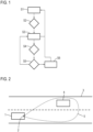
- Fig.1 shows a flow chart of an embodiment of the method according to the invention for operating a long-range radar sensor (LRR) in a motor vehicle.
- the radar sensor is aimed at the area in front of or behind the motor vehicle. Due to at least one vehicle function of the motor vehicle being active over longer periods of time, continuous operation of the radar sensor is required so that it can provide radar data for the vehicle function.
- the radar sensor itself is already designed for an initial evaluation of the radar data by classifying detected objects based on a relevance criterion that filters out objects that are not relevant to the at least one vehicle function, and tracking by a tracking algorithm takes place in a tracking unit, with tracking being limited to relevant objects.
- Relevant objects can include, for example, other road users and/or obstacles on the road.
- step S1 it is operated with a transmission power according to a first transmission power value.
- the normal operation of the radar sensor relates to the situation in which at least one relevant object is detected and tracked, which is significantly more common according to an underlying finding.
- the first transmission power value is selected in such a way that overheating of the transmission chip used as the transmission unit in the radar sensor, here an MMIC, is prevented.
- the first transmission power value results in a certain first range and a certain detection capability with regard to smaller objects, for example motorcyclists.
- step S2 it is checked whether a switching criterion is met. In this case, the switching criterion is met if no relevant objects are detected, i.e. no relevant objects are detected in the tracking unit. tracked. If the switching criterion is not met, step S1 is used using the first transmission power value, while if the switching criterion is met, the system branches to step S3, in which the transmission power is increased to a second transmission power value that is higher than the first transmission power value. In one example, the transmission power can then be increased to a maximum performance of the transmission chip, for example. If the first transmission power value is increased from 10 dBm to 13 dBm as the second transmission power value, a second range that is 50% higher than the first range can be achieved.
- the increased transmission power not only increases the range, but also the detection capability for smaller objects, so that relevant objects can be detected earlier.
- the easy-to-determine and implement increase in transmission power ensures that newly occurring relevant objects are detected as early as possible when there is no relevant object in the detection area.
- a second reduction criterion is checked, which is intended to determine whether there is a risk of overheating of the transmission chip, for example if the second transmission power value was required for longer than expected or the like. For this purpose, it can be checked whether a temperature measurement value of a temperature sensor exceeds a first threshold value and/or, if a heat balance is maintained, whether a thermal reserve falls below a second threshold value. If the second reduction criterion is met, the transmission power is reduced again, at least temporarily, to the first transmission power value, step S1.
- a first reduction criterion is checked in a step S5, which monitors whether a new relevant object was detected by the radar sensor early on due to the increased transmission power. If this is not the case, the system continues with step S3, but if this is the case, the system branches to a step S6.
- step S6 the transmission power is gradually (or alternatively continuously) reduced from the second transmission power value back to the first transmission power value, with Once this limit is reached, the system continues with step S1.
- the gradual (or alternatively continuous) reduction is carried out depending on the distance and/or the relative speed of the detected object in such a way that it is ensured that this object can continue to be detected and thus tracked. In other words, a transmission power is selected such that the range allows continuous detection of the object.
- Fig.2 and Fig.3 explain this in more detail using two traffic situations.
- Fig.2 shows a motor vehicle 1 according to the invention with a long-range front radar sensor 2 on a road 3. Another road user is coming towards him and is within the detection range 5 of the radar sensor 2. This is operated with a transmission power according to the first transmission power value, so that a rather short range is given.
- the transmission power is used according to the second transmission power value and the detection area 5' is given with a significantly increased range, for example by 50%.
- New relevant objects 6, as indicated by way of example can be detected at an early stage.
- Fig.4 shows a schematic diagram of the motor vehicle 1 according to the invention, which in this case, in addition to the long-range front radar sensor 2 already described, also comprises a long-range or medium-range rear radar sensor 7, which can forward its already pre-evaluated radar data, in particular relating to the tracking of the relevant objects, to various vehicle systems 8 which carry out vehicle functions using the radar data.
- the radar sensors 2, 7 have, in addition to an antenna arrangement 9, to which a transmitting unit 11 designed as a transmitting chip 10 and a receiving unit 12 are assigned, a control device 13 which is designed to carry out the method according to the invention.
- a control device 13 which is designed to carry out the method according to the invention.
- the A temperature sensor 14 is also integrated into the transmission chip 10, in this case an MMIC, which supplies its temperature measurement values to the control device 13.
- the control device 13 in this case always comprises a tracking unit 15 in which, as is basically known, a tracking algorithm is executed.
- the tracking unit 15 can also classify objects as relevant or not relevant, but this can also be done by a classification unit. Information about whether a relevant object 6 was detected or not, as well as the temperature measurement values of the temperature sensor 14, are forwarded to the transmission power unit 16 which specifically carries out the method according to the invention.
Landscapes
- Engineering & Computer Science (AREA)
- Radar, Positioning & Navigation (AREA)
- Remote Sensing (AREA)
- Physics & Mathematics (AREA)
- General Physics & Mathematics (AREA)
- Computer Networks & Wireless Communication (AREA)
- Electromagnetism (AREA)
- Radar Systems Or Details Thereof (AREA)
- Traffic Control Systems (AREA)
Claims (9)
- Procédé de fonctionnement d'un capteur radar (2, 7) en particulier à longue portée dans un véhicule automobile (1), dans lequel le capteur radar (2, 7) présente une zone de détection (5, 5') dirigée sur la zone située devant ou derrière le véhicule automobile (1), le capteur radar (2, 7) fonctionne avec une puissance d'émission déterminant une portée du capteur radar (2, 7) et les données de radar du capteur radar (2, 7), en particulier à l'intérieur du capteur radar (2, 7) lui-même, sont évaluées pour la détection d'objets (6) dans la zone de détection (5, 5'),
caractérisé en ce que
lors du remplissage d'un critère de commutation indiquant qu'aucun objet (6) remplissant un critère de pertinence n'a été détecté par le capteur radar (2, 7), la puissance d'émission du capteur radar (2, 7) est augmentée d'une première valeur de puissance d'émission à une seconde valeur de puissance d'émission, dans lequel le critère de pertinence est choisi de telle manière qu'il soit rempli pour des objets (6) classés comme étant à prendre en compte par des fonctions utilisant les données de radar du capteur radar (2, 7). - Procédé selon la revendication 1,
caractérisé en ce que
la puissance d'émission est de nouveau réduite lors du remplissage d'au moins un critère de diminution de la seconde valeur de puissance d'émission à la première valeur de puissance d'émission. - Procédé selon la revendication 2,
caractérisé en ce que
au moins un premier de l'au moins un critère de diminution vérifie si un objet (6), remplissant en particulier le critère de pertinence, est détecté par le capteur radar (2, 7), et/ou au moins un second de l'au moins un critère de diminution vérifie si une température du capteur radar (2, 7), en particulier d'une unité d'émission (11) du capteur radar (2, 7), dépasse une première valeur seuil et/ou une valeur de réserve thermique entraînée en raison d'une ou de la température mesurée dans le temps reste en dessous d'une seconde valeur seuil. - Procédé selon la revendication 3,
caractérisé en ce que
lors du remplissage du premier critère de diminution, la puissance d'émission est réduite de la seconde valeur de puissance d'émission à la première valeur de puissance d'émission en continu ou progressivement, en particulier en fonction d'une distance et/ou d'une vitesse relative de l'objet (6) détecté de telle manière que l'objet (6) soit en outre détecté en dépit de la réduction de la puissance d'émission par le capteur radar (2, 7). - Procédé selon la revendication 4,
caractérisé en ce que
la puissance d'émission est réduite jusqu'à la première valeur de puissance d'émission de telle manière que la portée en résultant soit égale ou supérieure d'une valeur de tolérance à la distance. - Procédé selon l'une quelconque des revendications précédentes,
caractérisé en ce que
la seconde valeur de puissance d'émission est augmentée par rapport à la première valeur de puissance d'émission de 20 à 50 %, en particulier de 30 % et/ou la portée donnée par la seconde valeur de puissance d'émission est augmentée par rapport à la portée donnée par la première valeur de puissance d'émission de 30 à 70 %, en particulier de 50 %. - Procédé selon l'une quelconque des revendications précédentes,
caractérisé en ce que
un capteur radar (2, 7) avec une unité d'émission (11) formée comme puce émettrice (10), en particulier MMIC, est utilisé comme capteur radar (2, 7). - Procédé selon la revendication 7,
caractérisé en ce que
un capteur de température (14) intégré dans la puce émettrice (10) est utilisé pour la mesure d'une température du capteur radar (2, 7). - Véhicule automobile (1) présentant un capteur radar (2, 7) en particulier à longue portée, dans lequel le capteur radar (2, 7) présente une zone de détection (5, 5') dirigée sur la zone située devant ou derrière le véhicule automobile (1), fonctionne avec une puissance d'émission déterminant une portée du capteur radar (2, 7) et présente un dispositif de commande (13) qui est formé pour la mise en oeuvre d'un procédé selon l'une quelconque des revendications précédentes.
Applications Claiming Priority (2)
| Application Number | Priority Date | Filing Date | Title |
|---|---|---|---|
| DE102020103101.7A DE102020103101B4 (de) | 2020-02-06 | 2020-02-06 | Verfahren zum Betrieb eines Radarsensors in einem Kraftfahrzeug und Kraftfahrzeug |
| PCT/EP2021/051786 WO2021156111A1 (fr) | 2020-02-06 | 2021-01-27 | Procédé de fonctionnement d'un capteur radar dans un véhicule automobile, et véhicule automobile |
Publications (2)
| Publication Number | Publication Date |
|---|---|
| EP4100762A1 EP4100762A1 (fr) | 2022-12-14 |
| EP4100762B1 true EP4100762B1 (fr) | 2024-08-14 |
Family
ID=74347087
Family Applications (1)
| Application Number | Title | Priority Date | Filing Date |
|---|---|---|---|
| EP21702235.9A Active EP4100762B1 (fr) | 2020-02-06 | 2021-01-27 | Procédé de fonctionnement d'un capteur radar dans un véhicule automobile, et véhicule automobile |
Country Status (5)
| Country | Link |
|---|---|
| US (1) | US20230047234A1 (fr) |
| EP (1) | EP4100762B1 (fr) |
| CN (1) | CN114981677B (fr) |
| DE (1) | DE102020103101B4 (fr) |
| WO (1) | WO2021156111A1 (fr) |
Families Citing this family (1)
| Publication number | Priority date | Publication date | Assignee | Title |
|---|---|---|---|---|
| US20250116754A1 (en) * | 2023-10-10 | 2025-04-10 | Nxp B.V. | Transmit power control for automotive radar sensing |
Family Cites Families (21)
| Publication number | Priority date | Publication date | Assignee | Title |
|---|---|---|---|---|
| FR2669116B1 (fr) * | 1990-11-09 | 1993-04-23 | Thomson Csf | Procede de reconnaissance d'une cible aerienne a partir de son echo radar. |
| DE19529173C1 (de) * | 1995-08-08 | 1997-01-09 | Siemens Ag | Radargerät mit reduzierter abgestrahlter Leistung |
| US6011507A (en) * | 1996-11-12 | 2000-01-04 | Raytheon Company | Radar system and method of operating same |
| DE10140096A1 (de) | 2001-08-16 | 2003-02-27 | Conti Temic Microelectronic | Verfahren zum Betrieb eines aktiven Hinderniswarnsystem |
| DE10254982A1 (de) * | 2002-11-26 | 2004-06-03 | Robert Bosch Gmbh | Verfahren und Einrichtung zur adaptiven Leistungsregelung |
| DE10347214A1 (de) | 2003-10-10 | 2005-05-12 | Bosch Gmbh Robert | Radarsystem |
| WO2005066656A1 (fr) * | 2003-12-26 | 2005-07-21 | Hitachi, Ltd. | Systeme radar sur vehicule et procede de traitement de signal correspondant |
| DE102004017720A1 (de) | 2004-04-10 | 2005-10-27 | Robert Bosch Gmbh | Radarsensor |
| DE102007046648A1 (de) | 2007-09-28 | 2009-04-02 | Robert Bosch Gmbh | Radarsensor zur Erfassung des Verkehrsumfelds in Kraftfahrzeugen |
| JP2010261784A (ja) * | 2009-05-01 | 2010-11-18 | Denso Corp | レーダ装置 |
| TWI435635B (zh) * | 2010-11-19 | 2014-04-21 | Ind Tech Res Inst | 動態無線傳輸功率控制方法與系統 |
| DE102012201990B4 (de) * | 2012-02-10 | 2023-02-16 | Robert Bosch Gmbh | Radarsensor mit Überwachungsschaltung |
| US9329072B2 (en) * | 2013-12-06 | 2016-05-03 | Honeywell International Inc. | Receiver with programmable gain for UWB radar |
| US9442184B2 (en) * | 2014-02-21 | 2016-09-13 | Nxp B.V. | Functional safety monitor pin |
| KR102173994B1 (ko) * | 2014-03-18 | 2020-11-04 | 주식회사 만도 | 차량용 레이더의 조정 방법 및 제어 장치 |
| US10605893B2 (en) * | 2014-06-04 | 2020-03-31 | United States Of America, As Represented By The Secretary Of The Navy | Radar saturating clutter mitigation by waveform selection |
| DE102016007434A1 (de) * | 2016-06-07 | 2017-12-07 | Audi Ag | Antennenvorrichtung für einen Radardetektor mit mindestens zwei Strahlungsrichtungen und Kraftfahrzeug mit zumindest einem Radardetektor |
| US11476588B2 (en) * | 2018-04-20 | 2022-10-18 | Metawave Corporation | Meta-structure antenna system with adaptive frequency-based power compensation |
| FR3083620B1 (fr) * | 2018-07-05 | 2020-06-12 | Aptiv Technologies Limited | Dispositif radar pour vehicule automobile et methode de controle du dispositif |
| US12139167B2 (en) * | 2020-09-22 | 2024-11-12 | Coast Autonomous, Inc. | Multi-layer autonomous vehicle control architecture |
| EP4530664A1 (fr) * | 2023-09-27 | 2025-04-02 | Infineon Technologies AG | Appareil, système radar et procédé |
-
2020
- 2020-02-06 DE DE102020103101.7A patent/DE102020103101B4/de active Active
-
2021
- 2021-01-27 WO PCT/EP2021/051786 patent/WO2021156111A1/fr not_active Ceased
- 2021-01-27 EP EP21702235.9A patent/EP4100762B1/fr active Active
- 2021-01-27 US US17/760,155 patent/US20230047234A1/en not_active Abandoned
- 2021-01-27 CN CN202180008794.4A patent/CN114981677B/zh active Active
Also Published As
| Publication number | Publication date |
|---|---|
| DE102020103101B4 (de) | 2022-07-28 |
| EP4100762A1 (fr) | 2022-12-14 |
| US20230047234A1 (en) | 2023-02-16 |
| CN114981677B (zh) | 2024-12-24 |
| DE102020103101A1 (de) | 2021-08-12 |
| CN114981677A (zh) | 2022-08-30 |
| WO2021156111A1 (fr) | 2021-08-12 |
Similar Documents
| Publication | Publication Date | Title |
|---|---|---|
| EP1932016B1 (fr) | Procede et dispositif pour commander au moins un capteur de detection d'objet | |
| EP2191293B1 (fr) | Procédé de classification d'objet, procédé d'aide au stationnement et système d'aide au stationnement | |
| DE102008029613B4 (de) | Verfahren zur Schätzung der Elevation eines Zielobjekts unter Verwendung einer Radar-Datenfusion | |
| DE10015300B4 (de) | Verfahren und Vorrichtung zur Steuerung der Fahrgeschwindigkeit eines Fahrzeugs | |
| DE112007001501B4 (de) | Vorrichtung zum Ermitteln einer Umgebungssituation | |
| DE102004016024B4 (de) | Ausfilterung eines stillstehenden Objekts für ein Seitenobjekterfassungssystem | |
| EP2095351B1 (fr) | Système de détermination d'objets | |
| DE10258167B4 (de) | Verfahren für ein Fahrzeug | |
| DE102013112916A1 (de) | Fahrzeugfahrtunterstützungssteuerungsvorrichtung | |
| EP2581892B1 (fr) | Système de mesure à distance ainsi que procédé de mesure à distance, en particulier d'un véhicule par rapport à son environnement | |
| DE102020133305B4 (de) | Korrekturbetrag-einstellvorrichtung, ultraschall-objekterfassungsvorrichtung, korrekturbetrag-einstellverfahren und korrekturbetrag-einstellprogramm | |
| DE102012210189A1 (de) | Frontspoilerbetätigungssystem | |
| EP1067399A2 (fr) | Procédé de détermination de la visibilité | |
| DE102008012644A1 (de) | Längsführungsassistent mit Seitenassistenzfunktion für Kraftfahrzeuge | |
| DE102016223068A1 (de) | Verfahren zur Blindheitserkennung bei Radarsensoren für Kraftfahrzeuge | |
| EP1131651B1 (fr) | Procede et dispositif de reconnaissance d'etat dans un systeme de regulation longitudinale et/ou transversale automatique monte dans un vehicule automobile | |
| DE102016224061A1 (de) | Spurwechselassistenzsystem mit relativgeschwindigkeitsabhängigem Reaktionsbereich | |
| DE102023206053A1 (de) | Verfahren und gerät zur toter-winkel-assistenz für ein fahrzeug | |
| DE102014011121A1 (de) | Kraftfahrzeug mit einem Kollisionsschutzsystem für wenigstens eine Tür | |
| DE102020103101B4 (de) | Verfahren zum Betrieb eines Radarsensors in einem Kraftfahrzeug und Kraftfahrzeug | |
| DE112012001695B4 (de) | Erkennung von Eis auf einer Fahrzeugscheibe mittels internen Temperatursensor | |
| EP3109663A1 (fr) | Procédé destiné au fonctionnement d'un système d'assistance du conducteur d'un véhicule automobile et véhicule automobile | |
| EP3059607B1 (fr) | Procede de fonctionnement d'un systeme d'information du conducteur dans un vehicule automobile et vehicule automobile | |
| DE102018130431A1 (de) | Verfahren zum Prognostizieren eines verfrühten Spurwechsels, Fahrerassistenzsystem, Kraftfahrzeug und Computerprogrammprodukt | |
| DE102021101247B4 (de) | Verfahren zur Ermittlung einer eine potentielle Degradation beschreibende Leistungsfähigkeitsinformation für einen Radarsensor, Kraftfahrzeug, Computerprogramm und elektronisch lesbarer Datenträger |
Legal Events
| Date | Code | Title | Description |
|---|---|---|---|
| STAA | Information on the status of an ep patent application or granted ep patent |
Free format text: STATUS: UNKNOWN |
|
| STAA | Information on the status of an ep patent application or granted ep patent |
Free format text: STATUS: THE INTERNATIONAL PUBLICATION HAS BEEN MADE |
|
| PUAI | Public reference made under article 153(3) epc to a published international application that has entered the european phase |
Free format text: ORIGINAL CODE: 0009012 |
|
| STAA | Information on the status of an ep patent application or granted ep patent |
Free format text: STATUS: REQUEST FOR EXAMINATION WAS MADE |
|
| 17P | Request for examination filed |
Effective date: 20220906 |
|
| AK | Designated contracting states |
Kind code of ref document: A1 Designated state(s): AL AT BE BG CH CY CZ DE DK EE ES FI FR GB GR HR HU IE IS IT LI LT LU LV MC MK MT NL NO PL PT RO RS SE SI SK SM TR |
|
| DAV | Request for validation of the european patent (deleted) | ||
| DAX | Request for extension of the european patent (deleted) | ||
| P01 | Opt-out of the competence of the unified patent court (upc) registered |
Effective date: 20230529 |
|
| STAA | Information on the status of an ep patent application or granted ep patent |
Free format text: STATUS: EXAMINATION IS IN PROGRESS |
|
| 17Q | First examination report despatched |
Effective date: 20231108 |
|
| GRAP | Despatch of communication of intention to grant a patent |
Free format text: ORIGINAL CODE: EPIDOSNIGR1 |
|
| STAA | Information on the status of an ep patent application or granted ep patent |
Free format text: STATUS: GRANT OF PATENT IS INTENDED |
|
| INTG | Intention to grant announced |
Effective date: 20240507 |
|
| GRAS | Grant fee paid |
Free format text: ORIGINAL CODE: EPIDOSNIGR3 |
|
| GRAA | (expected) grant |
Free format text: ORIGINAL CODE: 0009210 |
|
| STAA | Information on the status of an ep patent application or granted ep patent |
Free format text: STATUS: THE PATENT HAS BEEN GRANTED |
|
| AK | Designated contracting states |
Kind code of ref document: B1 Designated state(s): AL AT BE BG CH CY CZ DE DK EE ES FI FR GB GR HR HU IE IS IT LI LT LU LV MC MK MT NL NO PL PT RO RS SE SI SK SM TR |
|
| REG | Reference to a national code |
Ref country code: GB Ref legal event code: FG4D Free format text: NOT ENGLISH |
|
| REG | Reference to a national code |
Ref country code: CH Ref legal event code: EP |
|
| REG | Reference to a national code |
Ref country code: DE Ref legal event code: R096 Ref document number: 502021004778 Country of ref document: DE |
|
| REG | Reference to a national code |
Ref country code: IE Ref legal event code: FG4D Free format text: LANGUAGE OF EP DOCUMENT: GERMAN |
|
| REG | Reference to a national code |
Ref country code: LT Ref legal event code: MG9D |
|
| REG | Reference to a national code |
Ref country code: NL Ref legal event code: MP Effective date: 20240814 |
|
| PG25 | Lapsed in a contracting state [announced via postgrant information from national office to epo] |
Ref country code: NO Free format text: LAPSE BECAUSE OF FAILURE TO SUBMIT A TRANSLATION OF THE DESCRIPTION OR TO PAY THE FEE WITHIN THE PRESCRIBED TIME-LIMIT Effective date: 20241114 |
|
| PG25 | Lapsed in a contracting state [announced via postgrant information from national office to epo] |
Ref country code: PT Free format text: LAPSE BECAUSE OF FAILURE TO SUBMIT A TRANSLATION OF THE DESCRIPTION OR TO PAY THE FEE WITHIN THE PRESCRIBED TIME-LIMIT Effective date: 20241216 Ref country code: NL Free format text: LAPSE BECAUSE OF FAILURE TO SUBMIT A TRANSLATION OF THE DESCRIPTION OR TO PAY THE FEE WITHIN THE PRESCRIBED TIME-LIMIT Effective date: 20240814 Ref country code: PL Free format text: LAPSE BECAUSE OF FAILURE TO SUBMIT A TRANSLATION OF THE DESCRIPTION OR TO PAY THE FEE WITHIN THE PRESCRIBED TIME-LIMIT Effective date: 20240814 Ref country code: GR Free format text: LAPSE BECAUSE OF FAILURE TO SUBMIT A TRANSLATION OF THE DESCRIPTION OR TO PAY THE FEE WITHIN THE PRESCRIBED TIME-LIMIT Effective date: 20241115 Ref country code: FI Free format text: LAPSE BECAUSE OF FAILURE TO SUBMIT A TRANSLATION OF THE DESCRIPTION OR TO PAY THE FEE WITHIN THE PRESCRIBED TIME-LIMIT Effective date: 20240814 |
|
| PG25 | Lapsed in a contracting state [announced via postgrant information from national office to epo] |
Ref country code: BG Free format text: LAPSE BECAUSE OF FAILURE TO SUBMIT A TRANSLATION OF THE DESCRIPTION OR TO PAY THE FEE WITHIN THE PRESCRIBED TIME-LIMIT Effective date: 20240814 |
|
| PG25 | Lapsed in a contracting state [announced via postgrant information from national office to epo] |
Ref country code: LV Free format text: LAPSE BECAUSE OF FAILURE TO SUBMIT A TRANSLATION OF THE DESCRIPTION OR TO PAY THE FEE WITHIN THE PRESCRIBED TIME-LIMIT Effective date: 20240814 |
|
| PG25 | Lapsed in a contracting state [announced via postgrant information from national office to epo] |
Ref country code: IS Free format text: LAPSE BECAUSE OF FAILURE TO SUBMIT A TRANSLATION OF THE DESCRIPTION OR TO PAY THE FEE WITHIN THE PRESCRIBED TIME-LIMIT Effective date: 20241214 |
|
| PG25 | Lapsed in a contracting state [announced via postgrant information from national office to epo] |
Ref country code: HR Free format text: LAPSE BECAUSE OF FAILURE TO SUBMIT A TRANSLATION OF THE DESCRIPTION OR TO PAY THE FEE WITHIN THE PRESCRIBED TIME-LIMIT Effective date: 20240814 |
|
| PG25 | Lapsed in a contracting state [announced via postgrant information from national office to epo] |
Ref country code: RS Free format text: LAPSE BECAUSE OF FAILURE TO SUBMIT A TRANSLATION OF THE DESCRIPTION OR TO PAY THE FEE WITHIN THE PRESCRIBED TIME-LIMIT Effective date: 20241114 Ref country code: ES Free format text: LAPSE BECAUSE OF FAILURE TO SUBMIT A TRANSLATION OF THE DESCRIPTION OR TO PAY THE FEE WITHIN THE PRESCRIBED TIME-LIMIT Effective date: 20240814 |
|
| PG25 | Lapsed in a contracting state [announced via postgrant information from national office to epo] |
Ref country code: RS Free format text: LAPSE BECAUSE OF FAILURE TO SUBMIT A TRANSLATION OF THE DESCRIPTION OR TO PAY THE FEE WITHIN THE PRESCRIBED TIME-LIMIT Effective date: 20241114 Ref country code: PT Free format text: LAPSE BECAUSE OF FAILURE TO SUBMIT A TRANSLATION OF THE DESCRIPTION OR TO PAY THE FEE WITHIN THE PRESCRIBED TIME-LIMIT Effective date: 20241216 Ref country code: PL Free format text: LAPSE BECAUSE OF FAILURE TO SUBMIT A TRANSLATION OF THE DESCRIPTION OR TO PAY THE FEE WITHIN THE PRESCRIBED TIME-LIMIT Effective date: 20240814 Ref country code: NO Free format text: LAPSE BECAUSE OF FAILURE TO SUBMIT A TRANSLATION OF THE DESCRIPTION OR TO PAY THE FEE WITHIN THE PRESCRIBED TIME-LIMIT Effective date: 20241114 Ref country code: NL Free format text: LAPSE BECAUSE OF FAILURE TO SUBMIT A TRANSLATION OF THE DESCRIPTION OR TO PAY THE FEE WITHIN THE PRESCRIBED TIME-LIMIT Effective date: 20240814 Ref country code: LV Free format text: LAPSE BECAUSE OF FAILURE TO SUBMIT A TRANSLATION OF THE DESCRIPTION OR TO PAY THE FEE WITHIN THE PRESCRIBED TIME-LIMIT Effective date: 20240814 Ref country code: IS Free format text: LAPSE BECAUSE OF FAILURE TO SUBMIT A TRANSLATION OF THE DESCRIPTION OR TO PAY THE FEE WITHIN THE PRESCRIBED TIME-LIMIT Effective date: 20241214 Ref country code: HR Free format text: LAPSE BECAUSE OF FAILURE TO SUBMIT A TRANSLATION OF THE DESCRIPTION OR TO PAY THE FEE WITHIN THE PRESCRIBED TIME-LIMIT Effective date: 20240814 Ref country code: GR Free format text: LAPSE BECAUSE OF FAILURE TO SUBMIT A TRANSLATION OF THE DESCRIPTION OR TO PAY THE FEE WITHIN THE PRESCRIBED TIME-LIMIT Effective date: 20241115 Ref country code: FI Free format text: LAPSE BECAUSE OF FAILURE TO SUBMIT A TRANSLATION OF THE DESCRIPTION OR TO PAY THE FEE WITHIN THE PRESCRIBED TIME-LIMIT Effective date: 20240814 Ref country code: ES Free format text: LAPSE BECAUSE OF FAILURE TO SUBMIT A TRANSLATION OF THE DESCRIPTION OR TO PAY THE FEE WITHIN THE PRESCRIBED TIME-LIMIT Effective date: 20240814 Ref country code: BG Free format text: LAPSE BECAUSE OF FAILURE TO SUBMIT A TRANSLATION OF THE DESCRIPTION OR TO PAY THE FEE WITHIN THE PRESCRIBED TIME-LIMIT Effective date: 20240814 |
|
| PG25 | Lapsed in a contracting state [announced via postgrant information from national office to epo] |
Ref country code: DK Free format text: LAPSE BECAUSE OF FAILURE TO SUBMIT A TRANSLATION OF THE DESCRIPTION OR TO PAY THE FEE WITHIN THE PRESCRIBED TIME-LIMIT Effective date: 20240814 Ref country code: SM Free format text: LAPSE BECAUSE OF FAILURE TO SUBMIT A TRANSLATION OF THE DESCRIPTION OR TO PAY THE FEE WITHIN THE PRESCRIBED TIME-LIMIT Effective date: 20240814 Ref country code: RO Free format text: LAPSE BECAUSE OF FAILURE TO SUBMIT A TRANSLATION OF THE DESCRIPTION OR TO PAY THE FEE WITHIN THE PRESCRIBED TIME-LIMIT Effective date: 20240814 |
|
| PG25 | Lapsed in a contracting state [announced via postgrant information from national office to epo] |
Ref country code: EE Free format text: LAPSE BECAUSE OF FAILURE TO SUBMIT A TRANSLATION OF THE DESCRIPTION OR TO PAY THE FEE WITHIN THE PRESCRIBED TIME-LIMIT Effective date: 20240814 |
|
| PGFP | Annual fee paid to national office [announced via postgrant information from national office to epo] |
Ref country code: AT Payment date: 20250417 Year of fee payment: 5 |
|
| PG25 | Lapsed in a contracting state [announced via postgrant information from national office to epo] |
Ref country code: CZ Free format text: LAPSE BECAUSE OF FAILURE TO SUBMIT A TRANSLATION OF THE DESCRIPTION OR TO PAY THE FEE WITHIN THE PRESCRIBED TIME-LIMIT Effective date: 20240814 |
|
| PG25 | Lapsed in a contracting state [announced via postgrant information from national office to epo] |
Ref country code: SK Free format text: LAPSE BECAUSE OF FAILURE TO SUBMIT A TRANSLATION OF THE DESCRIPTION OR TO PAY THE FEE WITHIN THE PRESCRIBED TIME-LIMIT Effective date: 20240814 Ref country code: IT Free format text: LAPSE BECAUSE OF FAILURE TO SUBMIT A TRANSLATION OF THE DESCRIPTION OR TO PAY THE FEE WITHIN THE PRESCRIBED TIME-LIMIT Effective date: 20240814 |
|
| REG | Reference to a national code |
Ref country code: DE Ref legal event code: R097 Ref document number: 502021004778 Country of ref document: DE |
|
| PLBE | No opposition filed within time limit |
Free format text: ORIGINAL CODE: 0009261 |
|
| STAA | Information on the status of an ep patent application or granted ep patent |
Free format text: STATUS: NO OPPOSITION FILED WITHIN TIME LIMIT |
|
| 26N | No opposition filed |
Effective date: 20250515 |
|
| REG | Reference to a national code |
Ref country code: CH Ref legal event code: PL |
|
| PG25 | Lapsed in a contracting state [announced via postgrant information from national office to epo] |
Ref country code: SE Free format text: LAPSE BECAUSE OF FAILURE TO SUBMIT A TRANSLATION OF THE DESCRIPTION OR TO PAY THE FEE WITHIN THE PRESCRIBED TIME-LIMIT Effective date: 20240814 |
|
| PG25 | Lapsed in a contracting state [announced via postgrant information from national office to epo] |
Ref country code: LU Free format text: LAPSE BECAUSE OF NON-PAYMENT OF DUE FEES Effective date: 20250127 Ref country code: MC Free format text: LAPSE BECAUSE OF FAILURE TO SUBMIT A TRANSLATION OF THE DESCRIPTION OR TO PAY THE FEE WITHIN THE PRESCRIBED TIME-LIMIT Effective date: 20240814 |
|
| PG25 | Lapsed in a contracting state [announced via postgrant information from national office to epo] |
Ref country code: BE Free format text: LAPSE BECAUSE OF NON-PAYMENT OF DUE FEES Effective date: 20250131 |
|
| PG25 | Lapsed in a contracting state [announced via postgrant information from national office to epo] |
Ref country code: CH Free format text: LAPSE BECAUSE OF NON-PAYMENT OF DUE FEES Effective date: 20250131 |
|
| REG | Reference to a national code |
Ref country code: BE Ref legal event code: MM Effective date: 20250131 |
|
| PG25 | Lapsed in a contracting state [announced via postgrant information from national office to epo] |
Ref country code: IE Free format text: LAPSE BECAUSE OF NON-PAYMENT OF DUE FEES Effective date: 20250127 |
|
| PGFP | Annual fee paid to national office [announced via postgrant information from national office to epo] |
Ref country code: GB Payment date: 20260122 Year of fee payment: 6 |
|
| PGFP | Annual fee paid to national office [announced via postgrant information from national office to epo] |
Ref country code: DE Payment date: 20260131 Year of fee payment: 6 |
|
| PGFP | Annual fee paid to national office [announced via postgrant information from national office to epo] |
Ref country code: FR Payment date: 20260128 Year of fee payment: 6 |