EP4100682B1 - Gaskochfeld mit einem thermischen schutz - Google Patents
Gaskochfeld mit einem thermischen schutz Download PDFInfo
- Publication number
- EP4100682B1 EP4100682B1 EP21700956.2A EP21700956A EP4100682B1 EP 4100682 B1 EP4100682 B1 EP 4100682B1 EP 21700956 A EP21700956 A EP 21700956A EP 4100682 B1 EP4100682 B1 EP 4100682B1
- Authority
- EP
- European Patent Office
- Prior art keywords
- thermal protector
- frame
- cooktop
- gas
- protective element
- Prior art date
- Legal status (The legal status is an assumption and is not a legal conclusion. Google has not performed a legal analysis and makes no representation as to the accuracy of the status listed.)
- Active
Links
- 230000001012 protector Effects 0.000 title claims description 129
- 230000001681 protective effect Effects 0.000 claims description 48
- 230000000284 resting effect Effects 0.000 claims description 26
- 239000003302 ferromagnetic material Substances 0.000 claims description 13
- 239000000463 material Substances 0.000 claims description 11
- 239000002241 glass-ceramic Substances 0.000 claims description 7
- 125000006850 spacer group Chemical group 0.000 claims description 7
- 239000005341 toughened glass Substances 0.000 claims description 7
- 238000006073 displacement reaction Methods 0.000 claims description 5
- 230000005294 ferromagnetic effect Effects 0.000 claims description 5
- 239000011888 foil Substances 0.000 claims description 2
- 238000010411 cooking Methods 0.000 description 12
- 230000005291 magnetic effect Effects 0.000 description 5
- 238000009434 installation Methods 0.000 description 4
- 229910052751 metal Inorganic materials 0.000 description 4
- 239000002184 metal Substances 0.000 description 4
- 238000004140 cleaning Methods 0.000 description 3
- 229920001296 polysiloxane Polymers 0.000 description 2
- 239000004411 aluminium Substances 0.000 description 1
- 229910052782 aluminium Inorganic materials 0.000 description 1
- XAGFODPZIPBFFR-UHFFFAOYSA-N aluminium Chemical compound [Al] XAGFODPZIPBFFR-UHFFFAOYSA-N 0.000 description 1
- 238000002485 combustion reaction Methods 0.000 description 1
- 239000013013 elastic material Substances 0.000 description 1
- 239000011521 glass Substances 0.000 description 1
- 238000007373 indentation Methods 0.000 description 1
- 238000013021 overheating Methods 0.000 description 1
- 230000005855 radiation Effects 0.000 description 1
Images


Classifications
-
- F—MECHANICAL ENGINEERING; LIGHTING; HEATING; WEAPONS; BLASTING
- F24—HEATING; RANGES; VENTILATING
- F24C—DOMESTIC STOVES OR RANGES ; DETAILS OF DOMESTIC STOVES OR RANGES, OF GENERAL APPLICATION
- F24C15/00—Details
- F24C15/10—Tops, e.g. hot plates; Rings
- F24C15/107—Pan supports or grates therefor
Definitions
- the invention relates to the field of gas cooktops with a cooktop plate, comprising tempered glass or glass ceramics, at least a gas burner arranged on the cooktop plate with a thermal protector made in the form of a flat polygonal disk around the burner and with a pan support comprising a frame that can be fitted by a positive connection on at least a part of the perimeter of the thermal protector to thermally protect the cooktop plate.
- thermal protectors are generally provided.
- thermal protectors have been provided concentrically with a circular shape around the burners of a cooktop as it is described e.g. in DE 10 2005 046 589 A1 .
- individual pan supports provided in the same manner in each case have the right orientation, it was proposed to provide corresponding orientation elements in the pan supports and a thermal protector around the same.
- Document CN 110 529 891 A discloses a gas cooker for magnetically positioning a pot support, comprising a housing, a panel being provided on the housing, and a burner installation hole being provided on the panel.
- a hole cover covers the burner mounting hole.
- the housing is provided with a burner protruding from an end of the cover. The burner cooperates with a face of the cover to cover the burner installation hole.
- the panel is provided with a pot support, which can be magnetically attracted and positioned by a first magnetic block, wherein the burner is inside the pot support.
- a bottom of the pot support is provided with a second magnetic block as well as a buffer pad and accommodates a second magnetic block groove.
- the buffer pad is provided with a boss, and the second magnetic block is sleeved on the boss.
- a gas cooker comprising: a top panel; at least one gas burner disposed at said top panel, said burner having a vertical center axis; a pot support associated with said gas burner and disposed on said top panel for supporting a cooking container at said gas burner; a permanent-magnet configuration having: at least two permanent-magnet connecting locations distributed about said axis; magnet parts disposed at each of said connecting locations on said pot support and on said top panel; and said magnet parts of said pot support and said top panel located opposite one another; at least one of said magnet parts being a permanent magnet with a given polarity; another of said magnet parts being one of: a material magnetically attracted by said permanent magnet; and a further permanent magnet having a polarity opposite said given polarity and magnetically attracted by said permanent magnet; and said permanent-magnet configuration magnetically retaining said pot support in a predetermined position on said top panel with respect to said gas burner.
- the object of the invention consists in providing a gas cooktop with an improved fixation of the pan support.
- a gas cooktop with a cooktop plate comprising tempered glass or glass ceramics, at least a gas burner arranged on the cooktop plate with a thermal protector made in the form of a flat disk with no relative movement with respect to the cooktop plate arranged around the burner to thermally protect the cooktop plate and with a pan support comprising a frame that can be fitted by a positive connection on at least a part of the perimeter of the thermal protector.
- the cooktop has at least a protective element of an elastically deformable material connectable on the frame or into the thermal protector, wherein the protective element has a housing surrounding at least partially a permanent magnet that can be magnetically connected with ferromagnetic material of the thermal protector or of the frame, respectively.
- the pan support is connected on the cooktop plate in a more reliable manner, hits and vibrations with the protective element and an undesired movement being avoided due to the magnetic connection between the pan support and the thermal protector.
- the gas cooktop is configured having a cooktop plate of tempered glass or of glass ceramics that can be inserted into a horizontal surface of a kitchen piece of furniture or into independent kitchen electrical household appliances having a built-in oven.
- a gas burner is mounted into at least an orifice of the cooktop plate as a cooking hob.
- At the perimeter of the gas burner there is at least a thermal protector in the form of a flat disk fixed to the cooktop plate or to the gas burner having no movement relative to these.
- the thermal protector has an opening for the gas burner and surrounds it completely.
- a "flat disk" is understood to be a shape extending on a plane with a thickness much smaller than the extension dimensions on the plane and with a perimeter of any shape on the plane. The thermal protector reflects the thermal radiation emitted by the cooking hob and protects the cooktop plate thermally.
- the gas cooktop also comprises a pan support on which at least a cooking vessel can rest.
- the pan support has a frame that can be placed fitted by a positive connection around at least a part of the thermal protector in such a manner that a particularly simple connection between the pan support and the thermal protector can be achieved.
- the frame does not need to be continuous and can be formed by segments.
- the pan support also has several fingers projecting upwards from the frame and on which the cooking vessel can be placed.
- the protective element of an elastically deformable material can be a piece of silicone, rubber or the like that can be connected on the frame or into the thermal protector by a positive connection, glued or fixed in any manner.
- the protective element has a housing surrounding at least partially a permanent magnet in such a manner that it remains fixed and fastened to the protective element.
- the permanent magnet can be embedded inside the protective element or the housing has an opening through which it can be taken out of this.
- the permanent magnet can be magnetically connected with ferromagnetic material of the thermal protector or of the frame, respectively, when the pan support is mounted in its working position on the cooking plate.
- the ferromagnetic material can be another permanent magnet fixed in the frame and/or in the thermal protector.
- a cooktop configuration like that of the invention, it can have one or several protective elements with one or several permanent magnets in such a manner that the pan support is fixed in a more secure manner on the cooktop plate when being magnetically connected to this even if the thermal protector has a circular perimeter.
- the protective element is made of an elastic material, it absorbs the vibrations that may occur between the pan support and the thermal protector or the cooktop plate.
- the protective element can be connected on the frame or into the thermal protector in a detachable manner so as to ease the cleaning of the components.
- the thermal protector has a polygonal, preferably rectangular, perimeter and the pan support also has a polygonal frame surrounding the thermal protector at least partially and which can be placed on the thermal protector in a non-sliding and non-twistable manner.
- the thermal protector By means of the rectangular and in particular square geometry of the thermal protector, on the one hand a reliable protector of the cooktop plate present under the thermal protector is achieved. On the other hand, an easy assembly of pan supports on or into the thermal protector is possible. A wrong orientation of the thermal protector and the pan support is almost excluded due to the polygonal configuration since a rotation or displacement is not possible. If the thermal protector is polygonal, it is provided that the corners of the polygonal plane can be rounded. Furthermore, the thermal protector can be cleaned in a particularly easy manner due to its simple geometry. Regarding the solutions according to the state of the art, no additional pin, stamping or recess is required to position the pan support in the thermal protector. In this regard, the proposed thermal protector provides a solution with a particularly easy cleaning as well as a good global impression of a corresponding gas cooktop in particular from an aesthetic point of view.
- the thermal protector is made as a sheet foil having a smooth polished surface arranged in parallel to the cooktop plate and has at least a spacer contacting the plate.
- the thermal protector is made with a metal sheet and has a smooth polished surface favouring thermal reflection and is arranged in parallel to the cooktop plate and contacting this by at least a spacer.
- a "spacer” is understood to be an element supporting and connecting the thermal protector on the cooktop plate and it can be a lug and/or a flange of the perimeter of the metal sheet.
- the entire perimeter of the sheet is folded, thereby forming a spacer of the thermal protector since it is folded towards the cooktop plate and in contact with this keeping a distance from the thermal protector to the cooktop plate and creating a space between them.
- This space is usually empty, being just filled with air that helps thermally insulate the cooktop plate.
- the thermal protector has at least an orifice into which the protective element can be connected by a positive connection.
- the protective element has a collar having a section similar to that of the orifice and remains fitted.
- the protective element has a fixing part and a resting part. The fixing part of the protective element remains arranged between the thermal protector and the cooktop plate in such a manner that its geometry does not allow it to be separated from the thermal protector through the orifice.
- the permanent magnet In a resting part of the protective element protruding from the thermal protector through the orifice, the permanent magnet is embraced, preferably encapsulated in this and surrounded by the elastically deformable material in such a manner that the ferromagnetic material of the frame of the pan support that can be placed on the resting part is attracted by the permanent magnet, magnetically fixing thereby the pan support to the thermal protector.
- the frame surrounds the gas burner at least in part, having a resting segment that can rest on the resting part of the protective element and can be magnetically connected to the permanent magnet and a centring segment limiting the displacement on the plane of the plate when it contacts the thermal protector or the protective element.
- the weight of the pan support and potentially the cooking vessel arranged on the same is then supported by the resting segment that rests on the thermal protector. If the centring segment extends towards the plate until it rests on it, it could support a part of the weight of the pan support and what was supported by this would be shared with the resting segment.
- a protecting block to the centring segment of an elastically deformable material so as to absorb contact vibrations with the cooktop plate. Moreover, this protecting block can contact the thermal protector to absorb the vibrations and dampen the contact with the frame.
- the resting segment has a ferromagnetic piece, preferably a second permanent magnet, that can be magnetically connected to the permanent magnet.
- the protective element is connected to the frame and has a resting part that can rest on the thermal protector, in which the permanent magnet is arranged, and a centring part that can limit the displacement on the plane of the plate when it contacts the thermal protector in mounted position of the pan support on the thermal protector.
- the thermal protector can be of ferromagnetic material and the permanent magnet placed in the protective element can be magnetically connected with this in working position.
- a second permanent magnet can be arranged in the space between the thermal protector and the cooktop plate.
- the frame can surround at least a vertex of the thermal protector with a frame corner and the protective element can be coupled to the frame corner. In this manner, a more direct and easy positioning of the pan support can be guaranteed. Furthermore, if the frame has two opposite frame corners fitting onto opposite vertexes of the thermal protector, the positioning is even easier.
- each one has a thermal protector and a multiple pan support can be placed on the adjacent thermal protectors.
- a “multiple pan support” is understood to be a one-piece pan support covering at least two gas burners and whose frame fits into one or into several thermal protectors. It is possible to configure the glass cooktop in such a manner that several gas burners are provided, each having a thermal protector, and a multiple pan support can be arranged on the adjacent thermal protectors
- Figure 1 shows a perspective view of an embodiment of a gas cooktop 10.
- thermal protectors 1 for thermal protection are provided, which are disk-shaped. They could be circular or of any polygonal or non-polygonal shape.
- the gas cooktop 10 is delimited by a cooktop plate 2 that can be mounted, e.g. in a kitchen worktop. Accessories and feed pipes not shown can extend under the cooktop plate 2.
- the rectangular thermal protectors 1 act like thermal protectors of the cooktop plate 2 with respect to the combustion heat from the gas burners 3. In particular, it is avoided that heat reflected by the cooking vessels for food to be cooked is irradiated directly back to the cooktop plate 2 and this can be damaged.
- the gas cooktop 10 also comprises operating elements 14 so you can adjust for example the burner power in each case.
- the flat rectangular thermal protectors 1 provide a particularly attractive result from the aesthetic point of view for a corresponding gas cooktop 10. Due to the polygonal configuration of the thermal protectors 1 that can be manufactured, e.g. from metal or particular temperature-resistant materials, also an easy installation of the pan supports 17 is possible.
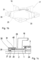
- Figure 1a shows a protective element 30 that can be coupled to a frame corner 28 of a frame 25 of the pan support 17.
- the protective element 30 has a resting part 26 with which it can rest on the thermal protector 1 and a centring part 27 contacting the perimeter 20 of the thermal protector 1, as it is shown in the following.
- the resting part 26 has a hole through which the permanent magnet 40 is inserted, which can contact magnetically the ferromagnetic material 50 of the thermal protector 1.
- Figure 1b shows a pan support 17 with a square frame 25 that has four fingers 16 fixed to this protruding into the frame 25 and creating a resting surface for cooking vessels such as pots or pans and receptacles for food to be cooked.
- Protective elements 30 from figure 1a are mounted on the frame corners 28.
- Figure 1c shows a cross-section view of a zone around a gas burner 3 in a gas cooktop 10.
- the section extends e.g. along the frame corners 28 of the pan support 17.
- the cooktop plate 2 is manufactured as an example from tempered glass or glass ceramics and has an opening 24 for the gas burner 3.
- the thermal protector 1 made like a flat disk is arranged around the area of the gas burner 3.
- the pan support 17, like the one from figure 1b comprises a frame 25 of pan support to which the fingers 16 are fixed protruding into the pan support 17, which create a resting surface for the vessel for food to be cooked (not represented).
- the protective element 30 from figures 1a and 1b is connected to the frame corner 28.
- the protective element 30 has a resting part 26 in which the housing 31 is.
- the permanent magnet 40 is inserted into the housing 31, said permanent magnet 40 resting and being magnetically connected with the ferromagnetic material or the ferromagnetic piece 50 the thermal protector 1 can have.
- the protective element 30 also has a centring part 27 surrounding the frame corner 28 and contacting the perimeter 20 of the thermal protector 1. Since the protective element 30 is made of an elastically deformable material, it can be easily mounted and demounted from the frame 25 and absorbs hits and vibrations that there could be between the frame 25 and the thermal protector 1 and/or with the plate 2. By means of this geometry by a positive connection and permanent magnet 40 of the protective element 30 and of the thermal protector 1, a reliable seat and a fixation of the pan support 17, the thermal protector 1 and the cooktop plate 2 are possible.
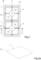
- FIG. 2 shows a gas cooktop 10 of a second embodiment of the invention in a plan view.
- Two burners 3 are provided on a cooktop plate 2 in the representation from figure 2 .
- a square thermal protector 1, represented by a dotted line, is provided in each case around the zones of the gas burners 3.
- the protective elements 30 could be arranged between the corners of the thermal protectors 1.
- the real square outline of the respective thermal protector 1 is covered by the pan support 17 placed above the same resting with its frame 25 against the protective elements 30.
- the pan supports 17 comprise each fingers 16 fixed to the frame 25 of the pan support 17 that protrude inwards, thereby creating a resting surface for cooking vessels such as pots or pans and receptacles for food to be cooked. Since the shape of the frames 25 of pan support and of the square thermal protectors 1 are adapted to each other, the pan supports 17 are placed in such a manner that they do not slide and do not twist on the thermal protectors 1. Therefore, orientation pins or elements can be advantageously avoided. Besides, pan supports 17 extending over both gas burners 3 can be used.
- Figure 2a shows perspectively a square thermal protector 1 having at its corners protective elements 30 inserted into respective orifices 12 of the thermal protector 1.
- Figure 2b shows the same thermal protector 1 from figure 2a but from the bottom showing the protective elements 30 inserted at the corners of the thermal protector 1 and where the housing 31 for the permanent magnet 40 can be seen.
- a pan support 17 with its frame 25 and its fingers 16 for supporting the cooking vessel is shown resting on the thermal protector 1.
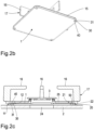
- Figure 2c shows a cross-section view of an area around a gas burner 3 in a gas cooktop 10.
- the section extends along line A-A from figure 2 .
- the cooktop plate 2 manufactured for example from tempered glass or glass ceramics can be observed, comprising an opening 24 for the gas burner 3.
- the thermal protector 1 like the one from figures 2a and 2b is placed, made of metal sheet polished and folded at its perimeter 20 forming a spacer 11 with which it rests on the top surface of the plate 2 and leaves an intermediate space between the thermal protector 1 and the plate 2.
- Near the perimeter 20 of the thermal protector 1 there are orifices 12 into which protective elements 30 are inserted.
- the protective elements 30 are made of an elastically deformable material so they can be inserted into the orifice 12 from the side of the intermediate space and have a housing 31 into which a permanent magnet 40 closer to the orifice 12 is inserted.
- the pan support 17 comprises a frame 25 of pan support to which the fingers 16 are fixed protruding into the pan support 17, which create a resting surface for the vessel for food to be cooked (not represented).
- the frame 25 of pan support has a stepped cross- section with a centring segment 22 surrounding the perimeter 20 of the thermal protector 1 and a resting segment 21 that is placed on the thermal protector 1 resting on the protective elements 30.
- the permanent magnet 40 attracts the ferromagnetic material of the frame 25 or, as it is shown in the right side of the figure, it attracts the ferromagnetic piece 50 embedded into the frame 25.
- FIG 3 shows a plan view of a gas cooktop 10 with thermal protectors 1 and an exemplary configuration of a multiple pan support.
- the gas cooktop 10 also comprises a cooktop plate 2, for example of tempered glass of glass ceramics, four gas burners 3, operating elements 14 and corresponding pan supports 17.
- the rectangular outlines of the thermal protectors 1, which are covered by the pan supports 17 in the plan view can be observed drawn by a dotted line.
- the pan supports 17 represented in figure 3 in the right side correspond to the embodiments of the pan supports 17 schematically shown in figure 2 .
- the left pan support 17 covers both left thermal protectors 1.
- This type of pan support 17 is also designated as a multiple pan support. It is also possible to configure flat pan supports with corresponding frames extending over several of the thermal protectors.
- the variants shown of the gas cooktop and in particular of the thermal protector give a possibility for the protection of heat-sensitive surface areas of cooktop plates against an overheating, which can be realized in an easy manner.
- the thermal protector is made flat in the form of a disk.
- the thermal protector is provided for example with a smooth polished surface, so that it can be easily cleaned.
- the size or surface of the thermal protector can be adapted to the respective installation conditions, the properties of the material of the cooktop plate and the potentially maximum power of the gas burner.
Landscapes
- Engineering & Computer Science (AREA)
- Chemical & Material Sciences (AREA)
- Combustion & Propulsion (AREA)
- Mechanical Engineering (AREA)
- General Engineering & Computer Science (AREA)
- Cookers (AREA)
Claims (10)
- Gaskochstelle (10) mit einer Herdplatte (2), die gehärtetes Glas oder Glaskeramik umfasst, wobei auf der Herdplatte (2) zumindest ein Gasbrenner (3) mit einer Wärmeschutzvorrichtung (1) in Form einer um den Brenner (3) herum verlaufenden flachen Scheibe für den Wärmeschutz der Platte (2) und mit einem Topfträger (17) angeordnet ist, der einen Rahmen (25) umfasst, welcher durch eine formschlüssige Verbindung an zumindest einem Teil des Umfangs (20) der Wärmeschutzvorrichtung (1) angebracht werden kann, dadurch gekennzeichnet, dass er zumindest ein Schutzelement (30) aus einem elastisch verformbaren Material aufweist, das sich mit dem Rahmen (25) oder der Wärmeschutzvorrichtung (1) verbinden lässt, wobei das Schutzelement (30) ein Gehäuse (31) aufweist, das einen Permanentmagneten (40), der magnetisch mit Ferromagnetikum (50) der Wärmeschutzvorrichtung (1) beziehungsweise des Rahmens (25) verbunden sein kann, zumindest teilweise umgibt.
- Gaskochstelle (10) nach Anspruch 1, dadurch gekennzeichnet, dass das Schutzelement (30) auf abnehmbare Weise mit dem Rahmen (25) oder der Wärmeschutzvorrichtung (1) verbunden sein kann.
- Gaskochstelle (10) nach Anspruch 1, dadurch gekennzeichnet, dass es sich bei dem Umfang (20) der Wärmeschutzvorrichtung (1) um einen vieleckigen, vorzugsweise rechteckigen, Umfang handelt.
- Gaskochstelle (10) nach einem der vorhergehenden Ansprüche, dadurch gekennzeichnet, dass die Wärmeschutzvorrichtung (1) als Blech mit einer glatten, glänzenden Oberfläche hergestellt ist, die parallel zur Platte (2) angeordnet ist und mindestens ein Distanzstück (11) aufweist, das die Platte (2) berührt.
- Gaskochstelle (10) nach einem der vorhergehenden Ansprüche, dadurch gekennzeichnet, dass die Wärmeschutzvorrichtung (1) mindestens eine Öffnung (12) aufweist, über die das Schutzelement (30) durch eine formschlüssige Verbindung verbunden werden kann.
- Gaskochstelle (10) nach Anspruch 5, dadurch gekennzeichnet, dass der Rahmen (25) den Gasbrenner (3) umgibt, ein Auflageelement (21), das auf dem Schutzelement (30) aufliegen und mit dem Permanentmagneten (40) magnetisch verbunden sein kann, und ein Zentriersegment (22) aufweist, das das Verschieben auf der Ebene der Platte (2) einschränkt, wenn es die Wärmeschutzvorrichtung (1) oder das Schutzelement (30) berührt.
- Gaskochstelle (10) nach Anspruch 6, dadurch gekennzeichnet, dass der Rahmen (25) aus einem Nichtferromagnetikum hergestellt ist und das Auflagesegment (21) ein ferromagnetisches Teil (50), vorzugsweise einen zweiten Permanentmagneten, aufweist, das mit dem Permanentmagneten (40) magnetisch verbunden sein kann.
- Gaskochstelle (10) nach einem der Ansprüche 1 bis 4, dadurch gekennzeichnet, dass das Schutzelement (30) mit dem Rahmen (25) gekoppelt sein kann und einen Auflageteil (26), der auf der Wärmeschutzvorrichtung (1) aufliegen kann und in dem der Permanentmagnet (40) angeordnet ist, und einen Zentrierteil (27) aufweist, der das Verschieben auf der Fläche der Platte (2) einschränken kann, wenn er in Montageposition des Topfträgers (17) auf der Wärmeschutzvorrichtung (1) die Wärmeschutzvorrichtung (1) berührt.
- Gaskochstelle (10) nach Anspruch 8 bei Abhängigkeit von Anspruch 2, dadurch gekennzeichnet, dass der Rahmen (25) eine Rahmenecke (28) aufweist, die zumindest einen Eckpunkt der Wärmeschutzvorrichtung (1) umgeben kann, und das Schutzelement (30) mit der Rahmenecke (28) gekoppelt ist.
- Gaskochstelle (10) nach einem der vorhergehenden Ansprüche, dadurch gekennzeichnet, dass mehrere Gasbrenner (3) vorgesehen sind, von denen jeder eine Wärmeschutzvorrichtung (1) aufweist, und auf den benachbarten Wärmeschutzvorrichtungen (1, 4) ein Mehrfachtopfträger (17) angeordnet sein kann.
Applications Claiming Priority (2)
| Application Number | Priority Date | Filing Date | Title |
|---|---|---|---|
| EP20382082 | 2020-02-07 | ||
| PCT/EP2021/051284 WO2021156067A1 (en) | 2020-02-07 | 2021-01-21 | Gas cooktop with a thermal protector |
Publications (2)
| Publication Number | Publication Date |
|---|---|
| EP4100682A1 EP4100682A1 (de) | 2022-12-14 |
| EP4100682B1 true EP4100682B1 (de) | 2024-03-13 |
Family
ID=69770805
Family Applications (1)
| Application Number | Title | Priority Date | Filing Date |
|---|---|---|---|
| EP21700956.2A Active EP4100682B1 (de) | 2020-02-07 | 2021-01-21 | Gaskochfeld mit einem thermischen schutz |
Country Status (3)
| Country | Link |
|---|---|
| EP (1) | EP4100682B1 (de) |
| CN (1) | CN115003961A (de) |
| WO (1) | WO2021156067A1 (de) |
Family Cites Families (8)
| Publication number | Priority date | Publication date | Assignee | Title |
|---|---|---|---|---|
| ES2160018B1 (es) | 1998-08-27 | 2002-05-01 | Bsh Fabricacion Sa | Dispositivo de proteccion de los apoyos de las parrillas de aparatos domesticos. |
| EP1106931A3 (de) * | 1999-11-30 | 2003-09-10 | Gronbach Forschung- und Entwicklungs-GmbH & Co. KG | Topfträger für einen Gaskocher |
| DE19957722A1 (de) * | 1999-11-30 | 2001-05-31 | Bsh Bosch Siemens Hausgeraete | Gaskochgerät |
| DE102005046589A1 (de) | 2005-09-28 | 2007-03-29 | BSH Bosch und Siemens Hausgeräte GmbH | Anordnung eines Topfträgers |
| EP1959201A1 (de) * | 2007-02-13 | 2008-08-20 | Espiral Creativa, SL | Kochplatte, die mit einer Antikippvorrichtung für Kochgeschirr versehen ist |
| DE102010028218A1 (de) | 2010-04-27 | 2011-10-27 | BSH Bosch und Siemens Hausgeräte GmbH | Hitzeschild für ein Gaskochfeld und Gaskochfeld |
| DE102012208571A1 (de) * | 2012-05-22 | 2013-11-28 | BSH Bosch und Siemens Hausgeräte GmbH | Kochfeldanordnung |
| CN110529891A (zh) * | 2019-07-31 | 2019-12-03 | 中山百得厨卫有限公司 | 一种磁吸定位锅架的燃气灶 |
-
2021
- 2021-01-21 EP EP21700956.2A patent/EP4100682B1/de active Active
- 2021-01-21 CN CN202180013168.4A patent/CN115003961A/zh active Pending
- 2021-01-21 WO PCT/EP2021/051284 patent/WO2021156067A1/en unknown
Also Published As
| Publication number | Publication date |
|---|---|
| CN115003961A (zh) | 2022-09-02 |
| WO2021156067A1 (en) | 2021-08-12 |
| EP4100682A1 (de) | 2022-12-14 |
Similar Documents
| Publication | Publication Date | Title |
|---|---|---|
| US5571434A (en) | Cooktop stamping having means for attaching heating elements and an integral trim ring | |
| US6410892B1 (en) | Cooktop having a flat glass ceramic cooking surface | |
| JP4820709B2 (ja) | 加熱調理器 | |
| US4491722A (en) | Mounting arrangement for an electric hotplate with a support ring surrounding it | |
| EP4100682B1 (de) | Gaskochfeld mit einem thermischen schutz | |
| EP2501997B1 (de) | Kochfeld | |
| JP2011258442A (ja) | 誘導加熱調理器 | |
| CN102859283A (zh) | 用于煤气灶台的热防护机构和煤气灶台 | |
| JP2003045626A (ja) | 窪み湾曲した加熱面を有するガラスセラミックボウルを備えた調理台 | |
| KR101916810B1 (ko) | 언더 레인지용 불판 | |
| EP0985887B1 (de) | Sicherheitseinrichtungen an Kochstellenoberteilen | |
| JP4869025B2 (ja) | 加熱調理器 | |
| CN217464546U (zh) | 电磁烹饪器具和电磁烹饪套组 | |
| KR100348841B1 (ko) | 시스템 키친의 조리 렌지용 상판 | |
| JP3891264B2 (ja) | ガスコンロ | |
| WO2022157066A1 (en) | A cooking device with a fixation element | |
| CN217057629U (zh) | 一种面板定位锅架的燃气灶安装结构 | |
| CN211673690U (zh) | 煲体组件和具有该煲体组件的烹饪器具 | |
| CN216020468U (zh) | 一种电压力锅和发热盘的组合电热锅 | |
| CN110748929A (zh) | 灶具 | |
| CN220124446U (zh) | 煲体及具有其的烹饪器具 | |
| CN214370427U (zh) | 烹饪器具 | |
| EP2798276B1 (de) | Kocher | |
| CN216346441U (zh) | 一种嵌入式电磁炉 | |
| JPS6335290Y2 (de) |
Legal Events
| Date | Code | Title | Description |
|---|---|---|---|
| STAA | Information on the status of an ep patent application or granted ep patent |
Free format text: STATUS: UNKNOWN |
|
| STAA | Information on the status of an ep patent application or granted ep patent |
Free format text: STATUS: THE INTERNATIONAL PUBLICATION HAS BEEN MADE |
|
| PUAI | Public reference made under article 153(3) epc to a published international application that has entered the european phase |
Free format text: ORIGINAL CODE: 0009012 |
|
| STAA | Information on the status of an ep patent application or granted ep patent |
Free format text: STATUS: REQUEST FOR EXAMINATION WAS MADE |
|
| 17P | Request for examination filed |
Effective date: 20220907 |
|
| AK | Designated contracting states |
Kind code of ref document: A1 Designated state(s): AL AT BE BG CH CY CZ DE DK EE ES FI FR GB GR HR HU IE IS IT LI LT LU LV MC MK MT NL NO PL PT RO RS SE SI SK SM TR |
|
| DAV | Request for validation of the european patent (deleted) | ||
| DAX | Request for extension of the european patent (deleted) | ||
| GRAP | Despatch of communication of intention to grant a patent |
Free format text: ORIGINAL CODE: EPIDOSNIGR1 |
|
| STAA | Information on the status of an ep patent application or granted ep patent |
Free format text: STATUS: GRANT OF PATENT IS INTENDED |
|
| INTG | Intention to grant announced |
Effective date: 20231024 |
|
| GRAS | Grant fee paid |
Free format text: ORIGINAL CODE: EPIDOSNIGR3 |
|
| GRAA | (expected) grant |
Free format text: ORIGINAL CODE: 0009210 |
|
| STAA | Information on the status of an ep patent application or granted ep patent |
Free format text: STATUS: THE PATENT HAS BEEN GRANTED |
|
| AK | Designated contracting states |
Kind code of ref document: B1 Designated state(s): AL AT BE BG CH CY CZ DE DK EE ES FI FR GB GR HR HU IE IS IT LI LT LU LV MC MK MT NL NO PL PT RO RS SE SI SK SM TR |
|
| REG | Reference to a national code |
Ref country code: GB Ref legal event code: FG4D |
|
| REG | Reference to a national code |
Ref country code: CH Ref legal event code: EP |
|
| REG | Reference to a national code |
Ref country code: DE Ref legal event code: R096 Ref document number: 602021010385 Country of ref document: DE |
|
| REG | Reference to a national code |
Ref country code: IE Ref legal event code: FG4D |