EP4100620B1 - Systèmes et procédés de surveillance de torche en mer en temps réel dans des navires de forage - Google Patents
Systèmes et procédés de surveillance de torche en mer en temps réel dans des navires de forage Download PDFInfo
- Publication number
- EP4100620B1 EP4100620B1 EP21708902.8A EP21708902A EP4100620B1 EP 4100620 B1 EP4100620 B1 EP 4100620B1 EP 21708902 A EP21708902 A EP 21708902A EP 4100620 B1 EP4100620 B1 EP 4100620B1
- Authority
- EP
- European Patent Office
- Prior art keywords
- data
- communication device
- temperature detector
- temperature
- flaring
- Prior art date
- Legal status (The legal status is an assumption and is not a legal conclusion. Google has not performed a legal analysis and makes no representation as to the accuracy of the status listed.)
- Active
Links
Images


Classifications
-
- E—FIXED CONSTRUCTIONS
- E21—EARTH OR ROCK DRILLING; MINING
- E21B—EARTH OR ROCK DRILLING; OBTAINING OIL, GAS, WATER, SOLUBLE OR MELTABLE MATERIALS OR A SLURRY OF MINERALS FROM WELLS
- E21B41/00—Equipment or details not covered by groups E21B15/00 - E21B40/00
- E21B41/005—Waste disposal systems
- E21B41/0071—Adaptation of flares, e.g. arrangements of flares in offshore installations
-
- G—PHYSICS
- G01—MEASURING; TESTING
- G01K—MEASURING TEMPERATURE; MEASURING QUANTITY OF HEAT; THERMALLY-SENSITIVE ELEMENTS NOT OTHERWISE PROVIDED FOR
- G01K1/00—Details of thermometers not specially adapted for particular types of thermometer
- G01K1/02—Means for indicating or recording specially adapted for thermometers
- G01K1/024—Means for indicating or recording specially adapted for thermometers for remote indication
-
- E—FIXED CONSTRUCTIONS
- E21—EARTH OR ROCK DRILLING; MINING
- E21B—EARTH OR ROCK DRILLING; OBTAINING OIL, GAS, WATER, SOLUBLE OR MELTABLE MATERIALS OR A SLURRY OF MINERALS FROM WELLS
- E21B41/00—Equipment or details not covered by groups E21B15/00 - E21B40/00
-
- G—PHYSICS
- G08—SIGNALLING
- G08B—SIGNALLING SYSTEMS, e.g. PERSONAL CALLING SYSTEMS; ORDER TELEGRAPHS; ALARM SYSTEMS
- G08B21/00—Alarms responsive to a single specified undesired or abnormal condition and not otherwise provided for
- G08B21/18—Status alarms
- G08B21/182—Level alarms, e.g. alarms responsive to variables exceeding a threshold
-
- G—PHYSICS
- G08—SIGNALLING
- G08B—SIGNALLING SYSTEMS, e.g. PERSONAL CALLING SYSTEMS; ORDER TELEGRAPHS; ALARM SYSTEMS
- G08B25/00—Alarm systems in which the location of the alarm condition is signalled to a central station, e.g. fire or police telegraphic systems
- G08B25/01—Alarm systems in which the location of the alarm condition is signalled to a central station, e.g. fire or police telegraphic systems characterised by the transmission medium
- G08B25/10—Alarm systems in which the location of the alarm condition is signalled to a central station, e.g. fire or police telegraphic systems characterised by the transmission medium using wireless transmission systems
-
- G—PHYSICS
- G01—MEASURING; TESTING
- G01S—RADIO DIRECTION-FINDING; RADIO NAVIGATION; DETERMINING DISTANCE OR VELOCITY BY USE OF RADIO WAVES; LOCATING OR PRESENCE-DETECTING BY USE OF THE REFLECTION OR RERADIATION OF RADIO WAVES; ANALOGOUS ARRANGEMENTS USING OTHER WAVES
- G01S19/00—Satellite radio beacon positioning systems; Determining position, velocity or attitude using signals transmitted by such systems
- G01S19/01—Satellite radio beacon positioning systems transmitting time-stamped messages, e.g. GPS [Global Positioning System], GLONASS [Global Orbiting Navigation Satellite System] or GALILEO
- G01S19/13—Receivers
Definitions
- Embodiments of the present disclosure relate to systems and methods for real-time offshore flare monitoring in drilling ships.
- Drill ships are special purpose ships which are used for drilling on the ocean beds at deep seas. Such offshore drilling ships, relative to their operational peers have come to be regarded as a safe and sure option for extracting oil and gas at the sea.
- a drill ship is usually a merchant vessel designed for use in exploratory offshore drilling of new oil and gas wells or for scientific drilling purposes. In most recent years the vessels have been used in deep water and ultra-deep water applications.
- Drill ships must stay relatively stationary on location in the water for extended periods of time. This positioning may be accomplished with multiple anchors, dynamic propulsion (thrusters), or a combination of these. Drill ships typically carry larger payloads than semisubmersible drilling vessels, but their motion characteristics are usually inferior. The drill ship can also be used as a platform to carry out well maintenance or completion work such as casing and tubing installation, subsea tree installations, and well capping.
- Flaring is a process by which excess fluids (gases and in some circumstances liquids) are released and combusted at a flare stack. These excess fluids are derived from multiple sources within commercial and industrial processing facilities, for example, petroleum refineries. Flare sources can be based on process control design in which flaring events are routine and anticipated, and occur for equipment and personal safety. Flare sources can also result from unplanned events such as operational upsets, plant emergencies, equipment failures, plant start-ups, plant shut-downs, inspection activities, human errors and the like. There is considerable motivation to reduce losses in petroleum refinery operations; particularly losses associated with flaring.
- flare monitoring systems typically monitor flare conditions via a flowmeter located at the flare. This configuration makes it difficult to determine the source of non-routine flare events, which often have significant impact on plant operations.
- TMFMs thermal mass flow meters
- TMFMs operate under the constant temperature differential method and provide a direct mass flow rate without the need for temperature or pressure compensation.
- the discussed TMFMs include remote process monitoring functions that allow a user to adjust meter configuration, evaluate transmitter alarm conditions, collect process data, and view measurements from a PC or control station.
- one example embodiment is a device for monitoring flaring activities on a drill ship according to claim 1 .
- the device includes a resistive temperature detector configured to determine a temperature within a sensing area of the resistive temperature detector, and a communication device operably connected to the resistive temperature detector, wherein the communication device is configured to receive the temperature data from the resistive temperature detector and send the temperature data to a remote system.
- the device may also include a global positioning system operably connected to the communication device, the global positioning system configured to identify a location of the drill ship in real-time and send the location data to the communication device, wherein the communication device is configured to send the location data to the remote system.
- the communication device may include a microcontroller and transceiver unit configured to transmit data gathered by the communication device, wherein the resistive temperature detector is operatively coupled to the microcontroller.
- the device may also include a power storage unit configured to provide power to the resistive temperature detector, the communication device, and the global position system.
- the microcontroller may be further configured to generate an alarm if the temperature determined by the resistive temperature detector exceeds a predetermined value.
- the remote system may include a receiver configured to receive data transmitted by the communication device, one or more processors operably connected to the receiver, and a non-transitory computer readable medium in communication with the one or more processors, the computer readable medium configured to store the temperature data, the location data, and the time data associated with the respective temperature data and location data.
- the remote system may also include a display device configured to display the temperature data, the location data, and the time data associated with the respective temperature data and location data.
- the transceiver unit in the communication device may be configured to communicate over a wireless communication method selected from the group consisting of Wi-Fi, Wi-Fi Direct, Bluetooth, Bluetooth Low Energy, ZigBee, 3G, 4G, 4G LTE, 5G, and a cellular network.
- the system may include a plurality of devices in wireless communication with each other on the drill ship, each of the devices including a resistive temperature detector configured to determine a temperature within a sensing area of the resistive temperature detector, and a communication device operably connected to the resistive temperature detector, wherein the communication device is configured to receive the temperature data from the resistive temperature detector and send the temperature data to a remote system.
- the device may also include a global positioning system operably connected to the communication device, the global positioning system configured to identify a location of the drill ship in real-time and send the location data to the communication device, wherein the communication device is configured to send the location data to the remote system.
- the remote system may also include a receiver configured to receive data transmitted by the communication device, one or more processors operably connected to the receiver, and a non-transitory computer readable medium in communication with the one or more processors, the computer readable medium configured to store the temperature data, the location data, and the time data associated with the respective temperature data and location data.
- the remote system may also include a display device configured to display the temperature data, the location data, and the time data associated with the respective temperature data and location data.
- the method may include providing a plurality of devices in wireless communication with each other on the drill ship, each of the devices including a resistive temperature detector configured to determine a temperature within a sensing area of the resistive temperature detector, and a communication device operably connected to the resistive temperature detector, wherein the communication device is configured to receive the temperature data from the resistive temperature detector and send the temperature data to a remote system.
- the devices may also include a global positioning system operably connected to the communication device, the global positioning system configured to identify a location of the drill ship in real-time and send the location data to the communication device, wherein the communication device is configured to send the location data to the remote system.
- the method may also include receiving, by the remote system, data transmitted by the communication device, and storing the temperature data, the location data, and the time data associated with the respective temperature data and location data in a computer readable medium.
- the method may further include displaying, on the remote system, the temperature data, the location data, and the time data associated with the respective temperature data and location data.
- the method may also include generating an alarm, by the remote system, if the temperature determined by the resistive temperature detector exceeds a predetermined value.
- the system may include a resistive temperature detector (RTD), which can be installed within the vicinity of a flaring boom or within an appropriate distance to detect the flaring heat.
- RTD resistive temperature detector
- the system may also include telemetry system to automate the communication process and to enable the data to be transmitted to a receiving device for real-time monitoring purposes.
- the system may also include a global positioning system (GPS) to link the flaring activities with the location of ship and to enable obtaining auditable information when needed.
- GPS global positioning system
- the system may also include a database to receive the streaming data and archive it.
- the system may also have atmospheric and hydrodynamic modeling capabilities where environmental models may be used to backtrack the source of the spill or smoke by utilizing state of the art technologies.
- the system can be customized to generate an alarm when the air temperature exceeds, for example, 75 °C within the RTD vicinity. Therefore, any temperature deviations from the average air temperature will be recorded and the alarm will be set off through the organization system and archived. If an oil spill or unknown source of smoke is detected, the organization can get back to check their record of the flaring activities and link the incident properly with the GPS coordinates. Modeling can also be utilized to backtrack the source of the spill.
- Fig. 1 illustrates a system 100 for monitoring flaring activities 120 on a drill ship 150.
- the system 100 may include a plurality of devices 110 in wireless communication with each other on the drill ship 150.
- the system 100 may also include a remote system 130 which may be in wireless communication with each of the devices 110 on the drill ship 150.
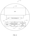
- Fig. 2 illustrates a schematic view of the device 110 shown in Fig. 1 .
- Each of the devices 110 including a temperature sensor 102, such as a resistive temperature detector (RTD) configured to determine a temperature within a sensing area of the resistive temperature detector.
- the device 110 also includes a communication device 104 operably connected to the resistive temperature detector 102.
- the communication device 104 may be configured to receive the temperature data from the resistive temperature detector 102 and send the temperature data to a remote system 130, as shown in Fig. 1 for example.
- the device 110 may also include a global positioning system (GPS) 106 operably connected to the communication device 104.
- GPS global positioning system
- the global positioning system 106 may be configured to identify a location of the drill ship 150 in real-time and send the location data to the communication device 104.
- the communication device 104 may be configured to send the location data to the remote system 130.
- the communication device 104 may include a microcontroller or microprocessor unit 112 and a transceiver unit 114 configured to transmit data gathered by the communication device 104 using one or more antennas.
- the resistive temperature detector 102 may be operatively coupled to the microcontroller 112.
- the device 110 may also include a power storage unit 108 configured to provide power to the resistive temperature detector 102, the communication device 104, and the global position system 106.
- the microcontroller unit 112 may be further configured to generate an alarm if the temperature determined by the resistive temperature detector 102 exceeds a predetermined value, for example 75 degrees Celsius.
- the transceiver unit 114 in the communication device 104 may be configured to communicate over a wireless communication method selected from the group consisting of Wi-Fi, Wi-Fi Direct, Bluetooth, Bluetooth Low Energy, ZigBee, 3G, 4G, 4G LTE, 5G, and a cellular network.
- the remote system 130 may also include a receiver configured to receive data transmitted by the communication device 104.
- the remote system 130 may also include one or more processors operably connected to the receiver, and a non-transitory computer readable medium in communication with the one or more processors.
- the computer readable medium may be configured to store the temperature data, the location data, and the time data associated with the respective temperature data and location data.
- the remote system 130 which will be described with reference to Fig. 3 in sections below, may also include a display device configured to display the temperature data, the location data, and the time data associated with the respective temperature data and location data.
- the method may include providing a plurality of devices in wireless communication with each other on the drill ship, each of the devices including a resistive temperature detector configured to determine a temperature within a sensing area of the resistive temperature detector, and a communication device operably connected to the resistive temperature detector, wherein the communication device is configured to receive the temperature data from the resistive temperature detector and send the temperature data to a remote system.
- the devices may also include a global positioning system operably connected to the communication device, the global positioning system configured to identify a location of the drill ship in real-time and send the location data to the communication device, wherein the communication device is configured to send the location data to the remote system.
- the method may also include receiving, by the remote system, data transmitted by the communication device, and storing the temperature data, the location data, and the time data associated with the respective temperature data and location data in a computer readable medium.
- the method may further include displaying, on the remote system, the temperature data, the location data, and the time data associated with the respective temperature data and location data.
- the method may also include generating an alarm, by the remote system, if the temperature determined by the resistive temperature detector exceeds a predetermined value.
- a flare monitoring system can be run using known software or other suitable real-time data infrastructure and collaboration tool.
- the entire facility flare system is thus ascertained showing the location of each flare-through element (e.g., control valve, manual valve, restricting orifice, etc.), for all equipment that contribute to both the low pressure, high pressure or acid flare headers from each plant within the facility.
- each flare-through element e.g., control valve, manual valve, restricting orifice, etc.
- the information can be imported in OSIsoft, LLC's ProcessBook or other suitable real-time data infrastructure and collaboration tool, whereby the Cv Percent Opening can be displayed, e.g., as a horizontal bar graph, and the FV Tag data can be displayed as a numeric value.
- Reports can be generated based on the overall network, an individual plant, a selected group of plants within a refinery, or a portion of a plant.
- the data presented at this level can include, for instance, a chart that presents daily flaring activity for a given refinery in volume, with correlated equivalent in terms of barrels of crude per day, and monetary equivalents. This can be presented as data tables and/or graphs.
- the data reports can be provided, separately or in conjunction with the above, based on a given source in each plant.
- the data reports can be provided, separately or in conjunction with the above, based on all of the plants in a given refinery to demonstrate the plant(s) responsible for a majority of flaring events.
- the reports of flare data can incorporate certain assumptions including the average heat content of crude oil, the average heat of combustion for pure gases at standard conditions, and the gas monetary value.
- Flare sources can be based on process control design in which flaring events are classified as routine or non-routine. Routine flare sources are anticipated and occur for equipment and personal safety, and include, for instance, purging gas to eliminate air from the flare headers, leakage, and normal operation of control valve discharges based on process design considerations.
- Non-routine flaring events include those resulting from unplanned events such as operational upsets that increase the volume of flare gas produced or decrease the ability of the gas handling system to accommodate it, such as pressure relieve malfunction, equipment overpressure or other cause for relieving relief valves, equipment plugging resulting in local overpressure, loss of a major process unit compressor (e.g., FCC wet gas compressor), loss of fuel gas recovery system compressors, reciprocating compressor seats overheating from high nitrogen or hydrogen content, fuel gas with low specific gravity or high heat of compression resulting in overheating, high inlet temperature to the flare gas compressor, and/or general mechanical problems from the operation of rotating equipment.
- a major process unit compressor e.g., FCC wet gas compressor
- loss of fuel gas recovery system compressors e.g., reciprocating compressor seats overheating from high nitrogen or hydrogen content
- fuel gas with low specific gravity or high heat of compression resulting in overheating, high inlet temperature to the flare gas compressor, and/or general mechanical problems from the operation of rotating equipment.
- Non-routine flaring events are also a result of plant emergencies (equipment failures and operational errors that result in equipment overpressure, typically leading to relief valves opening to the flare system, which can be classified as emergencies; emergency flaring events are severe instances of upsets or malfunction and often have the same set of basic causes); mechanical failure (flaring attributed to mechanical equipment or instrumentation failure); startup and shutdown (flaring attributed to startup and shutdown); process/fuel imbalance (flaring resulting from temporary fuel imbalance in the fuel system or inadequate gas processing capacity); and other causes (including instances of flaring not attributable to the above categories such as specific actions by operation staff or any other operational situations to be specified by the facilities).
- classification into one of the above categories or subcategories should be accomplished along with identification of the source, the rate, duration and the reasons of flaring, repetitive flaring from the same plant/equipment along with the corrective actions to be undertaken to avoid recurrence of such events in future need to specified.
- Computer system 130 includes a processor 202, such as a central processing unit, an input/output interface 204 and support circuitry 206.
- a display 208 and an input device 210 such as a keyboard, mouse or pointer are also provided.
- the display 208, input device 210, processor 202, and support circuitry 206 are shown connected to a bus 212 which also connects to a memory 214.
- Memory 214 includes program storage memory 216 and data storage memory 218.
- computer 130 is depicted with direct human interface components display 208 and input device 210, programming of modules and exportation of data can alternatively be accomplished over the interface 204, for instance, where the computer 130 is connected to a network and the programming and display operations occur on another associated computer, or via a detachable input device as is known with respect to interfacing programmable logic controllers.
- Program storage memory 216 and data storage memory 218 can each comprise volatile (RAM) and non-volatile (ROM) memory units and can also comprise hard disk and backup storage capacity, and both program storage memory 216 and data storage memory 218 can be embodied in a single memory device or separated in plural memory devices.
- Program storage memory 216 stores software program modules and associated data, and in particular stores one or more of the data historian module 220, computation module 230 and display module 240, or a combination including at least one of the foregoing modules.
- Data storage memory 218 stores tags and other data generated by the one or more modules of the present invention and event data received by the flare-through elements.
- the computing device 130 preferably supports an operating system, for example stored in program storage memory 216 and executed by the processor 202 from volatile memory.
- the computer system 130 can be any computer such as a personal computer, minicomputer, workstation, mainframe, a dedicated controller such as a programmable logic controller, or a combination thereof. While the computer system 130 is shown, for illustration purposes, as a single computer unit, the system can comprise a group/farm of computers which can be scaled depending on the processing load and database size.
Landscapes
- Engineering & Computer Science (AREA)
- Physics & Mathematics (AREA)
- Mining & Mineral Resources (AREA)
- Geology (AREA)
- Life Sciences & Earth Sciences (AREA)
- General Physics & Mathematics (AREA)
- Environmental & Geological Engineering (AREA)
- Emergency Management (AREA)
- Business, Economics & Management (AREA)
- Fluid Mechanics (AREA)
- General Life Sciences & Earth Sciences (AREA)
- Geochemistry & Mineralogy (AREA)
- Computer Networks & Wireless Communication (AREA)
- Arrangements For Transmission Of Measured Signals (AREA)
Claims (15)
- Dispositif pour surveiller des activités de torchage (120) sur un navire de forage (150), le dispositif comprenant :un thermomètre à résistance (102) localisé sur le navire de forage et configuré pour déterminer une température au sein d'une zone de détection du thermomètre à résistance, le thermomètre à résistance étant installé à une distance d'une torchère où une chaleur de torchage d'une activité de torchage est détectée, et configuré pour déterminer une température au sein d'une zone de détection du thermomètre à résistance ; etun dispositif de communication (104) connecté de manière opérationnelle au thermomètre à résistance, dans lequel le dispositif de communication est configuré pour recevoir les données de température en provenance du thermomètre à résistance et pour envoyer les données de température à un système de surveillance de torche (100) qui est opérationnel pour enregistrer une heure de début, une durée et une heure de fin de l'activité de torchage.
- Dispositif selon la revendication 1, comprenant en outre :un système de positionnement mondial (106) connecté de manière opérationnelle au dispositif de communication (104), le système de positionnement mondial étant configuré pour identifier une localisation du navire de forage (150) en temps réel et envoyer les données de localisation au dispositif de communication, dans lequel le dispositif de communication est configuré pour envoyer les données de localisation au système distant (130) ;un microcontrôleur (112) et une unité d'émission-réception (114) configurés pour transmettre des données rassemblées par le dispositif de communication, dans lequel le thermomètre à résistance (102) est couplé de manière opérationnelle au microcontrôleur et dans lequel le microcontrôleur est en outre configuré pour générer une alarme si la température déterminée par le thermomètre à résistance dépasse une valeur prédéterminée ;un dispositif d'affichage configuré pour afficher les données de température, les données de localisation et les données de temps associées aux données de température et aux données de localisation respectives ; etune unité de stockage d'énergie (108) configurée pour fournir de l'énergie au thermomètre à résistance, au dispositif de communication et au système de positionnement mondial.
- Dispositif selon la revendication 2, dans lequel le système distant (130) comprend en outre :un récepteur configuré pour recevoir des données transmises par le dispositif de communication (104) ;un ou plusieurs processeurs (202) connectés de manière opérationnelle au récepteur ; etun support non transitoire lisible sur ordinateur en communication avec les un ou plusieurs processeurs, le support lisible sur ordinateur étant configuré pour stocker les données de température, les données de localisation et les données de temps associées aux données de température et aux données de localisation respectives.
- Dispositif selon la revendication 2, dans lequel l'unité d'émission-réception (114) est configurée pour communiquer par un procédé de communication sans fil sélectionné dans le groupe constitué par le Wi-Fi, le Wi-Fi Direct, le Bluetooth, le Bluetooth Low Energy, ZigBee, la 3G, la 4G, la 4G LTE, la 5G et un réseau cellulaire.
- Système pour surveiller des activités de torchage (120) sur un navire de forage (150), le système comprenant :
une pluralité de dispositifs (110) localisés sur le navire de forage en communication sans fil les uns avec les autres sur le navire de forage, chacun des dispositifs comprenant :un thermomètre à résistance (102) configuré pour déterminer une température au sein d'une zone de détection du thermomètre à résistance, le thermomètre à résistance étant installé à distance d'une torchère où une chaleur de torchage d'une activité de torchage est détectée, et configuré pour déterminer une température au sein d'une zone de détection du thermomètre à résistance ; etun dispositif de communication (104) connecté de manière opérationnelle au thermomètre à résistance, dans lequel le dispositif de communication est configuré pour recevoir les données de température en provenance du thermomètre à résistance et pour envoyer les données de température à un système de surveillance de torche (100) qui est opérationnel pour enregistrer une heure de début, une durée et une heure de fin de l'activité de torchage. - Système selon la revendication 5, chacun des dispositifs (110) comprennent en outre :
un système de positionnement mondial (106) connecté de manière opérationnelle au dispositif de communication (104), le système de positionnement mondial étant configuré pour identifier une localisation du navire de forage (150) en temps réel et envoyer les données de localisation au dispositif de communication, dans lequel le dispositif de communication est configuré pour envoyer les données de localisation au système distant (130). - Système selon la revendication 6, dans lequel le dispositif de communication (104) comprend en outre :un microcontrôleur (112) et une unité d'émission-réception (114) configurées pour transmettre des données rassemblées par le dispositif de communication, dans lequel le thermomètre à résistance (102) est couplé de manière opérationnelle au microcontrôleur, dans lequel le microcontrôleur est configuré pour générer une alarme si la température déterminée par le thermomètre à résistance dépasse une valeur prédéterminée ; etune unité de stockage d'énergie (108) configurée pour fournir de l'énergie au thermomètre à résistance, au dispositif de communication et au système de positionnement mondial (106).
- Système selon la revendication 5, dans lequel le système distant (130) comprend en outre :un récepteur configuré pour recevoir des données transmises par le dispositif de communication (104) ;un ou plusieurs processeurs (202) connectés de manière opérationnelle au récepteur ; etun support non transitoire lisible sur ordinateur en communication avec les un ou plusieurs processeurs, le support lisible sur ordinateur étant configuré pour stocker les données de température, les données de localisation et les données de temps associées aux données de température et aux données de localisation respectives.
- Système selon la revendication 8, dans lequel le système distant (130 comprend en outre :
un dispositif d'affichage configuré pour afficher les données de température, les données de localisation et les données de temps associées aux données de température et aux données de localisation respectives. - Système selon la revendication 7, dans lequel l'unité d'émission-réception (114) est configurée pour communiquer par un procédé de communication sans fil sélectionné dans le groupe constitué par le Wi-Fi, le Wi-Fi Direct, le Bluetooth, le Bluetooth Low Energy, ZigBee, la 3G, la 4G, la 4G LTE, la 5G et un réseau cellulaire.
- Procédé pour surveiller des activités de torchage (120) sur un navire de forage (150), le procédé comprenant :
la fourniture d'une pluralité de dispositifs (110) en communication sans fil les uns avec les autres sur le navire de forage, chacun des dispositifs comprenant :un thermomètre à résistance (102) localisé sur le navire de forage et configuré pour déterminer une température au sein d'une zone de détection du thermomètre à résistance ; etun dispositif de communication (104) connecté de manière opérationnelle au thermomètre à résistance, dans lequel le dispositif de communication est configuré pour recevoir les données de température en provenance du thermomètre à résistance et envoyer les données de température à un système distant ;détecter une chaleur de torchage d'une activité de torchage avec le thermomètre à résistance ; etenregistrer une heure de début, une durée et une heure de fin de l'activité de torchage. - Procédé selon la revendication 11, dans lequel chacun des dispositifs (110) comprennent en outre :
un système de positionnement mondial (106) connecté de manière opérationnelle au dispositif de communication (104), le système de positionnement mondial étant configuré pour identifier une localisation du navire de forage (150) en temps réel et envoyer les données de localisation au dispositif de communication, dans lequel le dispositif de communication est configuré pour envoyer les données de localisation au système distant (130). - Procédé selon l'une quelconque des revendications 11 à 12, comprenant en outre :la réception, par le système distant (130), de données transmises par le dispositif de communication (104) ; etle stockage des données de température, des données de localisation et des données de temps associées aux données de température et aux données de localisation respectives dans un support lisible sur ordinateur.
- Procédé selon l'une quelconque des revendications 11 à 13, comprenant en outre :
l'affichage, sur le système distant (130), des données de température, des données de localisation et des données de temps associées aux données de température et aux données de localisation respectives. - Procédé selon l'une quelconque des revendications 11 à 14, comprenant en outre :
la génération d'une alarme, par le système distant (130), si la température déterminée par le thermomètre à résistance (102) dépasse une valeur prédéterminée.
Applications Claiming Priority (2)
| Application Number | Priority Date | Filing Date | Title |
|---|---|---|---|
| US16/779,835 US11467039B2 (en) | 2020-02-03 | 2020-02-03 | Systems and methods for real-time offshore flare monitoring in drilling ships |
| PCT/US2021/070121 WO2021159145A1 (fr) | 2020-02-03 | 2021-02-03 | Systèmes et procédés de surveillance de torche en mer en temps réel dans des navires de forage |
Publications (2)
| Publication Number | Publication Date |
|---|---|
| EP4100620A1 EP4100620A1 (fr) | 2022-12-14 |
| EP4100620B1 true EP4100620B1 (fr) | 2025-03-26 |
Family
ID=74798122
Family Applications (1)
| Application Number | Title | Priority Date | Filing Date |
|---|---|---|---|
| EP21708902.8A Active EP4100620B1 (fr) | 2020-02-03 | 2021-02-03 | Systèmes et procédés de surveillance de torche en mer en temps réel dans des navires de forage |
Country Status (4)
| Country | Link |
|---|---|
| US (1) | US11467039B2 (fr) |
| EP (1) | EP4100620B1 (fr) |
| SA (1) | SA522433426B1 (fr) |
| WO (1) | WO2021159145A1 (fr) |
Family Cites Families (23)
| Publication number | Priority date | Publication date | Assignee | Title |
|---|---|---|---|---|
| US4839527A (en) | 1986-10-28 | 1989-06-13 | Alan Leitch | Optical-fibre smoke detection/analysis system |
| US4871307A (en) | 1988-11-02 | 1989-10-03 | Harris George W | Flame ignition and monitoring system and method |
| JP3612472B2 (ja) | 2000-06-22 | 2005-01-19 | 株式会社日立製作所 | 遠隔監視診断システム、及び遠隔監視診断方法 |
| EP1637695A1 (fr) | 2000-09-22 | 2006-03-22 | Weatherford/Lamb, Inc. | Méthode et appareil pour la monitorisation et le contrôle à distance. |
| CA2841491C (fr) | 2006-12-18 | 2019-04-16 | Baker Hughes Incorporated | Systeme, produit programme, et procede permettant la visualisation et la prise en compte d'un appareil de forage |
| US7876229B2 (en) | 2007-08-14 | 2011-01-25 | Honeywell International Inc. | Flare monitoring |
| US20090309028A1 (en) | 2008-06-16 | 2009-12-17 | Honeywell International Inc. | Intelligent system and method to monitor object movement |
| US8863734B2 (en) | 2008-12-01 | 2014-10-21 | General Electric Company | Gas grill |
| US8347983B2 (en) * | 2009-07-31 | 2013-01-08 | Weatherford/Lamb, Inc. | Drilling with a high pressure rotating control device |
| US8838390B1 (en) | 2011-02-17 | 2014-09-16 | Selman and Associates, Ltd. | System for gas detection, well data collection, and real time streaming of well logging data |
| US9297251B2 (en) * | 2013-02-20 | 2016-03-29 | Schlumberger Technology Corporation | Drill bit systems with temperature sensors and applications using temperature sensor measurements |
| US9142111B2 (en) | 2013-03-15 | 2015-09-22 | Saudi Arabian Oil Company | Flare network monitorng system and method |
| EP3869361A1 (fr) * | 2013-09-03 | 2021-08-25 | Fugro Chance, Inc. | Système de guidage à distance interactif pour navires maritimes |
| CA3114662A1 (fr) | 2013-10-07 | 2015-04-07 | Strata Products Worldwide, Llc | Appareil de surveillance de gaz, systeme et procede connexes |
| US20150260397A1 (en) | 2014-03-17 | 2015-09-17 | Honeywell International Inc. | Integrated smoke monitoring and control system for flaring operations |
| AU2014224154B8 (en) | 2014-07-09 | 2015-07-02 | Woodside Energy Technologies Pty Ltd | System and method for heading control of a floating lng vessel using a set of real-time monitored cargo containment system strain data |
| US20180283148A1 (en) * | 2015-10-30 | 2018-10-04 | Halliburton Energy Services, Inc. | Automated lift-gas balancing in oil production |
| US10043288B2 (en) * | 2015-11-10 | 2018-08-07 | Honeywell International Inc. | Methods for monitoring combustion process equipment |
| US20170159372A1 (en) * | 2015-12-04 | 2017-06-08 | Schlumberger Technology Corporation | Rig positioning system |
| GB2550868B (en) * | 2016-05-26 | 2019-02-06 | Metrol Tech Ltd | Apparatuses and methods for sensing temperature along a wellbore using temperature sensor modules comprising a crystal oscillator |
| US10850314B2 (en) | 2018-06-04 | 2020-12-01 | Daniel W. Chambers | Remote gas monitoring and flare control system |
| US11493661B2 (en) * | 2018-09-13 | 2022-11-08 | Schlumberger Technology Corporation | Downhole NMR system |
| CN109284709B (zh) | 2018-09-19 | 2021-08-17 | 南京大学 | 一种基于耀光反射差异的海面溢油光学遥感检测方法 |
-
2020
- 2020-02-03 US US16/779,835 patent/US11467039B2/en active Active
-
2021
- 2021-02-03 EP EP21708902.8A patent/EP4100620B1/fr active Active
- 2021-02-03 WO PCT/US2021/070121 patent/WO2021159145A1/fr not_active Ceased
-
2022
- 2022-07-26 SA SA522433426A patent/SA522433426B1/ar unknown
Also Published As
| Publication number | Publication date |
|---|---|
| WO2021159145A1 (fr) | 2021-08-12 |
| EP4100620A1 (fr) | 2022-12-14 |
| US20210239537A1 (en) | 2021-08-05 |
| US11467039B2 (en) | 2022-10-11 |
| SA522433426B1 (ar) | 2024-06-04 |
Similar Documents
| Publication | Publication Date | Title |
|---|---|---|
| Korlapati et al. | Review and analysis of pipeline leak detection methods | |
| US20190019352A1 (en) | Boat monitoring and tracking | |
| US8479566B2 (en) | Pipeline leak detection system | |
| KR101721575B1 (ko) | 다중매체 통신 기반 선박 상태모니터링과 최적 및 안전 운항 지원을 수행하는 선박 운항 지원 시스템 및 그 방법 | |
| US20150072319A1 (en) | System and method for integrated marine and process simulation | |
| US9845664B2 (en) | System and method for communicating with a drill rig | |
| CN102778245A (zh) | 海底传感器显示系统和方法 | |
| US11977399B2 (en) | Fluid pressure monitoring system using flow data | |
| EP4100620B1 (fr) | Systèmes et procédés de surveillance de torche en mer en temps réel dans des navires de forage | |
| US20220138031A1 (en) | Auto-hypotheses iteration to converge into situation-specific scientific causation using intuition technology framework | |
| EP2584420A1 (fr) | Surveillance des turbulences d'un pipeline sous-marin | |
| AU2020323946B2 (en) | Pipe isolation and monitoring system | |
| US20180150043A1 (en) | Cyber-physical system model for monitoring and control | |
| Xu et al. | Monitoring systems for CO2 transport pipelines: a review of optimization problems and methods | |
| Susanto et al. | Harnessing Leak Detection System in Offshore Pipeline Operation | |
| CN120368232B (zh) | 基于NB-IoT技术的天然气管道泄漏监测系统 | |
| JP6424047B2 (ja) | 蒸気使用設備評価システム、又は、蒸気使用設備評価方法 | |
| Faichnie et al. | Configurable Monitoring Solutions-Achieving Operational Efficiencies by Leveraging the Latest Advancements in Connectivity and Cloud Computing | |
| Nakama et al. | Altitudes of well measuring points surveyed during 2023–24, Hālawa area, O'ahu, Hawai'i | |
| KR101534988B1 (ko) | 전극센서를 이용하여 이산화탄소 해양지중저장 파이프라인 내부 유동양식을 파악하는 방법 | |
| KR101534987B1 (ko) | 이산화탄소 해양지중저장 파이프라인 내부 유동양식 파악용 전극센서 | |
| Sha et al. | The Role of Mooring Line Monitoring in an Effective Asset Integrity Management of Floating Wind Farm | |
| Korlapati et al. | Journal of Pipeline Science and Engineering | |
| CN121752840A (zh) | 氢供应系统和用于确定氢供应系统的运行指标的方法 | |
| Baker | Critical decisions for selecting pressure transmitters |
Legal Events
| Date | Code | Title | Description |
|---|---|---|---|
| STAA | Information on the status of an ep patent application or granted ep patent |
Free format text: STATUS: UNKNOWN |
|
| STAA | Information on the status of an ep patent application or granted ep patent |
Free format text: STATUS: THE INTERNATIONAL PUBLICATION HAS BEEN MADE |
|
| PUAI | Public reference made under article 153(3) epc to a published international application that has entered the european phase |
Free format text: ORIGINAL CODE: 0009012 |
|
| STAA | Information on the status of an ep patent application or granted ep patent |
Free format text: STATUS: REQUEST FOR EXAMINATION WAS MADE |
|
| 17P | Request for examination filed |
Effective date: 20220711 |
|
| AK | Designated contracting states |
Kind code of ref document: A1 Designated state(s): AL AT BE BG CH CY CZ DE DK EE ES FI FR GB GR HR HU IE IS IT LI LT LU LV MC MK MT NL NO PL PT RO RS SE SI SK SM TR |
|
| DAV | Request for validation of the european patent (deleted) | ||
| DAX | Request for extension of the european patent (deleted) | ||
| P01 | Opt-out of the competence of the unified patent court (upc) registered |
Effective date: 20230526 |
|
| STAA | Information on the status of an ep patent application or granted ep patent |
Free format text: STATUS: EXAMINATION IS IN PROGRESS |
|
| 17Q | First examination report despatched |
Effective date: 20230814 |
|
| GRAP | Despatch of communication of intention to grant a patent |
Free format text: ORIGINAL CODE: EPIDOSNIGR1 |
|
| STAA | Information on the status of an ep patent application or granted ep patent |
Free format text: STATUS: GRANT OF PATENT IS INTENDED |
|
| INTG | Intention to grant announced |
Effective date: 20240801 |
|
| GRAJ | Information related to disapproval of communication of intention to grant by the applicant or resumption of examination proceedings by the epo deleted |
Free format text: ORIGINAL CODE: EPIDOSDIGR1 |
|
| STAA | Information on the status of an ep patent application or granted ep patent |
Free format text: STATUS: EXAMINATION IS IN PROGRESS |
|
| GRAP | Despatch of communication of intention to grant a patent |
Free format text: ORIGINAL CODE: EPIDOSNIGR1 |
|
| STAA | Information on the status of an ep patent application or granted ep patent |
Free format text: STATUS: GRANT OF PATENT IS INTENDED |
|
| INTG | Intention to grant announced |
Effective date: 20241210 |
|
| GRAS | Grant fee paid |
Free format text: ORIGINAL CODE: EPIDOSNIGR3 |
|
| GRAA | (expected) grant |
Free format text: ORIGINAL CODE: 0009210 |
|
| STAA | Information on the status of an ep patent application or granted ep patent |
Free format text: STATUS: THE PATENT HAS BEEN GRANTED |
|
| AK | Designated contracting states |
Kind code of ref document: B1 Designated state(s): AL AT BE BG CH CY CZ DE DK EE ES FI FR GB GR HR HU IE IS IT LI LT LU LV MC MK MT NL NO PL PT RO RS SE SI SK SM TR |
|
| REG | Reference to a national code |
Ref country code: GB Ref legal event code: FG4D |
|
| REG | Reference to a national code |
Ref country code: CH Ref legal event code: EP |
|
| REG | Reference to a national code |
Ref country code: DE Ref legal event code: R096 Ref document number: 602021028114 Country of ref document: DE |
|
| REG | Reference to a national code |
Ref country code: IE Ref legal event code: FG4D |
|
| PG25 | Lapsed in a contracting state [announced via postgrant information from national office to epo] |
Ref country code: RS Free format text: LAPSE BECAUSE OF FAILURE TO SUBMIT A TRANSLATION OF THE DESCRIPTION OR TO PAY THE FEE WITHIN THE PRESCRIBED TIME-LIMIT Effective date: 20250626 |
|
| PG25 | Lapsed in a contracting state [announced via postgrant information from national office to epo] |
Ref country code: FI Free format text: LAPSE BECAUSE OF FAILURE TO SUBMIT A TRANSLATION OF THE DESCRIPTION OR TO PAY THE FEE WITHIN THE PRESCRIBED TIME-LIMIT Effective date: 20250326 |
|
| REG | Reference to a national code |
Ref country code: LT Ref legal event code: MG9D |
|
| PG25 | Lapsed in a contracting state [announced via postgrant information from national office to epo] |
Ref country code: NO Free format text: LAPSE BECAUSE OF FAILURE TO SUBMIT A TRANSLATION OF THE DESCRIPTION OR TO PAY THE FEE WITHIN THE PRESCRIBED TIME-LIMIT Effective date: 20250626 |
|
| PG25 | Lapsed in a contracting state [announced via postgrant information from national office to epo] |
Ref country code: HR Free format text: LAPSE BECAUSE OF FAILURE TO SUBMIT A TRANSLATION OF THE DESCRIPTION OR TO PAY THE FEE WITHIN THE PRESCRIBED TIME-LIMIT Effective date: 20250326 |
|
| PG25 | Lapsed in a contracting state [announced via postgrant information from national office to epo] |
Ref country code: LV Free format text: LAPSE BECAUSE OF FAILURE TO SUBMIT A TRANSLATION OF THE DESCRIPTION OR TO PAY THE FEE WITHIN THE PRESCRIBED TIME-LIMIT Effective date: 20250326 |
|
| PG25 | Lapsed in a contracting state [announced via postgrant information from national office to epo] |
Ref country code: GR Free format text: LAPSE BECAUSE OF FAILURE TO SUBMIT A TRANSLATION OF THE DESCRIPTION OR TO PAY THE FEE WITHIN THE PRESCRIBED TIME-LIMIT Effective date: 20250627 Ref country code: BG Free format text: LAPSE BECAUSE OF FAILURE TO SUBMIT A TRANSLATION OF THE DESCRIPTION OR TO PAY THE FEE WITHIN THE PRESCRIBED TIME-LIMIT Effective date: 20250326 |
|
| REG | Reference to a national code |
Ref country code: NL Ref legal event code: MP Effective date: 20250326 |
|
| PG25 | Lapsed in a contracting state [announced via postgrant information from national office to epo] |
Ref country code: NL Free format text: LAPSE BECAUSE OF FAILURE TO SUBMIT A TRANSLATION OF THE DESCRIPTION OR TO PAY THE FEE WITHIN THE PRESCRIBED TIME-LIMIT Effective date: 20250326 |
|
| PG25 | Lapsed in a contracting state [announced via postgrant information from national office to epo] |
Ref country code: SE Free format text: LAPSE BECAUSE OF FAILURE TO SUBMIT A TRANSLATION OF THE DESCRIPTION OR TO PAY THE FEE WITHIN THE PRESCRIBED TIME-LIMIT Effective date: 20250326 |
|
| REG | Reference to a national code |
Ref country code: AT Ref legal event code: MK05 Ref document number: 1779140 Country of ref document: AT Kind code of ref document: T Effective date: 20250326 |
|
| PG25 | Lapsed in a contracting state [announced via postgrant information from national office to epo] |
Ref country code: SM Free format text: LAPSE BECAUSE OF FAILURE TO SUBMIT A TRANSLATION OF THE DESCRIPTION OR TO PAY THE FEE WITHIN THE PRESCRIBED TIME-LIMIT Effective date: 20250326 |
|
| PG25 | Lapsed in a contracting state [announced via postgrant information from national office to epo] |
Ref country code: PT Free format text: LAPSE BECAUSE OF FAILURE TO SUBMIT A TRANSLATION OF THE DESCRIPTION OR TO PAY THE FEE WITHIN THE PRESCRIBED TIME-LIMIT Effective date: 20250728 Ref country code: ES Free format text: LAPSE BECAUSE OF FAILURE TO SUBMIT A TRANSLATION OF THE DESCRIPTION OR TO PAY THE FEE WITHIN THE PRESCRIBED TIME-LIMIT Effective date: 20250326 |
|
| PG25 | Lapsed in a contracting state [announced via postgrant information from national office to epo] |
Ref country code: PL Free format text: LAPSE BECAUSE OF FAILURE TO SUBMIT A TRANSLATION OF THE DESCRIPTION OR TO PAY THE FEE WITHIN THE PRESCRIBED TIME-LIMIT Effective date: 20250326 Ref country code: IT Free format text: LAPSE BECAUSE OF FAILURE TO SUBMIT A TRANSLATION OF THE DESCRIPTION OR TO PAY THE FEE WITHIN THE PRESCRIBED TIME-LIMIT Effective date: 20250326 |
|
| PG25 | Lapsed in a contracting state [announced via postgrant information from national office to epo] |
Ref country code: AT Free format text: LAPSE BECAUSE OF FAILURE TO SUBMIT A TRANSLATION OF THE DESCRIPTION OR TO PAY THE FEE WITHIN THE PRESCRIBED TIME-LIMIT Effective date: 20250326 |
|
| PG25 | Lapsed in a contracting state [announced via postgrant information from national office to epo] |
Ref country code: EE Free format text: LAPSE BECAUSE OF FAILURE TO SUBMIT A TRANSLATION OF THE DESCRIPTION OR TO PAY THE FEE WITHIN THE PRESCRIBED TIME-LIMIT Effective date: 20250326 |
|
| PG25 | Lapsed in a contracting state [announced via postgrant information from national office to epo] |
Ref country code: RO Free format text: LAPSE BECAUSE OF FAILURE TO SUBMIT A TRANSLATION OF THE DESCRIPTION OR TO PAY THE FEE WITHIN THE PRESCRIBED TIME-LIMIT Effective date: 20250326 |
|
| PG25 | Lapsed in a contracting state [announced via postgrant information from national office to epo] |
Ref country code: SK Free format text: LAPSE BECAUSE OF FAILURE TO SUBMIT A TRANSLATION OF THE DESCRIPTION OR TO PAY THE FEE WITHIN THE PRESCRIBED TIME-LIMIT Effective date: 20250326 |
|
| PG25 | Lapsed in a contracting state [announced via postgrant information from national office to epo] |
Ref country code: IS Free format text: LAPSE BECAUSE OF FAILURE TO SUBMIT A TRANSLATION OF THE DESCRIPTION OR TO PAY THE FEE WITHIN THE PRESCRIBED TIME-LIMIT Effective date: 20250726 |
|
| REG | Reference to a national code |
Ref country code: DE Ref legal event code: R097 Ref document number: 602021028114 Country of ref document: DE |
|
| PG25 | Lapsed in a contracting state [announced via postgrant information from national office to epo] |
Ref country code: DK Free format text: LAPSE BECAUSE OF FAILURE TO SUBMIT A TRANSLATION OF THE DESCRIPTION OR TO PAY THE FEE WITHIN THE PRESCRIBED TIME-LIMIT Effective date: 20250326 |
|
| PG25 | Lapsed in a contracting state [announced via postgrant information from national office to epo] |
Ref country code: CZ Free format text: LAPSE BECAUSE OF FAILURE TO SUBMIT A TRANSLATION OF THE DESCRIPTION OR TO PAY THE FEE WITHIN THE PRESCRIBED TIME-LIMIT Effective date: 20250326 |
|
| PLBE | No opposition filed within time limit |
Free format text: ORIGINAL CODE: 0009261 |
|
| STAA | Information on the status of an ep patent application or granted ep patent |
Free format text: STATUS: NO OPPOSITION FILED WITHIN TIME LIMIT |
|
| REG | Reference to a national code |
Ref country code: CH Ref legal event code: L10 Free format text: ST27 STATUS EVENT CODE: U-0-0-L10-L00 (AS PROVIDED BY THE NATIONAL OFFICE) Effective date: 20260211 |
|
| 26N | No opposition filed |
Effective date: 20260105 |
|
| PGFP | Annual fee paid to national office [announced via postgrant information from national office to epo] |
Ref country code: GB Payment date: 20260121 Year of fee payment: 6 |
|
| PGFP | Annual fee paid to national office [announced via postgrant information from national office to epo] |
Ref country code: DE Payment date: 20260121 Year of fee payment: 6 |