EP4100613B1 - Géométrie de coupe utilisant des découpes sphériques - Google Patents
Géométrie de coupe utilisant des découpes sphériques Download PDFInfo
- Publication number
- EP4100613B1 EP4100613B1 EP20917982.9A EP20917982A EP4100613B1 EP 4100613 B1 EP4100613 B1 EP 4100613B1 EP 20917982 A EP20917982 A EP 20917982A EP 4100613 B1 EP4100613 B1 EP 4100613B1
- Authority
- EP
- European Patent Office
- Prior art keywords
- cutting element
- concave
- diamond table
- cutting
- concave surface
- Prior art date
- Legal status (The legal status is an assumption and is not a legal conclusion. Google has not performed a legal analysis and makes no representation as to the accuracy of the status listed.)
- Active
Links
Images


Classifications
-
- E—FIXED CONSTRUCTIONS
- E21—EARTH OR ROCK DRILLING; MINING
- E21B—EARTH OR ROCK DRILLING; OBTAINING OIL, GAS, WATER, SOLUBLE OR MELTABLE MATERIALS OR A SLURRY OF MINERALS FROM WELLS
- E21B10/00—Drill bits
- E21B10/46—Drill bits characterised by wear resisting parts, e.g. diamond inserts
- E21B10/56—Button-type inserts
- E21B10/567—Button-type inserts with preformed cutting elements mounted on a distinct support, e.g. polycrystalline inserts
- E21B10/5673—Button-type inserts with preformed cutting elements mounted on a distinct support, e.g. polycrystalline inserts having a non planar or non circular cutting face
Definitions
- Embodiments of the present disclosure generally relate to cutting elements for use on earth-boring tools during earth-boring operations.
- embodiments of the present disclosure relate to cutting elements having geometries for improved mechanical aggressiveness and efficiency.
- Wellbores are formed in subterranean formations for various purposes including, for example, extraction of oil and gas from the subterranean formation and extraction of geothermal heat from the subterranean formation.
- Wellbores may be formed in a subterranean formation using earth-boring tools, such as an earth-boring rotary drill bit.
- the earth-boring rotary drill bit is rotated and advanced into the subterranean formation.
- the cutters or abrasive structures thereof cut, crush, shear, and/or abrade away the formation material to form the wellbore.
- the earth-boring rotary drill bit is coupled, either directly or indirectly, to an end of what is referred to in the art as a "drill string,” which comprises a series of elongated tubular segments connected end-to-end that extends into the wellbore from the surface of earth above the subterranean formations being drilled.
- Various tools and components, including the drill bit may be coupled together at the distal end of the drill string at the bottom of the wellbore being drilled. This assembly of tools and components is referred to in the art as a “bottom-hole assembly” (BHA).
- BHA bottom-hole assembly
- the earth-boring rotary drill bit may be rotated within the wellbore by rotating the drill string from the surface of the formation, or the drill bit may be rotated by coupling the drill bit to a downhole motor, which is coupled to the drill string and disposed proximate the bottom of the wellbore.
- the downhole motor may include, for example, a hydraulic Moineau-type motor having a shaft, to which the earth-boring rotary drill bit is mounted, that may be caused to rotate by pumping fluid (e.g., drilling mud or fluid) from the surface of the formation down through the center of the drill string, through the hydraulic motor, out from nozzles in the drill bit, and back up to the surface of the formation through the annular space between the outer surface of the drill string and the exposed surface of the formation within the wellbore.
- the downhole motor may be operated with or without drill string rotation.
- Fixed-cutter bits as opposed to roller cone bits, have no moving parts and are designed to be rotated about the longitudinal axis of the drill string.
- Most fixed-cutter bits employ Polycrystalline Diamond Compact (PDC) cutting elements.
- PDC Polycrystalline Diamond Compact
- the cutting edge of a PDC cutting element drills rock formations by shearing, like the cutting action of a lathe, as opposed to roller cone bits that drill by indenting and crushing the rock.
- the cutting action of the cutting edge plays a major role in the amount of energy needed to drill a rock formation.
- a PDC cutting element is usually composed of a thin layer, (about 3.5 mm), of polycrystalline diamond bonded to a cutting element substrate at an interface.
- the polycrystalline diamond table is often referred to as the "diamond table”.
- a PDC cutting element is generally cylindrical with a diameter from about 8 mm up to about 24 mm.
- PDC cutting elements may be available in other forms such as oval or triangle-shapes and may be larger or smaller than the sizes stated above.
- a PDC cutting element may be fabricated separately from the bit body and secured within cutting element pockets formed in the outer surface of a blade of the bit body.
- a bonding material such as an adhesive or, more typically, a braze alloy may be used to secure the PDC cutting element within the pocket.
- the diamond table of a PDC cutting element is formed by sintering and bonding together relatively small diamond grains under conditions of high temperature and high pressure (HTHP) in the presence of a catalyst (such as, for example, cobalt, iron, nickel, or alloys and mixtures thereof) to form a layer or "table" of polycrystalline diamond material on the cutting element substrate.
- HTHP high temperature and high pressure
- FIGS. 1A, 1B, and 1C illustrate perspective, face, and side views respectively of a prior art conventional Polycrystalline Diamond Compact (PDC) cutting element 100.
- the polycrystalline diamond table (diamond table) 104 is bonded to the substrate 106 at an interface 110.
- a PDC cutting element 100 typically has a planar front cutting face 108 and a conventional cylindrical cutting edge 102.
- the planar front cutting face 108 is perpendicular to a longitudinal axis 112 of the cutting element 100 and generally parallel to the interface 110 between the diamond table 104 and the substrate 106.
- the cutting edge 102 of the PDC cutting element 100 is at the interface between the planar front cutting face 108 and the longitudinal side surface 114 of the of the PDC cutting element 100.
- the cutting edge 102 of a PDC cutting element 100 drills rock formations by shearing the formation material (like the cutting action of a lathe).
- the cutting action of the cutting edge 102 plays a major role in the amount of energy needed to drill a rock formation.
- a wear scar develops at the cutting edge 102.
- the cutting element substrate 106 may comprise a cermet material (i.e., a ceramic metal composite material) such as, for example, cobalt cemented tungsten carbide.
- a cermet material i.e., a ceramic metal composite material
- cobalt (or other catalyst material) in the substrate 106 may be swept into the diamond grains during sintering and serve as the catalyst material for forming the inter-granular diamond-to-diamond bonds between the diamond grains in the diamond table 104.
- catalyst material may remain in interstitial spaces between the grains of the diamond table.
- the presence of the catalyst material in the diamond table may contribute to degradation in the diamond-to-diamond bonds between the diamond grains in diamond table when the cutting element 100 gets hot during use.
- thermal damage Degradation of the diamond-to-diamond bonds due to heat is referred to as "thermal damage" to the diamond table 104. Therefore, it is advantageous to minimize the amount heat to which a cutting element 100 is exposed. This may be accomplished by reducing the rate of penetration of the earth-boring rotary drill bit. However, reduced rate of penetration, means longer drilling time and more costs associated with drilling while cutting element 100 failure means stopping the drilling process to remove the drill string in order to replace the drill bit. Therefore, there is a need for cutting elements that cut more efficiently, thus improving the rate of penetration and while minimizing heat build-up in the cutting element 100. Furthermore, cutting elements need to be more durable to reduce costs associated with removing and replacing the down-hole drill bit.
- One method to enhance the durability of a PDC cutting element 100 is modify the cutting edge of the PDC cutting element to reduce stress points by forming a chamfer on the cutting edge of the diamond table. Forming a chamfer on the cutting edge 102 of the PDC cutting element 100 has been found to reduce the tendency of the diamond table to spall and fracture.
- Multi-chamfered Polycrystalline Diamond Compact (PDC) cutting elements are also known in the art.
- a multi-chamfered cutting element is taught by Cooley et al., U.S. Pat. No. 5,437,343 , assigned to the assignee of the present invention.
- the Cooley et al. patent discloses a PDC cutting element having a diamond table having two concentric chamfers.
- U.S. Patent 5,333,699 to Thigpin et al. is directed to a cutting element having a spherical first end opposite the cutting end.
- Cutting element variations, illustrated in FIGS. 22-29 of Thigpin et al., comprise channels or holes formed in the cutting face.
- U.S. Patent 9,598,909 to Patel is directed to cutting elements with grooves on the cutting face as illustrated in FIGS. 9-13 of Patel.
- U.S. Pat. No. 4,109,737 to Bovenkerk is directed toward cutting elements having a thin layer of polycrystalline diamond bonded to a free end of an elongated pin.
- One particular cutting element variation illustrated in FIG. 4G of Bovenkerk comprises a generally hemispherical diamond layer having a plurality of flats formed on the outer surface thereof.
- Cutting elements with concave faces are typically not used in the industry, because at higher depths of cut, the sides of the cutting element push the cuttings back towards the center of the cutter causing the cuttings to merge. This is inefficient and may cause bit-balling and other flow problems.
- U.S. Patent 10,378,289 to Stockey and U.S. Patent Publication U.S. 2017/0234078 A1 to Patel et al. are directed towards a cutting face of a cutting element having multiple chamfers forming concentric rings on the cutting face.
- One particular cutting element variation, illustrated in FIG. 1 of Stockey comprises a ring surface with a chamfer at the cutting edge surrounding an annular recess which in turn surrounds planar circle at the center of the cutting face.
- Another cutting element variation illustrated in FIG. 2 of Patel et al. comprises multiple raised ring surfaces and multiple annular recesses surrounding a planar circle at the center of the cutting face.
- U.S. Patent 6,196,340 to Jensen is directed to raised surface geometries on nonplanar cutting elements.
- One variation, illustrated in FIG. 4a of Jensen, comprises a four-sided pyramidal shape with a planar square surface at the top.
- U.S. Patent Publication 2018/0148978 A1 to Chen is directed toward a cutting element with a raised hexagonal shape.
- One cutting element variation, illustrated in FIG. 5A of Chen, comprises a raised hexagonal shape having chamfered edges.
- Another cutting element variation, illustrated in FIG. 5C of Chen, comprises a raised cutting surface having six round "teeth".
- U.S. Patent 6,550,556 to Middlemiss et al. is directed to an ultra-hard material cutter with a shaped cutting surface.
- Middlemiss discloses a cutting element having a radially extending depression formed on the exposed cutting element's cutting layer.
- U.S. Patent 8,037,951 to Shen et al. is directed to a cutting element having a shaped working surface with varying edge chamfer.
- One cutting element variation illustrated in FIG. 8 of Shen, comprises a shaped working surface having three depressions and a varied geometry chamfer circumferentially around a cutting edge at the intersection of the shaped working surface and a side surface.
- FIGS. 18-20 illustrated alternate embodiments of cutting elements having shaped working surfaces.
- U.S. Patent 8,783,387 to Durairajan et al. is directed to cutting elements having geometries for high Rate of Penetration (ROP).
- One cutting element variation illustrated in FIGS. 4 and5 of Durairajan et al., comprises a cutting element having a shaped cutting surface comprising a raised triangular shape.
- Another cutting element variation illustrated in FIGS. 5 and6, of Durairaj an et al., comprises a cutting element with a raised triangle having a beveled or chamfered edge.
- PCT Publication WO 2018/231343 to Cuillier De Mabreville et al. is directed to superabrasive bits with multiple raised cutting surfaces.
- One cutting element variation, illustrated in FIG. 1 , of Cuillier De Mabreville et al., comprises raised triangular shapes similar to Durairaj an et al.
- Cutting elements with shaped surfaces and chamfered edges are known in the industry. However, a need still exists for further improvements in reliability and durability of cutting elements.
- One aspect of the invention includes a cutting element for an earth-boring tool for forming a borehole through a subterranean formation.
- the cutting element comprises a substrate and a diamond table wherein the diamond table has a first end and a second end.
- the first end of the diamond table is affixed to the substrate at an interface.
- the second end of the diamond table comprises a concave surface, at least two concave indentations, and at least two cutting edges at an interface between the concave surface and an outer diameter of the diamond table.
- Each of the at least two concave indentations intersects the concave surface and extends radially outward from the concave surface to the outer diameter of the diamond table.
- the concave surface and the concave indentations each respectively define a portion of a sphere
- the terms “comprising,” “including,” “containing,” “characterized by,” and grammatical equivalents thereof are inclusive or open-ended terms that do not exclude additional, unrecited elements or method steps, but also include the more restrictive terms “consisting of” and “consisting essentially of” and grammatical equivalents thereof.
- the term "may” with respect to a material, structure, feature, or method act indicates that such is contemplated for use in implementation of an embodiment of the disclosure, and such term is used in preference to the more restrictive term “is” so as to avoid any implication that other compatible materials, structures, features and methods usable in combination therewith should or must be excluded.
- the term “configured” refers to a size, shape, material composition, and arrangement of one or more of at least one structure and at least one apparatus facilitating operation of one or more of the structure and the apparatus in a predetermined way.
- the term "about” used in reference to a given parameter is inclusive of the stated value and has the meaning dictated by the context (e.g., it includes the degree of error associated with measurement of the given parameter).
- Downhole earth-boring tools comprising cutting elements having novel geometries for improved flow characteristics and mechanical efficiency are described in further detail hereinbelow.
- FIGS. 2A, 2B, and 2C illustrate a face view and two side views respectively of an embodiment of a PDC cutting element 200 in accordance with the present disclosure.
- the PDC cutting element 200 comprises a diamond table 212 bonded to a substrate 210 at an interface 214.
- FIGS. 2A, 2B, and 2C further illustrate three concave subtractions or cutouts that have been taken from diamond table 212 thus defining a concave surface 202 and two concave indentations 216.
- the concave surface 202 forms more aggressive cutting edges 206 than the prior art planar front cutting face 108 illustrated in FIGS. 1A, 1B, and 1C and much more aggressive cutting edges 206 than the prior art domed surfaces described in the background section.
- a cutting face having a concave surface is typically not used in the industry because the concave surface directs drilling fluid and cuttings back towards the center of the cutting element creating issues with bit balling and fluid flow.
- the concave surface 202 is used in conjunction with the concave indentations 216 that cause drilling fluid and cuttings to flow away from the center of the cutting element 200.
- the concave surface 202 creates more aggressive cutting edges 206 and the concave indentations 216 improve flow characteristics around the cutting edges 206.
- These improvements in the geometry of cutting element 200 may improve the Rate of Penetration (ROP) while reducing heat, abrasion, and bit balling at the drilling face of the drill bit.
- ROP Rate of Penetration
- FIGS. 2A and 2C illustrates a concave surface 202 that is symmetric about line 220 and extends across the diamond table 212 from one side of the PDC cutting element 200 to the opposite side of the PDC cutting element 200, forming a dish-like top surface 218 into the diamond table 212.
- the radius of curvature of the concave surface may be between about 10 millimeters and 250 millimeters.
- the concave surface defines a portion of a sphere.
- the concave surface 202 may comprise between about 10% and 90% of the overall surface area of the diamond table 212 and may extend down into as much as 25% of the thickness of the diamond table 212.
- the concave subtraction (or cutout) process may use grinding, milling, laser machining, or any other suitable method known in the art to remove diamond material from the diamond table 212 to form the concave surface 202 and the concave indentations 216 in the diamond table 212.
- Two cutting edges 206 are disposed at an interface between the concave surface 202 and the outer diameter or longitudinal side surface 208 of the cutting element 200.
- the optimal orientation for PDC cutting element 200 is to have one of the cutting edges 206 of the concave surface 202 oriented towards the formation material to be drilled.
- the cutting element 200 may be reoriented by removing the drill bit, and by removing, rotating, and reattaching the PDC cutting element 200 on the drill bit to orient the second of the cutting edges 206 towards the formation material.
- FIG. 2A also illustrates two concave indentations 216 that form two edges of the concave surface 202 and extend from the concave surface 202 radially outward to an outer diameter or longitudinal side surface 208 of the diamond table 212.
- the two concave indentations 216 may be formed into the diamond table 212 on opposite sides of the concave surface 202, intersecting the diamond table 212 and extending radially to an outside diameter of the cutting element 20.
- the concave indentations 216 may also symmetric with respect to line 220, which is illustrated in FIG. 2A running vertically across a center of the concave surface 202.
- the concave indentations each define a portion of a sphere.
- the two concave indentations 216 may be formed into the diamond table 212 at other locations, may be adjacent to each other, and may overlap and/or merge into each other.
- the concave indentations 216 may extend into as much as 95% of the thickness of the diamond table 212.
- the radius of curvature between of the concave surface may be between about 5 millimeters and 125 millimeters.
- FIGS. 2A, 2B, and 2C also illustrate a chamfered edge 204 along at least a portion of the cutting edges 206, and between the concave indentations 216 and the outer diameter of the diamond table (or longitudinal side surface 208 of the PDC cutting element 200).
- the chamfered edge 204 illustrated in the figures has a constant width around the circumference of cutting element 200. As described above, a chamfered edge 204 has been found to reduce the tendency of the diamond table 212 to spall and fracture.
- the order in which the concave subtractions are formed does not matter.
- the concave indentations 216 could be formed before or after the concave surface 202, or all of the concave subtractions could be formed in a substantially simultaneous fashion.
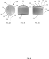
- FIGS. 3A, 3B, and 3C illustrate perspective, face, and side views respectively of an embodiment of a PDC cutting element 300, in accordance with the present disclosure, in which four concave subtractions or cutouts have been taken from diamond table 304, thus defining three concave indentations 308 and a concave surface 302.
- the concave indentations 308 form three edges of the concave surface 302 and extend from the concave surface 302 radially outward to an outer diameter of the diamond table 304 (or longitudinal side surface 314 of the PDC cutting element 200).
- the PDC cutting element 300 comprises a diamond table 304 bonded to a substrate 306 at an interface 312.
- the total thickness of the diamond table 304 may be between 1 mm and 10 mm, more preferably between 2 mm and 5 mm, more preferably about 3 mm to 3.5 mm.
- the top surface of the diamond table 304 comprises a concave surface 302, three concave indentations 308, and three cutting edges 310.
- the three concave indentations 308 extend from a concave surface 302 that is roughly triangular with curved edges.
- the concave surface defines a portion of a sphere.
- FIGS. 3A, 3B, and 3C also illustrate three concave indentations 308 that are spaced equidistantly from each other around an outer edge of the diamond table and do not meet or merge into each other.
- the concave indentations 308 may not be spaced equidistantly from each other around an outer edge of the diamond table and may meet or merge into each other. In some embodiments, there may be four or more concave indentations. In some embodiments, the concave indentations 308 may extend into as much as 95% of the thickness of the diamond table 304. The concave indentations each define a portion of a sphere.
- the concave surface 302 is symmetric about line 318 and extends from one side of the diamond table 304 to the opposite side of the diamond table.
- the concave surface 302 is concave or dish-like.
- concave surface 302 may extend to the outer diameter or longitudinal side surface 314 of the PDC cutting element 300.
- the concave surface 302 may comprise between about 10% and 90% of the overall surface area of the diamond table 304 and may extend down into as much as 25% of the thickness of the diamond table 304.
- the concave indentations 308 and the concave surface 302 may be formed in the diamond table 304 by grinding, machining, milling, or any other suitable method known in the art to remove polycrystalline diamond material. Furthermore, the order in which the concave subtractions are formed does not matter. The grinding, milling, or machining etc. to form the concave subtraction surfaces may be done in any order, or the surfaces may be formed substantially simultaneously.
- FIGS. 3A, 3B, and 3C also illustrate three cutting edges 310 disposed at an interface between the concave surface 302 and the outer diameter of the diamond table 304 (or longitudinal side surface 314 of the cutting element 300).
- the optimal orientation for PDC cutting element 300 is to have one of the cutting edges 310 oriented (or pointed) towards the formation material to be drilled.
- the PDC cutting element 300 When significant abrasion has worn down a first of the cutting edges 310 of the PDC cutting element 300, the PDC cutting element 300 may be rotated by removing the drill bit, and by removing, rotating, and reattaching the PDC cutting element 300 on the drill bit in order to orient a second (and then a third etc.) of the cutting edges 310 towards the formation material to be drilled.
- the concave indentations 308 may be configured and oriented to improve the flow of the drilling fluid and formation cuttings around the face of the cutting element 300.
- a typical rotary-type "drag" bit made from steel and using PDC cutting elements is described.
- the size, shape, and/or configuration of the bit may vary according to operational design parameters.
Landscapes
- Engineering & Computer Science (AREA)
- Life Sciences & Earth Sciences (AREA)
- Mining & Mineral Resources (AREA)
- Geology (AREA)
- Physics & Mathematics (AREA)
- Chemical & Material Sciences (AREA)
- Environmental & Geological Engineering (AREA)
- Fluid Mechanics (AREA)
- Mechanical Engineering (AREA)
- Crystallography & Structural Chemistry (AREA)
- General Life Sciences & Earth Sciences (AREA)
- Geochemistry & Mineralogy (AREA)
- Earth Drilling (AREA)
- Processing Of Stones Or Stones Resemblance Materials (AREA)
- Drilling Tools (AREA)
- Cutting Tools, Boring Holders, And Turrets (AREA)
- Polishing Bodies And Polishing Tools (AREA)
Claims (15)
- Élément de coupe (200 ; 300) comprenant :un substrat (210) ; 306) ; etune table de diamant (212 ; 304) ayant une première extrémité et une seconde extrémité, la première extrémité de la table de diamant (212 ; 304) étant fixée au substrat (210 ; 306) au niveau d'une première interface (214 ; 312), la seconde extrémité de la table de diamant (212 ; 304) comprenant :une surface concave (202 ; 302) ;au moins deux indentations concaves (216 ; 308), chacune des au moins deux indentations concaves (216 ; 308) recoupant la surface concave (202 ; 302) pour s'étendre radialement vers l'extérieur à partir de la surface concave (202 ; 302) jusqu'à un diamètre extérieur de la table de diamant (212 ; 304) ; etau moins deux bords de coupe (206 ; 310) au niveau d'une interface (214 ; 312) entre la surface concave (202 ; 302) et le diamètre extérieur de la table de diamant (212 ; 304) ; caractérisé en ce quela surface concave (202 ; 302) et les indentations concaves (216 ; 308) définissent chacune respectivement une partie d'une sphère.
- Élément de coupe (200 ; 300) selon la revendication 1, dans lequel la surface concave (202 ; 302) a un rayon de courbure compris entre 5 millimètres et 250 millimètres.
- Élément de coupe (200 ; 300) selon la revendication 1 ou 2, dans lequel la surface concave (202 ; 302) couvre entre 10 % et 90 % de la surface totale de la seconde extrémité de la table de diamant (212 ; 304).
- Élément de coupe (200 ; 300) selon la revendication 1, 2 ou 3, dans lequel chacune des au moins deux indentations concaves (216 ; 308) a un rayon de courbure compris entre 5 millimètres et 125 millimètres.
- Élément de coupe (200 ; 300) selon l'une quelconque revendication précédente, dans lequel chacune des au moins deux indentations concaves (216 ; 308) s'étend dans la table de diamant (212 ; 304) jusqu'à une profondeur allant jusqu'à 95 % d'une épaisseur de la table de diamant (212 ; 304).
- Élément de coupe (200 ; 300) selon l'une quelconque revendication précédente, dans lequel les au moins deux indentations concaves (216 ; 308) ne se fondent pas l'une dans l'autre.
- Élément de coupe (200 ; 300) selon l'une quelconque revendication précédente, dans lequel chacune des au moins deux indentations concaves (216 ; 308) sont espacées de manière équidistantes l'une de l'autre autour du diamètre extérieur de la table de diamant (212 ; 304).
- Élément de coupe (200 ; 300) selon l'une quelconque revendication précédente, dans lequel les au moins deux bords de coupe (206 ; 310) sont chanfreinés.
- Élément de coupe (200 ; 300) selon l'une quelconque revendication précédente, dans lequel les au moins deux indentations concaves (216 ; 308) comprennent trois indentations concaves (216 ; 308).
- Élément de coupe (200 ; 300) selon la revendication 9, dans lequel chacune des au moins trois indentations concaves (216 ; 308) ne se fondent pas l'une dans l'autre.
- Élément de coupe (200 ; 300) selon la revendication 9 ou 10, dans lequel chacune des au moins trois indentations concaves (216 ; 308) sont espacées de manière équidistantes l'une de l'autre autour du diamètre extérieur de la table de diamant (212 ; 304).
- Procédé de fabrication d'un outil de fond de trou de forage comprenant : la fourniture d'un corps d'outil ; et
la fixation d'un élément de coupe (200 ; 300), selon l'une quelconque des revendications 1 à 11, au corps de l'outil. - Procédé selon la revendication 12, comprenant en outre la formation de la surface concave (202 ; 302) et/ou les au moins deux indentations concaves (216 ; 308) par broyage.
- Procédé selon la revendication 12 ou 13, comprenant en outre la formation de la surface concave (202 ; 302) et/ou les au moins deux indentations concaves (216 ; 308) par usinage par étincelage (EDM).
- Procédés selon les revendications 12, 13 ou 14, comprenant en outre la formation de la surface concave (202 ; 302) et/ou les au moins deux indentations concaves (216 ; 308) par élimination au laser.
Applications Claiming Priority (1)
| Application Number | Priority Date | Filing Date | Title |
|---|---|---|---|
| PCT/US2020/016826 WO2021158215A1 (fr) | 2020-02-05 | 2020-02-05 | Géométrie de coupe utilisant des découpes sphériques |
Publications (3)
| Publication Number | Publication Date |
|---|---|
| EP4100613A1 EP4100613A1 (fr) | 2022-12-14 |
| EP4100613A4 EP4100613A4 (fr) | 2023-10-18 |
| EP4100613B1 true EP4100613B1 (fr) | 2025-01-22 |
Family
ID=77200213
Family Applications (1)
| Application Number | Title | Priority Date | Filing Date |
|---|---|---|---|
| EP20917982.9A Active EP4100613B1 (fr) | 2020-02-05 | 2020-02-05 | Géométrie de coupe utilisant des découpes sphériques |
Country Status (5)
| Country | Link |
|---|---|
| US (1) | US12049788B2 (fr) |
| EP (1) | EP4100613B1 (fr) |
| CN (1) | CN114981518A (fr) |
| CA (1) | CA3165510A1 (fr) |
| WO (1) | WO2021158215A1 (fr) |
Families Citing this family (4)
| Publication number | Priority date | Publication date | Assignee | Title |
|---|---|---|---|---|
| USD924949S1 (en) | 2019-01-11 | 2021-07-13 | Us Synthetic Corporation | Cutting tool |
| USD1026979S1 (en) | 2020-12-03 | 2024-05-14 | Us Synthetic Corporation | Cutting tool |
| WO2024112905A1 (fr) * | 2022-11-22 | 2024-05-30 | Baker Hughes Oilfield Operations Llc | Éléments de coupe et géométries pour vibrations réduites, outils de forage et procédés associés |
| US11993986B1 (en) * | 2023-01-18 | 2024-05-28 | Alaskan Energy Resources, Inc. | System, method and apparatus for a protection clamp for pipe |
Family Cites Families (91)
| Publication number | Priority date | Publication date | Assignee | Title |
|---|---|---|---|---|
| US4109737A (en) | 1976-06-24 | 1978-08-29 | General Electric Company | Rotary drill bit |
| US4570726A (en) | 1982-10-06 | 1986-02-18 | Megadiamond Industries, Inc. | Curved contact portion on engaging elements for rotary type drag bits |
| US4529048A (en) | 1982-10-06 | 1985-07-16 | Megadiamond Industries, Inc. | Inserts having two components anchored together at a non-perpendicular angle of attachment for use in rotary type drag bits |
| US4593777A (en) | 1983-02-22 | 1986-06-10 | Nl Industries, Inc. | Drag bit and cutters |
| US4872520A (en) | 1987-01-16 | 1989-10-10 | Triton Engineering Services Company | Flat bottom drilling bit with polycrystalline cutters |
| US5467836A (en) | 1992-01-31 | 1995-11-21 | Baker Hughes Incorporated | Fixed cutter bit with shear cutting gage |
| US5314033A (en) | 1992-02-18 | 1994-05-24 | Baker Hughes Incorporated | Drill bit having combined positive and negative or neutral rake cutters |
| US5437343A (en) | 1992-06-05 | 1995-08-01 | Baker Hughes Incorporated | Diamond cutters having modified cutting edge geometry and drill bit mounting arrangement therefor |
| US5333699A (en) | 1992-12-23 | 1994-08-02 | Baroid Technology, Inc. | Drill bit having polycrystalline diamond compact cutter with spherical first end opposite cutting end |
| WO1994015058A1 (fr) | 1992-12-23 | 1994-07-07 | Baroid Technology, Inc. | Trepan comportant un broyeur de fragments a couche compacte diamantee polycristalline et un insert metallique dur au niveau d'une surface etalon |
| US5460233A (en) | 1993-03-30 | 1995-10-24 | Baker Hughes Incorporated | Diamond cutting structure for drilling hard subterranean formations |
| US5379854A (en) | 1993-08-17 | 1995-01-10 | Dennis Tool Company | Cutting element for drill bits |
| US5706906A (en) | 1996-02-15 | 1998-01-13 | Baker Hughes Incorporated | Superabrasive cutting element with enhanced durability and increased wear life, and apparatus so equipped |
| GB9621217D0 (en) | 1996-10-11 | 1996-11-27 | Camco Drilling Group Ltd | Improvements in or relating to preform cutting elements for rotary drill bits |
| US5881830A (en) | 1997-02-14 | 1999-03-16 | Baker Hughes Incorporated | Superabrasive drill bit cutting element with buttress-supported planar chamfer |
| US5871060A (en) | 1997-02-20 | 1999-02-16 | Jensen; Kenneth M. | Attachment geometry for non-planar drill inserts |
| US6045440A (en) | 1997-11-20 | 2000-04-04 | General Electric Company | Polycrystalline diamond compact PDC cutter with improved cutting capability |
| US6196340B1 (en) | 1997-11-28 | 2001-03-06 | U.S. Synthetic Corporation | Surface geometry for non-planar drill inserts |
| CA2276841C (fr) * | 1998-07-07 | 2004-12-14 | Smith International, Inc. | Insertions non planaires et non axisymetriques |
| US6447560B2 (en) | 1999-02-19 | 2002-09-10 | Us Synthetic Corporation | Method for forming a superabrasive polycrystalline cutting tool with an integral chipbreaker feature |
| DE19928367A1 (de) | 1999-06-21 | 2000-12-28 | Will E C H Gmbh & Co | Verfahren und Vorrichtung zum Wechseln von Paletten für Bogenstapel |
| US6460631B2 (en) | 1999-08-26 | 2002-10-08 | Baker Hughes Incorporated | Drill bits with reduced exposure of cutters |
| US6743158B2 (en) | 2000-03-01 | 2004-06-01 | Cybex Interational, Inc. | Leg press |
| WO2002038544A2 (fr) | 2000-11-10 | 2002-05-16 | Eli Lilly And Company | Agonistes du recepteur beta-3 d'oxindole 3-substitue |
| US6550556B2 (en) | 2000-12-07 | 2003-04-22 | Smith International, Inc | Ultra hard material cutter with shaped cutting surface |
| US6510910B2 (en) | 2001-02-09 | 2003-01-28 | Smith International, Inc. | Unplanar non-axisymmetric inserts |
| US6513608B2 (en) | 2001-02-09 | 2003-02-04 | Smith International, Inc. | Cutting elements with interface having multiple abutting depressions |
| US6929079B2 (en) | 2003-02-21 | 2005-08-16 | Smith International, Inc. | Drill bit cutter element having multiple cusps |
| DE10361450A1 (de) | 2003-12-23 | 2005-07-28 | EMUGE-Werk Richard Glimpel GmbH & Co. KG Fabrik für Präzisionswerkzeuge | Schneidelement und Werkzeug mit wenigstens einem Schneidelement |
| US7798257B2 (en) | 2004-04-30 | 2010-09-21 | Smith International, Inc. | Shaped cutter surface |
| US20050247486A1 (en) | 2004-04-30 | 2005-11-10 | Smith International, Inc. | Modified cutters |
| US7726420B2 (en) | 2004-04-30 | 2010-06-01 | Smith International, Inc. | Cutter having shaped working surface with varying edge chamfer |
| US20080264696A1 (en) | 2005-12-20 | 2008-10-30 | Varel International, Ind., L.P. | Auto adaptable cutting structure |
| US7363992B2 (en) | 2006-07-07 | 2008-04-29 | Baker Hughes Incorporated | Cutters for downhole cutting devices |
| US8016059B2 (en) | 2007-02-09 | 2011-09-13 | Smith International, Inc. | Gage insert |
| US8783387B2 (en) | 2008-09-05 | 2014-07-22 | Smith International, Inc. | Cutter geometry for high ROP applications |
| US8833492B2 (en) | 2008-10-08 | 2014-09-16 | Smith International, Inc. | Cutters for fixed cutter bits |
| CN101560869B (zh) | 2009-05-27 | 2012-04-04 | 江汉石油钻头股份有限公司 | 凸顶偏楔齿 |
| US8739904B2 (en) | 2009-08-07 | 2014-06-03 | Baker Hughes Incorporated | Superabrasive cutters with grooves on the cutting face, and drill bits and drilling tools so equipped |
| EP2561171B1 (fr) * | 2010-04-23 | 2018-01-10 | Baker Hughes, a GE company, LLC | Eléments de coupe destinés à des outils de forage, outils de forage incluant lesdits éléments de coupe et procédés connexes |
| RU2012151373A (ru) | 2010-05-03 | 2014-06-10 | Бейкер Хьюз Инкорпорейтед | Режущий элемент, бурильный инструмент и способы их формирования |
| US8936109B2 (en) | 2010-06-24 | 2015-01-20 | Baker Hughes Incorporated | Cutting elements for cutting tools |
| US9650837B2 (en) | 2011-04-22 | 2017-05-16 | Baker Hughes Incorporated | Multi-chamfer cutting elements having a shaped cutting face and earth-boring tools including such cutting elements |
| US9103174B2 (en) | 2011-04-22 | 2015-08-11 | Baker Hughes Incorporated | Cutting elements for earth-boring tools, earth-boring tools including such cutting elements and related methods |
| US9482057B2 (en) | 2011-09-16 | 2016-11-01 | Baker Hughes Incorporated | Cutting elements for earth-boring tools, earth-boring tools including such cutting elements and related methods |
| US9441422B2 (en) | 2012-08-29 | 2016-09-13 | National Oilwell DHT, L.P. | Cutting insert for a rock drill bit |
| US10309156B2 (en) | 2013-03-14 | 2019-06-04 | Smith International, Inc. | Cutting structures for fixed cutter drill bit and other downhole cutting tools |
| US10022840B1 (en) * | 2013-10-16 | 2018-07-17 | Us Synthetic Corporation | Polycrystalline diamond compact including crack-resistant polycrystalline diamond table |
| KR20150096542A (ko) | 2014-02-14 | 2015-08-25 | 일진다이아몬드(주) | 다결정 다이아몬드 컴팩트 및 그 제조방법 |
| US10287825B2 (en) | 2014-03-11 | 2019-05-14 | Smith International, Inc. | Cutting elements having non-planar surfaces and downhole cutting tools using such cutting elements |
| US9845642B2 (en) | 2014-03-17 | 2017-12-19 | Baker Hughes Incorporated | Cutting elements having non-planar cutting faces with selectively leached regions, earth-boring tools including such cutting elements, and related methods |
| AU2015247624B2 (en) | 2014-04-16 | 2019-01-31 | National Oilwell DHT, L.P. | Downhole drill bit cutting element with chamfered ridge |
| US10465447B2 (en) * | 2015-03-12 | 2019-11-05 | Baker Hughes, A Ge Company, Llc | Cutting elements configured to mitigate diamond table failure, earth-boring tools including such cutting elements, and related methods |
| US10526850B2 (en) | 2015-06-18 | 2020-01-07 | Halliburton Energy Services, Inc. | Drill bit cutter having shaped cutting element |
| US10386801B2 (en) | 2015-08-03 | 2019-08-20 | Baker Hughes, A Ge Company, Llc | Methods of forming and methods of repairing earth-boring tools |
| US10907416B2 (en) | 2015-08-27 | 2021-02-02 | Cnpc Usa Corporation | Polycrystalline diamond cutter with improved geometry for cooling and cutting evacuation and efficiency and durability |
| CN105156036B (zh) | 2015-08-27 | 2018-01-05 | 中国石油天然气集团公司 | 凸脊型非平面切削齿及金刚石钻头 |
| US10563464B2 (en) | 2015-08-27 | 2020-02-18 | Cnpc Usa Corporation | Convex ridge type non-planar cutting tooth and diamond drill bit |
| WO2017053475A1 (fr) | 2015-09-21 | 2017-03-30 | National Oilwell DHT, L.P. | Trépan fond de trou doté d'éléments de coupe équilibrés et procédé de fabrication et d'utilisation correspondant |
| CN108291427B (zh) | 2015-11-19 | 2021-01-05 | 史密斯国际有限公司 | 上面具有非平面切削元件的固定切削刀钻头以及其它井下工具 |
| US11814904B2 (en) | 2015-11-30 | 2023-11-14 | Schlumberger Technology Corporation | Cutting structure of cutting elements for downhole cutting tools |
| US11091960B2 (en) | 2015-12-18 | 2021-08-17 | Schlumberger Technology Corporation | Placement of non-planar cutting elements |
| CN205259954U (zh) | 2015-12-24 | 2016-05-25 | 河南四方达超硬材料股份有限公司 | 一种多刃异形结构聚晶金刚石复合片 |
| US10907415B2 (en) | 2016-03-31 | 2021-02-02 | Smith International, Inc. | Multiple ridge cutting element |
| CN205778558U (zh) * | 2016-05-30 | 2016-12-07 | 成都百施特金刚石钻头有限公司 | 脊形切削齿 |
| WO2018147959A1 (fr) | 2017-02-09 | 2018-08-16 | Us Synthetic Corporation | Comprimés de diamant polycristallin usinés par une source d'énergie et procédés associés |
| US11873684B2 (en) | 2017-03-14 | 2024-01-16 | Sf Diamond Co., Ltd. | Polycrystalline diamond compact |
| US10400517B2 (en) | 2017-05-02 | 2019-09-03 | Baker Hughes, A Ge Company, Llc | Cutting elements configured to reduce impact damage and related tools and methods |
| US10605010B2 (en) | 2017-06-13 | 2020-03-31 | Varel Europe S.A.S. | Fixed cutter drill bit having cutter orienting system |
| US11060356B2 (en) | 2017-06-13 | 2021-07-13 | Varel International Ind., L.L.C. | Superabrasive cutters for earth boring bits with multiple raised cutting surfaces |
| CA3012543A1 (fr) | 2017-08-23 | 2019-02-23 | Varel International Ind., L.L.C. | Foret presentant un couteau avant forme et un couteau arriere enduit |
| US11098532B2 (en) | 2017-09-05 | 2021-08-24 | Schlumberger Technology Corporation | Cutting elements having non-planar surfaces and tools incorporating the same |
| CN207728311U (zh) | 2017-12-26 | 2018-08-14 | 中石化江钻石油机械有限公司 | 一种金刚石复合片 |
| CN108661565B (zh) | 2018-07-13 | 2021-11-16 | 中石化江钻石油机械有限公司 | 一种多脊金刚石复合片 |
| US10570668B2 (en) | 2018-07-27 | 2020-02-25 | Baker Hughes, A Ge Company, Llc | Cutting elements configured to reduce impact damage and mitigate polycrystalline, superabrasive material failure earth-boring tools including such cutting elements, and related methods |
| EP3850182B1 (fr) | 2018-09-10 | 2024-07-17 | National Oilwell Varco, LP | Éléments de coupe pour trépan et trépans équipés desdits éléments de coupe |
| CN113286930A (zh) | 2018-11-12 | 2021-08-20 | 斯伦贝谢技术有限公司 | 具有非平面界面设计的非平面切割元件和包含这种元件的刀具 |
| WO2020131421A2 (fr) | 2018-12-17 | 2020-06-25 | Diamond Innovations, Inc. | Dispositifs de coupe en diamant polycristallin prѐs de la forme désirée et leurs procédés de fabrication |
| US11255129B2 (en) | 2019-01-16 | 2022-02-22 | Ulterra Drilling Technologies, L.P. | Shaped cutters |
| US11035177B2 (en) | 2019-01-16 | 2021-06-15 | Ulterra Drilling Technologies L.P. | Shaped cutters |
| GB201907976D0 (en) | 2019-06-04 | 2019-07-17 | Element Six Uk Ltd | A cutting element and methods of making same |
| GB201907970D0 (en) | 2019-06-04 | 2019-07-17 | Element Six Uk Ltd | A cutting element and method of making same |
| US12078015B2 (en) | 2019-08-30 | 2024-09-03 | Schlumberger Technology Corporation | Polycrystalline diamond cutting element having improved cutting efficiency |
| WO2021080900A1 (fr) | 2019-10-21 | 2021-04-29 | Smith International Inc. | Dispositif de coupe à bords de coupe géométriques |
| US11208849B2 (en) | 2019-11-04 | 2021-12-28 | National Oilwell DHT, L.P. | Drill bit cutter elements and drill bits including same |
| US11661799B2 (en) | 2019-12-12 | 2023-05-30 | Cnpc Usa Corporation | Shaped cutter with alignment structure for drill bit and assembly method thereof |
| US11578538B2 (en) | 2020-01-09 | 2023-02-14 | Schlumberger Technology Corporation | Cutting element with nonplanar face to improve cutting efficiency and durability |
| EP4100612B1 (fr) | 2020-02-05 | 2025-08-20 | Baker Hughes Oilfield Operations LLC | Élément de coupe à efficacité mécanique améliorée |
| WO2021178304A1 (fr) | 2020-03-02 | 2021-09-10 | Schlumberger Technology Corporation | Élément en forme d'arête |
| CN113738284B (zh) | 2020-05-27 | 2024-05-28 | 中国石油天然气股份有限公司 | 切削齿及具有其的钻头 |
| CN113738285A (zh) | 2020-05-27 | 2021-12-03 | 中国石油天然气集团有限公司 | 具有切削脊和倾斜切削面的复合片及pdc钻头 |
-
2020
- 2020-02-05 WO PCT/US2020/016826 patent/WO2021158215A1/fr not_active Ceased
- 2020-02-05 CN CN202080093492.7A patent/CN114981518A/zh active Pending
- 2020-02-05 US US17/759,755 patent/US12049788B2/en active Active
- 2020-02-05 CA CA3165510A patent/CA3165510A1/fr active Pending
- 2020-02-05 EP EP20917982.9A patent/EP4100613B1/fr active Active
Also Published As
| Publication number | Publication date |
|---|---|
| WO2021158215A1 (fr) | 2021-08-12 |
| EP4100613A1 (fr) | 2022-12-14 |
| US12049788B2 (en) | 2024-07-30 |
| CA3165510A1 (fr) | 2021-08-12 |
| CN114981518A (zh) | 2022-08-30 |
| US20230064436A1 (en) | 2023-03-02 |
| EP4100613A4 (fr) | 2023-10-18 |
Similar Documents
| Publication | Publication Date | Title |
|---|---|---|
| EP4100612B1 (fr) | Élément de coupe à efficacité mécanique améliorée | |
| CA2873450C (fr) | Elements de coupe destines a des outils de forage du sol, outils de forage du sol comprenant de tels elements de coupe, et procedes apparentes | |
| US10450807B2 (en) | Earth-boring tools having shaped cutting elements | |
| EP3191677B1 (fr) | Éléments de coupe à chanfreins multiples ayant une face de coupe mise en forme, outils de forage comprenant de tels éléments de coupe | |
| CN112437827B (zh) | 被构造成减少冲击损坏的切削元件以及相关工具和方法-另选构型 | |
| US12134938B2 (en) | Cutting elements for earth-boring tools, methods of manufacturing earth-boring tools, and related earth-boring tools | |
| US20150218890A1 (en) | Earth-boring tools including shaped cutting elements, and related methods | |
| EP4100613B1 (fr) | Géométrie de coupe utilisant des découpes sphériques | |
| US12227994B2 (en) | Cutting elements and geometries, earth-boring tools, and related methods | |
| US12320199B1 (en) | Cutting elements and geometries for reduced vibrations, earth-boring tools, and related methods | |
| US11920409B2 (en) | Cutting elements, earth-boring tools including the cutting elements, and methods of forming the earth-boring tools | |
| WO2024054231A1 (fr) | Géométrie d'outil de forage et placement de dispositif de coupe, et appareil et procédés associés | |
| US11585157B2 (en) | Earth boring tools with enhanced hydraulics adjacent cutting elements and methods of forming |
Legal Events
| Date | Code | Title | Description |
|---|---|---|---|
| STAA | Information on the status of an ep patent application or granted ep patent |
Free format text: STATUS: THE INTERNATIONAL PUBLICATION HAS BEEN MADE |
|
| PUAI | Public reference made under article 153(3) epc to a published international application that has entered the european phase |
Free format text: ORIGINAL CODE: 0009012 |
|
| STAA | Information on the status of an ep patent application or granted ep patent |
Free format text: STATUS: REQUEST FOR EXAMINATION WAS MADE |
|
| 17P | Request for examination filed |
Effective date: 20220818 |
|
| AK | Designated contracting states |
Kind code of ref document: A1 Designated state(s): AL AT BE BG CH CY CZ DE DK EE ES FI FR GB GR HR HU IE IS IT LI LT LU LV MC MK MT NL NO PL PT RO RS SE SI SK SM TR |
|
| DAV | Request for validation of the european patent (deleted) | ||
| DAX | Request for extension of the european patent (deleted) | ||
| P01 | Opt-out of the competence of the unified patent court (upc) registered |
Effective date: 20230526 |
|
| A4 | Supplementary search report drawn up and despatched |
Effective date: 20230918 |
|
| RIC1 | Information provided on ipc code assigned before grant |
Ipc: E21B 10/55 20060101ALI20230912BHEP Ipc: E21B 10/54 20060101ALI20230912BHEP Ipc: E21B 10/48 20060101ALI20230912BHEP Ipc: E21B 10/46 20060101ALI20230912BHEP Ipc: E21B 10/42 20060101ALI20230912BHEP Ipc: E21B 10/567 20060101AFI20230912BHEP |
|
| GRAP | Despatch of communication of intention to grant a patent |
Free format text: ORIGINAL CODE: EPIDOSNIGR1 |
|
| STAA | Information on the status of an ep patent application or granted ep patent |
Free format text: STATUS: GRANT OF PATENT IS INTENDED |
|
| INTG | Intention to grant announced |
Effective date: 20240919 |
|
| GRAS | Grant fee paid |
Free format text: ORIGINAL CODE: EPIDOSNIGR3 |
|
| GRAA | (expected) grant |
Free format text: ORIGINAL CODE: 0009210 |
|
| STAA | Information on the status of an ep patent application or granted ep patent |
Free format text: STATUS: THE PATENT HAS BEEN GRANTED |
|
| AK | Designated contracting states |
Kind code of ref document: B1 Designated state(s): AL AT BE BG CH CY CZ DE DK EE ES FI FR GB GR HR HU IE IS IT LI LT LU LV MC MK MT NL NO PL PT RO RS SE SI SK SM TR |
|
| REG | Reference to a national code |
Ref country code: GB Ref legal event code: FG4D |
|
| REG | Reference to a national code |
Ref country code: CH Ref legal event code: EP |
|
| REG | Reference to a national code |
Ref country code: IE Ref legal event code: FG4D |
|
| REG | Reference to a national code |
Ref country code: DE Ref legal event code: R096 Ref document number: 602020045370 Country of ref document: DE |
|
| REG | Reference to a national code |
Ref country code: SE Ref legal event code: TRGR |
|
| REG | Reference to a national code |
Ref country code: NL Ref legal event code: MP Effective date: 20250122 |
|
| PG25 | Lapsed in a contracting state [announced via postgrant information from national office to epo] |
Ref country code: NL Free format text: LAPSE BECAUSE OF FAILURE TO SUBMIT A TRANSLATION OF THE DESCRIPTION OR TO PAY THE FEE WITHIN THE PRESCRIBED TIME-LIMIT Effective date: 20250122 |
|
| PG25 | Lapsed in a contracting state [announced via postgrant information from national office to epo] |
Ref country code: RS Free format text: LAPSE BECAUSE OF FAILURE TO SUBMIT A TRANSLATION OF THE DESCRIPTION OR TO PAY THE FEE WITHIN THE PRESCRIBED TIME-LIMIT Effective date: 20250422 |
|
| PG25 | Lapsed in a contracting state [announced via postgrant information from national office to epo] |
Ref country code: FI Free format text: LAPSE BECAUSE OF FAILURE TO SUBMIT A TRANSLATION OF THE DESCRIPTION OR TO PAY THE FEE WITHIN THE PRESCRIBED TIME-LIMIT Effective date: 20250122 |
|
| PG25 | Lapsed in a contracting state [announced via postgrant information from national office to epo] |
Ref country code: PL Free format text: LAPSE BECAUSE OF FAILURE TO SUBMIT A TRANSLATION OF THE DESCRIPTION OR TO PAY THE FEE WITHIN THE PRESCRIBED TIME-LIMIT Effective date: 20250122 |
|
| PG25 | Lapsed in a contracting state [announced via postgrant information from national office to epo] |
Ref country code: ES Free format text: LAPSE BECAUSE OF FAILURE TO SUBMIT A TRANSLATION OF THE DESCRIPTION OR TO PAY THE FEE WITHIN THE PRESCRIBED TIME-LIMIT Effective date: 20250122 |
|
| REG | Reference to a national code |
Ref country code: LT Ref legal event code: MG9D |
|
| PG25 | Lapsed in a contracting state [announced via postgrant information from national office to epo] |
Ref country code: IS Free format text: LAPSE BECAUSE OF FAILURE TO SUBMIT A TRANSLATION OF THE DESCRIPTION OR TO PAY THE FEE WITHIN THE PRESCRIBED TIME-LIMIT Effective date: 20250522 |
|
| REG | Reference to a national code |
Ref country code: AT Ref legal event code: MK05 Ref document number: 1761608 Country of ref document: AT Kind code of ref document: T Effective date: 20250122 |
|
| PG25 | Lapsed in a contracting state [announced via postgrant information from national office to epo] |
Ref country code: HR Free format text: LAPSE BECAUSE OF FAILURE TO SUBMIT A TRANSLATION OF THE DESCRIPTION OR TO PAY THE FEE WITHIN THE PRESCRIBED TIME-LIMIT Effective date: 20250122 |
|
| PG25 | Lapsed in a contracting state [announced via postgrant information from national office to epo] |
Ref country code: LV Free format text: LAPSE BECAUSE OF FAILURE TO SUBMIT A TRANSLATION OF THE DESCRIPTION OR TO PAY THE FEE WITHIN THE PRESCRIBED TIME-LIMIT Effective date: 20250122 Ref country code: PT Free format text: LAPSE BECAUSE OF FAILURE TO SUBMIT A TRANSLATION OF THE DESCRIPTION OR TO PAY THE FEE WITHIN THE PRESCRIBED TIME-LIMIT Effective date: 20250522 |
|
| PG25 | Lapsed in a contracting state [announced via postgrant information from national office to epo] |
Ref country code: BG Free format text: LAPSE BECAUSE OF FAILURE TO SUBMIT A TRANSLATION OF THE DESCRIPTION OR TO PAY THE FEE WITHIN THE PRESCRIBED TIME-LIMIT Effective date: 20250122 Ref country code: GR Free format text: LAPSE BECAUSE OF FAILURE TO SUBMIT A TRANSLATION OF THE DESCRIPTION OR TO PAY THE FEE WITHIN THE PRESCRIBED TIME-LIMIT Effective date: 20250423 |
|
| PG25 | Lapsed in a contracting state [announced via postgrant information from national office to epo] |
Ref country code: AT Free format text: LAPSE BECAUSE OF FAILURE TO SUBMIT A TRANSLATION OF THE DESCRIPTION OR TO PAY THE FEE WITHIN THE PRESCRIBED TIME-LIMIT Effective date: 20250122 |
|
| REG | Reference to a national code |
Ref country code: DE Ref legal event code: R119 Ref document number: 602020045370 Country of ref document: DE |
|
| REG | Reference to a national code |
Ref country code: CH Ref legal event code: PL |
|
| PG25 | Lapsed in a contracting state [announced via postgrant information from national office to epo] |
Ref country code: SM Free format text: LAPSE BECAUSE OF FAILURE TO SUBMIT A TRANSLATION OF THE DESCRIPTION OR TO PAY THE FEE WITHIN THE PRESCRIBED TIME-LIMIT Effective date: 20250122 |
|
| PG25 | Lapsed in a contracting state [announced via postgrant information from national office to epo] |
Ref country code: DK Free format text: LAPSE BECAUSE OF FAILURE TO SUBMIT A TRANSLATION OF THE DESCRIPTION OR TO PAY THE FEE WITHIN THE PRESCRIBED TIME-LIMIT Effective date: 20250122 |
|
| PG25 | Lapsed in a contracting state [announced via postgrant information from national office to epo] |
Ref country code: MC Free format text: LAPSE BECAUSE OF FAILURE TO SUBMIT A TRANSLATION OF THE DESCRIPTION OR TO PAY THE FEE WITHIN THE PRESCRIBED TIME-LIMIT Effective date: 20250122 |
|
| PG25 | Lapsed in a contracting state [announced via postgrant information from national office to epo] |
Ref country code: IT Free format text: LAPSE BECAUSE OF FAILURE TO SUBMIT A TRANSLATION OF THE DESCRIPTION OR TO PAY THE FEE WITHIN THE PRESCRIBED TIME-LIMIT Effective date: 20250122 Ref country code: LU Free format text: LAPSE BECAUSE OF NON-PAYMENT OF DUE FEES Effective date: 20250205 |
|
| PG25 | Lapsed in a contracting state [announced via postgrant information from national office to epo] |
Ref country code: CH Free format text: LAPSE BECAUSE OF NON-PAYMENT OF DUE FEES Effective date: 20250228 |
|
| PG25 | Lapsed in a contracting state [announced via postgrant information from national office to epo] |
Ref country code: CZ Free format text: LAPSE BECAUSE OF FAILURE TO SUBMIT A TRANSLATION OF THE DESCRIPTION OR TO PAY THE FEE WITHIN THE PRESCRIBED TIME-LIMIT Effective date: 20250122 Ref country code: EE Free format text: LAPSE BECAUSE OF FAILURE TO SUBMIT A TRANSLATION OF THE DESCRIPTION OR TO PAY THE FEE WITHIN THE PRESCRIBED TIME-LIMIT Effective date: 20250122 |
|
| PG25 | Lapsed in a contracting state [announced via postgrant information from national office to epo] |
Ref country code: RO Free format text: LAPSE BECAUSE OF FAILURE TO SUBMIT A TRANSLATION OF THE DESCRIPTION OR TO PAY THE FEE WITHIN THE PRESCRIBED TIME-LIMIT Effective date: 20250122 |
|
| PG25 | Lapsed in a contracting state [announced via postgrant information from national office to epo] |
Ref country code: SK Free format text: LAPSE BECAUSE OF FAILURE TO SUBMIT A TRANSLATION OF THE DESCRIPTION OR TO PAY THE FEE WITHIN THE PRESCRIBED TIME-LIMIT Effective date: 20250122 |
|
| PLBE | No opposition filed within time limit |
Free format text: ORIGINAL CODE: 0009261 |
|
| STAA | Information on the status of an ep patent application or granted ep patent |
Free format text: STATUS: NO OPPOSITION FILED WITHIN TIME LIMIT |
|
| REG | Reference to a national code |
Ref country code: SE Ref legal event code: EUG |
|
| REG | Reference to a national code |
Ref country code: BE Ref legal event code: MM Effective date: 20250228 |
|
| GBPC | Gb: european patent ceased through non-payment of renewal fee |
Effective date: 20250422 |
|
| 26N | No opposition filed |
Effective date: 20251023 |
|
| PG25 | Lapsed in a contracting state [announced via postgrant information from national office to epo] |
Ref country code: DE Free format text: LAPSE BECAUSE OF NON-PAYMENT OF DUE FEES Effective date: 20250902 |
|
| PG25 | Lapsed in a contracting state [announced via postgrant information from national office to epo] |
Ref country code: GB Free format text: LAPSE BECAUSE OF NON-PAYMENT OF DUE FEES Effective date: 20250422 |
|
| PG25 | Lapsed in a contracting state [announced via postgrant information from national office to epo] |
Ref country code: NO Free format text: LAPSE BECAUSE OF NON-PAYMENT OF DUE FEES Effective date: 20250422 |
|
| PG25 | Lapsed in a contracting state [announced via postgrant information from national office to epo] |
Ref country code: FR Free format text: LAPSE BECAUSE OF NON-PAYMENT OF DUE FEES Effective date: 20250322 |
|
| PG25 | Lapsed in a contracting state [announced via postgrant information from national office to epo] |
Ref country code: BE Free format text: LAPSE BECAUSE OF NON-PAYMENT OF DUE FEES Effective date: 20250228 |
|
| PG25 | Lapsed in a contracting state [announced via postgrant information from national office to epo] |
Ref country code: IE Free format text: LAPSE BECAUSE OF NON-PAYMENT OF DUE FEES Effective date: 20250205 Ref country code: SE Free format text: LAPSE BECAUSE OF NON-PAYMENT OF DUE FEES Effective date: 20250206 |
|
| PGFP | Annual fee paid to national office [announced via postgrant information from national office to epo] |
Ref country code: SE Payment date: 20260121 Year of fee payment: 7 |