EP4100369B1 - Agencement de nettoyage pour un système de traitement de liquide - Google Patents
Agencement de nettoyage pour un système de traitement de liquide Download PDFInfo
- Publication number
- EP4100369B1 EP4100369B1 EP21751353.0A EP21751353A EP4100369B1 EP 4100369 B1 EP4100369 B1 EP 4100369B1 EP 21751353 A EP21751353 A EP 21751353A EP 4100369 B1 EP4100369 B1 EP 4100369B1
- Authority
- EP
- European Patent Office
- Prior art keywords
- sleeve
- cleaning arrangement
- coil springs
- liquid treatment
- treatment system
- Prior art date
- Legal status (The legal status is an assumption and is not a legal conclusion. Google has not performed a legal analysis and makes no representation as to the accuracy of the status listed.)
- Active
Links
Images


Classifications
-
- C—CHEMISTRY; METALLURGY
- C02—TREATMENT OF WATER, WASTE WATER, SEWAGE, OR SLUDGE
- C02F—TREATMENT OF WATER, WASTE WATER, SEWAGE, OR SLUDGE
- C02F1/00—Treatment of water, waste water, or sewage
- C02F1/30—Treatment of water, waste water, or sewage by irradiation
- C02F1/32—Treatment of water, waste water, or sewage by irradiation with ultraviolet light
-
- C—CHEMISTRY; METALLURGY
- C02—TREATMENT OF WATER, WASTE WATER, SEWAGE, OR SLUDGE
- C02F—TREATMENT OF WATER, WASTE WATER, SEWAGE, OR SLUDGE
- C02F1/00—Treatment of water, waste water, or sewage
- C02F1/30—Treatment of water, waste water, or sewage by irradiation
- C02F1/32—Treatment of water, waste water, or sewage by irradiation with ultraviolet light
- C02F1/325—Irradiation devices or lamp constructions
-
- C—CHEMISTRY; METALLURGY
- C02—TREATMENT OF WATER, WASTE WATER, SEWAGE, OR SLUDGE
- C02F—TREATMENT OF WATER, WASTE WATER, SEWAGE, OR SLUDGE
- C02F2201/00—Apparatus for treatment of water, waste water or sewage
- C02F2201/32—Details relating to UV-irradiation devices
- C02F2201/322—Lamp arrangement
- C02F2201/3223—Single elongated lamp located on the central axis of a turbular reactor
-
- C—CHEMISTRY; METALLURGY
- C02—TREATMENT OF WATER, WASTE WATER, SEWAGE, OR SLUDGE
- C02F—TREATMENT OF WATER, WASTE WATER, SEWAGE, OR SLUDGE
- C02F2201/00—Apparatus for treatment of water, waste water or sewage
- C02F2201/32—Details relating to UV-irradiation devices
- C02F2201/324—Lamp cleaning installations, e.g. brushes
-
- C—CHEMISTRY; METALLURGY
- C02—TREATMENT OF WATER, WASTE WATER, SEWAGE, OR SLUDGE
- C02F—TREATMENT OF WATER, WASTE WATER, SEWAGE, OR SLUDGE
- C02F2303/00—Specific treatment goals
- C02F2303/22—Eliminating or preventing deposits, scale removal, scale prevention
Definitions
- the present invention relates to a cleaning arrangement for a liquid treatment system comprising at least one ultra-violet (UV) light treatment lamp and to a liquid treatment system comprising at least one cleaning arrangement.
- UV ultra-violet
- UV light sources are used for treating liquids.
- Wallenius Water AB in Sweden has developed and is selling liquid treatment equipment comprising an elongated tubular treatment chamber with an inlet and an outlet.
- a generally tubular protective UV transparent sleeve e.g. made from fused quartz
- a UV light source arranged, such as a lamp capable of generating wavelengths in the UV region.
- Another type of treatment reactor developed by the applicant also comprises a treatment chamber having oppositely arranged in- and outlets, where the UV light sources are arranged in elongated sleeves, e.g. fused quartz sleeves. These sleeves are arranged perpendicular to the flow of liquid to be treated through the treatment chamber.
- the above described treatment units are functioning very well for treating all sorts of liquids for example water, where the latter described treatment unit is specially adapted for treatment of ballast water in ships.
- the liquid that is treated often comprises particles and other solid matter other than the organisms that are killed off by the treatment units. These particles, as well as other residue from the killed off organisms, have a tendency to stick on the interior surfaces of treatment units. These particles, and other residue, aggregated on the surface are generally denoted as fouling.
- UV light treatment more specifically UV-light in combination with heat, sometimes provokes chemical reactions resulting in depositions on the interior surfaces. These resulting depositions are generally denoted as scaling.
- wiper mechanisms have been designed to remove fouling/scaling from surfaces. All such forms of wiper mechanisms act to "wipe off' the layer from the external surface of the sleeve. Such wiper mechanisms often require a large annular space between the outside surface of the sleeve housing the UV lamp and the surrounding tubing housing the sleeve in order to accommodate the wiper mechanism.
- the treatment system relies on the transmittance of the liquid in order to allow the UV photons to reach the contaminants in the liquid passing through the annular region between the sleeve and housing.
- EP1371611 relates to a fluid treatment apparatus.
- a cleaning assembly comprising a plurality of cleaning heads is provided.
- the cleaning heads each comprise a plurality of portions of titanium dioxide which are biased against the surface of the respective UV lamps.
- US5227140 relates to a modular self-cleaning oxidation chamber comprising a shuttling scraper including an annular wiper that simultaneously cleans the inside surface of the surrounding tubular module as well as the outside surface of an enclosed quartz tube.
- the wiper is driven by the liquid and has the form of an annular disk and being composed of a fluoroelstomer.
- EP1714944 relates to a fluid disinfection apparatus of a kind similar to the apparatus of EP1371611 .
- a cleaning material may be a fabric or metal, e.g. a metal gauze covered by titanium dioxide and may be biased into contact with the ultra-violet light source.
- US7159264 discloses a scraper for cleaning tubular members.
- the scraper comprises a plurality concatenated resilient segments adapted to contact the exterior surface of the tubular member.
- the resilient member is made up from a resilient wire. The cleaning effect of the tubular member is achieved when the scraper is moved axially with regard to the tubular member.
- USRE39522 relates to ultraviolet ray irradiation equipment having scraper rings fitted to light transmission tubes.
- the scraper ring defines a cleaning solution chamber to be in contact with the outer surface of a tube.
- the scraper may be made from a non-elastic material such as Teflon ® and stainless steel.
- the frequency of cleaning is determined upon the quantity of scale and is exemplified as two to three times a day.
- US5937266 relates to a light irradiating device equipped with a cleaning mechanism.
- the mechanism comprises scrapers adapted to slide along the outside surface of the light-transmitting tubes.
- the material used for the scraper may rubber or Teflon ® , or a cleaning cloth.
- EP0785907 relates to a shuttling scraper including a wiper cartridge, configured to clean the outside surface of a quartz tube.
- the cartridge may be filled with a scrubber material which may consist of stainless steel turnings or stainless steel wool.
- KR20080084042 describes an ultraviolet disinfection apparatus with a cleaning frame and a ring-shaped wiper for cleaning surfaces of sleeves.
- WO2018151659A1 discloses an elongated cleaning device for a UV lamp quartz sleeve, the cleaning device has a cleaning part that can be a metal braid or steel wool and an elastic part that can be a spring.
- a cleaning arrangement for a liquid treatment system is achieved which effectively can remove scaling from an outer surface of the sleeve surrounding the UV-lamp.
- the spring force of the coil springs is utilized for applying a force towards the sleeve and hereby scaling can effectively be removed.
- a material of the coil springs can be chosen which is effective for removal of scaling, such as for example stainless steel.
- Coil springs are produced as standardized components with robust and precise performance in a wide range of materials. For example materials with extreme resistance to corrosion are available and materials which are effective for the removal of scaling.
- the coil springs can transform large variations in a sleeve diameter to small variations in radial force and hereby the sleeve can be uniformly and effectively cleaned.
- the coil springs are canted coil springs or rectangular coil springs.
- the coil springs are made from stainless steel or a nickel alloy.
- FIG 1 is a schematic view in cross section of a liquid treatment system 2 with a UV light source 6 which can use a cleaning arrangement 17; 117; 217 according to the invention.
- a liquid treatment system 2 with a UV light source 6 which can use a cleaning arrangement 17; 117; 217 according to the invention.
- Inlet and outlet for a liquid to be provided into a treatment chamber 4 need to be provided accordingly, i.e. either in
- the liquid treatment system 2 comprises at least one ultra-violet UV light treatment lamp 6 arranged within an elongated protective UV-transparent sleeve 8 provided along a central longitudinal axis A.
- the sleeve 8 has an outer surface 10 and an essentially circular cross-sectional shape.
- the liquid treatment system 2 further comprises a reactor 12 configured to receive said sleeve 8, whereby a liquid treatment chamber 4 for receiving liquid to be treated, is provided between an inner surface 14 of the reactor 12 and the outer surface 10 of the sleeve 8.
- the liquid treatment system 2 comprises further at least one cleaning arrangement 17; 117; 217 which according to the invention comprises at least one coil spring 19; 119; 219.
- the cleaning arrangement 17; 117; 217 is configured to transfer the at least one coil spring 19; 119; 219 over the sleeve surface 10 for cleaning the outer surface 10 of the sleeve 8.
- the cleaning arrangement 17; 117; 217 is configured to be moved by a driving arrangement 92 which is structured to drive the cleaning arrangement 17; 117; 217 in the treatment chamber 4 along said sleeve 8.
- the cleaning arrangement 17; 117; 217 comprises a holder 23; 123; 223 which at least partly has a general shape of a tubular body having an inner circular cross-sectional shape adapted to the outer diameter of said sleeve 8. Furthermore, the cleaning arrangement 17; 117; 217 has a length extending over only a part of the length of the sleeve 8, for example a part being less than a fifth or less than 5% of the length of the sleeve.
- the cleaning arrangement 17; 117; 217 is configured for being moved along the length of the sleeve 8 and will therefore clean the whole or essentially the whole outer surface of the sleeve.
- the invention relates to a cleaning arrangement 17 as shown in Figure 2 . and to a liquid treatment system 2 as shown in Figure 1 comprising such a cleaning arrangement 17.
- the cleaning arrangement 17 is configured to be used in a liquid treatment system 2 as described in relation to Figure 1 .
- Said liquid treatment system 2 comprises at least one ultra-violet (UV) light treatment lamp 6 arranged within a protective UV-transparent sleeve 8 provided along a central longitudinal axis A, said sleeve 8 having an outer surface 10 and an essentially circular cross-sectional shape and a reactor 12 configured to receive said sleeve 8, whereby a liquid treatment chamber 4 for receiving liquid to be treated, is provided between an inner surface 14 of the reactor 12 and the outer surface 10 of the sleeve 8.
- UV ultra-violet
- the cleaning arrangement 17; 117; 217 comprises at least one coil spring 19; 119; 219, which is provided in the cleaning arrangement 17; 117; 217 such that it will be wrapped around at least a part of a circumference of a sleeve 8 of a liquid treatment system 2 when the cleaning arrangement 17; 117; 217 is provided in a liquid treatment system 2 and such that a spring force of the at least one coil spring 19; 119; 219 will press the coil spring towards the sleeve 8, wherein said cleaning arrangement 17; 117; 217 is configured to be moved along the sleeve 8 and the at least one coil spring will hereby clean the outer surface 10 of the sleeve 8.
- a material of the coil spring can be chosen which is effective for removal of scaling, such as for example stainless steel or a nickel alloy, such as for example Hastelloy C-276.
- Coil springs are produced as standardized components with robust and precise performance in a wide range of materials. For example, materials with extreme resistance to corrosion are available and materials which are effective for the removal of scaling.
- a few different cleaning arrangements 17; 117; 217 are shown in Figures 2-4 .
- one or more coil springs 19; 119; 219 are used as the cleaning element and that the spring force itself is used for providing a force of the cleaning element (coil spring) towards the sleeve 8.
- a holder 23; 123; 223 for the at least one coil spring is provided in some embodiments and the at least one coil spring 19; 119; 219 can be moved along the length of the sleeve for cleaning the whole sleeve by moving the holder.
- Figure 2a is a perspective view of a cleaning arrangement 17 according to one embodiment of the invention.
- Figure 2b is a perspective view of the cleaning arrangement 17 as shown in Figure 2a provided around a sleeve 8 of a liquid treatment system 2.
- the invention further relates to a liquid treatment system 2 comprising such a cleaning arrangement 17.
- the cleaning arrangement 17 comprises a number of coil springs 19 which are mounted in a holder 23 of the cleaning arrangement 17 such that the coil springs 19 together wrap over essentially the whole circumference of the sleeve.
- the number of coil springs is two or more, such as for example at least 4 coil springs, at least 5 coil springs or at least 6 coil springs 19.
- Said holder 23 of the cleaning arrangement 17 comprises according to the invention a first ring shaped coil spring attachment part 31a and a second ring shaped coil spring attachment part 31b which are connected to each other such that they are provided at a distance from each other along the sleeve 8 when the cleaning arrangement 17 is provided in a liquid treatment system 2.
- the first and second coil spring attachment parts 31a, 31b are configured to encircle the sleeve 8 and be movable along the sleeve when the cleaning arrangement 17 is provided in a liquid treatment system 2.
- a first end 19a of each coil spring 19 of the cleaning arrangement 17 is attached to the first coil spring attachment part 31a and a second end 19b of each coil spring 19 is attached to the second coil spring attachment part 3 1b such that each coil spring 19 will wrap around a part of the circumference of the sleeve 8, i.e. the coil springs are not connected the shortest way between the first and second coil spring attachment parts 3 1a, 3 1b but instead mounted diagonally in a rotational pattern in the holder 23.
- the coil springs 19 can in some embodiment be slightly stretched when mounted in the holder 23 which will provide a pressing force from the coil springs 19 towards the sleeve 8 when the cleaning arrangement 17 is provided sliding over the sleeve 8 in a liquid treatment system 2. Furthermore, the diagonal mounting of the coil springs within the holder 23 will provide a hyperboloid shape of the coil springs 19 when not used in a liquid treatment system 2. When the cleaning arrangement 17 is slid over the sleeve 8 of the liquid treatment system 2 the hyperboloid shape will transform into a more cylindrical shape and the coil springs 19 will be stretched and hereby provide a force towards the sleeve 8 even if they were not stretched when mounted.
- the hyperboloid shape will facilitate the entrance of a sleeve and will also help in centring the sleeve in the cleaning arrangement.
- the coil springs 19 will each wrap around a part of a circumference of the sleeve 8 when the cleaning arrangement 17 is used in a liquid treatment system 2. Together the coil springs 19 will wrap around the whole circumference of the sleeve 8 and hereby clean the sleeve around the whole circumference.
- the cleaning arrangement 17 is configured to be moved along the sleeve 8 by a driving arrangement 92 as shown in Figure 1 and hereby the whole sleeve 8 can be cleaned effectively.
- the cleaning arrangement 17 can furthermore in some embodiments be provided with two bushings 24a, 24b mounted one to each end of the holder 23, i.e. one in the end of the holder 23 where the first coil spring attachment part 31a is provided and one in the opposite end where the second coil spring attachment part 31b is provided.
- the bushings 24a, 24b prevent the coil springs 19 to be squeezed between the sleeve 8 and holder 23.
- the coil springs 19 used in the cleaning arrangement 17 can be ordinary cylindrical coil springs or canted coil springs or rectangular coil springs.
- the use of canted or rectangular coil springs may reduce a risk of rotation of the springs when sliding along the sleeve 8. Prevention of rotation may improve cleaning efficiency.
- a cleaning arrangement 117; 217 comprises at least one coil spring 119; 219 which is provided over substantially the whole circumference of the sleeve 8, wherein the at least one coil spring is a garter spring 119 or a coil spring 219 which is bent to a circular shape.
- the at least one coil spring 119; 219 is provided stretched wrapping around the sleeve such that the spring force of the at least one coil spring 119; 219 will press the coil spring towards the sleeve 8.
- said cleaning arrangement 117; 217 further comprises a ring shaped holder 123; 223 provided encircling the sleeve and movable along the sleeve, wherein said holder is enclosing an outer surface of the at least one coil spring 119; 219.
- Figures 3a and 3b show two different types of coil springs 119 which can be used in a cleaning arrangement 117.
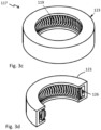
- Figure 3c is a perspective view of a cleaning arrangement 117 which cleaning arrangement comprises the coil spring 119 as shown in Figure 3a .
- Figure 3d is a cut through the cleaning arrangement 117 as shown in Figure 3c .
- the coil springs 119 as shown in Figure 3a and 3b could as well, in another example, be used as cleaning arrangement on its own, i.e. without a holder 123 as shown in Figure 3c .
- the cleaning arrangement 117 comprises at least one coil spring 119 which is provided over substantially the whole circumference of the sleeve 8 when the cleaning arrangement is provided in a liquid treatment system 2.
- the at least one coil spring 119 can be a garter spring 119 as shown in Figures 3a-3d but can also be a coil spring 219 which is bent to a circular shape which is shown in Figures 4a-b .
- the garter spring 119 can for example be a canted garter spring as shown in Figure 3a or a rectangular garter spring as shown in Figure 3b .
- the canted shape and the rectangular shape of these garter springs 119 will prevent the springs from rotating when sliding along the sleeve 8. Prevention of rotation will improve cleaning efficiency.
- the at least one coil spring (garter spring 119 in Figures 3 and bent coil spring 219 in Figures 4 ) is provided stretched wrapping around the sleeve 8 of the liquid treatment system 2 when the cleaning arrangement 117, 217 is provided in a liquid treatment system 2 such that the spring force of the at least one coil spring 119; 219 will press the coil spring towards the sleeve 8.
- a conform force is provided from the coil spring over the circumference of the sleeve 8.
- the cleaning arrangement 117 as shown in Figure 3c further comprises a ring shaped holder 123 which is provided for encircling the sleeve 8 and to be movable along the sleeve 8 when the cleaning arrangement 117 is provided in a liquid treatment system 2.
- Said holder 123 is enclosing an outer surface of the at least one coil spring 119.
- An inner surface of the coil spring 119 is abutting against the sleeve 8.
- the ring shaped holder 123 is not provided for pressing the coil spring towards the outer surface 10 of the sleeve 8. There may instead be a free space 126 between the outer surface of the at least one coil spring 119 and the ring shaped holder 123.
- the holder is mainly provided for allowing an axial force to be transferred to the coil spring 119 for moving the coil spring along the length of the sleeve 8 and thereby clean the outer surface 10 of the sleeve 8 by the action of the coil spring 119 towards the outer surface.
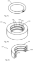
- Figure 4a shows a coil spring 219 which can be used in a cleaning arrangement 217.
- Figure 4b is a perspective view of a cleaning arrangement 217 which cleaning arrangement 217 comprises the coil spring 219 as shown in Figure 4a.
- Figure 4c is a cut through the cleaning arrangement as shown in Figure 4b .
- the cleaning arrangement 217 as shown in Figure 4b comprises two coil springs 219 as shown in Figure 4a .
- This coil spring 219 has been bent to a circular shape.
- the cleaning arrangement 217 of this example comprises a ring shaped holder 223 which holds two coil springs 219.
- the holder 223 comprises two internal grooves 225a, 225b for holding the two coil springs 219.
- the number of coil springs 219 and internal grooves could however also be another than two.
- the coil springs 219 are slightly stretched to be slid over the sleeve 8 when the cleaning arrangement 217 should be used in a liquid treatment system 2.
- the holder 223 is only holding the coil springs 219 in correct relative position and allows transferring of an axial movement to the coil springs 219 for cleaning the whole length of the sleeve 8.
- two pins 231a, 231b are used for preventing rotation of the coil springs 219.
- the pins 231a, 231b are provided in the holder 223 and are protruding into the coil spring ends 219 for keeping them in the same position in relation to the holder 223.
- the pins 231a, 231b can also be called rotation stop member 231a, 231b and can be provided in the holder for preventing rotation of the coil springs.
Landscapes
- Health & Medical Sciences (AREA)
- Toxicology (AREA)
- Life Sciences & Earth Sciences (AREA)
- Hydrology & Water Resources (AREA)
- Engineering & Computer Science (AREA)
- Environmental & Geological Engineering (AREA)
- Water Supply & Treatment (AREA)
- Chemical & Material Sciences (AREA)
- Organic Chemistry (AREA)
- Physical Water Treatments (AREA)
- Cleaning By Liquid Or Steam (AREA)
Claims (6)
- Agencement de nettoyage (17) configuré pour être utilisé dans un système de traitement de liquide (2), oùledit système de traitement de liquide comprend au moins une lampe (6) de traitement par lumière ultraviolette (UV) agencée à l'intérieur d'un manchon (8) protecteur allongé transparent aux UV fourni le long d'un axe longitudinal central A, ledit manchon (8) présentant une surface externe (10) et une forme essentiellement circulaire en coupe transversale et un réacteur (12) configuré pour recevoir ledit manchon (8), moyennant quoi une chambre de traitement de liquide (4) pour recevoir un liquide à traiter est fournie entre une surface interne (14) du réacteur (12) et la surface externe (10) du manchon (8), caractérisé en ce que ledit agencement de nettoyage comprend :- au moins deux ressorts hélicoïdaux (19) qui sont fournis dans l'agencement de nettoyage de telle sorte qu'ils seront enroulés autour d'au moins une partie d'une circonférence d'un manchon (8) d'un système de traitement de liquide (2) quand l'agencement de nettoyage (17) est fourni dans un système de traitement de liquide (2) et de telle sorte qu'une force de ressort des au moins deux ressorts hélicoïdaux (19) pressera les ressorts hélicoïdaux vers le manchon (8), dans lequel ledit agencement de nettoyage (17) est configuré pour être déplacé le long du manchon (8) et les ressorts hélicoïdaux nettoieront la surface extérieure (10) du manchon (8),dans lequel lesdits au moins deux ressorts hélicoïdaux (19) sont montés dans un support (23) de l'agencement de nettoyage de telle sorte que les ressorts hélicoïdaux s'enroulent ensemble sur essentiellement toute la circonférence d'un manchon d'un système de traitement de liquide (2) quand l'agencement de nettoyage (17) est fourni dans un système de traitement de liquide (2),dans lequel ledit support (23) de l'agencement de nettoyage (17) comprend une première partie de fixation (31a) de ressort hélicoïdal en forme d'anneau et une deuxième partie de fixation (31b) de ressort hélicoïdal en forme d'anneau qui sont reliées l'une à l'autre de telle sorte qu'elles sont fournies à distance l'une de l'autre, dans lequel les première et deuxième parties de fixation (31a, 31b) de ressort hélicoïdal sont configurées pour encercler un manchon (8) d'un système de traitement de liquide (2) quand l'agencement de nettoyage (17) est fourni dans un système de traitement de liquide (2) et configurées pour être mobiles le long du manchon et dans lequel une première extrémité (19a) de chaque ressort hélicoïdal (19) de l'agencement de nettoyage (17) est fixée à la première partie de fixation (31a) de ressort hélicoïdal et une deuxième extrémité (19b) de chaque ressort hélicoïdal (19) est fixée à la deuxième partie de fixation (31b) de ressort hélicoïdal de telle sorte que chaque ressort hélicoïdal (19) s'enroulera autour d'une partie de la circonférence du manchon (8) quand l'agencement de nettoyage (17) est fourni dans un système de traitement de liquide (2),dans lequel les ressorts hélicoïdaux (19) ne sont pas reliés par le trajet le plus court entre les première et deuxième parties de fixation (31a, 31b) de ressort hélicoïdal, mais sont plutôt montés en diagonale selon un schéma de rotation dans le support (23).
- Agencement de nettoyage selon la revendication 1, dans lequel les au moins deux ressorts hélicoïdaux sont des ressorts hélicoïdaux inclinés ou des ressorts hélicoïdaux rectangulaires.
- Agencement de nettoyage selon l'une quelconque des revendications précédentes, dans lequel les au moins deux ressorts hélicoïdaux sont en acier inoxydable ou en alliage de nickel.
- Agencement de nettoyage selon l'une quelconque des revendications précédentes, dans lequel ledit agencement de nettoyage (17) comprend au moins quatre ressorts hélicoïdaux (19), au moins cinq ressorts hélicoïdaux (19) ou au moins six ressorts hélicoïdaux (19).
- Agencement de nettoyage selon l'une quelconque des revendications précédentes, dans lequel les ressorts hélicoïdaux (19) sont étirés quand ils sont montés dans le support (23).
- Système de traitement de liquide (2) comprenant :- au moins une lampe (6) de traitement par lumière ultraviolette (UV) agencée à l'intérieur d'un manchon (8) protecteur allongé transparent aux UV fourni le long d'un axe longitudinal central A, ledit manchon (8) présentant une surface externe (10) et une forme essentiellement circulaire en coupe transversale ; et- un réacteur (12) configuré pour recevoir ledit manchon (8), moyennant quoi une chambre de traitement de liquide (4) pour recevoir un liquide à traiter est fournie entre une surface interne (14) du réacteur (12) et la surface externe (10) du manchon (8) ; dans lequel ledit système de traitement de liquide (2) comprend en outre au moins un agencement de nettoyage (17) selon l'une quelconque des revendications précédentes.
Applications Claiming Priority (2)
| Application Number | Priority Date | Filing Date | Title |
|---|---|---|---|
| SE2050120A SE544296C2 (en) | 2020-02-06 | 2020-02-06 | Cleaning arrangement for a liquid treatment system |
| PCT/SE2021/050023 WO2021158156A1 (fr) | 2020-02-06 | 2021-01-18 | Agencement de nettoyage pour un système de traitement de liquide |
Publications (4)
| Publication Number | Publication Date |
|---|---|
| EP4100369A1 EP4100369A1 (fr) | 2022-12-14 |
| EP4100369A4 EP4100369A4 (fr) | 2023-10-04 |
| EP4100369C0 EP4100369C0 (fr) | 2024-09-25 |
| EP4100369B1 true EP4100369B1 (fr) | 2024-09-25 |
Family
ID=77200794
Family Applications (1)
| Application Number | Title | Priority Date | Filing Date |
|---|---|---|---|
| EP21751353.0A Active EP4100369B1 (fr) | 2020-02-06 | 2021-01-18 | Agencement de nettoyage pour un système de traitement de liquide |
Country Status (4)
| Country | Link |
|---|---|
| US (1) | US12240769B2 (fr) |
| EP (1) | EP4100369B1 (fr) |
| SE (1) | SE544296C2 (fr) |
| WO (1) | WO2021158156A1 (fr) |
Family Cites Families (16)
| Publication number | Priority date | Publication date | Assignee | Title |
|---|---|---|---|---|
| US5227140A (en) | 1990-04-13 | 1993-07-13 | Peroxidation Systems, Inc. | Modular self-cleaning oxidation chamber |
| US5834256A (en) | 1993-06-11 | 1998-11-10 | Cell Genesys, Inc. | Method for production of high titer virus and high efficiency retroviral mediated transduction of mammalian cells |
| US5501843A (en) | 1994-10-14 | 1996-03-26 | Vulcan Peroxidation Systems, Inc. | Wiper cartridge |
| US5528044A (en) * | 1995-04-28 | 1996-06-18 | Solar Kinetics, Inc. | Wiper assembly for ultraviolet-light reactor tubes |
| US5937266A (en) | 1996-03-08 | 1999-08-10 | Photoscience Japan Corporation | Light irradiating device employing light irradiating modules equipped with a cleaning mechanism |
| US5874740A (en) * | 1996-03-14 | 1999-02-23 | Photoscience Japan Corporation | Ultraviolet ray irradiation equipment having scraper rings fitted to light transmission tubes |
| USRE39522E1 (en) | 1996-03-14 | 2007-03-20 | Photoscience Japan Corporation | Ultraviolet ray irradiation equipment having scraper rings fitted to light transmission tubes |
| GB0213581D0 (en) * | 2002-06-13 | 2002-07-24 | Snowball Malcolm R | Fluid treatment apparatus |
| ES2285048T3 (es) | 2002-06-13 | 2007-11-16 | Malcolm Robert Snowball | Aparato para tratamiento de fluidos. |
| US7159264B2 (en) | 2004-12-10 | 2007-01-09 | Calgon Carbon Corporation | Scraper for cleaning tubular members |
| GB2425121A (en) | 2005-04-13 | 2006-10-18 | Malcolm Robert Snowball | Fluid disinfection apparatus and system |
| KR100860745B1 (ko) | 2007-03-14 | 2008-09-29 | (주)선일 엔바이로 | 자외선 소독설비 |
| KR100971177B1 (ko) * | 2010-04-07 | 2010-07-20 | (주)유브이플러스 | 자외선 투과율이 낮은 유체를 살균하는데 적합한 자외선 유체 살균기 |
| US20150335911A1 (en) * | 2014-05-20 | 2015-11-26 | Rogers Sciences, Inc. | Light emitting system for wound care |
| SE1650595A1 (en) * | 2016-05-03 | 2017-10-24 | Wallenius Water Ab | A UV light liquid treatment system |
| SE540414C2 (en) | 2017-02-17 | 2018-09-11 | Wallenius Water Innovation Ab | A liquid treatment system including a cleaning arrangement |
-
2020
- 2020-02-06 SE SE2050120A patent/SE544296C2/en unknown
-
2021
- 2021-01-18 US US17/790,855 patent/US12240769B2/en active Active
- 2021-01-18 EP EP21751353.0A patent/EP4100369B1/fr active Active
- 2021-01-18 WO PCT/SE2021/050023 patent/WO2021158156A1/fr not_active Ceased
Also Published As
| Publication number | Publication date |
|---|---|
| EP4100369A4 (fr) | 2023-10-04 |
| EP4100369C0 (fr) | 2024-09-25 |
| SE2050120A1 (en) | 2021-08-07 |
| SE544296C2 (en) | 2022-03-29 |
| US12240769B2 (en) | 2025-03-04 |
| WO2021158156A1 (fr) | 2021-08-12 |
| US20230025794A1 (en) | 2023-01-26 |
| EP4100369A1 (fr) | 2022-12-14 |
Similar Documents
| Publication | Publication Date | Title |
|---|---|---|
| JP4624634B2 (ja) | 管状部材のスクレーパ | |
| KR100216492B1 (ko) | 와이퍼 카트리지 | |
| EP3583071B1 (fr) | Système de traitement de liquide | |
| JP4937133B2 (ja) | 管状部材掃除用スクレーパ | |
| EP3583070B1 (fr) | Système de traitement de liquide | |
| US12240769B2 (en) | Cleaning arrangement for a liquid treatment system | |
| EP3452410B1 (fr) | Système de traitement de liquide comprenant une lampe ultraviolette à lumière uv |
Legal Events
| Date | Code | Title | Description |
|---|---|---|---|
| STAA | Information on the status of an ep patent application or granted ep patent |
Free format text: STATUS: THE INTERNATIONAL PUBLICATION HAS BEEN MADE |
|
| PUAI | Public reference made under article 153(3) epc to a published international application that has entered the european phase |
Free format text: ORIGINAL CODE: 0009012 |
|
| STAA | Information on the status of an ep patent application or granted ep patent |
Free format text: STATUS: REQUEST FOR EXAMINATION WAS MADE |
|
| 17P | Request for examination filed |
Effective date: 20220628 |
|
| AK | Designated contracting states |
Kind code of ref document: A1 Designated state(s): AL AT BE BG CH CY CZ DE DK EE ES FI FR GB GR HR HU IE IS IT LI LT LU LV MC MK MT NL NO PL PT RO RS SE SI SK SM TR |
|
| DAV | Request for validation of the european patent (deleted) | ||
| DAX | Request for extension of the european patent (deleted) | ||
| A4 | Supplementary search report drawn up and despatched |
Effective date: 20230831 |
|
| RIC1 | Information provided on ipc code assigned before grant |
Ipc: C02F 1/32 20060101AFI20230825BHEP |
|
| RAP3 | Party data changed (applicant data changed or rights of an application transferred) |
Owner name: WALLENIUS WATER INNOVATION AB |
|
| GRAP | Despatch of communication of intention to grant a patent |
Free format text: ORIGINAL CODE: EPIDOSNIGR1 |
|
| STAA | Information on the status of an ep patent application or granted ep patent |
Free format text: STATUS: GRANT OF PATENT IS INTENDED |
|
| INTG | Intention to grant announced |
Effective date: 20240510 |
|
| GRAS | Grant fee paid |
Free format text: ORIGINAL CODE: EPIDOSNIGR3 |
|
| GRAA | (expected) grant |
Free format text: ORIGINAL CODE: 0009210 |
|
| STAA | Information on the status of an ep patent application or granted ep patent |
Free format text: STATUS: THE PATENT HAS BEEN GRANTED |
|
| AK | Designated contracting states |
Kind code of ref document: B1 Designated state(s): AL AT BE BG CH CY CZ DE DK EE ES FI FR GB GR HR HU IE IS IT LI LT LU LV MC MK MT NL NO PL PT RO RS SE SI SK SM TR |
|
| REG | Reference to a national code |
Ref country code: GB Ref legal event code: FG4D |
|
| REG | Reference to a national code |
Ref country code: CH Ref legal event code: EP |
|
| REG | Reference to a national code |
Ref country code: DE Ref legal event code: R096 Ref document number: 602021019351 Country of ref document: DE |
|
| REG | Reference to a national code |
Ref country code: IE Ref legal event code: FG4D |
|
| U01 | Request for unitary effect filed |
Effective date: 20240930 |
|
| U07 | Unitary effect registered |
Designated state(s): AT BE BG DE DK EE FI FR IT LT LU LV MT NL PT RO SE SI Effective date: 20241024 |
|
| PG25 | Lapsed in a contracting state [announced via postgrant information from national office to epo] |
Ref country code: GR Free format text: LAPSE BECAUSE OF FAILURE TO SUBMIT A TRANSLATION OF THE DESCRIPTION OR TO PAY THE FEE WITHIN THE PRESCRIBED TIME-LIMIT Effective date: 20241226 |
|
| PG25 | Lapsed in a contracting state [announced via postgrant information from national office to epo] |
Ref country code: RS Free format text: LAPSE BECAUSE OF FAILURE TO SUBMIT A TRANSLATION OF THE DESCRIPTION OR TO PAY THE FEE WITHIN THE PRESCRIBED TIME-LIMIT Effective date: 20241225 |
|
| PG25 | Lapsed in a contracting state [announced via postgrant information from national office to epo] |
Ref country code: RS Free format text: LAPSE BECAUSE OF FAILURE TO SUBMIT A TRANSLATION OF THE DESCRIPTION OR TO PAY THE FEE WITHIN THE PRESCRIBED TIME-LIMIT Effective date: 20241225 Ref country code: GR Free format text: LAPSE BECAUSE OF FAILURE TO SUBMIT A TRANSLATION OF THE DESCRIPTION OR TO PAY THE FEE WITHIN THE PRESCRIBED TIME-LIMIT Effective date: 20241226 |
|
| U20 | Renewal fee for the european patent with unitary effect paid |
Year of fee payment: 5 Effective date: 20250115 |
|
| PG25 | Lapsed in a contracting state [announced via postgrant information from national office to epo] |
Ref country code: IS Free format text: LAPSE BECAUSE OF FAILURE TO SUBMIT A TRANSLATION OF THE DESCRIPTION OR TO PAY THE FEE WITHIN THE PRESCRIBED TIME-LIMIT Effective date: 20250125 |
|
| PG25 | Lapsed in a contracting state [announced via postgrant information from national office to epo] |
Ref country code: SM Free format text: LAPSE BECAUSE OF FAILURE TO SUBMIT A TRANSLATION OF THE DESCRIPTION OR TO PAY THE FEE WITHIN THE PRESCRIBED TIME-LIMIT Effective date: 20240925 |
|
| PG25 | Lapsed in a contracting state [announced via postgrant information from national office to epo] |
Ref country code: ES Free format text: LAPSE BECAUSE OF FAILURE TO SUBMIT A TRANSLATION OF THE DESCRIPTION OR TO PAY THE FEE WITHIN THE PRESCRIBED TIME-LIMIT Effective date: 20240925 |
|
| PG25 | Lapsed in a contracting state [announced via postgrant information from national office to epo] |
Ref country code: PL Free format text: LAPSE BECAUSE OF FAILURE TO SUBMIT A TRANSLATION OF THE DESCRIPTION OR TO PAY THE FEE WITHIN THE PRESCRIBED TIME-LIMIT Effective date: 20240925 Ref country code: CZ Free format text: LAPSE BECAUSE OF FAILURE TO SUBMIT A TRANSLATION OF THE DESCRIPTION OR TO PAY THE FEE WITHIN THE PRESCRIBED TIME-LIMIT Effective date: 20240925 |
|
| PG25 | Lapsed in a contracting state [announced via postgrant information from national office to epo] |
Ref country code: SK Free format text: LAPSE BECAUSE OF FAILURE TO SUBMIT A TRANSLATION OF THE DESCRIPTION OR TO PAY THE FEE WITHIN THE PRESCRIBED TIME-LIMIT Effective date: 20240925 |
|
| PLBE | No opposition filed within time limit |
Free format text: ORIGINAL CODE: 0009261 |
|
| STAA | Information on the status of an ep patent application or granted ep patent |
Free format text: STATUS: NO OPPOSITION FILED WITHIN TIME LIMIT |
|
| REG | Reference to a national code |
Ref country code: CH Ref legal event code: PL |
|
| 26N | No opposition filed |
Effective date: 20250626 |
|
| PG25 | Lapsed in a contracting state [announced via postgrant information from national office to epo] |
Ref country code: MC Free format text: LAPSE BECAUSE OF FAILURE TO SUBMIT A TRANSLATION OF THE DESCRIPTION OR TO PAY THE FEE WITHIN THE PRESCRIBED TIME-LIMIT Effective date: 20240925 |
|
| GBPC | Gb: european patent ceased through non-payment of renewal fee |
Effective date: 20250118 |
|
| PG25 | Lapsed in a contracting state [announced via postgrant information from national office to epo] |
Ref country code: GB Free format text: LAPSE BECAUSE OF NON-PAYMENT OF DUE FEES Effective date: 20250118 |
|
| PG25 | Lapsed in a contracting state [announced via postgrant information from national office to epo] |
Ref country code: CH Free format text: LAPSE BECAUSE OF NON-PAYMENT OF DUE FEES Effective date: 20250131 |
|
| PG25 | Lapsed in a contracting state [announced via postgrant information from national office to epo] |
Ref country code: HR Free format text: LAPSE BECAUSE OF FAILURE TO SUBMIT A TRANSLATION OF THE DESCRIPTION OR TO PAY THE FEE WITHIN THE PRESCRIBED TIME-LIMIT Effective date: 20240925 |
|
| PG25 | Lapsed in a contracting state [announced via postgrant information from national office to epo] |
Ref country code: IE Free format text: LAPSE BECAUSE OF NON-PAYMENT OF DUE FEES Effective date: 20250118 |
|
| U20 | Renewal fee for the european patent with unitary effect paid |
Year of fee payment: 6 Effective date: 20260116 |
|
| PGFP | Annual fee paid to national office [announced via postgrant information from national office to epo] |
Ref country code: NO Payment date: 20260126 Year of fee payment: 6 |