EP4100357B1 - Device for opening a bottle of wine or the like with a hot clamp - Google Patents
Device for opening a bottle of wine or the like with a hot clamp Download PDFInfo
- Publication number
- EP4100357B1 EP4100357B1 EP21707350.1A EP21707350A EP4100357B1 EP 4100357 B1 EP4100357 B1 EP 4100357B1 EP 21707350 A EP21707350 A EP 21707350A EP 4100357 B1 EP4100357 B1 EP 4100357B1
- Authority
- EP
- European Patent Office
- Prior art keywords
- bracket
- casing
- clamp
- base
- heating means
- Prior art date
- Legal status (The legal status is an assumption and is not a legal conclusion. Google has not performed a legal analysis and makes no representation as to the accuracy of the status listed.)
- Active
Links
- 235000014101 wine Nutrition 0.000 title claims description 20
- 238000010438 heat treatment Methods 0.000 claims description 29
- 238000005485 electric heating Methods 0.000 claims description 3
- 230000000284 resting effect Effects 0.000 claims 1
- 239000007799 cork Substances 0.000 description 11
- 238000000034 method Methods 0.000 description 7
- 239000002184 metal Substances 0.000 description 5
- 238000009825 accumulation Methods 0.000 description 3
- 235000009508 confectionery Nutrition 0.000 description 3
- 238000001816 cooling Methods 0.000 description 2
- 230000006866 deterioration Effects 0.000 description 2
- 230000035939 shock Effects 0.000 description 2
- 239000004575 stone Substances 0.000 description 2
- XLYOFNOQVPJJNP-UHFFFAOYSA-N water Substances O XLYOFNOQVPJJNP-UHFFFAOYSA-N 0.000 description 2
- LFQSCWFLJHTTHZ-UHFFFAOYSA-N Ethanol Chemical compound CCO LFQSCWFLJHTTHZ-UHFFFAOYSA-N 0.000 description 1
- 230000015556 catabolic process Effects 0.000 description 1
- 239000000919 ceramic Substances 0.000 description 1
- 229910010293 ceramic material Inorganic materials 0.000 description 1
- 229910052878 cordierite Inorganic materials 0.000 description 1
- 238000006731 degradation reaction Methods 0.000 description 1
- JSKIRARMQDRGJZ-UHFFFAOYSA-N dimagnesium dioxido-bis[(1-oxido-3-oxo-2,4,6,8,9-pentaoxa-1,3-disila-5,7-dialuminabicyclo[3.3.1]nonan-7-yl)oxy]silane Chemical compound [Mg++].[Mg++].[O-][Si]([O-])(O[Al]1O[Al]2O[Si](=O)O[Si]([O-])(O1)O2)O[Al]1O[Al]2O[Si](=O)O[Si]([O-])(O1)O2 JSKIRARMQDRGJZ-UHFFFAOYSA-N 0.000 description 1
- 239000004744 fabric Substances 0.000 description 1
- 239000011521 glass Substances 0.000 description 1
- 239000010438 granite Substances 0.000 description 1
- 229920003052 natural elastomer Polymers 0.000 description 1
- 229920001194 natural rubber Polymers 0.000 description 1
- 229920001296 polysiloxane Polymers 0.000 description 1
- 239000000843 powder Substances 0.000 description 1
- 235000020095 red wine Nutrition 0.000 description 1
- 239000011343 solid material Substances 0.000 description 1
- 229920003051 synthetic elastomer Polymers 0.000 description 1
- 235000020097 white wine Nutrition 0.000 description 1
Images


Classifications
-
- B—PERFORMING OPERATIONS; TRANSPORTING
- B67—OPENING, CLOSING OR CLEANING BOTTLES, JARS OR SIMILAR CONTAINERS; LIQUID HANDLING
- B67B—APPLYING CLOSURE MEMBERS TO BOTTLES JARS, OR SIMILAR CONTAINERS; OPENING CLOSED CONTAINERS
- B67B7/00—Hand- or power-operated devices for opening closed containers
- B67B7/02—Hand- or power-operated devices for opening closed containers for removing stoppers
-
- B—PERFORMING OPERATIONS; TRANSPORTING
- B67—OPENING, CLOSING OR CLEANING BOTTLES, JARS OR SIMILAR CONTAINERS; LIQUID HANDLING
- B67B—APPLYING CLOSURE MEMBERS TO BOTTLES JARS, OR SIMILAR CONTAINERS; OPENING CLOSED CONTAINERS
- B67B7/00—Hand- or power-operated devices for opening closed containers
- B67B7/92—Hand- or power-operated devices for opening closed containers by breaking, e.g. for ampoules
Definitions
- the present invention relates to the field of wine and more particularly a device for opening bottles of natural sweet wines such as port for example.
- the cork stoppers closing port bottles disintegrate over time due to the alcohol level and the sugar content of the port in particular, the lower part of the cork stopper generally being the most degraded due to the fact that it is partly in direct contact with the port.
- the process consists of heating the jaws of the port tongs on the embers of a fireplace or the like then positioning the white-hot jaws around the neck of the port bottle under the lower end of the cork, then removing the jaws hot water from the neck and place a cloth soaked in cold water on the neck in the area heated by the jaws.
- the thermal shock causes the glass to break and the upper end of the neck of the bottle can be removed with the cork and the port can then be served after decanting if necessary.
- One of the aims of the invention is therefore to remedy these drawbacks by proposing a device for opening a bottle of wine with hot pliers of a simple and inexpensive design, easy to use and providing good security. for the user.
- a device for opening a bottle of wine comprising a clamp consisting of two arms articulated around an axis, each arm comprising at a first end a handle or a ring and at its opposite end a jaw of semi-annular or semi-cylindrical shape, the radius of curvature of each jaw being substantially equal to the radius of curvature of the wine bottle; said device is remarkable in that it comprises at least one base, heating means positioned on said base and a bracket secured to the base and comprising means for retaining the pliers such that the jaws of the latter extend to the right of the heating means.
- said bracket comprises a vertical lower part, i.e. extending substantially perpendicular to said base, and an inclined upper part.
- the upper part of the stem forms an angle of between 100° and 130° with the lower part of said stem and, preferably, the upper part of the stem forms an angle of 115° with the lower part of said stem .
- the distal end of the stem ie the upper end of the upper part of said stem, is folded upwards at an angle of approximately 90° to form a so-called retaining tab provided with at least one slot capable of receiving the arms of the pliers.
- the upper part of the stem includes at least one cradle in which the arms of the clamp are supported.
- the heating means consist of at least one electrical heating resistance coupled to a thermostat or a rheostat, said electrical heating resistance being in contact with the jaws of the pliers when the latter is supported by the bracket.
- the heating means consist of at least one gas bottle provided with a burner and a gas flow adjustment dial, said gas bottle extending into a casing whose lower end is open and rests on the base and the upper end of which is provided with an upper cover provided with an opening for the passage of the burner.
- the casing has a cylindrical shape.
- the upper cover is made up of two half-discs, each half-disc comprising a semi-circular recess in the central part of the rectilinear edge and a curved tab secured to the curvilinear edge and capable of bearing on the upper edge of the housing.
- the casing comprises, in its lower part, a crown secured to the interior wall of said casing on which a circular plate rests, said plate being able to receive the gas bottle .
- the device comprises a remote control means of the gas flow adjustment wheel, said remote control means consisting of a rod extending through a hole made in the casing and comprising at its free ends a wheel and a flat head respectively, said flat head being able to cooperate with a slot made in the gas flow adjustment wheel.
- the device according to the invention is particularly suitable for opening old port bottles whose cork is damaged; however, it is obvious that the device according to the invention could also be used not only for opening bottles of all types of natural sweet wines which encounters the same type of degradation of their cork stoppers but also for the opening of any type of wine bottle whether the cork is degraded or not without departing from the scope of the invention.
- Said base 6 consists of a substantially square horizontal metal plate provided with four feet 9 positioned at the four corners of the metal plate on its underside.
- Said feet 9 may advantageously consist of feet made of silicone or synthetic or natural elastomer in order to prevent said base 6 from sliding on the support, such as a table for example, on which it will be positioned.
- the pliers 1 could have a different shape such as a scissor shape, i.e. with rings in place of the handles 4 and/or with semi-cylindrical jaws 5 in place of the semi-cylindrical jaws 4 -annular for example without departing from the scope of the invention.
- said bracket 8 comprises a vertical lower part 8a, ie extending substantially perpendicular to said base 6, and an inclined upper part 8b.
- Said bracket 8 is, for example, obtained in a metal bar whose lower end is welded in the central part of one of the edges of the base 6 and whose middle part is folded to form the lower parts 8a and upper 8b.
- Said upper part 8b of the bracket 8 forms an angle of between 100° and 130° with the lower part 8a of said bracket 8, and, preferably, an angle of 115° with the lower part 8a of said bracket 8.
- the distal end of the bracket 8, ie the upper end of the upper part 8b of said bracket 8, is folded upwards at an angle of approximately 90° to form a so-called retaining tab 10 provided with at less a slot 11 capable of receiving the arms 2 of the clamp 1, the handles 4 of the clamp 4 bearing on the upper face of the tab 10.
- said upper part 8b of the bracket 8 comprises at least one cradle 12 in which the arms 2 of the clamp 1 are supported.
- the heating means 7 consist of at least one gas bottle 13 provided with a burner 14 and a wheel 15 for adjusting the gas flow, said gas bottle 13 extending into a casing 16 of which the the lower end is open and rests on the base 6 and the upper end of which is provided with an upper cover 17 provided with an opening 18 for the passage of the burner 14.
- the casing 16 has a cylindrical shape; however, it goes without saying that it can have any shape as long as it is capable of receiving a gas bottle, without departing from the scope of the invention.
- the casing 16 comprises, in its lower part, a crown 19 secured to the interior wall of said casing 16 on which rests a removable circular plate 20, said plate 20 being capable of receiving the gas bottle 13.
- the casing 16 allows two different sizes of gas bottle 13 to be received.
- the plate 20 is removed and the gas bottle rests directly on the base 6 and, for the smallest size of gas bottle 13, the plate 20 is positioned on the crown 19 and the gas bottle rests on said plate 20.
- the device according to the invention comprises a remote control means 21 of the wheel 15 for adjusting the gas flow, said remote control means 21 consisting of a rod 22 extending through a hole 23 made in the casing 16 and comprising at its free ends a wheel 24 and a flat head 25 respectively, said flat head 25 being able to cooperate with a slot 26 made in the wheel 15 for adjusting the gas flow.
- the device comprises in the same manner as previously a clamp 1 consisting of two arms 2 articulated around an axis 3, each arm 2 comprising at a first end a handle 4 and at its opposite end a jaw 5 of semi-annular shape , the radius of curvature of each jaw 5 being substantially equal to the radius of curvature of the wine bottle, not shown in the figures, a base 6, heating means 7 positioned on said base 6 and a bracket 8 integral with said base 6 and comprising means for retaining the clamp 1 such that the jaws 5 of said clamp 1 extend to the right of the heating means 7.
- Said base 6 consists of a substantially square horizontal metal plate provided with four feet 9 positioned at the four corners of the metal plate on its underside.
- said bracket 8 comprises a vertical lower part 8a and an inclined upper part 8b. Its lower end is welded in the central part of one of the edges of the base 6 and the middle part is folded to form the lower parts 8a and upper 8b. Said upper part 8b of the bracket 8 forms an angle of between 100° and 130° with the lower part 8a of said bracket 8, and, preferably, an angle of 115°.
- the distal end of the bracket 8, i.e. the upper end of the upper part 8b of said bracket 8 is folded upwards at an angle of approximately 90° to form a so-called retaining tab 10 provided with at least one bayonet slot 11 capable of receiving the arms 2 of the pliers 1, the handles 4 of the pliers 4 bearing on the upper face of the tab 10.
- said upper part 8b of the bracket 8 comprises at least one cradle 12 in which the arms 2 of the clamp 1 are supported.
- the heating means 7 consist of at least one gas bottle 13 provided with a burner 14 and a wheel 15 for adjusting the gas flow, said gas bottle 13 extending into a cylindrical casing 16 of which the lower end is open and rests on the base 6 and the upper end of which is provided with an upper cover 17 provided with an opening 18 for the passage of the burner 14.
- the casing 16 also comprises, in its lower part, a crown 19 secured to the interior wall of said casing 16 on which rests a removable circular plate 20, said plate 20 being capable of receiving the gas bottle 13.
- the casing 16 makes it possible to receive two different sizes of gas bottle 13.
- the device according to the invention also comprises a remote control means 21 of the wheel 15 for adjusting the gas flow, as shown on the figures 3 to 5 , said remote control means 21 consisting of a rod 22 extending through a hole 23 made in the casing 16 and comprising at its free ends a wheel 24 and a flat head 25 respectively, said flat head 25 being capable of cooperate with a slot 26 made in the wheel 15 for adjusting the gas flow.
- the device differs from that described previously by the fact that the upper cover 17 is made up of two half-discs 17a, 17ab, each half-disc 17a, 17b comprising a semicircular recess 18a and 18b respectively in the central part of the rectilinear edge and a curved tab 19a and 19b respectively secured to the curvilinear edge and capable of bearing on the upper edge of the casing 16.
- the device according to the invention comprises heating means consisting of at least one electrical heating resistance coupled to a thermostat or a rheostat, said electrical resistance heating being in contact, or extending close to, the jaws of the pliers when the latter is supported by the bracket.
- the electric heating resistance may be covered with a ceramic material and have a circular shape.
- the heating means may comprise two electrical heating resistors covered with ceramic and articulated around an axis so as to pivot from an open position where the electrical heating resistors extend on either side of the jaws of the pliers to a closed position where the electrical heating resistors cap the jaws of the pliers.
- the device according to the invention comprises a second clamp 27 consisting of two arms 28 articulated around an axis 29, each arm 28 comprising at a first end a ring 30 and at its opposite end a jaw 31 of semi-annular shape, the radius of curvature of each jaw 31 being substantially equal to the radius of curvature of the neck of the wine bottle.
- the concave face of each jaw 31 comprises one or more thermal accumulation elements 32. These thermal accumulation elements 32 can be obtained in stone such as sandstone or granite for example.
- these thermal storage elements are obtained in at least one solid material having a thermal conductivity greater than or equal to 5 Wm-1.K-1 and a density greater than or equal to 2000 kg/m3.
- the thermal accumulation elements 32 are obtained in a single-piece natural stone or in powder form, compacted or not.
- the thermal storage elements 32 are obtained in steatite and/or cordierite and/or feolite. Said clamp 1 is thus placed in a tray of ice or in a refrigerator or freezer before being used.
Description
La présente invention concerne le domaine du vin et plus particulièrement un dispositif pour l'ouverture des bouteilles de vins doux naturels tels que le porto par exemple.The present invention relates to the field of wine and more particularly a device for opening bottles of natural sweet wines such as port for example.
Dans le domaine du vin, il est bien connu qu'il est particulièrement difficile d'ouvrir une bouteille d'un vieux porto au moyen d'un tire-bouchon traditionnel en raison de la détérioration de son bouchon en liège. En effet, les bouchons en liège fermant les bouteilles de porto se désagrègent au cours du temps en raison du taux d'alcool et de la teneur en sucre du porto notamment, la partie basse du bouchon en liège étant généralement la plus dégradée du fait qu'elle est en partie en contact direct avec le porto.In the wine industry, it is well known that it is particularly difficult to open a bottle of old port using a traditional corkscrew due to the deterioration of its cork. In fact, the cork stoppers closing port bottles disintegrate over time due to the alcohol level and the sugar content of the port in particular, the lower part of the cork stopper generally being the most degraded due to the fact that it is partly in direct contact with the port.
Ainsi, plus le porto est ancien et plus le bouchon est dégradé de sorte qu'il devient impossible de retirer le bouchon au moyen d'un tire-bouchon.Thus, the older the port, the more degraded the cork is so that it becomes impossible to remove the cork using a corkscrew.
On notera que ce problème de détérioration du bouchon au cours du temps intervient également avec d'autres vins, qu'il s'agisse de vin rouge ou de vin blanc.Note that this problem of deterioration of the cork over time also occurs with other wines, whether red wine or white wine.
Afin de remédier à cet inconvénient, il est bien connu d'ouvrir ces bouteilles de vieux porto selon une technique dite de la pince chaude. Cette technique consiste à utiliser une pince dite à porto constituée de deux bras articulés autour d'un axe, chaque bras comprenant à une première extrémité une poignée et à son extrémité opposée un mors de forme hémi-annulaire.In order to remedy this drawback, it is well known to open these bottles of old port using a technique known as hot pliers. This technique consists of using so-called port pliers made up of two arms articulated around an axis, each arm comprising at one end a handle and at its opposite end a semi-annular shaped jaw.
Le procédé consiste à chauffer les mors de la pince à porto sur les braises d'un foyer ou similaire puis à positionner les mors chauffés à blanc autour du goulot de la bouteille de porto sous l'extrémité inférieure du bouchon, puis à retirer les mors chauds du goulot et apposer un chiffon imbiber d'eau froide sur le goulot au niveau de la zone chauffée par les mors. Le choc thermique procure la cassure du verre et l'extrémité supérieure du goulot de la bouteille peut être retiré avec le bouchon et le porto peut ensuite être servi après décantation si nécessaire.The process consists of heating the jaws of the port tongs on the embers of a fireplace or the like then positioning the white-hot jaws around the neck of the port bottle under the lower end of the cork, then removing the jaws hot water from the neck and place a cloth soaked in cold water on the neck in the area heated by the jaws. The thermal shock causes the glass to break and the upper end of the neck of the bottle can be removed with the cork and the port can then be served after decanting if necessary.
L'inconvénient de ce procédé est qu'il nécessite une certaine pratique de sorte qu'elle n'est pratiquée que par de rares sommeliers, généralement dans des restaurants.The downside of this process is that it requires some practice so it is only done by rare sommeliers, usually in restaurants.
Il existe donc un besoin de procurer un dispositif permettant la mise en oeuvre de ce procédé par des particuliers n'ayant pas de connaissance particulière dudit procédé de la pince chaude.There is therefore a need to provide a device allowing the implementation of this process by individuals who have no particular knowledge of said hot clamp process.
L'article intitulé "
L'un des buts de l'invention est donc de remédier à ces inconvénients en proposant un dispositif pour l'ouverture d'une bouteille de vin avec une pince chaude de conception simple et peu onéreuse, facile d'utilisation et procurant une bonne sécurité pour l'utilisateur.One of the aims of the invention is therefore to remedy these drawbacks by proposing a device for opening a bottle of wine with hot pliers of a simple and inexpensive design, easy to use and providing good security. for the user.
A cet effet, et conformément à l'invention, il est proposé un dispositif pour l'ouverture d'une bouteille de vin comprenant une pince constituée de deux bras articulés autour d'un axe, chaque bras comprenant à une première extrémité une poignée ou un anneau et à son extrémité opposée un mors de forme hémi-annulaire ou hémi-cylindrique, le rayon de courbure de chaque mors étant sensiblement égal au rayon de courbure de la bouteille de vin ; ledit dispositif est remarquable en ce qu'il comprend au moins un socle, des moyens de chauffage positionnés sur ledit socle et une potence solidaire du socle et comprenant des moyens de retenu de la pince de telle sorte que les mors de cette dernière s'étendent au droit des moyens de chauffage.For this purpose, and in accordance with the invention, a device is proposed for opening a bottle of wine comprising a clamp consisting of two arms articulated around an axis, each arm comprising at a first end a handle or a ring and at its opposite end a jaw of semi-annular or semi-cylindrical shape, the radius of curvature of each jaw being substantially equal to the radius of curvature of the wine bottle; said device is remarkable in that it comprises at least one base, heating means positioned on said base and a bracket secured to the base and comprising means for retaining the pliers such that the jaws of the latter extend to the right of the heating means.
De préférence, ladite potence comporte une partie inférieure verticale, i.e. s'étendant sensiblement perpendiculairement audit socle, et une partie supérieure inclinée.Preferably, said bracket comprises a vertical lower part, i.e. extending substantially perpendicular to said base, and an inclined upper part.
Par ailleurs, la partie supérieure de la potence forme un angle compris entre 100° et 130° avec la partie inférieure de ladite potence et, de préférence, la partie supérieure de la potence forme un angle de 115° avec la partie inférieure de ladite potence.Furthermore, the upper part of the stem forms an angle of between 100° and 130° with the lower part of said stem and, preferably, the upper part of the stem forms an angle of 115° with the lower part of said stem .
De plus, l'extrémité distale de la potence, i.e. l'extrémité supérieure de la partie supérieure de ladite potence, est repliée vers le haut suivant une angle d'environ 90° pour former une patte dite de retenue munie d'au moins une fente apte à recevoir les bras de la pince.In addition, the distal end of the stem, ie the upper end of the upper part of said stem, is folded upwards at an angle of approximately 90° to form a so-called retaining tab provided with at least one slot capable of receiving the arms of the pliers.
Afin d'assurer la stabilité de la pince, la partie supérieure de la potence comporte au moins un berceau dans lequel prend appui les bras de la pince.In order to ensure the stability of the clamp, the upper part of the stem includes at least one cradle in which the arms of the clamp are supported.
Selon une première variante d'exécution, les moyens de chauffage consistent en au moins une résistance électrique chauffante couplée à un thermostat ou un rhéostat, ladite résistance électrique chauffante étant au contact des mors de la pince lorsque cette dernière est supportée par la potence.According to a first variant of execution, the heating means consist of at least one electrical heating resistance coupled to a thermostat or a rheostat, said electrical heating resistance being in contact with the jaws of the pliers when the latter is supported by the bracket.
Selon une seconde variante d'exécution, les moyens de chauffage consistent en au moins une bouteille de gaz muni d'un brûleur et d'une molette de réglage du débit de gaz, ladite bouteille de gaz s'étendant dans un carter dont l'extrémité inférieure est ouverte et prend appui sur le socle et dont l'extrémité supérieure est muni d'un capot supérieur muni d'une ouverture pour le passage du brûleur.According to a second alternative embodiment, the heating means consist of at least one gas bottle provided with a burner and a gas flow adjustment dial, said gas bottle extending into a casing whose lower end is open and rests on the base and the upper end of which is provided with an upper cover provided with an opening for the passage of the burner.
De préférence, le carter présente une forme cylindrique.Preferably, the casing has a cylindrical shape.
Par ailleurs, selon une variante d'exécution, le capot supérieur est constitué de deux demi-disques, chaque demi-disque comprenant un évidement hémicirculaire dans la partie centrale du bord rectiligne et une patte recourbée solidaire du bord curviligne et apte à prendre appui sur le bord supérieur du carter.Furthermore, according to an alternative embodiment, the upper cover is made up of two half-discs, each half-disc comprising a semi-circular recess in the central part of the rectilinear edge and a curved tab secured to the curvilinear edge and capable of bearing on the upper edge of the housing.
Afin de permettre l'utilisation de différentes tailles de bouteille de gaz, le carter comporte, dans sa partie inférieure, une couronne solidaire de la paroi intérieure dudit carter sur laquelle prend appui un plateau circulaire, ledit plateau étant apte à recevoir la bouteille de gaz.In order to allow the use of different sizes of gas bottle, the casing comprises, in its lower part, a crown secured to the interior wall of said casing on which a circular plate rests, said plate being able to receive the gas bottle .
De plus, le dispositif comporte un moyen de commande déporté de la molette de réglage du débit de gaz, ledit moyen de commande déporté étant constitué d'une tige s'étendant à travers un trou pratiqué dans le carter et comprenant à ses extrémités libres une molette et une tête plate respectivement, ladite tête plate étant apte à coopérer avec une fente pratiquée dans la molette de réglage du débit de gaz.In addition, the device comprises a remote control means of the gas flow adjustment wheel, said remote control means consisting of a rod extending through a hole made in the casing and comprising at its free ends a wheel and a flat head respectively, said flat head being able to cooperate with a slot made in the gas flow adjustment wheel.
D'autres avantages et caractéristiques ressortiront mieux de la description qui va suivre de plusieurs variantes d'exécution, données à titre d'exemples non limitatifs, du dispositif pour l'ouverture d'une bouteille de vin ou similaire conforme à l'invention, en référence aux dessins annexés sur lesquels :
- [
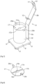
Fig.1 ] est une vue de côté du dispositif pour l'ouverture d'une bouteille de vin suivant l'invention, - [
Fig.2 ] est une vue en coupe verticale de la partie inférieure du dispositif suivant l'invention, - [
Fig.3 ] est une vue de dessus de la molette des moyens de chauffage du dispositif suivant l'invention, - [
Fig.4 ] est une vue en perspective de la molette des moyens de chauffage du dispositif suivant l'invention, - [
Fig.5 ] est une vue de face de la molette des moyens de chauffage du dispositif suivant l'invention, - [
Fig.6 ] est une vue en perspective d'une variante d'exécution du dispositif pour l'ouverture d'une bouteille de vin suivant l'invention, - [
Fig.7 ] est une vue en perspective éclatée du capot supérieur des moyens de chauffage de la variante d'exécution du dispositif suivant l'invention représenté sur lafigure 6 , - [
Fig.8 ] est une vue de dessus d'un dispositif de refroidissement du goulot du dispositif pour l'ouverture d'une bouteille suivant l'invention, - [
Fig.9 ] est une vue de côté du dispositif de refroidissement suivant l'invention représenté sur lafigure 8 .
- [
Fig.1 ] is a side view of the device for opening a bottle of wine according to the invention, - [
Fig.2 ] is a vertical sectional view of the lower part of the device according to the invention, - [
Fig.3 ] is a top view of the wheel of the heating means of the device according to the invention, - [
Fig.4 ] is a perspective view of the wheel of the heating means of the device according to the invention, - [
Fig.5 ] is a front view of the wheel of the heating means of the device according to the invention, - [
Fig.6 ] is a perspective view of an alternative embodiment of the device for opening a bottle of wine according to the invention, - [
Fig.7 ] is an exploded perspective view of the upper cover of the heating means of the alternative embodiment of the device according to the invention shown on theFigure 6 , - [
Fig.8 ] is a top view of a device for cooling the neck of the device for opening a bottle according to the invention, - [
Fig.9 ] is a side view of the cooling device according to the invention shown on thefigure 8 .
Dans la suite de la description du dispositif pour l'ouverture d'une bouteille de vin ou similaire suivant l'invention, les mêmes références numériques désignent les mêmes éléments. Par ailleurs, les différentes vues ne sont pas nécessairement tracées à l'échelle.In the remainder of the description of the device for opening a bottle of wine or the like according to the invention, the same numerical references designate the same elements. Furthermore, the different views are not necessarily drawn to scale.
On observera que le dispositif suivant l'invention est particulièrement adapté à l'ouverture de vielles bouteilles de porto dont le bouchon est dégradé ; toutefois, il est bien évident que le dispositif suivant l'invention pourra également être utilisé non seulement pour l'ouverture de bouteilles de tout type de vins doux naturels qui rencontre le même genre de dégradation de leurs bouchons en liège mais également pour l'ouverture de tout type de bouteille de vin que le bouchon soit dégradé ou non sans pour autant sortir du cadre de l'invention.It will be observed that the device according to the invention is particularly suitable for opening old port bottles whose cork is damaged; however, it is obvious that the device according to the invention could also be used not only for opening bottles of all types of natural sweet wines which encounters the same type of degradation of their cork stoppers but also for the opening of any type of wine bottle whether the cork is degraded or not without departing from the scope of the invention.
En référence aux
Il est bien évident que la pince 1 pourra présenter une forme différente telle qu'une forme de ciseaux, i.e. avec des anneaux en lieu et place des poignées 4 et/ou avec des mors 5 hémi-cylindriques en lieu et place des mors 4 hémi-annulaires par exemple sans sortir du cadre de l'invention.It is quite obvious that the pliers 1 could have a different shape such as a scissor shape, i.e. with rings in place of the handles 4 and/or with semi-cylindrical jaws 5 in place of the semi-cylindrical jaws 4 -annular for example without departing from the scope of the invention.
Par ailleurs, ladite potence 8 comporte une partie inférieure verticale 8a, i.e. s'étendant sensiblement perpendiculairement audit socle 6, et une partie supérieure inclinée 8b. Ladite potence 8 est, par exemple, obtenue dans une barre métallique dont l'extrémité inférieure est soudée dans la partie centrale de l'un des bords du socle 6 et dont la partie médiane est pliée pour former les parties inférieure 8a et supérieure 8b. Ladite partie supérieure 8b de la potence 8 forme un angle compris entre 100° et 130° avec la partie inférieure 8a de ladite potence 8, et, de préférence, un angle de 115° avec la partie inférieure 8a de ladite potence 8. De plus, l'extrémité distale de la potence 8, i.e. l'extrémité supérieure de la partie supérieure 8b de ladite potence 8, est repliée vers le haut suivant une angle d'environ 90° pour former une patte 10 dite de retenue munie d'au moins une fente 11 apte à recevoir les bras 2 de la pince 1, les poignées 4 de la pince 4 prenant appui sur la face supérieure de la patte 10. Afin de maintenir la pince 1 sensiblement parallèlement à la partie supérieure 8b de la potence 8, ladite partie supérieure 8b de la potence 8 comporte au moins un berceau 12 dans lequel prend appui les bras 2 de la pince 1.Furthermore, said bracket 8 comprises a vertical lower part 8a, ie extending substantially perpendicular to said base 6, and an inclined upper part 8b. Said bracket 8 is, for example, obtained in a metal bar whose lower end is welded in the central part of one of the edges of the base 6 and whose middle part is folded to form the lower parts 8a and upper 8b. Said upper part 8b of the bracket 8 forms an angle of between 100° and 130° with the lower part 8a of said bracket 8, and, preferably, an angle of 115° with the lower part 8a of said bracket 8. In addition , the distal end of the bracket 8, ie the upper end of the upper part 8b of said bracket 8, is folded upwards at an angle of approximately 90° to form a so-called retaining tab 10 provided with at less a slot 11 capable of receiving the arms 2 of the clamp 1, the handles 4 of the clamp 4 bearing on the upper face of the tab 10. In order to hold the clamp 1 substantially parallel to the upper part 8b of the bracket 8, said upper part 8b of the bracket 8 comprises at least one
De plus, les moyens de chauffage 7 consistent en au moins une bouteille de gaz 13 muni d'un brûleur 14 et d'une molette 15 de réglage du débit de gaz, ladite bouteille de gaz 13 s'étendant dans un carter 16 dont l'extrémité inférieure est ouverte et prend appui sur le socle 6 et dont l'extrémité supérieure est muni d'un capot supérieur 17 muni d'une ouverture 18 pour le passage du brûleur 14. Dans cet exemple particulier de réalisation, le carter 16 présente une forme cylindrique ; toutefois, il va de soi qu'il pourra présenter une forme quelconque dès lors qu'il est apte à recevoir une bouteille de gaz, sans pour autant sortir du cadre de l'invention.In addition, the heating means 7 consist of at least one
De manière avantageuse, en référence à la
Par ailleurs, en référence aux
Selon une première variante d'exécution du dispositif suivant l'invention, en référence aux
Par ailleurs, ladite potence 8 comporte une partie inférieure verticale 8a et une partie supérieure inclinée 8b. Son extrémité inférieure est soudée dans la partie centrale de l'un des bords du socle 6 et la partie médiane est pliée pour former les parties inférieure 8a et supérieure 8b. Ladite partie supérieure 8b de la potence 8 forme un angle compris entre 100° et 130° avec la partie inférieure 8a de ladite potence 8, et, de préférence, un angle de 115°. De plus, l'extrémité distale de la potence 8, i.e. l'extrémité supérieure de la partie supérieure 8b de ladite potence 8, est repliée vers le haut suivant une angle d'environ 90° pour former une patte 10 dite de retenue munie d'au moins une fente 11 à baïonnette apte à recevoir les bras 2 de la pince 1, les poignées 4 de la pince 4 prenant appui sur la face supérieure de la patte 10. Afin de maintenir la pince 1 sensiblement parallèlement à la partie supérieure 8b de la potence 8, ladite partie supérieure 8b de la potence 8 comporte au moins un berceau 12 dans lequel prend appui les bras 2 de la pince 1.Furthermore, said bracket 8 comprises a vertical lower part 8a and an inclined upper part 8b. Its lower end is welded in the central part of one of the edges of the base 6 and the middle part is folded to form the lower parts 8a and upper 8b. Said upper part 8b of the bracket 8 forms an angle of between 100° and 130° with the lower part 8a of said bracket 8, and, preferably, an angle of 115°. In addition, the distal end of the bracket 8, i.e. the upper end of the upper part 8b of said bracket 8, is folded upwards at an angle of approximately 90° to form a so-called retaining tab 10 provided with at least one bayonet slot 11 capable of receiving the arms 2 of the pliers 1, the handles 4 of the pliers 4 bearing on the upper face of the tab 10. In order to maintain the pliers 1 substantially parallel to the upper part 8b of the bracket 8, said upper part 8b of the bracket 8 comprises at least one
De plus, les moyens de chauffage 7 consistent en au moins une bouteille de gaz 13 muni d'un brûleur 14 et d'une molette 15 de réglage du débit de gaz, ladite bouteille de gaz 13 s'étendant dans un carter 16 cylindrique dont l'extrémité inférieure est ouverte et prend appui sur le socle 6 et dont l'extrémité supérieure est muni d'un capot supérieur 17 muni d'une ouverture 18 pour le passage du brûleur 14.In addition, the heating means 7 consist of at least one
Bien que cela ne soit pas représenté sur les
Le dispositif se distingue de celui décrit précédemment par le fait que le capot supérieur 17 est constitué de deux demi-disques 17a, 17ab, chaque demi-disque 17a, 17b comprenant un évidement hémicirculaire 18a et 18b respectivement dans la partie centrale du bord rectiligne et une patte recourbée 19a et 19b respectivement solidaire du bord curviligne et apte à prendre appui sur le bord supérieur du carter 16.The device differs from that described previously by the fact that the
Selon une autre variante d'exécution du dispositif suivant l'invention, non représentée sur les figures, le dispositif suivant l'invention comprend des moyens de chauffage consistant en au moins une résistance électrique chauffante couplée à un thermostat ou un rhéostat, ladite résistance électrique chauffante étant au contact, ou s'étendant à proximité, des mors de la pince lorsque cette dernière est supportée par la potence. Par exemple, la résistance électrique chauffante pourra être recouverte d'un matériau en céramique et présenter une forme circulaire. Selon une autre variante, les moyens de chauffage pourront comprendre deux résistances électriques chauffantes recouvertes de céramique et articulées autour d'un axe de manière à pivoter depuis une position ouverte où les résistances électriques chauffantes s'étendent de part et d'autre des mors de la pince jusqu'à une position fermée où les résistances électriques chauffantes coiffent les mors de la pince.According to another alternative embodiment of the device according to the invention, not shown in the figures, the device according to the invention comprises heating means consisting of at least one electrical heating resistance coupled to a thermostat or a rheostat, said electrical resistance heating being in contact, or extending close to, the jaws of the pliers when the latter is supported by the bracket. For example, the electric heating resistance may be covered with a ceramic material and have a circular shape. According to another variant, the heating means may comprise two electrical heating resistors covered with ceramic and articulated around an axis so as to pivot from an open position where the electrical heating resistors extend on either side of the jaws of the pliers to a closed position where the electrical heating resistors cap the jaws of the pliers.
Enfin, afin de procurer un choc thermique permettant de casser le goulot, en référence aux
Il va de soi que les anneaux 30 de la pince pourront être substitués par des poignées et que les mors 31 hémi-annulaires pourront être substitués par des mors hémi-cylindriques sans pour autant sortir du cadre de l'invention.It goes without saying that the
Enfin, il est bien évident que les exemples que l'on vient de donner ne sont que des illustrations particulières en aucun cas limitatives quant aux domaines d'application de l'invention.Finally, it is quite obvious that the examples which have just been given are only particular illustrations in no way limiting as to the fields of application of the invention.
Claims (12)
- A device for opening a wine bottle comprising a clamp (1) consisting of two arms (2) articulated around an axis (3), each arm (2) comprising at a first end a handle (4) or a ring and at its opposite end a jaw (5) having a semi-annular or semi-cylindrical shape, the radius of curvature of each jaw (5) being substantially equal to the radius of curvature of the neck of the wine bottle, the device comprising at least one base (6) and heating means (7), characterized in that said heating means (7) are positioned on said base (6) and in that the device further comprises a bracket (8) secured to the base (6) and comprising means for retaining the clamp (1) so that the jaws (5) of the latter extend in line with the heating means (7).
- The device according to claim 1 characterized in that said bracket (8) includes a vertical lower portion (8a), i.e. extending substantially perpendicular to said base (6), and an inclined upper portion (8b).
- The device according to claim 2 characterized in that the upper portion (8b) of the bracket (8) forms an angle comprised between 100° and 130° with the lower portion (8a) of said bracket (8).
- The device according to claim 3 characterized in that the upper portion (8b) of the bracket (8) forms an angle of 115° with the lower portion (8a) of said bracket (8).
- The device according to any one of claims 1 to 4 characterized in that the distal end of the bracket (8), i.e. the upper end of the upper portion (8b) of said bracket (8), is bent upwards at an angle of approximately 90° to form a so-called retaining tab (10) provided with at least one slot (11) capable of receiving the arms (2) of the clamp (1).
- The device according to any one of claims 1 to 5 characterized in that the upper portion (8b) of the bracket (8) includes at least one cradle (12) in which the arms (2) of the clamp (1) rest.
- The device according to any one of claims 1 to 6 characterized in that the heating means (7) consist of at least one electric heating resistor coupled to a thermostat or a rheostat, said electric heating resistor contacting the jaws (5) of the clamp (1) when the latter is supported by the bracket (8).
- The device according to any one of claims 1 to 6 characterized in that the heating means (7) consist of at least one gas cylinder (13) provided with a burner (14) and a gas flow rate adjustment knob (15), said gas cylinder (13) extending into a casing (16) whose lower end is open and rests on the base (6) and whose upper end is provided with an upper cover (17) provided with an opening (18) for the passage of the burner (14).
- The device according to claim 8 characterized in that the casing (16) has a cylindrical shape.
- The device according to claim 9 characterized in that the upper cover (17) consists of two half-discs (17a, 17b), each half-disc comprising a semicircular recess (18, 18b) in the central portion of the straight edge and a curved tab (26a, 26b) secured to the curvilinear edge and capable of resting on the upper edge of the casing (16).
- The device according to any one of claims 9 or 10 characterized in that the casing (16) includes, in its lower portion, a crown (19) secured to the inner wall of said casing (16) on which a circular plate rests (20), said plate (20) being capable of receiving the gas cylinder (13).
- The device according to any one of claims 8 to 11 characterized in that it includes a remote control means (21) of the gas flow rate adjustment knob (15), said remote control means (21) consisting of a rod (22) extending through a hole (23) formed in the casing (16) and comprising at its free ends a knob (24) and a flat head (25) respectively, said flat head (25) being capable of cooperating with a slot (26) formed in the gas flow rate adjustment knob (15).
Applications Claiming Priority (2)
| Application Number | Priority Date | Filing Date | Title |
|---|---|---|---|
| FR2001217A FR3107049B1 (en) | 2020-02-07 | 2020-02-07 | Device for opening a bottle of wine or the like with hot tongs |
| PCT/FR2021/050206 WO2021156572A1 (en) | 2020-02-07 | 2021-02-04 | Device for opening a bottle of wine or the like with a hot clamp |
Publications (3)
| Publication Number | Publication Date |
|---|---|
| EP4100357A1 EP4100357A1 (en) | 2022-12-14 |
| EP4100357B1 true EP4100357B1 (en) | 2023-11-22 |
| EP4100357C0 EP4100357C0 (en) | 2023-11-22 |
Family
ID=72178603
Family Applications (1)
| Application Number | Title | Priority Date | Filing Date |
|---|---|---|---|
| EP21707350.1A Active EP4100357B1 (en) | 2020-02-07 | 2021-02-04 | Device for opening a bottle of wine or the like with a hot clamp |
Country Status (3)
| Country | Link |
|---|---|
| EP (1) | EP4100357B1 (en) |
| FR (1) | FR3107049B1 (en) |
| WO (1) | WO2021156572A1 (en) |
-
2020
- 2020-02-07 FR FR2001217A patent/FR3107049B1/en active Active
-
2021
- 2021-02-04 WO PCT/FR2021/050206 patent/WO2021156572A1/en unknown
- 2021-02-04 EP EP21707350.1A patent/EP4100357B1/en active Active
Also Published As
| Publication number | Publication date |
|---|---|
| FR3107049B1 (en) | 2022-02-25 |
| WO2021156572A1 (en) | 2021-08-12 |
| EP4100357C0 (en) | 2023-11-22 |
| EP4100357A1 (en) | 2022-12-14 |
| FR3107049A1 (en) | 2021-08-13 |
Similar Documents
| Publication | Publication Date | Title |
|---|---|---|
| EP0091634B1 (en) | Coffee machine for domestic use | |
| EP1000574A1 (en) | Method and device for extracting a closed cartridge | |
| FR2752712A1 (en) | INFUSION APPARATUS | |
| EP1566124A1 (en) | Closure lid of a container of a household appliance for preparing food of the blender type | |
| EP1773161B1 (en) | Pourer container and brewing appliance comprising same | |
| FR2639032A1 (en) | CONTAINER HAVING A PRESSURE RELEASED COVER | |
| BE1010040A5 (en) | Locking device for bottles and use. | |
| EP4100357B1 (en) | Device for opening a bottle of wine or the like with a hot clamp | |
| EP1509735B1 (en) | Apparatus for regulating the temperature of a liquid, in particular wine | |
| FR2630316A1 (en) | Device designed for opening shellfish and, more particularly, oysters | |
| EP2593395B1 (en) | Double lever corkscrew | |
| EP3533361B1 (en) | Container having a lid with pouring stopper with bistable control | |
| FR2917730A1 (en) | TAP FOR DISPENSING THE FOODS CONTAINED IN A CONTAINER AND CULINARY PREPARING ELECTRICAL APPLIANCE PROVIDED WITH SUCH A TAP | |
| EP3937738B1 (en) | Machine for preparing infused beverages provided with a lift-up filter basket | |
| FR2660737A3 (en) | MEDIUM FOR SUPPORTING A PIN IN A MICROWAVE COMBINED ELECTRIC OVEN AND HEATING RESISTANCE. | |
| EP2291506B1 (en) | Method for the removal of sediment from sparkling wines | |
| FR2871442A1 (en) | Cooking device for bottle containing sparking wine or soda, has pumping unit introducing gas within bottle and partly housed within hollow cylindrical body, and corking device partly inserted within bottle | |
| FR2932782A1 (en) | Food cream e.g. chantilly cream, distribution device for preparing embossed pancakes, has enclosure with lower wall pierced with hole, where wall has stop and support zone for triggering element trigger liberation of cream from cartridge | |
| WO1997015221A1 (en) | Cooking receptacle with a gripping handle and means for retaining a utensil | |
| FR2817135A1 (en) | Holder for drinking glass, for use e.g. at wine tasting's, hangs around neck and has upper section with central aperture which fits around body of glass and smaller, lower section with circular slot which fits around its stem | |
| FR2770606A1 (en) | LIQUID DISTRIBUTION VALVE | |
| FR3114806A1 (en) | Device for holding a tap for tapping a container | |
| WO1998012951A1 (en) | Safety oyster-knife | |
| FR2670755A1 (en) | Container for dispensing liquid or creamy materials | |
| FR2774977A1 (en) | Opener for capped bottles |
Legal Events
| Date | Code | Title | Description |
|---|---|---|---|
| STAA | Information on the status of an ep patent application or granted ep patent |
Free format text: STATUS: UNKNOWN |
|
| STAA | Information on the status of an ep patent application or granted ep patent |
Free format text: STATUS: THE INTERNATIONAL PUBLICATION HAS BEEN MADE |
|
| PUAI | Public reference made under article 153(3) epc to a published international application that has entered the european phase |
Free format text: ORIGINAL CODE: 0009012 |
|
| STAA | Information on the status of an ep patent application or granted ep patent |
Free format text: STATUS: REQUEST FOR EXAMINATION WAS MADE |
|
| 17P | Request for examination filed |
Effective date: 20220901 |
|
| AK | Designated contracting states |
Kind code of ref document: A1 Designated state(s): AL AT BE BG CH CY CZ DE DK EE ES FI FR GB GR HR HU IE IS IT LI LT LU LV MC MK MT NL NO PL PT RO RS SE SI SK SM TR |
|
| DAV | Request for validation of the european patent (deleted) | ||
| DAX | Request for extension of the european patent (deleted) | ||
| GRAP | Despatch of communication of intention to grant a patent |
Free format text: ORIGINAL CODE: EPIDOSNIGR1 |
|
| STAA | Information on the status of an ep patent application or granted ep patent |
Free format text: STATUS: GRANT OF PATENT IS INTENDED |
|
| INTG | Intention to grant announced |
Effective date: 20230614 |
|
| GRAS | Grant fee paid |
Free format text: ORIGINAL CODE: EPIDOSNIGR3 |
|
| GRAA | (expected) grant |
Free format text: ORIGINAL CODE: 0009210 |
|
| STAA | Information on the status of an ep patent application or granted ep patent |
Free format text: STATUS: THE PATENT HAS BEEN GRANTED |
|
| AK | Designated contracting states |
Kind code of ref document: B1 Designated state(s): AL AT BE BG CH CY CZ DE DK EE ES FI FR GB GR HR HU IE IS IT LI LT LU LV MC MK MT NL NO PL PT RO RS SE SI SK SM TR |
|
| REG | Reference to a national code |
Ref country code: GB Ref legal event code: FG4D Free format text: NOT ENGLISH |
|
| REG | Reference to a national code |
Ref country code: DE Ref legal event code: R081 Ref document number: 602021007072 Country of ref document: DE Owner name: HARO, GUILLAUME, FR Free format text: FORMER OWNER: HARO, GUILLAUME, PARIS, FR |
|
| REG | Reference to a national code |
Ref country code: CH Ref legal event code: PK Free format text: RECTIFICATIONS Ref country code: CH Ref legal event code: EP |
|
| REG | Reference to a national code |
Ref country code: DE Ref legal event code: R096 Ref document number: 602021007072 Country of ref document: DE |
|
| RAP4 | Party data changed (patent owner data changed or rights of a patent transferred) |
Owner name: HARO, GUILLAUME |
|
| REG | Reference to a national code |
Ref country code: IE Ref legal event code: FG4D Free format text: LANGUAGE OF EP DOCUMENT: FRENCH |
|
| RIN2 | Information on inventor provided after grant (corrected) |
Inventor name: HARO, GUILLAUME |
|
| U01 | Request for unitary effect filed |
Effective date: 20231215 |
|
| U07 | Unitary effect registered |
Designated state(s): AT BE BG DE DK EE FI FR IT LT LU LV MT NL PT SE SI Effective date: 20231221 |
|
| U20 | Renewal fee paid [unitary effect] |
Year of fee payment: 4 Effective date: 20240216 |
|
| PG25 | Lapsed in a contracting state [announced via postgrant information from national office to epo] |
Ref country code: GR Free format text: LAPSE BECAUSE OF FAILURE TO SUBMIT A TRANSLATION OF THE DESCRIPTION OR TO PAY THE FEE WITHIN THE PRESCRIBED TIME-LIMIT Effective date: 20240223 |
|
| PG25 | Lapsed in a contracting state [announced via postgrant information from national office to epo] |
Ref country code: IS Free format text: LAPSE BECAUSE OF FAILURE TO SUBMIT A TRANSLATION OF THE DESCRIPTION OR TO PAY THE FEE WITHIN THE PRESCRIBED TIME-LIMIT Effective date: 20240322 |