EP4100262B1 - Élément de sécurité optiquement variable - Google Patents
Élément de sécurité optiquement variable Download PDFInfo
- Publication number
- EP4100262B1 EP4100262B1 EP21701661.7A EP21701661A EP4100262B1 EP 4100262 B1 EP4100262 B1 EP 4100262B1 EP 21701661 A EP21701661 A EP 21701661A EP 4100262 B1 EP4100262 B1 EP 4100262B1
- Authority
- EP
- European Patent Office
- Prior art keywords
- reflection
- security element
- colour
- enhancing coating
- relief structure
- Prior art date
- Legal status (The legal status is an assumption and is not a legal conclusion. Google has not performed a legal analysis and makes no representation as to the accuracy of the status listed.)
- Active
Links
Images


Classifications
-
- B—PERFORMING OPERATIONS; TRANSPORTING
- B42—BOOKBINDING; ALBUMS; FILES; SPECIAL PRINTED MATTER
- B42D—BOOKS; BOOK COVERS; LOOSE LEAVES; PRINTED MATTER CHARACTERISED BY IDENTIFICATION OR SECURITY FEATURES; PRINTED MATTER OF SPECIAL FORMAT OR STYLE NOT OTHERWISE PROVIDED FOR; DEVICES FOR USE THEREWITH AND NOT OTHERWISE PROVIDED FOR; MOVABLE-STRIP WRITING OR READING APPARATUS
- B42D25/00—Information-bearing cards or sheet-like structures characterised by identification or security features; Manufacture thereof
- B42D25/20—Information-bearing cards or sheet-like structures characterised by identification or security features; Manufacture thereof characterised by a particular use or purpose
- B42D25/29—Securities; Bank notes
-
- B—PERFORMING OPERATIONS; TRANSPORTING
- B42—BOOKBINDING; ALBUMS; FILES; SPECIAL PRINTED MATTER
- B42D—BOOKS; BOOK COVERS; LOOSE LEAVES; PRINTED MATTER CHARACTERISED BY IDENTIFICATION OR SECURITY FEATURES; PRINTED MATTER OF SPECIAL FORMAT OR STYLE NOT OTHERWISE PROVIDED FOR; DEVICES FOR USE THEREWITH AND NOT OTHERWISE PROVIDED FOR; MOVABLE-STRIP WRITING OR READING APPARATUS
- B42D25/00—Information-bearing cards or sheet-like structures characterised by identification or security features; Manufacture thereof
- B42D25/30—Identification or security features, e.g. for preventing forgery
- B42D25/324—Reliefs
-
- B—PERFORMING OPERATIONS; TRANSPORTING
- B42—BOOKBINDING; ALBUMS; FILES; SPECIAL PRINTED MATTER
- B42D—BOOKS; BOOK COVERS; LOOSE LEAVES; PRINTED MATTER CHARACTERISED BY IDENTIFICATION OR SECURITY FEATURES; PRINTED MATTER OF SPECIAL FORMAT OR STYLE NOT OTHERWISE PROVIDED FOR; DEVICES FOR USE THEREWITH AND NOT OTHERWISE PROVIDED FOR; MOVABLE-STRIP WRITING OR READING APPARATUS
- B42D25/00—Information-bearing cards or sheet-like structures characterised by identification or security features; Manufacture thereof
- B42D25/30—Identification or security features, e.g. for preventing forgery
- B42D25/328—Diffraction gratings; Holograms
-
- B—PERFORMING OPERATIONS; TRANSPORTING
- B42—BOOKBINDING; ALBUMS; FILES; SPECIAL PRINTED MATTER
- B42D—BOOKS; BOOK COVERS; LOOSE LEAVES; PRINTED MATTER CHARACTERISED BY IDENTIFICATION OR SECURITY FEATURES; PRINTED MATTER OF SPECIAL FORMAT OR STYLE NOT OTHERWISE PROVIDED FOR; DEVICES FOR USE THEREWITH AND NOT OTHERWISE PROVIDED FOR; MOVABLE-STRIP WRITING OR READING APPARATUS
- B42D25/00—Information-bearing cards or sheet-like structures characterised by identification or security features; Manufacture thereof
- B42D25/30—Identification or security features, e.g. for preventing forgery
- B42D25/351—Translucent or partly translucent parts, e.g. windows
-
- B—PERFORMING OPERATIONS; TRANSPORTING
- B42—BOOKBINDING; ALBUMS; FILES; SPECIAL PRINTED MATTER
- B42D—BOOKS; BOOK COVERS; LOOSE LEAVES; PRINTED MATTER CHARACTERISED BY IDENTIFICATION OR SECURITY FEATURES; PRINTED MATTER OF SPECIAL FORMAT OR STYLE NOT OTHERWISE PROVIDED FOR; DEVICES FOR USE THEREWITH AND NOT OTHERWISE PROVIDED FOR; MOVABLE-STRIP WRITING OR READING APPARATUS
- B42D25/00—Information-bearing cards or sheet-like structures characterised by identification or security features; Manufacture thereof
- B42D25/30—Identification or security features, e.g. for preventing forgery
- B42D25/36—Identification or security features, e.g. for preventing forgery comprising special materials
- B42D25/373—Metallic materials
-
- B—PERFORMING OPERATIONS; TRANSPORTING
- B42—BOOKBINDING; ALBUMS; FILES; SPECIAL PRINTED MATTER
- B42D—BOOKS; BOOK COVERS; LOOSE LEAVES; PRINTED MATTER CHARACTERISED BY IDENTIFICATION OR SECURITY FEATURES; PRINTED MATTER OF SPECIAL FORMAT OR STYLE NOT OTHERWISE PROVIDED FOR; DEVICES FOR USE THEREWITH AND NOT OTHERWISE PROVIDED FOR; MOVABLE-STRIP WRITING OR READING APPARATUS
- B42D25/00—Information-bearing cards or sheet-like structures characterised by identification or security features; Manufacture thereof
- B42D25/40—Manufacture
- B42D25/405—Marking
- B42D25/425—Marking by deformation, e.g. embossing
-
- G—PHYSICS
- G02—OPTICS
- G02B—OPTICAL ELEMENTS, SYSTEMS OR APPARATUS
- G02B27/00—Optical systems or apparatus not provided for by any of the groups G02B1/00 - G02B26/00, G02B30/00
- G02B27/02—Viewing or reading apparatus
- G02B27/06—Viewing or reading apparatus with moving picture effect
-
- G—PHYSICS
- G02—OPTICS
- G02B—OPTICAL ELEMENTS, SYSTEMS OR APPARATUS
- G02B5/00—Optical elements other than lenses
- G02B5/08—Mirrors
- G02B5/0816—Multilayer mirrors, i.e. having two or more reflecting layers
- G02B5/085—Multilayer mirrors, i.e. having two or more reflecting layers at least one of the reflecting layers comprising metal
-
- G—PHYSICS
- G02—OPTICS
- G02B—OPTICAL ELEMENTS, SYSTEMS OR APPARATUS
- G02B5/00—Optical elements other than lenses
- G02B5/08—Mirrors
- G02B5/09—Multifaceted or polygonal mirrors, e.g. polygonal scanning mirrors; Fresnel mirrors
Definitions
- the invention relates to an optically variable security element for protecting valuables, comprising a reflective surface area that exhibits at least two optically variable effects that can be recognized from different viewing directions.
- the invention also relates to a method for producing such a security element and a data carrier equipped with such a security element.
- Data storage media such as valuables or identification documents, as well as other valuable items such as branded goods, are often provided with security elements for protection. These elements allow verification of the authenticity of the data storage media and also serve as protection against unauthorized reproduction.
- security elements can, for example, take the form of a security thread embedded in a banknote, a cover foil for a banknote with a hole, an applied security strip, a self-supporting transfer element, or even a feature area printed directly onto a valuable document.
- Security elements with a viewing-angle-dependent or three-dimensional appearance play a special role in authenticity assurance, as these cannot be reproduced even with the most modern copying equipment.
- the security elements are equipped with optically variable elements that convey a different image impression to the viewer at different viewing angles. Depending on the viewing angle, they can, for example, display a different color or brightness impression, a different perspective view, and/or a different graphic motif.
- optically variable effects include, for example, motion effects, pump effects, depth effects, or flip effects, which are realized using holograms, microlenses, or micromirrors.
- Optically variable security elements which have two relief structures arranged at different heights and each provided with a color coating.
- the color coating of the The higher relief structure is structured as a grid, so that when viewing the security element, the color coating of the lower relief structure appears in the spaces between the grids, which allows a seamless transition from a first to a second appearance when tilting the security element.
- the realization of the required fine grid of the color coating is technologically very demanding.
- the grid limits the reflected light component of the higher or lower relief structure according to the area covered by grid elements or grid spaces.
- WO 2020/011392 A1 shows a similar structure with two relief structures in two height levels.
- CH 691750 A5 relates to an optical information carrier with diffraction structures.
- EP 3415964 A1 describes a multi-layer optical security element with two reflective interfaces between layers with specific refractive indices.
- EP 3216620 A1 relates to an optical security element with reflective facets in pixels that are randomly or uniformly aligned in some areas.
- WO 2020/011390 A1 is the closest state of the art, but requires two different colored coatings and also recesses or a grid in the upper coating.
- the invention is based on the object of proposing generic optically variable security elements which are particularly easy to manufacture and also have an attractive, bright visual appearance.
- the invention contains an optically variable security element as defined in claim 1.
- the first reflection-enhancing coating is present in the feature area and can be considered at least semi-transparent. It is both reflective and sufficiently transmissive to allow the second relief structure and its optically variable effect to be visible.
- the first reflection-enhancing coating is designed with a wavelength-dependent reflection and transmission in the visible spectral range.
- the higher relief structure shows the first optically variable effect in the first color and due to a transmission color effect of the first reflection-enhancing coating, the deeper relief structure shows the second optically variable effect in the second color.
- the wavelength dependence of the first reflection-enhancing coating improves the visibility of the two optically variable effects.
- the reflectance of the security element is increased.
- the first reflection-enhancing coating is selected to have a high reflectance for the first color and a high transmittance for the second color. This can increase the brightness of the two optically variable effects. For example, the sum of the reflectances for the two colors (and thus the two effects) can be greater than 1.
- the higher relief structure and/or the deeper relief structure are formed by micromirror arrangements with specularly reflecting micromirrors.
- the micromirrors are formed in particular by non-diffractive micromirrors. They therefore do not generate or utilize color splitting.
- flat mirrors, concave mirrors and/or Fresnel-type mirrors can be used.
- the lateral dimensions of the micromirrors (or individual elements of a Fresnel mirror) are expediently below 50 ⁇ m, advantageously below 20 ⁇ m, preferably around 10 ⁇ m, i.e. between 7 ⁇ m and 13 ⁇ m.
- the lateral dimensions of the micromirrors can also be above 2 ⁇ m, in particular above 3 ⁇ m or even above 5 ⁇ m.
- the pitch of the micromirrors is preferably less than 10 ⁇ m, more preferably less than 5 ⁇ m.
- relief structures in particular embossed Fresnel lenses, concave mirrors, hologram structures, nanostructures, or diffractive blazed gratings, can be used instead of micromirrors.
- Achromatic diffraction gratings so-called matte structures, can be used particularly advantageously here, as they essentially reflect white light and thus do not disrupt the color effect of the coating or any color layers by generating diffraction colors.
- the relief structures can also have subwavelength structures, in particular subwavelength gratings, which, in combination with the respective reflection-enhancing coating, determine or at least co-determine its color.
- a relief structure can represent a superposition of a micromirror structure with subwavelength gratings located thereon, whereby the orientation of the micromirrors determines the direction of the reflected light. and the subwavelength gratings modify the color effect of the reflection-enhancing layer applied to the relief structure.
- the optically variable effects of the two relief structures are not congruent; rather, they are at least partially recognizable from different viewing directions.
- the first and second relief structures reflect incident parallel light at least in certain regions into different angular ranges, wherein the two different angular ranges preferably do not overlap and are preferably separated by more than 3°, particularly preferably more than 10°.
- the two relief structures are independent relief structures. They can therefore be freely selected because they are not dependent on each other (in their relief pattern).
- a relief structure that results solely from coating another relief structure is not an independent relief structure in the present sense.
- the relief structures of the surface area do not have the same relief pattern, nor do they have the same relief pattern that is only scaled in height; rather, the two relief structures are different and have different relief patterns.
- the two independent relief structures are, in particular, different.
- the two relief structures can therefore produce similar optically variable effects, for example opposing movement effects or spatial representations visible from different viewing directions. However, due to the differences in the relief patterns, they will not both always produce the same optically variable effect in the same place.
- the formation of the higher relief structure in particular the alignment of the micromirrors of the higher micromirror arrangement and/or the formation of the deeper relief structure, in particular the orientation of the micromirrors of the deeper micromirror arrangement, can advantageously vary depending on location in order to create a given motif, in particular a three-dimensional motif or a movement motif.
- the relief pattern in particular the orientation of the micromirrors, is freely selectable and essentially determined only by the given motifs, but not by the orientation of laterally or vertically adjacent micromirrors.
- the first reflection-enhancing coating combines two inherently opposing properties.
- the first reflection-enhancing coating should have a high degree of reflection so that the optically variable effect of the first relief structure is clearly visible.
- it should also have the highest possible degree of transmission so that the optically variable effect of the second relief structure can be clearly visible.
- reflectance and transmittance are not independent of each other; rather, energy conservation implies that for any material, the sum of reflectance R, transmittance T, and absorbance A is equal to 1 (or 100%). Maximum reflection and maximum transmittance cannot therefore be achieved simultaneously, and even with negligible absorption, the sum of reflectance and transmittance cannot exceed 100%.
- the first reflection-enhancing coating expediently has a transmission of at least 35%, preferably of at least 50%, particularly preferably of at least 60%, at least in a partial range of the visible spectral range. Furthermore, the first reflection-enhancing coating has a reflection of at least 30%, preferably of at least 50%, and particularly preferably of 70% or more, at least in a partial range of the visible spectral range. As explained, the partial ranges of particularly high transmission and particularly high reflection are different within the scope of the invention, so that transmission and reflection in these ranges can simultaneously assume particularly high values, in particular values of more than 50%.
- the first reflection-enhancing coating advantageously contains one or more high-refractive-index layers, preferably dielectric high-refractive-index layers, which have a refractive index of at least 1.7, preferably at least 2.0, and particularly preferably at least 2.2, at least in a partial range of the visible spectrum.
- dielectric high-refractive-index layers made of TiO 2 or ZnS can be used.
- Even a single dielectric high-refractive-index layer can be provided with a thickness such that it reflects in a wavelength-dependent manner. For example, a 70-150 nm thick ZnS (or TiO 2) layer reflects colored, while a 40 nm thick layer reflects white.
- low-refractive-index layers for example made of MgF or SiO 2
- low-refractive-index layers for example made of MgF or SiO 2
- semiconductor materials such as silicon can also be used as high-refractive index Layers can be used. Even though these have higher absorption than high-index dielectrics, comparable effects can be achieved with thin semiconductor layers.
- multilayer systems especially with multilayer systems with multiple dielectric layers.
- three-layer systems containing two high-refractive-index layers and a low-refractive-index intermediate layer, such as a layer system consisting of a 125 nm thick TiO 2 layer, a 70 nm thick SiO 2 intermediate layer, and another 125 nm thick TiO 2 layer.
- the first reflection-enhancing coating can be a (purely) dielectric reflection-enhancing coating. More preferably, the first dielectric reflection-enhancing coating acts based on the refractive index. It is wavelength-dependently semitransparent, although it can be formed from a transparent material with a corresponding refractive index. Particularly preferably, the first dielectric refractive index-based reflection-enhancing coating in the security element is directionally neutral for light in transmission. The direction of the incoming light and the direction of the light transmitted through the first reflection-enhancing coating are thus the same.
- the reflection and transmission color effect of the first reflection-enhancing coating is independent of the viewing angle.
- Thin metal layers can also be used advantageously alone or in a multi-layer system.
- a multi-layer system is used as the first reflection-enhancing coating, which (essentially) displays a first color in reflection and a second color in transmission, independent of the viewing angle.
- a first reflection-enhancing coating can be formed by a triple-layer system of 25 nm Ag / 225 nm SiO 2 / 25 nm Ag, which displays a golden color in reflection and a blue color in transmission, each with a high reflection or transmittance of more than 50%.
- layer systems with a metal / dielectric / metal sequence can often be produced more easily or cost-effectively on existing equipment than dielectric multi-layer systems.
- due to the (albeit) low (but still significant) absorption of the thin metal layers they have a reduced maximum brightness compared to purely dielectric layer systems.
- the first reflection-enhancing coating can also be formed by a liquid crystal layer, which is preferably oriented by the higher relief structure.
- Semitransparent nanostructured metal layers in which, for example, structural colors are generated by additional subwavelength structures in the higher relief structure, are also possible.
- the appropriate layer thicknesses of the first reflection-enhancing coating and the associated sublayers in all these designs range from approximately ten to several hundred nanometers.
- Thin metal layers can also be provided with thicknesses of less than 10 nm.
- the first reflection-enhancing coating can be applied over the entire surface, since the underlying, deeper relief structure remains visible through the coating due to its semi-transparency, as explained in more detail below.
- the second reflection-enhancing coating has the highest possible reflectance, which is advantageously at least 50%, preferably at least 75%, particularly preferably at least 80% or even at least 85%.
- This high reflectance is present in at least part of the visible spectrum, advantageously in the color range in which the color of the second optically variable effect is desired.
- the second reflection-enhancing coating can advantageously also be highly reflective across the entire visible spectral range, since a desired color effect can already be created by colored transmission of the first reflection-enhancing coating and/or an intermediate color layer and/or a colored embossing lacquer layer.
- the second reflection-enhancing layer is formed as a reflective metallic coating.
- the reflection can in particular be so high that the second reflection-enhancing layer is opaque in transmission, i.e. has an optical density of at least 1.0, preferably 2.0 or more.
- Layers made of silver and aluminum, for example, can be considered as highly reflective layers across the entire visible spectral range.
- colored metallizations are used, in particular a gold-colored metallization (for example made of Au or alloys such as Al-Cu and the like) or a copper-colored metallization.
- the second reflection-enhancing layer can also be made of a combination a metallization and a translucent color layer.
- Thin-film systems can also be considered as a second reflection-enhancing layer, for example, color-shifting three-layer structures consisting of an absorber, dielectric, and reflector layer, which can be used to create blue or green reflective color contributions, which are difficult to achieve with individual metal layers.
- a second reflection-enhancing layer for example, color-shifting three-layer structures consisting of an absorber, dielectric, and reflector layer, which can be used to create blue or green reflective color contributions, which are difficult to achieve with individual metal layers.
- the first and second reflection-enhancing layers are preferably coordinated with one another to achieve a high overall reflection of the security element from both relief structures and thus a bright representation of both optically variable effects. Therefore, the reflection of the second reflection-enhancing layer is particularly advantageous, at least in the spectral range in which the first reflection-enhancing layer has a high transmission, since the brightness of the optically variable effect of the deeper relief structure results from the transmission of the first reflection-enhancing layer and the reflection of the second reflection-enhancing layer.
- the coordination of the first and second reflection-enhancing layers provides that the security element, at least in a partial area, directs light of a first wavelength range of the visible spectrum with a reflectance R1 into a first viewing angle range and light of a second wavelength range of the visible spectrum with a reflectance R2 into a second viewing angle range, where R1+R2 > 1 (or 100%) applies.
- the first wavelength range is the green spectral range
- the second wavelength range is the red spectral range
- R1 0.75
- the light transmitted through the first reflection-enhancing layer does not change its direction or changes it only slightly, to ensure that the optically variable effect of the higher-lying relief structure does not shine through to the lower-lying relief structure.
- the relief-forming layers and the layers adjoining the reflection-enhancing layers have a similar or even identical refractive index, i.e., a refractive index difference of less than 0.25, preferably less than 0.1, and particularly preferably less than 0.05.
- One or more translucent color layers can be provided between the first and second relief structures to influence the color impression of the optically variable effect of the second relief structure.
- a translucent color layer can, in particular, be non-height structured, i.e., formed as a flat layer, or it can be formed by a colored relief-forming layer, for example, a colored embossed lacquer layer.
- the different height levels at which the two relief structures are arranged advantageously have a distance in the z-direction of between 5 ⁇ m and 100 ⁇ m, preferably between 10 ⁇ m and 50 ⁇ m.
- the small vertical distance between the structures involved is not noticeable when viewing the security element.
- the vertical distance is large enough to prevent interference effects in the intermediate layer(s), so that the coloring of the security element is not disturbed by any interference colors. are also prevented by the non-conforming height profiles of the relief structures, which additionally lead to a constantly changing vertical distance between the relief structures.
- the reference point for the height level of a relief structure is the base area of the relief structure, for example, at the base of a micromirror embossing.
- a translucent color layer can also be expediently provided above the first reflection-enhancing layer in order to influence the color impression of the optically variable effect of the first relief structure.
- a high-index dielectric layer can be covered with a translucent color. Since such a color layer also influences the color and brightness of the optically variable effect of the second relief structure, light colors are preferably used for such color layers, which also transmit the desired color of the second relief structure as strongly as possible, such as yellow or a very bright red, blue, or green.
- both reflection-enhancing layers are applied to the surface pattern in an unscreened manner and, in particular, even over the entire surface.
- a particular advantage of the design according to the invention lies precisely in the fact that, despite the first reflection-enhancing coating being present in an unscreened or full-surface manner, the optically variable effect of the deeper relief structure is visible.
- the second reflection-enhancing layer can also be provided only in certain areas and thus form negative markings, in particular in the form of numbers, symbols and the like, in the security element.
- the first reflection-enhancing Coating is only present in certain areas.
- the areas in which the two different reflection-enhancing coatings are provided must overlap at least partially in the feature area.
- the two reflection-enhancing coatings are not provided over the entire surface, but in completely or almost congruent partial areas.
- a negative identifier can be designed such that both reflection-enhancing coatings are congruently left out in the form of text, symbols, value numbers and the like.
- the first reflection-enhancing layer is therefore advantageously present in the feature area without screening, i.e. without screening, but optionally with individual negative identifiers.
- the first reflection-enhancing layer is even present over the entire surface in the feature area, i.e. without screening and cutouts.
- known structuring methods can be used, in which, for example, an already structured reflection-enhancing coating is used as a mask for structuring the other layer.
- a dielectric first reflection-enhancing layer it can be advantageous to suppress the reflectance or color effect in certain areas, thus, for example, imitating a recess in the layer.
- corresponding modulation structures can be provided in the higher relief structure, which locally reduce the reflectance or color effect of the applied layer.
- moth-eye structures which can be present, for example, as regular or irregular subwavelength structures, can advantageously be used for this purpose.
- the invention further includes a data carrier as defined in claim 14 with a security element of the type described.
- the data carrier can in particular be a value document, such as a banknote, in particular a paper banknote, a polymer banknote or a film composite banknote, a share, a bond, a certificate, a voucher, a check, a high-value admission ticket, but also an identification card, such as a credit card, a bank card, a cash payment card, an authorization card, an identity card or a passport personalization page.
- the deeper relief structure is generally closer to a surface of the data carrier than the higher relief structure, which is closer to the viewer's eye.
- the security element is arranged in an opaque area of the data carrier.
- the invention also includes a method for producing an optically variable security element as defined in claim 15.
- FIG. 1 shows a schematic representation of a banknote 10 with an optically variable security element 12 according to the invention in the form of an adhesively bonded transfer element.
- the invention is not limited to transfer elements and banknotes, but can be used for all types of security elements, for example, labels on goods and packaging or for securing documents, ID cards, passports, credit cards, health cards, and the like.
- transfer elements such as patches or strips, each with or without their own carrier layer
- security threads or security strips for example, are also possible.
- the security element 12 shown conveys a three-dimensional impression to the viewer despite its flat design and simultaneously displays a binary color and effect change when the banknote 10 is tilted. From a first viewing direction, the security element 12 displays a first motif 14-A that appears to bulge out of the plane of the banknote 10, specifically, for example, a curved representation of the value number "10," appearing in a first color, for example, a bright yellow. From a second viewing direction, the security element 12 displays a second motif 14-B that appears to bulge out of the plane of the banknote 10, for example, a curved representation of a coat of arms, appearing in a second color, for example, a bright blue.
- the appearance of the security element 12 suddenly jumps from the first to the second appearance, or when tilted back, from the second to the first appearance.
- the change in the motif (value number or coat of arms) and color (yellow or blue) occurs simultaneously and without an intermediate or transitional stage in which both motifs or colors would be visible simultaneously or one motif would be visible in the color of the other motif.
- the appearance therefore jumps seamlessly between two appearances 14-A, 14-B and is therefore referred to as a binary color and effect change.
- Security elements with such appearances are generally already known from the printed DE 10 2018 005 447 A1 Compared to the security elements described there, the security element described here is easier and more cost-effective to manufacture and also shows the two optical effects with higher luminosity and thus with higher attention and recognition value.
- Fig. 2 shows a section of the security element 12 schematically in cross section.
- the security element 12 contains a flat, transparent carrier film 18, the surface extent of which defines an x-y plane and a z-axis perpendicular thereto.
- the carrier foil 18 carries a multicolored reflective surface area 20, which contains two relief structure areas 24, 34, which are arranged in the z-direction at two specific, different height levels. Since the security element of the Fig. 2 is designed for viewing in reflection from the positive z-direction, the relief structure 34 closer to the viewer 40 is referred to as the higher relief structure and the relief structure 24 further away from the viewer 40 is referred to as the lower relief structure.
- the two relief structure regions each represent micromirror embossments or micromirror arrangements 24, 34, each formed from a plurality of micromirrors inclined relative to the xy plane with lateral dimensions of approximately 10 ⁇ m.
- the local angles of inclination of the micromirrors are selected precisely so that the relief structures of the micromirror arrangements 24, 34 produce a desired optical appearance after the reflection-enhancing coating.
- angles of inclination of the micromirrors in the exemplary embodiment are selected such that the micromirror arrangement 34 generates the curved representation of the value "10" in a viewing angle range of +5° to +20° (viewing position 40-A) relative to the surface normal 42, and the micromirror arrangement 24 generates the curved representation of the coat of arms in a viewing angle range of -5° to -20° (viewing position 40-B).
- the lower micromirror arrangement 24 is provided over its entire surface with a second reflection-enhancing coating 26 in the form of a highly reflective opaque metal layer, for example an opaque aluminum layer with a reflectivity of approximately 90%, following the relief profile.
- the higher micromirror arrangement 34 is provided over its entire surface with a first reflection-enhancing coating 36 following the relief profile, which is semi-transparent and has a wavelength-dependent reflection and transmission in the visible spectral range, as shown in Fig. 3 illustrated in more detail.
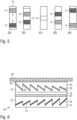
- Figure 3 shows schematically the transmittance (solid curve 60) and the reflectance (dashed curve 62) of the reflection-enhancing coating 36 as a function of the wavelength ⁇ .
- the transmittance of coating 36 is particularly high in the blue spectral range (peak 64) and even exceeds the 50% mark. Accordingly, the reflectance of coating 36 in the blue spectral range is very low (dip 66). Conversely, the reflectance of coating 36 is particularly high in the yellow and red spectral range and also significantly exceeds the 50% mark there, where again the transmittance of the coating is very low in this spectral range.
- the spectral separation of reflection and transmission makes it possible for the reflection-enhancing coating 36 to have a reflection factor of more than 50% in the yellow spectral range, on the one hand, and therefore produce a bright, golden-yellow reflection color, and to have a transmission factor of more than 50% outside the yellow spectral range, on the other hand, and therefore produce a bright, blue transmission color.
- the micromirror arrays 24, 34 are each embossed into a transparent embossed lacquer layer 22, 32 applied to the carrier film 18 and, after the application of the respective reflection-enhancing coating 26, 36, are leveled with a transparent topcoat layer 28 or 38, respectively.
- the topcoat layers preferably have substantially the same refractive index as the embossed lacquer layers 22, 32.
- the layer structure is applied, for example, with the aid of an adhesive layer 44 to the banknote paper of the banknote 10 or the substrate of another data carrier.
- the micromirrors of the higher micromirror array 34 are positioned at the glancing angle for the observer from the viewing direction 40-A, producing the curved representation of the value "10," with the first reflection-enhancing coating 36 imparting a bright, golden-yellow reflection color 52 to the image impression. Due to the semi-transparency of the reflection-enhancing coating 36, the micromirrors of the micromirror array 24 are also generally perceptible, but their orientation is far from the glancing angle and they therefore appear inconspicuous from the viewing direction 40-A. and contribute virtually nothing to the image impression. Overall, the viewer from viewing direction 40-A thus sees the golden-yellow glowing appearance 14-A of the curved value number "10" created by the micromirror arrangement 34.
- the micromirrors of the lower micromirror arrangement 24 are at the glancing angle for the observer, creating the curved representation of the coat of arms.
- the semi-transparent coating 36 transmits the blue component of the incident white light 50 as a blue transmission color 54.
- the blue transmission color 54 is reflected in the viewing direction 40-B by the opaque aluminum coating 26, which essentially acts as a mirror, without any color change as a blue reflection 56.
- the micromirrors of the higher micromirror arrangement 34 are also generally perceptible, their orientation is far from the glancing angle and they therefore appear inconspicuous from the viewing direction 40-B and contribute practically nothing to the image impression. Overall, the observer from the viewing direction 40-B sees the blue-luminous appearance 14-B of the curved coat of arms created by the micromirror arrangement 24.
- Both the yellow glowing appearance of the domed value number "10" and the blue glowing appearance 14-B of the domed coat of arms have an intensity of more than 50% of the incident light intensity, so that both color impressions appear extraordinarily bright and striking to the observer.
- the area coverage of the raster limits the relative brightness of the two relief structures, so that at most one of the brightnesses of the two appearances can be above 50%.
- the increased brightness in the present invention is made possible by spectrally separating the wavelength ranges of maximum reflection and maximum transmission. While it is physically impossible for the reflectance and the transmittance at the same wavelength to be greater than 50% at the same time, with spectral separation the reflection in one color (here, for example, yellow) and the transmission in another color (here, for example, blue) can each be greater than 50%.
- the security element as a whole can display both the first optically variable effect in the first color (yellow) and the second optically variable effect in the second color (blue) with a reflectance of more than 50%.
- a single layer of TiO 2 or ZnS with a layer thickness of approximately 10 nm to several 100 nm can be used.
- a refractive index of 1.41 for the surrounding embossed or protective varnish a reflectivity of over 40% in the green range and at the same time a very high transmission in the blue and red range, which can be 90% or more.
- Multilayers are particularly well suited for the semitransparent reflection-enhancing coating 36, as they can be specifically designed to simultaneously achieve very high reflection and very high transmission at different wavelengths.
- dielectric triple layers can be used, such as a sandwich of two 125 nm thick TiO2 layers separated by a 70 nm thick SiO2 intermediate layer.
- Such a coating exhibits almost 80% reflection at wavelengths around 500 nm while still maintaining very high transmission of more than 90%, particularly in the red spectral range.
- the color impression of the second relief structure 24, and thus of the second optically variable effect can be modified in several ways.
- a color-reflecting metal such as copper or gold
- a translucent color layer can be arranged between the two reflection-enhancing coatings 26 and 36, as in Fig. 6 illustrated.
- Such a translucent ink layer may, in particular, not be height-structured and may, for example, be applied as a flat layer to the upper or lower surface of the carrier film 18.
- one or both of the embossing lacquers 22, 32 may also be colored.
- the color impression of the second relief structure 24 is modified and then results from a combination of the transmission color of the first reflection-enhancing coating, the reflection color of the second reflection-enhancing coating and, if applicable, further color effects of color layers lying between the relief structures and/or of colored embossing varnishes.
- Figure 4 shows as a further embodiment of the invention a security element 70 in which the Fig. 2 described layers were applied to the same side of a carrier film 18.
- the security element 70 contains a first transparent embossing lacquer layer 32 with an embossed, higher-lying micromirror structure 34, a first reflection-enhancing coating 36, a second transparent embossing lacquer layer 22 applied to the coating 36 with an embossed, lower-lying micromirror structure 24, a second reflection-enhancing coating 26, a cover lacquer layer 28, and finally an adhesive layer 44 for transferring the security element 70 to a target substrate.
- the carrier film 18 is preferably designed to be releasable and is peeled off after the transfer of the security element 70. Alternatively, the carrier film 18 can also remain in the transferred layer composite if it is designed to be transparent.
- the first reflection-enhancing coating 36 is in the embodiment of the Fig. 4 formed by a dielectric three-layer structure consisting of a 125 nm thick TiO 2 layer, a 70 nm thick SiO 2 layer, and a 125 nm thick TiO 2 layer.
- the coating 36 exhibits a green reflection color with a reflectivity of almost 80% and a red transmission color with a transmittance significantly above 80%.
- a highly reflective aluminum coating is used as a second reflection-enhancing coating 26, which essentially serves as a mirror surface without its own color contribution.
- the security element 70 therefore displays the optically variable effects described below from the respective viewing directions with bright green or bright red color.
- the sum of the reflection coefficient R1 of the higher relief structure 34 in the green and the reflection coefficient R2 of the lower relief structure 24 in the red is greater than one (or 100%); specifically, each of the two reflection coefficients is greater than 0.5 (or 50%).
- the security element 70 of the Fig. 4 therefore appears particularly bright compared to conventional designs.
- both the green bar 74 of the higher micromirror arrangement 34 and the red bar 72 of the lower micromirror arrangement 24 are always visible, even in the overlapping position in which both bars 72, 74 partially or completely overlap, so that the two bars 72, 74 appear to run through each other to the observer.
- the observer sees the red and green colors of the two micromirror arrangements 24, 34 at the same location, resulting in a very bright mixed color through additive color mixing.
- the angular difference between the tilt angles at which one of the bars illuminates red or green becomes increasingly larger from the center of the security element 70 upwards or downwards, and amounts to, for example, 10° or even more at the upper or lower edge.
- the second embossing lacquer layer 22 can be applied and embossed directly onto the first reflection-enhancing coating 36.
- the embossing lacquer can be colored and then imparts an additional color contribution to the light reflected on the second reflection-enhancing coating 26.
- the second embossing lacquer layer 22 with its embossing 24 and reflection-enhancing coating 26 can also be produced on a different carrier film and then laminated onto the first carrier film 18 with the relief structure 34 and its reflection-enhancing coating 36.
- a colored laminating adhesive can be used to provide an additional color contribution.
- a transparent laminating adhesive and an additional layer of paint can be used.
- a security element 80 is shown, the structure of which largely corresponds to the structure of the security element 12 of Fig. 2
- a translucent color layer 82 is provided on the underside of the carrier film 18, which provides an additional color contribution for the light reflected by the second reflection-enhancing coating 26.
- Transparent embossing lacquer layers 22, 32 are applied, embossed with the desired relief pattern and each provided with a reflection-enhancing coating 26, 36.
- the top side of the assembly is laminated to a carrier film 86 with a release layer 88 via a laminating varnish 84.
- the underside of the assembly is provided with an adhesive layer 44 for transfer to a target substrate.
- Such an assembly is particularly suitable for producing a patch product by punching and weeding, wherein the assembly, from the release layer 88 down to the carrier film 86, is cut through with a punching tool and removed outside the patch area to be transferred.
Landscapes
- Physics & Mathematics (AREA)
- General Physics & Mathematics (AREA)
- Optics & Photonics (AREA)
- Accounting & Taxation (AREA)
- Manufacturing & Machinery (AREA)
- Business, Economics & Management (AREA)
- Engineering & Computer Science (AREA)
- Finance (AREA)
- Optical Filters (AREA)
- Credit Cards Or The Like (AREA)
- Optical Elements Other Than Lenses (AREA)
- Diffracting Gratings Or Hologram Optical Elements (AREA)
- Mechanical Light Control Or Optical Switches (AREA)
Claims (15)
- Élément de sécurité optiquement variable pour la protection d'objets de valeur, dont l'étendue de surface définit un axe z qui lui est perpendiculaire, avec une zone de surface réfléchissante qui présente au moins deux effets optiquement variables, reconnaissables à partir de différentes directions d'observation et apparaissant avec des couleurs différentes,- la zone de surface réfléchissante (20) contenant deux structures en relief indépendantes qui sont agencées à des niveaux de hauteur différents dans la direction z et forment une structure en relief située plus bas (24) et une structure en relief située plus haut (34),- la structure en relief (34) située plus haut étant pourvue d'un premier revêtement (36) augmentant la réflexion, suivant le tracé du relief, et la structure en relief (24) située plus bas étant pourvue d'un deuxième revêtement (26) augmentant la réflexion, suivant le tracé du relief,- les deux structures en relief (24, 34) se chevauchant dans une zone de caractéristique,
et- le premier revêtement augmentant la réflexion (36) étant réalisé dans le domaine spectral visible avec une réflexion et une transmission dépendant de la longueur d'onde dans le domaine spectral visible, de telle sorte que- la structure en relief (34) située plus haut présente un premier effet optiquement variable dans une première couleur, et- la structure en relief située plus bas (24) présente un deuxième effet optiquement variable à travers le premier revêtement augmentant la réflexion (36),le deuxième effet optiquement variable présentant une deuxième couleur différente. - Élément de sécurité selon la revendication 1, caractérisé en ce quegrâce à l'effet de couleur par réflexion du premier revêtement augmentant la réflexion, la structure en relief située plus haut présente le premier effet optiquement variable dans la première couleur, etgrâce à l'effet de couleur par transmission du premier revêtement augmentant la réflexion, la structure en relief située plus bas présente le deuxième effet optiquement variable dans la deuxième couleur.
- Élément de sécurité selon la revendication 1 ou 2, caractérisé en ce que la structure en relief située plus haut et/ou la structure en relief située plus bas sont formées par des agencements de micromiroirs avec des micromiroirs à réflexion dirigée, notamment avec des miroirs à effet non diffractif, et de préférence avec des miroirs plans, des miroirs concaves et/ou des miroirs de type Fresnel.
- Élément de sécurité selon au moins l'une quelconque des revendications 1 à 3, caractérisé en ce que les deux structures en relief indépendantes sont réalisées différemment.
- Élément de sécurité selon au moins l'une quelconque des revendications 1 à 4, caractérisé en ce que le premier revêtement augmentant la réflexion présente, au moins dans une partie du domaine spectral visible, une transmission d'au moins 35 %, de préférence d'au moins 50 %, de manière particulièrement préférée d'au moins 60 %.
- Élément de sécurité selon au moins l'une quelconque des revendications 1 à 5, caractérisé en ce que le premier revêtement augmentant la réflexion présente, au moins dans une partie du domaine spectral visible, une réflexion d'au moins 30 %, de préférence d'au moins 50 %, de manière particulièrement préférée d'au moins 70 %.
- Élément de sécurité selon au moins l'une quelconque des revendications 1 à 6, caractérisé en ce que le premier revêtement augmentant la réflexion contient une ou plusieurs couches hautement réfringentes, de préférence des couches diélectriques hautement réfringentes, qui présentent au moins dans une zone partielle du spectre visible un indice de réfraction d'au moins 1,7, de préférence d'au moins 2,0 et de manière particulièrement préférée d'au moins 2,2.
- Élément de sécurité selon au moins l'une quelconque des revendications 1 à 7, caractérisé en ce que le deuxième revêtement augmentant la réflexion présente, au moins dans une partie du spectre visible, un degré de réflexion d'au moins 50 %, de préférence d'au moins 75 %, de manière particulièrement préférée d'au moins 80 %, ou même d'au moins 85 %, de préférence en ce que le deuxième revêtement augmentant la réflexion est réalisé de manière opaque avec une densité optique supérieure à 1,0, notamment supérieure à 2,0.
- Élément de sécurité selon au moins l'une quelconque des revendications 1 à 8, caractérisé en ce que l'élément de sécurité dirige au moins dans une zone partielle de la lumière d'une première plage de longueurs d'onde du spectre visible avec un degré de réflexion R1 dans une première plage d'angles d'observation et de la lumière d'une deuxième plage de longueurs d'onde du spectre visible avec un degré de réflexion R2 dans une deuxième plage d'angles d'observation, avec R1+R2 > 1.
- Élément de sécurité selon au moins l'une quelconque des revendications 1 à 9, caractérisé en ce que- la première et/ou la deuxième couche augmentant la réflexion est présente dans la zone de caractéristique sans trame, de préférence sur toute la surface ; et/ou- une ou plusieurs couches de couleur translucides sont prévues entre la première et la deuxième structure en relief afin d'influencer l'impression de couleur de l'effet optiquement variable de la deuxième structure en relief ; et/ou- au-dessus de la première couche augmentant la réflexion, une ou plusieurs couches de couleur translucides sont prévues pour influencer l'impression de couleur des effets optiquement variables des première et deuxième structures en relief.
- Élément de sécurité selon au moins l'une quelconque des revendications 1 à 10, caractérisé en ce que- l'effet de couleur par transmission du premier revêtement augmentant la réflexion détermine la deuxième couleur ; ou- l'effet de couleur par transmission du premier revêtement augmentant la réflexion, conjointement avec un effet de couleur par réflexion du deuxième revêtement augmentant la réflexion et/ou avec au moins une des couches de couleur transmettant la lumière, détermine la deuxième couleur ; ou- un effet de couleur par réflexion du deuxième revêtement augmentant la réflexion et/ou l'effet de couleur d'au moins une des couches de couleur translucides détermine la deuxième couleur.
- Élément de sécurité selon au moins l'une quelconque des revendications 1 à 11, caractérisé en ce que la première et la deuxième structure en relief réfléchissent au moins par zones la lumière incidente parallèle dans des zones angulaires différentes, les deux zones angulaires différentes ne se chevauchant de préférence pas et étant de préférence séparées l'une de l'autre de plus de 3°, de manière particulièrement préférée de plus de 10°.
- Élément de sécurité selon au moins l'une quelconque des revendications 1 à 12, caractérisé en ce que la réalisation de la structure en relief située plus haut, notamment l'orientation des micromiroirs de l'agencement de micromiroirs situé plus haut et/ou la réalisation de la structure en relief située plus bas, notamment l'orientation des micromiroirs de l'agencement de micromiroirs situé plus bas, varie en fonction de l'emplacement pour produire un motif respectivement prédéfini, notamment un motif à effet tridimensionnel ou un motif de mouvement.
- Support de données avec un élément de sécurité optiquement variable selon au moins l'une quelconque des revendications 1 à 13.
- Procédé de fabrication d'un élément de sécurité optiquement variable ayant une zone de surface réfléchissante qui présente au moins deux effets optiquement variables reconnaissables à partir de différentes directions d'observation et apparaissant avec des couleurs différentes, dans lequel- un support est fourni, dont l'étendue de surface définit un plan et un axe z qui lui est perpendiculaire,- le support est pourvu d'une zone de surface réfléchissante (20) qui contient deux structures en relief indépendantes qui sont agencées à des niveaux de hauteur différents dans la direction z et qui forment une structure en relief située plus bas (24) et une structure en relief située plus haut (34),- la structure en relief (34) située plus haut est pourvue d'un premier revêtement (36) augmentant la réflexion, suivant le tracé du relief, et la structure en relief (24) située plus bas est pourvue d'un deuxième revêtement (26) augmentant la réflexion, suivant le tracé du relief,- les deux structures en relief (24, 34) sont formées de manière à se chevaucher dans une zone de caractéristique,- le premier revêtement augmentant la réflexion (36) est réalisé dans la zone de caractéristique avec une réflexion et une transmission dépendant de la longueur d'onde dans le domaine spectral visible, de telle sorte que- le relief situé plus haut (34)- grâce à l'effet de couleur de réflexion du premier revêtement augmentant la réflexion (36)- présente un premier effet optiquement variable dans une première couleur, et- la structure en relief située plus bas (24) présente, à travers le premier revêtement augmentant la réflexion (36), un deuxième effet optiquement variable qui, grâce à l'effet de couleur par transmission du premier revêtement augmentant la réflexion (36), présente une deuxième couleur différente.
Priority Applications (1)
| Application Number | Priority Date | Filing Date | Title |
|---|---|---|---|
| EP25157311.9A EP4530702A3 (fr) | 2020-02-04 | 2021-01-18 | Élément de sécurité optiquement variable |
Applications Claiming Priority (2)
| Application Number | Priority Date | Filing Date | Title |
|---|---|---|---|
| DE102020000732.5A DE102020000732A1 (de) | 2020-02-04 | 2020-02-04 | Optisch variables Sicherheitselement |
| PCT/EP2021/025014 WO2021155999A1 (fr) | 2020-02-04 | 2021-01-18 | Élément de sécurité optiquement variable |
Related Child Applications (2)
| Application Number | Title | Priority Date | Filing Date |
|---|---|---|---|
| EP25157311.9A Division-Into EP4530702A3 (fr) | 2020-02-04 | 2021-01-18 | Élément de sécurité optiquement variable |
| EP25157311.9A Division EP4530702A3 (fr) | 2020-02-04 | 2021-01-18 | Élément de sécurité optiquement variable |
Publications (2)
| Publication Number | Publication Date |
|---|---|
| EP4100262A1 EP4100262A1 (fr) | 2022-12-14 |
| EP4100262B1 true EP4100262B1 (fr) | 2025-03-19 |
Family
ID=74236132
Family Applications (2)
| Application Number | Title | Priority Date | Filing Date |
|---|---|---|---|
| EP21701661.7A Active EP4100262B1 (fr) | 2020-02-04 | 2021-01-18 | Élément de sécurité optiquement variable |
| EP25157311.9A Pending EP4530702A3 (fr) | 2020-02-04 | 2021-01-18 | Élément de sécurité optiquement variable |
Family Applications After (1)
| Application Number | Title | Priority Date | Filing Date |
|---|---|---|---|
| EP25157311.9A Pending EP4530702A3 (fr) | 2020-02-04 | 2021-01-18 | Élément de sécurité optiquement variable |
Country Status (5)
| Country | Link |
|---|---|
| US (1) | US12344022B2 (fr) |
| EP (2) | EP4100262B1 (fr) |
| CN (1) | CN115066338B (fr) |
| DE (1) | DE102020000732A1 (fr) |
| WO (1) | WO2021155999A1 (fr) |
Families Citing this family (8)
| Publication number | Priority date | Publication date | Assignee | Title |
|---|---|---|---|---|
| DE102021001898A1 (de) | 2021-04-13 | 2022-10-13 | Giesecke+Devrient Currency Technology Gmbh | Optisch variables sicherheitselement und wertdokument mit dem optisch variablen sicherheitselement |
| DE102021005911A1 (de) | 2021-11-30 | 2023-06-01 | Giesecke+Devrient Currency Technology Gmbh | Sicherheitselement mit reflektivem Flächenbereich, Datenträger und Herstellungsverfahren |
| DE102022001749A1 (de) * | 2022-05-18 | 2023-11-23 | Giesecke+Devrient Currency Technology Gmbh | Wertdokument und Verfahren zur Herstellung eines Wertdokuments |
| DE102022002470A1 (de) * | 2022-07-06 | 2024-01-11 | Giesecke+Devrient Currency Technology Gmbh | Optisch variables Flächenmuster, Wertdokument mit optisch variablem Flächenmuster und Verfahren zur Herstellung eines optisch variablen Flächenmusters |
| DE102023103092A1 (de) * | 2023-02-08 | 2024-08-08 | Giesecke+Devrient Currency Technology Gmbh | Optisch variables Sicherheitselement mit Transmissions- und Reflexionsbereich |
| DE102023125600A1 (de) | 2023-09-21 | 2025-03-27 | Giesecke+Devrient Currency Technology Gmbh | Verfahren zum Herstellen eines Sicherheitselementes mit Reliefstruktur und Sicherheitselement mit Reliefstruktur |
| DE102023126440A1 (de) * | 2023-09-28 | 2025-04-03 | Giesecke+Devrient Currency Technology Gmbh | Optisch variables Sicherheitselement, Wertgegenstand und Herstellungsverfahren |
| DE102024109646A1 (de) | 2024-04-05 | 2025-10-09 | Giesecke+Devrient Currency Technology Gmbh | Optisch variables Darstellungselement |
Family Cites Families (12)
| Publication number | Priority date | Publication date | Assignee | Title |
|---|---|---|---|---|
| CH691750A5 (de) * | 1995-11-28 | 2001-09-28 | Ovd Kinegram Ag | Optischer Informationsträger. |
| US6060143A (en) | 1996-11-14 | 2000-05-09 | Ovd Kinegram Ag | Optical information carrier |
| US8363323B2 (en) | 2002-04-03 | 2013-01-29 | De La Rue International Limited | Optically variable security device and method |
| DE602005025879D1 (de) * | 2005-09-26 | 2011-02-24 | Suisse Electronique Microtech | Ein diffraktives Sicherheitselement |
| DE102007039996B4 (de) | 2007-02-07 | 2020-09-24 | Leonhard Kurz Stiftung & Co. Kg | Sicherheitselement für ein Sicherheitsdokument und Verfahren zu seiner Herstellung |
| DE102010047250A1 (de) | 2009-12-04 | 2011-06-09 | Giesecke & Devrient Gmbh | Sicherheitselement, Wertdokument mit einem solchen Sicherheitselement sowie Herstellungsverfahren eines Sicherheitselementes |
| GB201301790D0 (en) | 2013-02-01 | 2013-03-20 | Rue De Int Ltd | Security devices and methods of manufacture thereof |
| JP6777101B2 (ja) * | 2016-02-09 | 2020-10-28 | 凸版印刷株式会社 | 偽造防止用の光学素子、偽造防止用の光学素子積層体、情報記録媒体 |
| WO2019182050A1 (fr) * | 2018-03-20 | 2019-09-26 | 凸版印刷株式会社 | Élément optique, feuille de transfert, objet d'authentification et procédé de vérification d'objet d'authentification |
| DE102018112652A1 (de) * | 2018-05-25 | 2019-11-28 | Ovd Kinegram Ag | Verfahren zur Herstellung eines Laminatkörpers und einer Laminierfolie sowie Laminatkörper und Laminierfolie |
| DE102018005447A1 (de) | 2018-07-09 | 2020-01-09 | Giesecke+Devrient Currency Technology Gmbh | Optisch variables Sicherheitselement mit reflektivem Flächenbereich |
| DE102018005454A1 (de) | 2018-07-09 | 2020-01-09 | Giesecke+Devrient Currency Technology Gmbh | Optisch variables Sicherheitselement mit reflektivem Flächenbereich |
-
2020
- 2020-02-04 DE DE102020000732.5A patent/DE102020000732A1/de not_active Withdrawn
-
2021
- 2021-01-18 EP EP21701661.7A patent/EP4100262B1/fr active Active
- 2021-01-18 US US17/796,959 patent/US12344022B2/en active Active
- 2021-01-18 EP EP25157311.9A patent/EP4530702A3/fr active Pending
- 2021-01-18 WO PCT/EP2021/025014 patent/WO2021155999A1/fr not_active Ceased
- 2021-01-18 CN CN202180012100.4A patent/CN115066338B/zh active Active
Also Published As
| Publication number | Publication date |
|---|---|
| US12344022B2 (en) | 2025-07-01 |
| US20230057603A1 (en) | 2023-02-23 |
| CN115066338B (zh) | 2024-04-30 |
| EP4530702A2 (fr) | 2025-04-02 |
| EP4100262A1 (fr) | 2022-12-14 |
| WO2021155999A1 (fr) | 2021-08-12 |
| DE102020000732A1 (de) | 2021-08-05 |
| EP4530702A3 (fr) | 2025-06-11 |
| CN115066338A (zh) | 2022-09-16 |
Similar Documents
| Publication | Publication Date | Title |
|---|---|---|
| EP4100262B1 (fr) | Élément de sécurité optiquement variable | |
| EP3820713B1 (fr) | Élément de sécurité optiquement variable à zone de surface réfléchissante | |
| EP3820714B1 (fr) | Élément de sécurité optiquement variable à zone de surface réfléchissante | |
| EP2909040B1 (fr) | Motif bidimensionnel optiquement variable | |
| EP3820715B1 (fr) | Element de securite optiquement variable avec zone de surface reflectif | |
| EP4178808B1 (fr) | Élément de sécurité optiquement variable | |
| EP3302995A1 (fr) | Élément de sécurité optiquement variable | |
| EP4013625B1 (fr) | Élément de sécurité optiquement variable | |
| EP4190582A1 (fr) | Element de securite a zone de surface reflechissante, support de donnees et procede de fabrication | |
| EP3691911A1 (fr) | Élément de sécurité transparent optiquement variable et support de données | |
| EP4217207B1 (fr) | Procédé de fabrication d'un élément de sécurité optiquement variable | |
| EP4084963B1 (fr) | Élément de sécurité optiquement variable | |
| WO2019210994A1 (fr) | Élément de sécurité, support de données et utilisation | |
| EP4217205B1 (fr) | Élément de sécurité optiquement variable comportant une zone de surface réfléchissante | |
| EP4013624B1 (fr) | Elément de sécurité optiquement variable | |
| EP4414180B1 (fr) | Element de securite optiquement variable a zone de transmission et de reflexion | |
| EP4210962B1 (fr) | Élément de sécurité optiquement variable | |
| EP3954543B1 (fr) | Élément de sécurité optique variable | |
| WO2025067977A1 (fr) | Élément de sécurité optiquement variable, article de valeur et procédé de production | |
| DE102024109646A1 (de) | Optisch variables Darstellungselement |
Legal Events
| Date | Code | Title | Description |
|---|---|---|---|
| STAA | Information on the status of an ep patent application or granted ep patent |
Free format text: STATUS: UNKNOWN |
|
| STAA | Information on the status of an ep patent application or granted ep patent |
Free format text: STATUS: THE INTERNATIONAL PUBLICATION HAS BEEN MADE |
|
| PUAI | Public reference made under article 153(3) epc to a published international application that has entered the european phase |
Free format text: ORIGINAL CODE: 0009012 |
|
| STAA | Information on the status of an ep patent application or granted ep patent |
Free format text: STATUS: REQUEST FOR EXAMINATION WAS MADE |
|
| 17P | Request for examination filed |
Effective date: 20220905 |
|
| AK | Designated contracting states |
Kind code of ref document: A1 Designated state(s): AL AT BE BG CH CY CZ DE DK EE ES FI FR GB GR HR HU IE IS IT LI LT LU LV MC MK MT NL NO PL PT RO RS SE SI SK SM TR |
|
| RAP3 | Party data changed (applicant data changed or rights of an application transferred) |
Owner name: GIESECKE+DEVRIENT CURRENCY TECHNOLOGY GMBH |
|
| TPAC | Observations filed by third parties |
Free format text: ORIGINAL CODE: EPIDOSNTIPA |
|
| DAV | Request for validation of the european patent (deleted) | ||
| DAX | Request for extension of the european patent (deleted) | ||
| P01 | Opt-out of the competence of the unified patent court (upc) registered |
Effective date: 20230519 |
|
| GRAP | Despatch of communication of intention to grant a patent |
Free format text: ORIGINAL CODE: EPIDOSNIGR1 |
|
| STAA | Information on the status of an ep patent application or granted ep patent |
Free format text: STATUS: GRANT OF PATENT IS INTENDED |
|
| INTG | Intention to grant announced |
Effective date: 20250107 |
|
| GRAS | Grant fee paid |
Free format text: ORIGINAL CODE: EPIDOSNIGR3 |
|
| GRAA | (expected) grant |
Free format text: ORIGINAL CODE: 0009210 |
|
| STAA | Information on the status of an ep patent application or granted ep patent |
Free format text: STATUS: THE PATENT HAS BEEN GRANTED |
|
| AK | Designated contracting states |
Kind code of ref document: B1 Designated state(s): AL AT BE BG CH CY CZ DE DK EE ES FI FR GB GR HR HU IE IS IT LI LT LU LV MC MK MT NL NO PL PT RO RS SE SI SK SM TR |
|
| REG | Reference to a national code |
Ref country code: GB Ref legal event code: FG4D Free format text: NOT ENGLISH |
|
| REG | Reference to a national code |
Ref country code: CH Ref legal event code: EP |
|
| REG | Reference to a national code |
Ref country code: IE Ref legal event code: FG4D Free format text: LANGUAGE OF EP DOCUMENT: GERMAN |
|
| REG | Reference to a national code |
Ref country code: DE Ref legal event code: R096 Ref document number: 502021006970 Country of ref document: DE |
|
| PG25 | Lapsed in a contracting state [announced via postgrant information from national office to epo] |
Ref country code: RS Free format text: LAPSE BECAUSE OF FAILURE TO SUBMIT A TRANSLATION OF THE DESCRIPTION OR TO PAY THE FEE WITHIN THE PRESCRIBED TIME-LIMIT Effective date: 20250619 |
|
| PG25 | Lapsed in a contracting state [announced via postgrant information from national office to epo] |
Ref country code: FI Free format text: LAPSE BECAUSE OF FAILURE TO SUBMIT A TRANSLATION OF THE DESCRIPTION OR TO PAY THE FEE WITHIN THE PRESCRIBED TIME-LIMIT Effective date: 20250319 |
|
| REG | Reference to a national code |
Ref country code: LT Ref legal event code: MG9D |
|
| PG25 | Lapsed in a contracting state [announced via postgrant information from national office to epo] |
Ref country code: NO Free format text: LAPSE BECAUSE OF FAILURE TO SUBMIT A TRANSLATION OF THE DESCRIPTION OR TO PAY THE FEE WITHIN THE PRESCRIBED TIME-LIMIT Effective date: 20250619 |
|
| PG25 | Lapsed in a contracting state [announced via postgrant information from national office to epo] |
Ref country code: HR Free format text: LAPSE BECAUSE OF FAILURE TO SUBMIT A TRANSLATION OF THE DESCRIPTION OR TO PAY THE FEE WITHIN THE PRESCRIBED TIME-LIMIT Effective date: 20250319 |
|
| PG25 | Lapsed in a contracting state [announced via postgrant information from national office to epo] |
Ref country code: LV Free format text: LAPSE BECAUSE OF FAILURE TO SUBMIT A TRANSLATION OF THE DESCRIPTION OR TO PAY THE FEE WITHIN THE PRESCRIBED TIME-LIMIT Effective date: 20250319 |
|
| PG25 | Lapsed in a contracting state [announced via postgrant information from national office to epo] |
Ref country code: GR Free format text: LAPSE BECAUSE OF FAILURE TO SUBMIT A TRANSLATION OF THE DESCRIPTION OR TO PAY THE FEE WITHIN THE PRESCRIBED TIME-LIMIT Effective date: 20250620 |
|
| REG | Reference to a national code |
Ref country code: NL Ref legal event code: MP Effective date: 20250319 |
|
| PG25 | Lapsed in a contracting state [announced via postgrant information from national office to epo] |
Ref country code: NL Free format text: LAPSE BECAUSE OF FAILURE TO SUBMIT A TRANSLATION OF THE DESCRIPTION OR TO PAY THE FEE WITHIN THE PRESCRIBED TIME-LIMIT Effective date: 20250319 |
|
| PG25 | Lapsed in a contracting state [announced via postgrant information from national office to epo] |
Ref country code: SE Free format text: LAPSE BECAUSE OF FAILURE TO SUBMIT A TRANSLATION OF THE DESCRIPTION OR TO PAY THE FEE WITHIN THE PRESCRIBED TIME-LIMIT Effective date: 20250319 |
|
| PG25 | Lapsed in a contracting state [announced via postgrant information from national office to epo] |
Ref country code: SM Free format text: LAPSE BECAUSE OF FAILURE TO SUBMIT A TRANSLATION OF THE DESCRIPTION OR TO PAY THE FEE WITHIN THE PRESCRIBED TIME-LIMIT Effective date: 20250319 |
|
| PG25 | Lapsed in a contracting state [announced via postgrant information from national office to epo] |
Ref country code: PT Free format text: LAPSE BECAUSE OF FAILURE TO SUBMIT A TRANSLATION OF THE DESCRIPTION OR TO PAY THE FEE WITHIN THE PRESCRIBED TIME-LIMIT Effective date: 20250721 Ref country code: ES Free format text: LAPSE BECAUSE OF FAILURE TO SUBMIT A TRANSLATION OF THE DESCRIPTION OR TO PAY THE FEE WITHIN THE PRESCRIBED TIME-LIMIT Effective date: 20250319 |
|
| PG25 | Lapsed in a contracting state [announced via postgrant information from national office to epo] |
Ref country code: PL Free format text: LAPSE BECAUSE OF FAILURE TO SUBMIT A TRANSLATION OF THE DESCRIPTION OR TO PAY THE FEE WITHIN THE PRESCRIBED TIME-LIMIT Effective date: 20250319 |
|
| PG25 | Lapsed in a contracting state [announced via postgrant information from national office to epo] |
Ref country code: EE Free format text: LAPSE BECAUSE OF FAILURE TO SUBMIT A TRANSLATION OF THE DESCRIPTION OR TO PAY THE FEE WITHIN THE PRESCRIBED TIME-LIMIT Effective date: 20250319 |
|
| PG25 | Lapsed in a contracting state [announced via postgrant information from national office to epo] |
Ref country code: RO Free format text: LAPSE BECAUSE OF FAILURE TO SUBMIT A TRANSLATION OF THE DESCRIPTION OR TO PAY THE FEE WITHIN THE PRESCRIBED TIME-LIMIT Effective date: 20250319 |
|
| PG25 | Lapsed in a contracting state [announced via postgrant information from national office to epo] |
Ref country code: SK Free format text: LAPSE BECAUSE OF FAILURE TO SUBMIT A TRANSLATION OF THE DESCRIPTION OR TO PAY THE FEE WITHIN THE PRESCRIBED TIME-LIMIT Effective date: 20250319 |
|
| PG25 | Lapsed in a contracting state [announced via postgrant information from national office to epo] |
Ref country code: IS Free format text: LAPSE BECAUSE OF FAILURE TO SUBMIT A TRANSLATION OF THE DESCRIPTION OR TO PAY THE FEE WITHIN THE PRESCRIBED TIME-LIMIT Effective date: 20250719 |
|
| REG | Reference to a national code |
Ref country code: DE Ref legal event code: R097 Ref document number: 502021006970 Country of ref document: DE |
|
| PG25 | Lapsed in a contracting state [announced via postgrant information from national office to epo] |
Ref country code: DK Free format text: LAPSE BECAUSE OF FAILURE TO SUBMIT A TRANSLATION OF THE DESCRIPTION OR TO PAY THE FEE WITHIN THE PRESCRIBED TIME-LIMIT Effective date: 20250319 |
|
| PLBE | No opposition filed within time limit |
Free format text: ORIGINAL CODE: 0009261 |
|
| STAA | Information on the status of an ep patent application or granted ep patent |
Free format text: STATUS: NO OPPOSITION FILED WITHIN TIME LIMIT |
|
| REG | Reference to a national code |
Ref country code: CH Ref legal event code: L10 Free format text: ST27 STATUS EVENT CODE: U-0-0-L10-L00 (AS PROVIDED BY THE NATIONAL OFFICE) Effective date: 20260128 |
|
| REG | Reference to a national code |
Ref country code: CH Ref legal event code: U11 Free format text: ST27 STATUS EVENT CODE: U-0-0-U10-U11 (AS PROVIDED BY THE NATIONAL OFFICE) Effective date: 20260201 |
|
| 26N | No opposition filed |
Effective date: 20251222 |