EP4100211B1 - Rundklammer mit festem trennsteg - Google Patents
Rundklammer mit festem trennsteg Download PDFInfo
- Publication number
- EP4100211B1 EP4100211B1 EP21702292.0A EP21702292A EP4100211B1 EP 4100211 B1 EP4100211 B1 EP 4100211B1 EP 21702292 A EP21702292 A EP 21702292A EP 4100211 B1 EP4100211 B1 EP 4100211B1
- Authority
- EP
- European Patent Office
- Prior art keywords
- clamp
- main body
- branches
- spacer
- longitudinal
- Prior art date
- Legal status (The legal status is an assumption and is not a legal conclusion. Google has not performed a legal analysis and makes no representation as to the accuracy of the status listed.)
- Active
Links
Images

Classifications
-
- B—PERFORMING OPERATIONS; TRANSPORTING
- B25—HAND TOOLS; PORTABLE POWER-DRIVEN TOOLS; MANIPULATORS
- B25B—TOOLS OR BENCH DEVICES NOT OTHERWISE PROVIDED FOR, FOR FASTENING, CONNECTING, DISENGAGING, OR HOLDING
- B25B31/00—Hand tools for applying fasteners
- B25B31/005—Hand tools for applying fasteners for temporarily connecting sheets before or during assembly operations
-
- F—MECHANICAL ENGINEERING; LIGHTING; HEATING; WEAPONS; BLASTING
- F16—ENGINEERING ELEMENTS AND UNITS; GENERAL MEASURES FOR PRODUCING AND MAINTAINING EFFECTIVE FUNCTIONING OF MACHINES OR INSTALLATIONS; THERMAL INSULATION IN GENERAL
- F16B—DEVICES FOR FASTENING OR SECURING CONSTRUCTIONAL ELEMENTS OR MACHINE PARTS TOGETHER, e.g. NAILS, BOLTS, CIRCLIPS, CLAMPS, CLIPS OR WEDGES; JOINTS OR JOINTING
- F16B19/00—Bolts without screw-thread; Pins, including deformable elements; Rivets
- F16B19/04—Rivets; Spigots or the like fastened by riveting
- F16B19/08—Hollow rivets; Multi-part rivets
- F16B19/10—Hollow rivets; Multi-part rivets fastened by expanding mechanically
- F16B19/1027—Multi-part rivets
- F16B19/1036—Blind rivets
- F16B19/109—Temporary rivets, e.g. with a spring-loaded pin
Definitions
- the present invention finds direct application in the assembly of structures, such as plates, in the aeronautical industry for example.
- the locking groove is made in an internal part housed in an end part of the main body, said internal part being fixed relative to said main body.
- the spacer has a longitudinal part of cylindrical section.
- a pinning clip intended mainly for the temporary assembly of at least two pierced parts, such as plates, in the aeronautical and space industry.
- This non-limiting example is given for a better understanding of the invention and does not exclude its use on other types of structures in related industries such as the automobile industry.
- the term “staple” is used to designate a pinning staple for the temporary assembly of pierced structures.
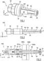
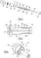
- the figures represent a clip 100 or 100' comprising a tubular main body 10, a clamp 20 held in the main body and extending axially outside said body, a spacer 30 fixed relative to the main body and making it possible to open the clamp in a radial direction, and a tie rod 40 actuating the clip by screwing onto the clamp 20 inside the main body 10, which allows said clamp to open by moving back on the fixed spacer 30.
- tubular is meant an elongated hollow shape whose straight section, which is not necessarily circular, can be polygonal or include portions of various shapes and/or diameters.
- the clip 100 makes it possible to temporarily assemble at least two pierced parts 200a and 200b, by pressing them firmly against each other, by their compression between the main body 10 and the clamp 20, said clamp passing through facing holes made in said parts.
- the resulting compression force is controlled by the tightening of the clip.
- the main body 10, according to the examples illustrated, has a generally cylindrical shape of circular section and comprises at one of its ends a terminal part 11 closed by a tip 15 intended to come into contact with the parts to be assembled.
- the end part 11 has a diameter smaller than that of the main body so as to define a shoulder against which the end piece 15 bears.
- the end part 11 may have a threaded circular external shape to receive a threaded end piece, or a non-circular external shape, for example a square or six-sided shape.
- the end part 11 comprises notches 112 to receive the corners of an internal part 13 distinct from the body 10, pierced right through, having a generally square exterior shape. The rotation of the part 13 is thus blocked in the main body 10.
- the end piece 15 can for example be fixed by thread or fitted by clipping or snap-fastening around the end part 11 of the main body 10, and defines an annular bearing face 151, preferably flat, to improve contact with the parts to be to assemble.
- the end piece 15 has a rounding at the periphery of its support surface 151 in order to limit damage to the parts in contact with said surface.
- the end piece 15 When the end part 11 is of non-circular shape, the end piece 15 has a complementary shape making it possible to attach the end piece to the end part while blocking its rotation.
- the branches 22 are regularly spaced and define a plurality of slots 221, each between two adjacent branches. According to the examples illustrated, two diametrically opposed slots 221 extend into the cylindrical part 24 of the clamp 20 to form an anti-rotation groove 241, up to near the threaded end 21.
- the spacer 30 is introduced longitudinally into two slots 221 communicating with two grooves 241 of the clamp 20, said grooves allowing the passage of the plates of the head 32 of the spacer, said head is then blocked in the groove 111 of the main body 10. So, the spacer 30 is blocked in rotation relative to the main body, and also prevents the rotation of the clamp 20, said clamp being blocked in rotation by means of the grooves 241 sliding on the flats of the head 32 of the spacer during the movement of the clamp.
- the clamp 20 is initially introduced into the holes of said parts, which are then positioned opposite each other, the clip being in the minimum tightening position with the clamp in the closed position. Still in the minimum tightening position, the clip is introduced into the parts by means of its clamp 20 until the bearing face 151 of the end piece 15 of the main body 10 comes into contact with a front face 201a of the first part 200a.
- the profile of the branches 22, and in particular the interior profile in contact with the spacer 30, has a shape adapted so that said branches begin to move away from each other from the start of tightening of the clip.
- the spacing of the branches 22 of the clamp 20 can continue until the spacer 30 passes through the hooking nose 23 as shown in the Figure 7C .
- the largest diameter D and the length L of the body can be reduced compared to the fixed spacer staples of the prior art because the hexagonal nut of the staples of the prior art has been removed, due to the postponement of the anti-rotation function of the clamps on the head of the retractor.
- the length of the body is also reduced because the clamps and the threaded rod can be manufactured in one piece, and no longer require a crimping portion or a hexagon nut. Thanks to the removal of the hexagonal nut, a greater useful length of the pliers can be engaged in the tie rod, while making it possible to reduce the total length of the assembly formed by the body and the tie rod.
- the invention makes it possible to design staples with a fixed spacer which can pass through holes which vary between 3.2 mm to 6.35 mm for a body diameter of 10.6 mm compared to a body diameter of 12.7 mm for existing staples.
Landscapes
- Engineering & Computer Science (AREA)
- General Engineering & Computer Science (AREA)
- Mechanical Engineering (AREA)
- Clamps And Clips (AREA)
- Insertion Pins And Rivets (AREA)
Claims (6)
- Klammer (100, 100') zur zeitweiligen Verbindung von mindestens zwei durchbohrten Strukturteilen (200a, 200b), mit einem rohrförmigen Hauptkörper (10), der sich entlang einer Längsachse X erstreckt und eine Auflagefläche (151) aufweist, die dazu bestimmt ist, um mit einer ersten Seite (201a) der Strukturteile in Kontakt zu kommen, einer Zange (20), die geeignet ist, gegenüberliegende Bohrungen zu durchqueren, die in den genannten Teilen ausgeführt sind, wobei die Zange entlang der Längsachse translatorisch beweglich ist und die durch die Drehung einer Zugstange (40) um die genannte Achse gedreht wird, die mit einer Gewindebohrung (41) versehen ist, die mit einem Gewindeende (21) der genannten Zange zusammenwirkt, wobei die Zange (20) flexible Arme (22) umfasst, die jeweils in einer Einhängenase (23) enden, die dazu bestimmt ist, in Kontakt mit einer letzten Seite (202b) der Strukturteile zu kommen, wobei die Arme geeignet sind, sich unter der Wirkung des Rückstoßes der Zange radial und progressiv entlang eines Abstandshalters (30) zu spreizen, der zwischen den Armen angeordnet und in Bezug auf den Hauptkörper (10) feststehend ist,wobei der Abstandshalter (30) ein Querende (32) aufweist, das drehbar in einer Verriegelungsnut (131) verriegelt ist, die in einem in Bezug auf den Hauptkörper festen Element ausgebildet ist,die Zange (20) mindestens eine Längsnut (241) aufweist, die geeignet ist, auf dem Querende zu gleiten, wenn die Zange in Bezug auf den Hauptkörper bewegt wird, und geeignet ist, die Drehung der Zange in Bezug auf das Querende zu blockieren,wobei mindestens ein Schlitz (221), der zwei benachbarte Arme (22) trennt, mit mindestens der Längsnut (241) der Zange in Verbindung steht,wobei die Klammer dadurch gekennzeichnet ist, dass die Verriegelungsnut (131) in einem Innenteil (13) ausgebildet ist, das in einem Endabschnitt (11) des Hauptkörpers untergebracht ist, wobei das Innenteil in Bezug auf den Hauptkörper feststehend ist,und dadurch, dass das Innenteil (13) eine mehrkantige Außenfläche und der Endabschnitt (11) eine mehrkantige Innenfläche aufweist.
- Klammer nach Anspruch 1, wobei die Auflagefläche (151) einer im Wesentlichen ebenen Ringfläche eines Ansatzstücks (15) entspricht, das um den Endabschnitt (11) des Hauptkörpers (10) herumpasst.
- Klammer nach Anspruch 2, wobei der Endabschnitt (11) eine nicht kreisförmige Außenfläche aufweist.
- Klammer nach einem der vorhergehenden Ansprüche, wobei der Abstandshalter (30) einen Längsabschnitt (31) mit zylindrischem Querschnitt aufweist.
- Klammer nach einem der vorhergehenden Ansprüche, wobei die Zugstange (40) innerhalb des Hauptkörpers (10) um die Längsachse X drehbar und entlang dieser Achse translatorisch bewegbar ist.
- Klammer nach einem der vorhergehenden Ansprüche, die außerdem eine Feder (50) umfasst, die in einem Raum innerhalb des Hauptkörpers (10) um die Zange (20) herum angeordnet ist, um eine Längsbewegung zwischen einer Auflagefläche (12) des Hauptkörpers (10) und einer ringförmigen Kante des Gewindeendes (21) der Zange auszuüben.
Applications Claiming Priority (2)
| Application Number | Priority Date | Filing Date | Title |
|---|---|---|---|
| FR2001167A FR3106996B1 (fr) | 2020-02-06 | 2020-02-06 | Agrafe d’épinglage à pince circulaire avec écarteur fixe |
| PCT/EP2021/052658 WO2021156362A1 (fr) | 2020-02-06 | 2021-02-04 | Agrafe d'épinglage à pince circulaire avec écarteur fixe |
Publications (2)
| Publication Number | Publication Date |
|---|---|
| EP4100211A1 EP4100211A1 (de) | 2022-12-14 |
| EP4100211B1 true EP4100211B1 (de) | 2024-07-03 |
Family
ID=70978077
Family Applications (1)
| Application Number | Title | Priority Date | Filing Date |
|---|---|---|---|
| EP21702292.0A Active EP4100211B1 (de) | 2020-02-06 | 2021-02-04 | Rundklammer mit festem trennsteg |
Country Status (5)
| Country | Link |
|---|---|
| US (1) | US12281666B2 (de) |
| EP (1) | EP4100211B1 (de) |
| JP (1) | JP7578725B2 (de) |
| FR (1) | FR3106996B1 (de) |
| WO (1) | WO2021156362A1 (de) |
Family Cites Families (17)
| Publication number | Priority date | Publication date | Assignee | Title |
|---|---|---|---|---|
| US2463731A (en) * | 1945-08-06 | 1949-03-08 | Cleveland Pneumatic Tool Co | Fastener |
| US3233504A (en) * | 1962-04-02 | 1966-02-08 | Monogram Ind Inc | Clamping device with reversed thread arrangement |
| US3260151A (en) * | 1964-04-08 | 1966-07-12 | Monogram Ind Inc | Clamping device |
| US4537542A (en) * | 1984-04-19 | 1985-08-27 | Monogram Industries, Inc. | Wedge-type low profile fastener |
| US4548533A (en) * | 1984-04-20 | 1985-10-22 | Monogram Industries, Inc. | Wedge-type fastener |
| CN85105233A (zh) * | 1985-04-17 | 1986-10-22 | 莫诺格拉姆工业有限公司 | 一种改进了的用于自动插入和抽出工具的强制松脱钢丝轴销型夹具 |
| FR2629529B1 (de) * | 1988-04-01 | 1990-12-28 | Aerospatiale | |
| WO2003069971A2 (en) * | 2002-02-15 | 2003-08-28 | Travis Mcclure | An expandable collet anchor system and method |
| US7048266B2 (en) * | 2002-10-17 | 2006-05-23 | Monogram Aerospace Fasteners, Inc. | Device and method for temporarily fastening a plurality of workpieces in response to the introduction of pressurized fluid |
| US6827345B2 (en) * | 2003-02-20 | 2004-12-07 | The Boeing Company | Wedge-lock fastener and associated installation and assembly methods |
| FR2919691B1 (fr) * | 2007-08-03 | 2009-10-30 | Lisi Aerospace Soc Par Actions | Agrafe d'epinglage a vis et son utilisation pour la fixation temporaire d'une grille de percage sur des elements a assembler |
| FR2926062B1 (fr) * | 2008-01-04 | 2010-07-30 | Airbus France | Dispositif de fixation d'un element mobilier au plancher d'un aeronef. |
| FR2927675B1 (fr) * | 2008-02-19 | 2013-02-08 | Lisi Aerospace | Dispositif de fixation provisoire et reutilisable destine au pre-assemblage d'au moins deux elements structuraux prealablement perces. |
| CA2755256C (en) * | 2009-03-13 | 2017-04-25 | Travis Mcclure | Blind fastener with integrated anti-rotation feature, systems and methods |
| FR3014969B1 (fr) * | 2013-12-16 | 2016-01-29 | Lisi Aerospace | Fixation temporaire |
| DE112017002111B4 (de) * | 2016-04-20 | 2021-07-22 | Centrix Inc. | Einseitige, temporäre Haltevorrichtung mit Konstantdruckfunktionalität |
| FR3080155B1 (fr) * | 2018-04-17 | 2020-05-15 | Lisi Aerospace | Fixation temporaire de structures |
-
2020
- 2020-02-06 FR FR2001167A patent/FR3106996B1/fr active Active
-
2021
- 2021-02-04 JP JP2022572808A patent/JP7578725B2/ja active Active
- 2021-02-04 EP EP21702292.0A patent/EP4100211B1/de active Active
- 2021-02-04 WO PCT/EP2021/052658 patent/WO2021156362A1/fr not_active Ceased
- 2021-02-04 US US17/790,723 patent/US12281666B2/en active Active
Also Published As
| Publication number | Publication date |
|---|---|
| JP2023512602A (ja) | 2023-03-27 |
| EP4100211A1 (de) | 2022-12-14 |
| WO2021156362A1 (fr) | 2021-08-12 |
| US20240263660A1 (en) | 2024-08-08 |
| US12281666B2 (en) | 2025-04-22 |
| FR3106996A1 (fr) | 2021-08-13 |
| FR3106996B1 (fr) | 2022-04-22 |
| JP7578725B2 (ja) | 2024-11-06 |
Similar Documents
| Publication | Publication Date | Title |
|---|---|---|
| EP2185826B1 (de) | Nietenklammerschraube und ihre verwendung zur vorübergehenden befestigung eines bohrgitters an zusammenzusetzenden elementen | |
| FR2845741A1 (fr) | Rivet muni de pattes elastiques | |
| EP3781825B1 (de) | Provisorisches befestigungselement für strukturen | |
| EP0336808A1 (de) | Einsteckbare Klammer mit innenliegendem Mechanismus | |
| EP3848154B1 (de) | Heftklammer mit ausgerichteter klammerzange | |
| EP3203000B1 (de) | Schloss eines öffnungsflügels mit einem elastisch einklinkbaren sockel | |
| EP2571113B1 (de) | Befestigungs- und Schnellverbindungsvorrichtung für zweiteiligen Anschluss | |
| EP4100211B1 (de) | Rundklammer mit festem trennsteg | |
| WO2016184620A1 (fr) | Element de fixation ameliore | |
| EP0325069B1 (de) | Befestigungsmutter | |
| FR2895467A1 (fr) | Agencement pour l'assemblage de deux pieces par vissage par l'intermediaire d'un ensemble vis-ecrou | |
| EP2446155B1 (de) | Plastikmutter-befestigungvorrichtung | |
| EP1231422B1 (de) | Verfahren zur Herstellung einer unverlierbaren Schraube, Fixierungstellringe für Rohrleitungen und Gebrauch von dem Prozess, die Stellringe herzustellen | |
| EP3162980A1 (de) | Verstrebungsvorrichtung für die verkleidung einer struktur | |
| FR3042830A1 (fr) | Rivet auto-perceur a haute resistance mecanique avec element de percage ejectable | |
| FR2925627A1 (fr) | Dispositif de fixation et procede de serrage d'une piece. | |
| FR3032897A1 (fr) | Dispositif de rivetage pour assemblage de precision | |
| EP2998208B1 (de) | Vorrichtung zur befestigung einer schutzummantelung einer hand auf dem griff des lenkers eines motorrads | |
| FR2676258A1 (fr) | Organe d'assemblage pour pieces. | |
| WO2013150219A1 (fr) | Dispositif d'assemblage demontable pour elements de profile | |
| FR3130331A1 (fr) | Boulon polyvalent permettant la mise en place d’un écrou à visser ou d’une bague à sertir depuis une seule extrémité en appliquant une précontrainte | |
| WO2025168745A1 (fr) | Fixation temporaire de structures | |
| FR3008444A1 (fr) | Dispositif d'accouplement entre un axe d'actionnement et une cavite interne d'une bequille de manipulation de serrure et ensemble axe et bequille de serrure comprenant un tel dispositif | |
| EP3348747A1 (de) | Schnellspannmutter und gewindestab für betonschalungen | |
| EP4123187A1 (de) | Befestigung für die vorübergehende montage von strukturen |
Legal Events
| Date | Code | Title | Description |
|---|---|---|---|
| STAA | Information on the status of an ep patent application or granted ep patent |
Free format text: STATUS: UNKNOWN |
|
| STAA | Information on the status of an ep patent application or granted ep patent |
Free format text: STATUS: THE INTERNATIONAL PUBLICATION HAS BEEN MADE |
|
| PUAI | Public reference made under article 153(3) epc to a published international application that has entered the european phase |
Free format text: ORIGINAL CODE: 0009012 |
|
| STAA | Information on the status of an ep patent application or granted ep patent |
Free format text: STATUS: REQUEST FOR EXAMINATION WAS MADE |
|
| 17P | Request for examination filed |
Effective date: 20220805 |
|
| AK | Designated contracting states |
Kind code of ref document: A1 Designated state(s): AL AT BE BG CH CY CZ DE DK EE ES FI FR GB GR HR HU IE IS IT LI LT LU LV MC MK MT NL NO PL PT RO RS SE SI SK SM TR |
|
| DAV | Request for validation of the european patent (deleted) | ||
| DAX | Request for extension of the european patent (deleted) | ||
| GRAP | Despatch of communication of intention to grant a patent |
Free format text: ORIGINAL CODE: EPIDOSNIGR1 |
|
| STAA | Information on the status of an ep patent application or granted ep patent |
Free format text: STATUS: GRANT OF PATENT IS INTENDED |
|
| INTG | Intention to grant announced |
Effective date: 20240206 |
|
| GRAS | Grant fee paid |
Free format text: ORIGINAL CODE: EPIDOSNIGR3 |
|
| GRAA | (expected) grant |
Free format text: ORIGINAL CODE: 0009210 |
|
| STAA | Information on the status of an ep patent application or granted ep patent |
Free format text: STATUS: THE PATENT HAS BEEN GRANTED |
|
| AK | Designated contracting states |
Kind code of ref document: B1 Designated state(s): AL AT BE BG CH CY CZ DE DK EE ES FI FR GB GR HR HU IE IS IT LI LT LU LV MC MK MT NL NO PL PT RO RS SE SI SK SM TR |
|
| REG | Reference to a national code |
Ref country code: CH Ref legal event code: EP |
|
| REG | Reference to a national code |
Ref country code: DE Ref legal event code: R096 Ref document number: 602021015130 Country of ref document: DE |
|
| REG | Reference to a national code |
Ref country code: LT Ref legal event code: MG9D |
|
| REG | Reference to a national code |
Ref country code: NL Ref legal event code: MP Effective date: 20240703 |
|
| PG25 | Lapsed in a contracting state [announced via postgrant information from national office to epo] |
Ref country code: PT Free format text: LAPSE BECAUSE OF FAILURE TO SUBMIT A TRANSLATION OF THE DESCRIPTION OR TO PAY THE FEE WITHIN THE PRESCRIBED TIME-LIMIT Effective date: 20241104 |
|
| REG | Reference to a national code |
Ref country code: AT Ref legal event code: MK05 Ref document number: 1699366 Country of ref document: AT Kind code of ref document: T Effective date: 20240703 |
|
| PG25 | Lapsed in a contracting state [announced via postgrant information from national office to epo] |
Ref country code: NL Free format text: LAPSE BECAUSE OF FAILURE TO SUBMIT A TRANSLATION OF THE DESCRIPTION OR TO PAY THE FEE WITHIN THE PRESCRIBED TIME-LIMIT Effective date: 20240703 |
|
| PG25 | Lapsed in a contracting state [announced via postgrant information from national office to epo] |
Ref country code: PT Free format text: LAPSE BECAUSE OF FAILURE TO SUBMIT A TRANSLATION OF THE DESCRIPTION OR TO PAY THE FEE WITHIN THE PRESCRIBED TIME-LIMIT Effective date: 20241104 Ref country code: NL Free format text: LAPSE BECAUSE OF FAILURE TO SUBMIT A TRANSLATION OF THE DESCRIPTION OR TO PAY THE FEE WITHIN THE PRESCRIBED TIME-LIMIT Effective date: 20240703 |
|
| PG25 | Lapsed in a contracting state [announced via postgrant information from national office to epo] |
Ref country code: NO Free format text: LAPSE BECAUSE OF FAILURE TO SUBMIT A TRANSLATION OF THE DESCRIPTION OR TO PAY THE FEE WITHIN THE PRESCRIBED TIME-LIMIT Effective date: 20241003 |
|
| PG25 | Lapsed in a contracting state [announced via postgrant information from national office to epo] |
Ref country code: GR Free format text: LAPSE BECAUSE OF FAILURE TO SUBMIT A TRANSLATION OF THE DESCRIPTION OR TO PAY THE FEE WITHIN THE PRESCRIBED TIME-LIMIT Effective date: 20241004 Ref country code: FI Free format text: LAPSE BECAUSE OF FAILURE TO SUBMIT A TRANSLATION OF THE DESCRIPTION OR TO PAY THE FEE WITHIN THE PRESCRIBED TIME-LIMIT Effective date: 20240703 Ref country code: PL Free format text: LAPSE BECAUSE OF FAILURE TO SUBMIT A TRANSLATION OF THE DESCRIPTION OR TO PAY THE FEE WITHIN THE PRESCRIBED TIME-LIMIT Effective date: 20240703 |
|
| PG25 | Lapsed in a contracting state [announced via postgrant information from national office to epo] |
Ref country code: BG Free format text: LAPSE BECAUSE OF FAILURE TO SUBMIT A TRANSLATION OF THE DESCRIPTION OR TO PAY THE FEE WITHIN THE PRESCRIBED TIME-LIMIT Effective date: 20240703 |
|
| PG25 | Lapsed in a contracting state [announced via postgrant information from national office to epo] |
Ref country code: LV Free format text: LAPSE BECAUSE OF FAILURE TO SUBMIT A TRANSLATION OF THE DESCRIPTION OR TO PAY THE FEE WITHIN THE PRESCRIBED TIME-LIMIT Effective date: 20240703 |
|
| PG25 | Lapsed in a contracting state [announced via postgrant information from national office to epo] |
Ref country code: IS Free format text: LAPSE BECAUSE OF FAILURE TO SUBMIT A TRANSLATION OF THE DESCRIPTION OR TO PAY THE FEE WITHIN THE PRESCRIBED TIME-LIMIT Effective date: 20241103 Ref country code: AT Free format text: LAPSE BECAUSE OF FAILURE TO SUBMIT A TRANSLATION OF THE DESCRIPTION OR TO PAY THE FEE WITHIN THE PRESCRIBED TIME-LIMIT Effective date: 20240703 |
|
| PG25 | Lapsed in a contracting state [announced via postgrant information from national office to epo] |
Ref country code: CZ Free format text: LAPSE BECAUSE OF FAILURE TO SUBMIT A TRANSLATION OF THE DESCRIPTION OR TO PAY THE FEE WITHIN THE PRESCRIBED TIME-LIMIT Effective date: 20240703 Ref country code: HR Free format text: LAPSE BECAUSE OF FAILURE TO SUBMIT A TRANSLATION OF THE DESCRIPTION OR TO PAY THE FEE WITHIN THE PRESCRIBED TIME-LIMIT Effective date: 20240703 |
|
| PG25 | Lapsed in a contracting state [announced via postgrant information from national office to epo] |
Ref country code: ES Free format text: LAPSE BECAUSE OF FAILURE TO SUBMIT A TRANSLATION OF THE DESCRIPTION OR TO PAY THE FEE WITHIN THE PRESCRIBED TIME-LIMIT Effective date: 20240703 Ref country code: RS Free format text: LAPSE BECAUSE OF FAILURE TO SUBMIT A TRANSLATION OF THE DESCRIPTION OR TO PAY THE FEE WITHIN THE PRESCRIBED TIME-LIMIT Effective date: 20241003 |
|
| PG25 | Lapsed in a contracting state [announced via postgrant information from national office to epo] |
Ref country code: RS Free format text: LAPSE BECAUSE OF FAILURE TO SUBMIT A TRANSLATION OF THE DESCRIPTION OR TO PAY THE FEE WITHIN THE PRESCRIBED TIME-LIMIT Effective date: 20241003 Ref country code: PL Free format text: LAPSE BECAUSE OF FAILURE TO SUBMIT A TRANSLATION OF THE DESCRIPTION OR TO PAY THE FEE WITHIN THE PRESCRIBED TIME-LIMIT Effective date: 20240703 Ref country code: NO Free format text: LAPSE BECAUSE OF FAILURE TO SUBMIT A TRANSLATION OF THE DESCRIPTION OR TO PAY THE FEE WITHIN THE PRESCRIBED TIME-LIMIT Effective date: 20241003 Ref country code: LV Free format text: LAPSE BECAUSE OF FAILURE TO SUBMIT A TRANSLATION OF THE DESCRIPTION OR TO PAY THE FEE WITHIN THE PRESCRIBED TIME-LIMIT Effective date: 20240703 Ref country code: IS Free format text: LAPSE BECAUSE OF FAILURE TO SUBMIT A TRANSLATION OF THE DESCRIPTION OR TO PAY THE FEE WITHIN THE PRESCRIBED TIME-LIMIT Effective date: 20241103 Ref country code: HR Free format text: LAPSE BECAUSE OF FAILURE TO SUBMIT A TRANSLATION OF THE DESCRIPTION OR TO PAY THE FEE WITHIN THE PRESCRIBED TIME-LIMIT Effective date: 20240703 Ref country code: GR Free format text: LAPSE BECAUSE OF FAILURE TO SUBMIT A TRANSLATION OF THE DESCRIPTION OR TO PAY THE FEE WITHIN THE PRESCRIBED TIME-LIMIT Effective date: 20241004 Ref country code: FI Free format text: LAPSE BECAUSE OF FAILURE TO SUBMIT A TRANSLATION OF THE DESCRIPTION OR TO PAY THE FEE WITHIN THE PRESCRIBED TIME-LIMIT Effective date: 20240703 Ref country code: ES Free format text: LAPSE BECAUSE OF FAILURE TO SUBMIT A TRANSLATION OF THE DESCRIPTION OR TO PAY THE FEE WITHIN THE PRESCRIBED TIME-LIMIT Effective date: 20240703 Ref country code: CZ Free format text: LAPSE BECAUSE OF FAILURE TO SUBMIT A TRANSLATION OF THE DESCRIPTION OR TO PAY THE FEE WITHIN THE PRESCRIBED TIME-LIMIT Effective date: 20240703 Ref country code: BG Free format text: LAPSE BECAUSE OF FAILURE TO SUBMIT A TRANSLATION OF THE DESCRIPTION OR TO PAY THE FEE WITHIN THE PRESCRIBED TIME-LIMIT Effective date: 20240703 Ref country code: AT Free format text: LAPSE BECAUSE OF FAILURE TO SUBMIT A TRANSLATION OF THE DESCRIPTION OR TO PAY THE FEE WITHIN THE PRESCRIBED TIME-LIMIT Effective date: 20240703 |
|
| REG | Reference to a national code |
Ref country code: DE Ref legal event code: R097 Ref document number: 602021015130 Country of ref document: DE |
|
| PG25 | Lapsed in a contracting state [announced via postgrant information from national office to epo] |
Ref country code: DK Free format text: LAPSE BECAUSE OF FAILURE TO SUBMIT A TRANSLATION OF THE DESCRIPTION OR TO PAY THE FEE WITHIN THE PRESCRIBED TIME-LIMIT Effective date: 20240703 Ref country code: RO Free format text: LAPSE BECAUSE OF FAILURE TO SUBMIT A TRANSLATION OF THE DESCRIPTION OR TO PAY THE FEE WITHIN THE PRESCRIBED TIME-LIMIT Effective date: 20240703 Ref country code: SM Free format text: LAPSE BECAUSE OF FAILURE TO SUBMIT A TRANSLATION OF THE DESCRIPTION OR TO PAY THE FEE WITHIN THE PRESCRIBED TIME-LIMIT Effective date: 20240703 |
|
| PG25 | Lapsed in a contracting state [announced via postgrant information from national office to epo] |
Ref country code: EE Free format text: LAPSE BECAUSE OF FAILURE TO SUBMIT A TRANSLATION OF THE DESCRIPTION OR TO PAY THE FEE WITHIN THE PRESCRIBED TIME-LIMIT Effective date: 20240703 |
|
| PG25 | Lapsed in a contracting state [announced via postgrant information from national office to epo] |
Ref country code: SK Free format text: LAPSE BECAUSE OF FAILURE TO SUBMIT A TRANSLATION OF THE DESCRIPTION OR TO PAY THE FEE WITHIN THE PRESCRIBED TIME-LIMIT Effective date: 20240703 Ref country code: IT Free format text: LAPSE BECAUSE OF FAILURE TO SUBMIT A TRANSLATION OF THE DESCRIPTION OR TO PAY THE FEE WITHIN THE PRESCRIBED TIME-LIMIT Effective date: 20240703 |
|
| PLBE | No opposition filed within time limit |
Free format text: ORIGINAL CODE: 0009261 |
|
| STAA | Information on the status of an ep patent application or granted ep patent |
Free format text: STATUS: NO OPPOSITION FILED WITHIN TIME LIMIT |
|
| 26N | No opposition filed |
Effective date: 20250404 |
|
| PG25 | Lapsed in a contracting state [announced via postgrant information from national office to epo] |
Ref country code: SE Free format text: LAPSE BECAUSE OF FAILURE TO SUBMIT A TRANSLATION OF THE DESCRIPTION OR TO PAY THE FEE WITHIN THE PRESCRIBED TIME-LIMIT Effective date: 20240703 |
|
| PG25 | Lapsed in a contracting state [announced via postgrant information from national office to epo] |
Ref country code: MC Free format text: LAPSE BECAUSE OF FAILURE TO SUBMIT A TRANSLATION OF THE DESCRIPTION OR TO PAY THE FEE WITHIN THE PRESCRIBED TIME-LIMIT Effective date: 20240703 |
|
| REG | Reference to a national code |
Ref country code: CH Ref legal event code: PL |
|
| PG25 | Lapsed in a contracting state [announced via postgrant information from national office to epo] |
Ref country code: LU Free format text: LAPSE BECAUSE OF NON-PAYMENT OF DUE FEES Effective date: 20250204 |
|
| PG25 | Lapsed in a contracting state [announced via postgrant information from national office to epo] |
Ref country code: CH Free format text: LAPSE BECAUSE OF NON-PAYMENT OF DUE FEES Effective date: 20250228 |
|
| REG | Reference to a national code |
Ref country code: BE Ref legal event code: MM Effective date: 20250228 |
|
| PG25 | Lapsed in a contracting state [announced via postgrant information from national office to epo] |
Ref country code: BE Free format text: LAPSE BECAUSE OF NON-PAYMENT OF DUE FEES Effective date: 20250228 |
|
| PG25 | Lapsed in a contracting state [announced via postgrant information from national office to epo] |
Ref country code: IE Free format text: LAPSE BECAUSE OF NON-PAYMENT OF DUE FEES Effective date: 20250204 |
|
| PGFP | Annual fee paid to national office [announced via postgrant information from national office to epo] |
Ref country code: GB Payment date: 20260219 Year of fee payment: 6 |
|
| PGFP | Annual fee paid to national office [announced via postgrant information from national office to epo] |
Ref country code: DE Payment date: 20260206 Year of fee payment: 6 |
|
| PGFP | Annual fee paid to national office [announced via postgrant information from national office to epo] |
Ref country code: FR Payment date: 20260227 Year of fee payment: 6 |