EP4100154B1 - Vorrichtung zur ausgabe und dosierung von pulverförmigen oder pastösen oder flüssigen materialien - Google Patents
Vorrichtung zur ausgabe und dosierung von pulverförmigen oder pastösen oder flüssigen materialien Download PDFInfo
- Publication number
- EP4100154B1 EP4100154B1 EP21711059.2A EP21711059A EP4100154B1 EP 4100154 B1 EP4100154 B1 EP 4100154B1 EP 21711059 A EP21711059 A EP 21711059A EP 4100154 B1 EP4100154 B1 EP 4100154B1
- Authority
- EP
- European Patent Office
- Prior art keywords
- pumps
- pump
- dispensing
- port
- respect
- Prior art date
- Legal status (The legal status is an assumption and is not a legal conclusion. Google has not performed a legal analysis and makes no representation as to the accuracy of the status listed.)
- Active
Links
Images

Classifications
-
- G—PHYSICS
- G01—MEASURING; TESTING
- G01F—MEASURING VOLUME, VOLUME FLOW, MASS FLOW OR LIQUID LEVEL; METERING BY VOLUME
- G01F13/00—Apparatus for measuring by volume and delivering fluids or fluent solid materials, not provided for in the preceding groups
- G01F13/001—Apparatus for measuring by volume and delivering fluids or fluent solid materials, not provided for in the preceding groups for fluent solid material
- G01F13/005—Apparatus for measuring by volume and delivering fluids or fluent solid materials, not provided for in the preceding groups for fluent solid material comprising a screw conveyor
-
- B—PERFORMING OPERATIONS; TRANSPORTING
- B01—PHYSICAL OR CHEMICAL PROCESSES OR APPARATUS IN GENERAL
- B01F—MIXING, e.g. DISSOLVING, EMULSIFYING OR DISPERSING
- B01F33/00—Other mixers; Mixing plants; Combinations of mixers
- B01F33/80—Mixing plants; Combinations of mixers
- B01F33/84—Mixing plants with mixing receptacles receiving material dispensed from several component receptacles, e.g. paint tins
- B01F33/841—Mixing plants with mixing receptacles receiving material dispensed from several component receptacles, e.g. paint tins with component receptacles fixed in a circular configuration on a horizontal table, e.g. the table being able to be indexed about a vertical axis
-
- B—PERFORMING OPERATIONS; TRANSPORTING
- B01—PHYSICAL OR CHEMICAL PROCESSES OR APPARATUS IN GENERAL
- B01F—MIXING, e.g. DISSOLVING, EMULSIFYING OR DISPERSING
- B01F35/00—Accessories for mixers; Auxiliary operations or auxiliary devices; Parts or details of general application
- B01F35/71—Feed mechanisms
- B01F35/717—Feed mechanisms characterised by the means for feeding the components to the mixer
- B01F35/71775—Feed mechanisms characterised by the means for feeding the components to the mixer using helical screws
-
- B—PERFORMING OPERATIONS; TRANSPORTING
- B01—PHYSICAL OR CHEMICAL PROCESSES OR APPARATUS IN GENERAL
- B01F—MIXING, e.g. DISSOLVING, EMULSIFYING OR DISPERSING
- B01F35/00—Accessories for mixers; Auxiliary operations or auxiliary devices; Parts or details of general application
- B01F35/80—Forming a predetermined ratio of the substances to be mixed
- B01F35/88—Forming a predetermined ratio of the substances to be mixed by feeding the materials batchwise
-
- B—PERFORMING OPERATIONS; TRANSPORTING
- B01—PHYSICAL OR CHEMICAL PROCESSES OR APPARATUS IN GENERAL
- B01F—MIXING, e.g. DISSOLVING, EMULSIFYING OR DISPERSING
- B01F2101/00—Mixing characterised by the nature of the mixed materials or by the application field
- B01F2101/30—Mixing paints or paint ingredients, e.g. pigments, dyes, colours, lacquers or enamel
Definitions
- the present invention refers to a device for dispensing powdery or pasty or liquid materials.
- the present invention relates to: apparatuses for volume measurement and delivery of flowing fluids or solid materials including a screw conveyor, or mixing plants with mixing outlets that receive material from multiple component outlets, e.g. paint cans, with vessels as components fixed in a circular configuration on a horizontal table, e.g. around a vertical axis.
- apparatuses for volume measurement and delivery of flowing fluids or solid materials including a screw conveyor, or mixing plants with mixing outlets that receive material from multiple component outlets, e.g. paint cans, with vessels as components fixed in a circular configuration on a horizontal table, e.g. around a vertical axis.
- the present invention refers to feeding mechanisms characterized by the means for feeding the components to the mixer by means of helical screws, non-return devices, valves, apparatuses which require an external operation adapted to each repeated and identical operation for measuring and separating a predetermined volume of fluid or fluid-solid material from a supply or container equipped with electrical control means.
- the metering pumps comprise two pump mechanisms, preferably separate, one mechanism with a relatively large dispensing capacity and another mechanism with a relatively small dispensing capacity, and a lid. With such pumps, the quantities to be dispensed can vary over a wide range. It is also preferred that the described apparatus comprises at least one weighing device for weighing at least one, preferably all the quantities dispensed. Optimization of speed and/or accuracy is further facilitated if said larger part is at least ten times larger than said smaller part.
- US-A-3,739,958 concerning a valve for the accurate control of the quantity of plastic pellets in an injection molding machine, comprising a plunger disposed in a sliding manner through the center of a screw with reciprocating motion and a valve plug attached to the injection side of the plunger.
- the force of the plasticized material delivered by the swivel screw opens the cap against an external force acting against the plunger.
- the external force moves the cap, thereby accurately controlling the quantity of shot.
- a spring is placed between the head and the end of the barrel, so as to exert a permanent extraction force on the piston.
- EP-B1-2 266 689 solves the problem of dosing precision but the possibility of selecting and operating only one pump mechanism of the two available through the fixed unit equipped with a single driver greatly reduces the effectiveness of the procedure dosage and dispensing.
- the technical problem is solved by using a two-driver system to be able to simultaneously operate the two mechanisms present in each pump.
- Object of the present invention is solving the aforementioned prior art problems by providing a device for dispensing powdery, pasty or liquid materials capable of operating the two mechanisms of each pump present in the device almost simultaneously, drastically reducing the duration of dispensing and dosing.
- a further object is providing a device for dispensing powdery or pasty or liquid materials that is as versatile as possible, separating and individually managing the opening and closing of the delivery holes downstream of each pump.
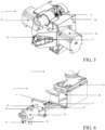
- a device for dispensing and dosing powdery, liquid, pasty or creamy materials of the invention comprises a plurality of containers 1 to contain the materials, a plurality of pumps 2, a dispensing apparatus 3, each of the pumps 2 connected to a container 1 or having a connector for releasably connecting a container 1 to the respective pump 2.
- At least some of the pumps 2 include at least two pump mechanisms, one mechanism with a relatively large delivery capacity and another mechanism with a relatively small dispensing capacity.
- At least one of the mechanisms of the pump 2 comprises a pump screw 4, 5, preferably of the auger type, housed in a first pump chamber 6 and in a second pump chamber 7, 8.
- the pumps 2 further comprise a housing 9 having the first pump chamber 6 with an inlet facing upwards positioned under the container 1, the second pump chamber 7, 8 with an outlet hole facing downwards and, during dispensing, positioned on a container, and means to open and close the outlet hole 10.
- the dispensing apparatus 3 common to all the pumps 2 comprises means 11 for positioning the dispensing apparatus 3 with respect to each of the pumps 2 and means for actuating the mechanisms 12, 13 of each of the pumps 2.
- the drive means 12, 13 comprise a first driver releasably connected to the head of the mechanism with a relatively large dispensing capacity of each of the pumps 2, and a second driver releasably connected to the head of the mechanism with a relatively small dispensing capacity of each of the pumps 2.
- the first driver and the second driver are operated independently after positioning the dispensing apparatus 3 with respect to each of the pumps 2.
- the means for opening and closing the outlet hole 10 comprise a movable hollow cylinder with a port 14, 15.
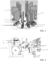
- the ports 14, 15 can be connected to the second chamber of the pump 7, 8 by means of positioning means 11 of the dispensing apparatus 3 with respect to each of the pumps 2, FIG. 2 , and through at least one elastic spring 16 compressed after positioning the dispensing apparatus 3.
- the movable hollow cylinder with an opening 14, 15 comprises a flanged portion 18 to interact with the elastic spring 16 with respect to the housing 9.
- the movable hollow cylinder with a port 14, 15 comprises at least one sliding surface 17 for a linear sliding parallel to at least one of the mechanisms of the pump 2.
- the port 14 relating to the mechanism with a relatively large delivery capacity is positioned out of phase with respect to the port 15 relating to the mechanism with a relatively small delivery capacity. In this way, it is possible to obtain different connection combinations of the port 14, 15 with the second chamber of the pump 7, 8, depending on the position reached by the movable hollow cylinder with a port 14, 15, along a linear sliding section parallel to at least one of the pump mechanisms 2.
- a rotary table 19 with respect to a vertical axis supports the plurality of containers 1 and the plurality of pumps 2, in order to be able to position each pump 2 aligned with respect to the actuation means 12, 13, FIG. 1 .
- the drive means 12, 13 are placed on a turret 20 sliding on guides for the approach of the drive means 12, 13 with respect to the rotary table 19, FIG. 2 .
- the first and second drivers of the actuation means 12, 13 are operated by means of a pair of aligned and opposed motors 21, 22.
- the first and second drivers of the actuation means 12, 13 are shaped to make a prismatic connection of the hub shaft with the respective head of the pump screw 4, 5 sliding axially.
- a cartridge 25 of each of the pumps 2 comprises the mechanism with a relatively large delivery capacity, the mechanism with a relatively small delivery capacity, the first pump chamber 6, the second pump chamber 7, 8, the hollow cylinder movable with a port 14, 15 with the flanged portion 18, the elastic spring 16 interacting with a portion of the wall 23.
- the portion of the wall 23 is adapted to releasably join a flanged edge 24 in order to constitute the housing 9.
- the cartridge 25 is easily inserted into the interface seat of the housing 9.
- the second chamber of the pump 7, 8 is also provided with a plurality of ribs (not shown) designed to ensure sealing against the product that passes into the second chamber of the pump 7, 8 itself.
- the openings of the two mechanisms in a mutually out-of-phase position that is, the opening of the mechanism with a relatively large dispensing capacity positioned out of phase with respect to the opening concerning the mechanism with a relatively small dispensing capacity, allow a management of the dosing phases.
Landscapes
- Chemical & Material Sciences (AREA)
- Chemical Kinetics & Catalysis (AREA)
- Physics & Mathematics (AREA)
- Fluid Mechanics (AREA)
- General Physics & Mathematics (AREA)
- Reciprocating Pumps (AREA)
- Control And Other Processes For Unpacking Of Materials (AREA)
- Containers And Packaging Bodies Having A Special Means To Remove Contents (AREA)
Claims (8)
- Vorrichtung zum Abgeben und Dosierung pulverisiert, flüssig, pastös, cremige Materialien, die eine Pluralität von Behältern (1) umfassen, um die Materialien zu enthalten, eine Pluralität von Pumpen (2), eine Ausgabetaste (3), jede der Pumpen (2) ) an einen Behälter (1) angeschlossen oder einen Stecker zum freizügigen Verbinden eines Behälters (1) mit der jeweiligen Pumpe (2), zumindest einige der Pumpen (2), die mindestens zwei Pumpenmechanismen umfassen, ein Mechanismus mit einer Kapazität von Relativ großer Ausgang und ein anderer Mechanismus mit einer relativ kleinen Ausgangskapazität, mindestens einer der Pumpenmechanismen (2), die eine Pumpenschraube (4), (5), vorzugsweise des Schneckentyps, in einer ersten Pumpenkammer (6) umfasst, umfasst (6) und in einer zweiten Pumpenkammer (7) (8) (8) die Pumpen (2), die ein Gehäuse (9) mit der ersten Pumpenkammer (6) mit einer Einlassöffnung in Richtung der hohen Unterkunft unter dem Behälter (1) umfassen. Die zweite Pumpenkammer (7), (8) mit einem Auslassloch nach unten und während des Dispens auf einem Behälter positioniert und zum Öffnen und Schließen der Lochauslass (10) der Ausgabetappelle (3), die allen gemeinsam sind Pumpen (2) einschließlich der Mittelwerte für die Positionierung (11) der Abgabevorrichtung (3) in Bezug auf die einzelnen Pumpen (2) und das Fahrmittel (12), (13) der Mechanismen der einzelnen Pumpen (2), charakterisiert In diesen besagten Fahren (12) umfassen (13) einen ersten Treiber, der mit einer relativ großen Lieferkapazität jeder der Pumpen (2) und einem zweiten Treiber freilich an den Kopf des Mechanismus angeschlossen ist Mit einer relativ kleinen Abgabekapazität jeder der Pumpen (2) arbeiteten der erste Treiber und der zweite Treiber nach der Positionierung des Ausgabetappers (3) in Bezug auf die einzelnen Pumpen (2),wobei die Mittel zum Öffnen und Schließen des Auslassports (10) einen beweglichen Hohlzylinder mit einem Anschluss (14), (15), dem Anschluss (14), (15) mit der zweiten Pumpenkammer (7) (8) umfassen durch diese Positionierung von Mitteln (11) des Abgabungsapparats (3) in Bezug auf jede der Pumpen (2) und durch mindestens einer elastischen Feder (16), die nach der Positionierung des Ausgabesapparats (3) komprimiert wurde.wobei der bewegliche Hohlzylinder mit einem Anschluss (14), (15) einen Flanschabschnitt (18) umfasst, um mit der elastischen Feder (16) in Bezug auf das Gehäuse (9) zusammenzuwirken.
- Vorrichtung nach Anspruch 1, dadurch gekennzeichnet, dass der bewegliche Hohlzylinder mit einer Öffnung (14), (15) mindestens eine Gleitfläche (17) zum linearen Gleiten parallel zu mindestens einem der Pumpmechanismen (2) aufweist.
- Vorrichtung nach dem vorhergehenden Anspruch, dadurch gekennzeichnet, dass das Licht (14) des Mechanismus mit relativ großer Abgabeleistung gegenüber dem Licht (15) des Mechanismus mit relativ geringer Abgabeleistung phasenverschoben angeordnet ist, um unterschiedliche Verbindungskombinationen des Anschlusses (14), (15) mit der zweiten Pumpenkammer (7), (8) zu erhalten, abhängig von der Position, die der mobile Hohlzylinder mit einem Anschluss (14) erreicht (15), entlang einer linearen Gleitstrecke parallel zu mindestens einem der Pumpmechanismen (2).
- Vorrichtung nach Anspruch 1, dadurch gekennzeichnet, dass ein Drehtisch (19) bezüglich einer vertikalen Achse die mehreren Behälter (1) und die mehreren Pumpen (2) trägt, um jede Pumpe (2) zueinander ausgerichtet zu positionieren zu den Antriebsmitteln (12), (13), wobei die Antriebsmittel (12), (13) auf einem Revolver (20) angeordnet sind, der auf Führungen für die Annäherung der Antriebsmittel (12), (13) in Bezug auf die gleitet Tisch drehbar (19).
- Vorrichtung nach Anspruch 1, dadurch gekennzeichnet, dass die ersten und zweiten Antriebsmittels (12), (13) durch ein Paar ausgerichteter und gegenläufiger Motoren (21), (22) betrieben werden.
- Vorrichtung nach Anspruch 1, dadurch gekennzeichnet, dass der erste oder zweite Mitnehmer des Antriebsmittels (12), (13) so geformt ist, dass eine prismatische Verbindung der Nabenwelle mit dem jeweiligen Kopf der Pumpenschraube (4) entsteht. (5) axial verschiebbar.
- Vorrichtung nach einem der vorhergehenden Ansprüche, dadurch gekennzeichnet, dass sie eine Kartusche (25) für jede der Pumpen (2) umfasst, wobei die Kartusche (25) den Mechanismus mit einer relativ großen Abgabekapazität umfasst, wobei der Mechanismus eine relativ große Abgabekapazität aufweist kleine Fördermenge, die erste Pumpenkammer (6), die zweite Pumpenkammer (7), (8), der bewegliche Hohlzylinder mit einem Anschluss (14), (15) mit dem Flanschteil (18), die Federfeder (16) mit einem Wandabschnitt (23) zusammenwirkt, wobei der Wandabschnitt (23) dazu ausgelegt ist, sich lösbar mit einem Flanschrand (24) zu verbinden, um das Gehäuse (9) zu bilden.
- Vorrichtung nach einem der vorhergehenden Ansprüche, dadurch gekennzeichnet, dass die zweite Pumpenkammer (7), (8) ebenfalls mit einer Vielzahl von Rippen ausgestattet ist, die eine Abdichtung gegenüber dem in die zweite Pumpenkammer (7), (8) gelangenden Produkt gewährleisten sollen.
Applications Claiming Priority (2)
| Application Number | Priority Date | Filing Date | Title |
|---|---|---|---|
| IT102020000002281A IT202000002281A1 (it) | 2020-02-05 | 2020-02-05 | Dispositivo per erogare e dosare materiali in polvere o pastosi o liquidi |
| PCT/IT2021/050023 WO2021156897A1 (en) | 2020-02-05 | 2021-01-26 | Device for dispensing and dosing powdery or pasty or liquid materials |
Publications (2)
| Publication Number | Publication Date |
|---|---|
| EP4100154A1 EP4100154A1 (de) | 2022-12-14 |
| EP4100154B1 true EP4100154B1 (de) | 2024-07-31 |
Family
ID=70480544
Family Applications (1)
| Application Number | Title | Priority Date | Filing Date |
|---|---|---|---|
| EP21711059.2A Active EP4100154B1 (de) | 2020-02-05 | 2021-01-26 | Vorrichtung zur ausgabe und dosierung von pulverförmigen oder pastösen oder flüssigen materialien |
Country Status (5)
| Country | Link |
|---|---|
| US (1) | US12018967B2 (de) |
| EP (1) | EP4100154B1 (de) |
| CN (1) | CN115209981B (de) |
| IT (1) | IT202000002281A1 (de) |
| WO (1) | WO2021156897A1 (de) |
Families Citing this family (3)
| Publication number | Priority date | Publication date | Assignee | Title |
|---|---|---|---|---|
| US12606331B2 (en) * | 2024-08-07 | 2026-04-21 | The Paint'n Packet, LLC | Paint sample packet-making apparatus |
| US12420245B1 (en) * | 2025-04-24 | 2025-09-23 | Prince Mohammad Bin Fahd University | Method for powder flow control |
| US12440812B1 (en) * | 2025-04-24 | 2025-10-14 | Prince Mohammad Bin Fahd University | Multi powder mixing system |
Family Cites Families (14)
| Publication number | Priority date | Publication date | Assignee | Title |
|---|---|---|---|---|
| US3739958A (en) | 1971-12-10 | 1973-06-19 | Beloit Corp | Non-return valve for injection molding machine |
| EP1176402A1 (de) * | 2000-07-28 | 2002-01-30 | Societe Des Produits Nestle S.A. | Dosiervorrichtung und Spender mit einer solchen Vorrichtung |
| US6640999B2 (en) * | 2001-11-13 | 2003-11-04 | Unilever Home & Personal Care Usa, Division Of Conopco, Inc. | Dose dispensing pump for dispensing two or more materials |
| US7311223B2 (en) * | 2004-05-07 | 2007-12-25 | Fluid Management, Inc. | Apparatus for dispensing a plurality of powders and method of compounding substances |
| US7134573B2 (en) * | 2004-05-07 | 2006-11-14 | Fluid Management, Inc. | Apparatus for dispensing a plurality of powders and method of compounding substances |
| US8729410B2 (en) * | 2005-03-03 | 2014-05-20 | Cabinplant International A/S | Arrangement for conveying controlled portions of a product material to a combinational weighing system consisting of a transport screw with a quick release mechanism |
| US7726520B2 (en) * | 2005-12-22 | 2010-06-01 | Innopak Inc. | Metered dispenser with feed-containing piston drive mechanism |
| JP5964069B2 (ja) * | 2012-02-06 | 2016-08-03 | 花王株式会社 | 泡吐出器 |
| US20150183531A1 (en) * | 2012-06-04 | 2015-07-02 | Bart Peter Verhoest | Feeder Unit, a Feeder Module Comprising a plurality of Feeder Units, and Method for Discharging a Constant Mass Flow of One or More Powders Into a Receiving Container |
| DE102013215599B4 (de) * | 2013-08-07 | 2017-12-07 | Aptar Radolfzell Gmbh | Pumpeinrichtung und Spender für flüssige oder pastöse Medien |
| US10455969B2 (en) * | 2013-12-20 | 2019-10-29 | Societe Des Produits Nestle S.A. | Beverage dispenser with powder container |
| DE102015207342B4 (de) * | 2015-04-22 | 2021-09-23 | BSH Hausgeräte GmbH | Wäschepflegegerät mit einem Dosiersystem |
| IT201700045807A1 (it) * | 2017-04-28 | 2017-07-28 | Hero Europe S R L | Dispositivo, sistema di dosaggio per prodotti in polvere, liquidi, pastosi o cremosi e macchina dispensatrice comprendente tale dispositivo |
| CN108311025B (zh) * | 2018-02-23 | 2018-12-21 | 浙江春晖磁电科技有限公司 | 一种陶瓷-金属复合材料设备 |
-
2020
- 2020-02-05 IT IT102020000002281A patent/IT202000002281A1/it unknown
-
2021
- 2021-01-26 WO PCT/IT2021/050023 patent/WO2021156897A1/en not_active Ceased
- 2021-01-26 CN CN202180015969.4A patent/CN115209981B/zh active Active
- 2021-01-26 EP EP21711059.2A patent/EP4100154B1/de active Active
- 2021-01-26 US US17/760,184 patent/US12018967B2/en active Active
Also Published As
| Publication number | Publication date |
|---|---|
| WO2021156897A1 (en) | 2021-08-12 |
| CN115209981B (zh) | 2024-03-22 |
| CN115209981A (zh) | 2022-10-18 |
| IT202000002281A1 (it) | 2020-05-05 |
| US20230069971A1 (en) | 2023-03-09 |
| US12018967B2 (en) | 2024-06-25 |
| EP4100154A1 (de) | 2022-12-14 |
Similar Documents
| Publication | Publication Date | Title |
|---|---|---|
| EP4100154B1 (de) | Vorrichtung zur ausgabe und dosierung von pulverförmigen oder pastösen oder flüssigen materialien | |
| KR101780689B1 (ko) | 유체 제품을 송출하기 위한 장치 및 관련 방법 | |
| CN100339625C (zh) | 阀组件 | |
| US8240513B2 (en) | Fluid dispenser with nested displacement members | |
| US4014463A (en) | Plural component dispenser | |
| US4878601A (en) | Liquid dispenser | |
| KR101968427B1 (ko) | 계량 디스펜서, 및 계량 디스펜서를 위한 배출 헤드 | |
| KR101897584B1 (ko) | 혼합을 위한 방법 및 기구 | |
| US6161733A (en) | Shutter valve dispenser | |
| EP3589171B1 (de) | Spendervorrichtung | |
| US20050072815A1 (en) | Apparatus for dispensing precise amounts of a non-compressible fluid | |
| CN102460085B (zh) | 具有嵌套的位移构件的流体分配器 | |
| US6637625B1 (en) | Continuous positive displacement metering valve | |
| US20060060611A1 (en) | Metering pump, nozzle holder and system for the direct metering | |
| WO2006093591A1 (en) | Fluid metering system | |
| GB2348252A (en) | Apparatus for dispensing fluids |
Legal Events
| Date | Code | Title | Description |
|---|---|---|---|
| STAA | Information on the status of an ep patent application or granted ep patent |
Free format text: STATUS: UNKNOWN |
|
| STAA | Information on the status of an ep patent application or granted ep patent |
Free format text: STATUS: THE INTERNATIONAL PUBLICATION HAS BEEN MADE |
|
| PUAI | Public reference made under article 153(3) epc to a published international application that has entered the european phase |
Free format text: ORIGINAL CODE: 0009012 |
|
| STAA | Information on the status of an ep patent application or granted ep patent |
Free format text: STATUS: REQUEST FOR EXAMINATION WAS MADE |
|
| 17P | Request for examination filed |
Effective date: 20220801 |
|
| AK | Designated contracting states |
Kind code of ref document: A1 Designated state(s): AL AT BE BG CH CY CZ DE DK EE ES FI FR GB GR HR HU IE IS IT LI LT LU LV MC MK MT NL NO PL PT RO RS SE SI SK SM TR |
|
| DAV | Request for validation of the european patent (deleted) | ||
| DAX | Request for extension of the european patent (deleted) | ||
| STAA | Information on the status of an ep patent application or granted ep patent |
Free format text: STATUS: EXAMINATION IS IN PROGRESS |
|
| 17Q | First examination report despatched |
Effective date: 20230915 |
|
| REG | Reference to a national code |
Ref country code: DE Ref legal event code: R079 Free format text: PREVIOUS MAIN CLASS: B01F0013100000 Ipc: B01F0033841000 Ref country code: DE Ref legal event code: R079 Ref document number: 602021016460 Country of ref document: DE Free format text: PREVIOUS MAIN CLASS: B01F0013100000 Ipc: B01F0033841000 |
|
| GRAP | Despatch of communication of intention to grant a patent |
Free format text: ORIGINAL CODE: EPIDOSNIGR1 |
|
| RIC1 | Information provided on ipc code assigned before grant |
Ipc: G01F 13/00 20060101ALI20240209BHEP Ipc: B01F 35/88 20220101ALI20240209BHEP Ipc: B01F 35/71 20220101ALI20240209BHEP Ipc: B01F 33/841 20220101AFI20240209BHEP |
|
| STAA | Information on the status of an ep patent application or granted ep patent |
Free format text: STATUS: GRANT OF PATENT IS INTENDED |
|
| INTG | Intention to grant announced |
Effective date: 20240321 |
|
| GRAS | Grant fee paid |
Free format text: ORIGINAL CODE: EPIDOSNIGR3 |
|
| GRAA | (expected) grant |
Free format text: ORIGINAL CODE: 0009210 |
|
| STAA | Information on the status of an ep patent application or granted ep patent |
Free format text: STATUS: THE PATENT HAS BEEN GRANTED |
|
| AK | Designated contracting states |
Kind code of ref document: B1 Designated state(s): AL AT BE BG CH CY CZ DE DK EE ES FI FR GB GR HR HU IE IS IT LI LT LU LV MC MK MT NL NO PL PT RO RS SE SI SK SM TR |
|
| REG | Reference to a national code |
Ref country code: CH Ref legal event code: EP Ref country code: GB Ref legal event code: FG4D |
|
| REG | Reference to a national code |
Ref country code: DE Ref legal event code: R096 Ref document number: 602021016460 Country of ref document: DE |
|
| REG | Reference to a national code |
Ref country code: IE Ref legal event code: FG4D |
|
| REG | Reference to a national code |
Ref country code: LT Ref legal event code: MG9D |
|
| REG | Reference to a national code |
Ref country code: NL Ref legal event code: MP Effective date: 20240731 |
|
| PG25 | Lapsed in a contracting state [announced via postgrant information from national office to epo] |
Ref country code: PT Free format text: LAPSE BECAUSE OF FAILURE TO SUBMIT A TRANSLATION OF THE DESCRIPTION OR TO PAY THE FEE WITHIN THE PRESCRIBED TIME-LIMIT Effective date: 20241202 |
|
| REG | Reference to a national code |
Ref country code: AT Ref legal event code: MK05 Ref document number: 1707963 Country of ref document: AT Kind code of ref document: T Effective date: 20240731 |
|
| PG25 | Lapsed in a contracting state [announced via postgrant information from national office to epo] |
Ref country code: PT Free format text: LAPSE BECAUSE OF FAILURE TO SUBMIT A TRANSLATION OF THE DESCRIPTION OR TO PAY THE FEE WITHIN THE PRESCRIBED TIME-LIMIT Effective date: 20241202 |
|
| PG25 | Lapsed in a contracting state [announced via postgrant information from national office to epo] |
Ref country code: NO Free format text: LAPSE BECAUSE OF FAILURE TO SUBMIT A TRANSLATION OF THE DESCRIPTION OR TO PAY THE FEE WITHIN THE PRESCRIBED TIME-LIMIT Effective date: 20241031 |
|
| PG25 | Lapsed in a contracting state [announced via postgrant information from national office to epo] |
Ref country code: GR Free format text: LAPSE BECAUSE OF FAILURE TO SUBMIT A TRANSLATION OF THE DESCRIPTION OR TO PAY THE FEE WITHIN THE PRESCRIBED TIME-LIMIT Effective date: 20241101 Ref country code: NL Free format text: LAPSE BECAUSE OF FAILURE TO SUBMIT A TRANSLATION OF THE DESCRIPTION OR TO PAY THE FEE WITHIN THE PRESCRIBED TIME-LIMIT Effective date: 20240731 Ref country code: PL Free format text: LAPSE BECAUSE OF FAILURE TO SUBMIT A TRANSLATION OF THE DESCRIPTION OR TO PAY THE FEE WITHIN THE PRESCRIBED TIME-LIMIT Effective date: 20240731 Ref country code: FI Free format text: LAPSE BECAUSE OF FAILURE TO SUBMIT A TRANSLATION OF THE DESCRIPTION OR TO PAY THE FEE WITHIN THE PRESCRIBED TIME-LIMIT Effective date: 20240731 |
|
| PG25 | Lapsed in a contracting state [announced via postgrant information from national office to epo] |
Ref country code: BG Free format text: LAPSE BECAUSE OF FAILURE TO SUBMIT A TRANSLATION OF THE DESCRIPTION OR TO PAY THE FEE WITHIN THE PRESCRIBED TIME-LIMIT Effective date: 20240731 |
|
| PG25 | Lapsed in a contracting state [announced via postgrant information from national office to epo] |
Ref country code: LV Free format text: LAPSE BECAUSE OF FAILURE TO SUBMIT A TRANSLATION OF THE DESCRIPTION OR TO PAY THE FEE WITHIN THE PRESCRIBED TIME-LIMIT Effective date: 20240731 |
|
| PG25 | Lapsed in a contracting state [announced via postgrant information from national office to epo] |
Ref country code: IS Free format text: LAPSE BECAUSE OF FAILURE TO SUBMIT A TRANSLATION OF THE DESCRIPTION OR TO PAY THE FEE WITHIN THE PRESCRIBED TIME-LIMIT Effective date: 20241130 Ref country code: AT Free format text: LAPSE BECAUSE OF FAILURE TO SUBMIT A TRANSLATION OF THE DESCRIPTION OR TO PAY THE FEE WITHIN THE PRESCRIBED TIME-LIMIT Effective date: 20240731 |
|
| PG25 | Lapsed in a contracting state [announced via postgrant information from national office to epo] |
Ref country code: HR Free format text: LAPSE BECAUSE OF FAILURE TO SUBMIT A TRANSLATION OF THE DESCRIPTION OR TO PAY THE FEE WITHIN THE PRESCRIBED TIME-LIMIT Effective date: 20240731 |
|
| PG25 | Lapsed in a contracting state [announced via postgrant information from national office to epo] |
Ref country code: ES Free format text: LAPSE BECAUSE OF FAILURE TO SUBMIT A TRANSLATION OF THE DESCRIPTION OR TO PAY THE FEE WITHIN THE PRESCRIBED TIME-LIMIT Effective date: 20240731 Ref country code: RS Free format text: LAPSE BECAUSE OF FAILURE TO SUBMIT A TRANSLATION OF THE DESCRIPTION OR TO PAY THE FEE WITHIN THE PRESCRIBED TIME-LIMIT Effective date: 20241031 |
|
| PG25 | Lapsed in a contracting state [announced via postgrant information from national office to epo] |
Ref country code: RS Free format text: LAPSE BECAUSE OF FAILURE TO SUBMIT A TRANSLATION OF THE DESCRIPTION OR TO PAY THE FEE WITHIN THE PRESCRIBED TIME-LIMIT Effective date: 20241031 Ref country code: PL Free format text: LAPSE BECAUSE OF FAILURE TO SUBMIT A TRANSLATION OF THE DESCRIPTION OR TO PAY THE FEE WITHIN THE PRESCRIBED TIME-LIMIT Effective date: 20240731 Ref country code: NO Free format text: LAPSE BECAUSE OF FAILURE TO SUBMIT A TRANSLATION OF THE DESCRIPTION OR TO PAY THE FEE WITHIN THE PRESCRIBED TIME-LIMIT Effective date: 20241031 Ref country code: NL Free format text: LAPSE BECAUSE OF FAILURE TO SUBMIT A TRANSLATION OF THE DESCRIPTION OR TO PAY THE FEE WITHIN THE PRESCRIBED TIME-LIMIT Effective date: 20240731 Ref country code: LV Free format text: LAPSE BECAUSE OF FAILURE TO SUBMIT A TRANSLATION OF THE DESCRIPTION OR TO PAY THE FEE WITHIN THE PRESCRIBED TIME-LIMIT Effective date: 20240731 Ref country code: IS Free format text: LAPSE BECAUSE OF FAILURE TO SUBMIT A TRANSLATION OF THE DESCRIPTION OR TO PAY THE FEE WITHIN THE PRESCRIBED TIME-LIMIT Effective date: 20241130 Ref country code: HR Free format text: LAPSE BECAUSE OF FAILURE TO SUBMIT A TRANSLATION OF THE DESCRIPTION OR TO PAY THE FEE WITHIN THE PRESCRIBED TIME-LIMIT Effective date: 20240731 Ref country code: GR Free format text: LAPSE BECAUSE OF FAILURE TO SUBMIT A TRANSLATION OF THE DESCRIPTION OR TO PAY THE FEE WITHIN THE PRESCRIBED TIME-LIMIT Effective date: 20241101 Ref country code: FI Free format text: LAPSE BECAUSE OF FAILURE TO SUBMIT A TRANSLATION OF THE DESCRIPTION OR TO PAY THE FEE WITHIN THE PRESCRIBED TIME-LIMIT Effective date: 20240731 Ref country code: ES Free format text: LAPSE BECAUSE OF FAILURE TO SUBMIT A TRANSLATION OF THE DESCRIPTION OR TO PAY THE FEE WITHIN THE PRESCRIBED TIME-LIMIT Effective date: 20240731 Ref country code: BG Free format text: LAPSE BECAUSE OF FAILURE TO SUBMIT A TRANSLATION OF THE DESCRIPTION OR TO PAY THE FEE WITHIN THE PRESCRIBED TIME-LIMIT Effective date: 20240731 Ref country code: AT Free format text: LAPSE BECAUSE OF FAILURE TO SUBMIT A TRANSLATION OF THE DESCRIPTION OR TO PAY THE FEE WITHIN THE PRESCRIBED TIME-LIMIT Effective date: 20240731 |
|
| PG25 | Lapsed in a contracting state [announced via postgrant information from national office to epo] |
Ref country code: DK Free format text: LAPSE BECAUSE OF FAILURE TO SUBMIT A TRANSLATION OF THE DESCRIPTION OR TO PAY THE FEE WITHIN THE PRESCRIBED TIME-LIMIT Effective date: 20240731 Ref country code: RO Free format text: LAPSE BECAUSE OF FAILURE TO SUBMIT A TRANSLATION OF THE DESCRIPTION OR TO PAY THE FEE WITHIN THE PRESCRIBED TIME-LIMIT Effective date: 20240731 Ref country code: SM Free format text: LAPSE BECAUSE OF FAILURE TO SUBMIT A TRANSLATION OF THE DESCRIPTION OR TO PAY THE FEE WITHIN THE PRESCRIBED TIME-LIMIT Effective date: 20240731 |
|
| PG25 | Lapsed in a contracting state [announced via postgrant information from national office to epo] |
Ref country code: EE Free format text: LAPSE BECAUSE OF FAILURE TO SUBMIT A TRANSLATION OF THE DESCRIPTION OR TO PAY THE FEE WITHIN THE PRESCRIBED TIME-LIMIT Effective date: 20240731 |
|
| PG25 | Lapsed in a contracting state [announced via postgrant information from national office to epo] |
Ref country code: CZ Free format text: LAPSE BECAUSE OF FAILURE TO SUBMIT A TRANSLATION OF THE DESCRIPTION OR TO PAY THE FEE WITHIN THE PRESCRIBED TIME-LIMIT Effective date: 20240731 |
|
| PG25 | Lapsed in a contracting state [announced via postgrant information from national office to epo] |
Ref country code: SK Free format text: LAPSE BECAUSE OF FAILURE TO SUBMIT A TRANSLATION OF THE DESCRIPTION OR TO PAY THE FEE WITHIN THE PRESCRIBED TIME-LIMIT Effective date: 20240731 |
|
| REG | Reference to a national code |
Ref country code: DE Ref legal event code: R097 Ref document number: 602021016460 Country of ref document: DE |
|
| PLBE | No opposition filed within time limit |
Free format text: ORIGINAL CODE: 0009261 |
|
| STAA | Information on the status of an ep patent application or granted ep patent |
Free format text: STATUS: NO OPPOSITION FILED WITHIN TIME LIMIT |
|
| 26N | No opposition filed |
Effective date: 20250501 |
|
| REG | Reference to a national code |
Ref country code: CH Ref legal event code: PL |
|
| PG25 | Lapsed in a contracting state [announced via postgrant information from national office to epo] |
Ref country code: SE Free format text: LAPSE BECAUSE OF FAILURE TO SUBMIT A TRANSLATION OF THE DESCRIPTION OR TO PAY THE FEE WITHIN THE PRESCRIBED TIME-LIMIT Effective date: 20240731 |
|
| PG25 | Lapsed in a contracting state [announced via postgrant information from national office to epo] |
Ref country code: LU Free format text: LAPSE BECAUSE OF NON-PAYMENT OF DUE FEES Effective date: 20250126 Ref country code: MC Free format text: LAPSE BECAUSE OF FAILURE TO SUBMIT A TRANSLATION OF THE DESCRIPTION OR TO PAY THE FEE WITHIN THE PRESCRIBED TIME-LIMIT Effective date: 20240731 |
|
| PG25 | Lapsed in a contracting state [announced via postgrant information from national office to epo] |
Ref country code: BE Free format text: LAPSE BECAUSE OF NON-PAYMENT OF DUE FEES Effective date: 20250131 |
|
| PG25 | Lapsed in a contracting state [announced via postgrant information from national office to epo] |
Ref country code: CH Free format text: LAPSE BECAUSE OF NON-PAYMENT OF DUE FEES Effective date: 20250131 |
|
| REG | Reference to a national code |
Ref country code: BE Ref legal event code: MM Effective date: 20250131 |
|
| PG25 | Lapsed in a contracting state [announced via postgrant information from national office to epo] |
Ref country code: IE Free format text: LAPSE BECAUSE OF NON-PAYMENT OF DUE FEES Effective date: 20250126 |
|
| PGFP | Annual fee paid to national office [announced via postgrant information from national office to epo] |
Ref country code: GB Payment date: 20260127 Year of fee payment: 6 |
|
| PGFP | Annual fee paid to national office [announced via postgrant information from national office to epo] |
Ref country code: DE Payment date: 20260128 Year of fee payment: 6 |
|
| PGFP | Annual fee paid to national office [announced via postgrant information from national office to epo] |
Ref country code: IT Payment date: 20260102 Year of fee payment: 6 |
|
| PGFP | Annual fee paid to national office [announced via postgrant information from national office to epo] |
Ref country code: FR Payment date: 20260126 Year of fee payment: 6 |