EP4099114B1 - Procédé de détection d'une commande restreinte et d'observation d'une installation technique, système de commande et d'observation et système de contrôle de processus - Google Patents
Procédé de détection d'une commande restreinte et d'observation d'une installation technique, système de commande et d'observation et système de contrôle de processus Download PDFInfo
- Publication number
- EP4099114B1 EP4099114B1 EP21176905.4A EP21176905A EP4099114B1 EP 4099114 B1 EP4099114 B1 EP 4099114B1 EP 21176905 A EP21176905 A EP 21176905A EP 4099114 B1 EP4099114 B1 EP 4099114B1
- Authority
- EP
- European Patent Office
- Prior art keywords
- operator
- alarm
- server
- plant
- image
- Prior art date
- Legal status (The legal status is an assumption and is not a legal conclusion. Google has not performed a legal analysis and makes no representation as to the accuracy of the status listed.)
- Active
Links
- 238000000034 method Methods 0.000 title claims description 150
- 238000012544 monitoring process Methods 0.000 title claims description 38
- 238000004886 process control Methods 0.000 title claims description 35
- 238000009434 installation Methods 0.000 title description 4
- 230000008569 process Effects 0.000 claims description 126
- 238000012800 visualization Methods 0.000 claims description 10
- 238000004891 communication Methods 0.000 claims description 4
- 238000007726 management method Methods 0.000 description 10
- 238000004519 manufacturing process Methods 0.000 description 7
- 230000008859 change Effects 0.000 description 4
- 230000001276 controlling effect Effects 0.000 description 3
- 238000009826 distribution Methods 0.000 description 3
- 230000006870 function Effects 0.000 description 3
- 230000001960 triggered effect Effects 0.000 description 3
- 238000010586 diagram Methods 0.000 description 2
- 238000010327 methods by industry Methods 0.000 description 2
- 238000012545 processing Methods 0.000 description 2
- 101000609957 Homo sapiens PTB-containing, cubilin and LRP1-interacting protein Proteins 0.000 description 1
- 102100039157 PTB-containing, cubilin and LRP1-interacting protein Human genes 0.000 description 1
- 241001613929 Staphylococcus phage ROSA Species 0.000 description 1
- 239000008186 active pharmaceutical agent Substances 0.000 description 1
- 230000003044 adaptive effect Effects 0.000 description 1
- 230000002730 additional effect Effects 0.000 description 1
- 230000008901 benefit Effects 0.000 description 1
- 235000013361 beverage Nutrition 0.000 description 1
- 230000005540 biological transmission Effects 0.000 description 1
- 238000004364 calculation method Methods 0.000 description 1
- 238000013500 data storage Methods 0.000 description 1
- 230000007547 defect Effects 0.000 description 1
- 230000001419 dependent effect Effects 0.000 description 1
- 238000001514 detection method Methods 0.000 description 1
- 238000011161 development Methods 0.000 description 1
- 230000018109 developmental process Effects 0.000 description 1
- 230000000694 effects Effects 0.000 description 1
- 230000036541 health Effects 0.000 description 1
- 238000011835 investigation Methods 0.000 description 1
- 238000012423 maintenance Methods 0.000 description 1
- 230000002093 peripheral effect Effects 0.000 description 1
- 238000000275 quality assurance Methods 0.000 description 1
- 230000001105 regulatory effect Effects 0.000 description 1
- 230000000717 retained effect Effects 0.000 description 1
- 230000003068 static effect Effects 0.000 description 1
- 239000000126 substance Substances 0.000 description 1
- 230000036962 time dependent Effects 0.000 description 1
- 238000012546 transfer Methods 0.000 description 1
Images
Classifications
-
- G—PHYSICS
- G05—CONTROLLING; REGULATING
- G05B—CONTROL OR REGULATING SYSTEMS IN GENERAL; FUNCTIONAL ELEMENTS OF SUCH SYSTEMS; MONITORING OR TESTING ARRANGEMENTS FOR SUCH SYSTEMS OR ELEMENTS
- G05B19/00—Programme-control systems
- G05B19/02—Programme-control systems electric
- G05B19/418—Total factory control, i.e. centrally controlling a plurality of machines, e.g. direct or distributed numerical control [DNC], flexible manufacturing systems [FMS], integrated manufacturing systems [IMS], computer integrated manufacturing [CIM]
- G05B19/41865—Total factory control, i.e. centrally controlling a plurality of machines, e.g. direct or distributed numerical control [DNC], flexible manufacturing systems [FMS], integrated manufacturing systems [IMS], computer integrated manufacturing [CIM] characterised by job scheduling, process planning, material flow
-
- G—PHYSICS
- G05—CONTROLLING; REGULATING
- G05B—CONTROL OR REGULATING SYSTEMS IN GENERAL; FUNCTIONAL ELEMENTS OF SUCH SYSTEMS; MONITORING OR TESTING ARRANGEMENTS FOR SUCH SYSTEMS OR ELEMENTS
- G05B23/00—Testing or monitoring of control systems or parts thereof
- G05B23/02—Electric testing or monitoring
- G05B23/0205—Electric testing or monitoring by means of a monitoring system capable of detecting and responding to faults
- G05B23/0259—Electric testing or monitoring by means of a monitoring system capable of detecting and responding to faults characterized by the response to fault detection
- G05B23/0267—Fault communication, e.g. human machine interface [HMI]
-
- G—PHYSICS
- G05—CONTROLLING; REGULATING
- G05B—CONTROL OR REGULATING SYSTEMS IN GENERAL; FUNCTIONAL ELEMENTS OF SUCH SYSTEMS; MONITORING OR TESTING ARRANGEMENTS FOR SUCH SYSTEMS OR ELEMENTS
- G05B19/00—Programme-control systems
- G05B19/02—Programme-control systems electric
- G05B19/418—Total factory control, i.e. centrally controlling a plurality of machines, e.g. direct or distributed numerical control [DNC], flexible manufacturing systems [FMS], integrated manufacturing systems [IMS], computer integrated manufacturing [CIM]
- G05B19/41885—Total factory control, i.e. centrally controlling a plurality of machines, e.g. direct or distributed numerical control [DNC], flexible manufacturing systems [FMS], integrated manufacturing systems [IMS], computer integrated manufacturing [CIM] characterised by modeling, simulation of the manufacturing system
-
- G—PHYSICS
- G05—CONTROLLING; REGULATING
- G05B—CONTROL OR REGULATING SYSTEMS IN GENERAL; FUNCTIONAL ELEMENTS OF SUCH SYSTEMS; MONITORING OR TESTING ARRANGEMENTS FOR SUCH SYSTEMS OR ELEMENTS
- G05B19/00—Programme-control systems
- G05B19/02—Programme-control systems electric
- G05B19/04—Programme control other than numerical control, i.e. in sequence controllers or logic controllers
- G05B19/042—Programme control other than numerical control, i.e. in sequence controllers or logic controllers using digital processors
- G05B19/0428—Safety, monitoring
-
- G—PHYSICS
- G05—CONTROLLING; REGULATING
- G05B—CONTROL OR REGULATING SYSTEMS IN GENERAL; FUNCTIONAL ELEMENTS OF SUCH SYSTEMS; MONITORING OR TESTING ARRANGEMENTS FOR SUCH SYSTEMS OR ELEMENTS
- G05B2219/00—Program-control systems
- G05B2219/10—Plc systems
- G05B2219/15—Plc structure of the system
- G05B2219/15006—Set configuration from master control station
-
- G—PHYSICS
- G05—CONTROLLING; REGULATING
- G05B—CONTROL OR REGULATING SYSTEMS IN GENERAL; FUNCTIONAL ELEMENTS OF SUCH SYSTEMS; MONITORING OR TESTING ARRANGEMENTS FOR SUCH SYSTEMS OR ELEMENTS
- G05B2219/00—Program-control systems
- G05B2219/20—Pc systems
- G05B2219/25—Pc structure of the system
- G05B2219/25202—Internet, tcp-ip, web server : see under S05B219-40
-
- G—PHYSICS
- G05—CONTROLLING; REGULATING
- G05B—CONTROL OR REGULATING SYSTEMS IN GENERAL; FUNCTIONAL ELEMENTS OF SUCH SYSTEMS; MONITORING OR TESTING ARRANGEMENTS FOR SUCH SYSTEMS OR ELEMENTS
- G05B2219/00—Program-control systems
- G05B2219/20—Pc systems
- G05B2219/26—Pc applications
- G05B2219/2609—Process control
-
- G—PHYSICS
- G05—CONTROLLING; REGULATING
- G05B—CONTROL OR REGULATING SYSTEMS IN GENERAL; FUNCTIONAL ELEMENTS OF SUCH SYSTEMS; MONITORING OR TESTING ARRANGEMENTS FOR SUCH SYSTEMS OR ELEMENTS
- G05B2219/00—Program-control systems
- G05B2219/30—Nc systems
- G05B2219/32—Operator till task planning
- G05B2219/32339—Object oriented modeling, design, analysis, implementation, simulation language
Definitions
- the invention relates to a method for operating and monitoring a technical system to be controlled according to the preamble of claim 1.
- the invention also relates to an operating and monitoring system according to the preamble of claim 8 for carrying out the method and a correspondingly suitable process control system.
- system images are used, which represent the relationships - in particular between the individual functional units or components of the technical system - in an abstract manner.
- the plant images are usually displayed on a client of a process control system.
- Plant screens are made up of various operating and display elements. These include: static symbols (e.g. lines, rectangles, etc.), dynamized symbols (e.g.
- process objects which are localized in a process image (PI, see figure) of an operator station server (OS_S, see figure) of the process control system are.
- a process object corresponds to a functional component or unit of a process engineering plant or production plant and is always linked to a measuring point.
- CFC Continuous Function Charts
- the computer-implemented process object localized in the process image is thus always assigned to a technical object of the technical system and is actively connected to it.
- the term "dynamized” is used here to represent a change in the process values over time. This change can either be caused by the process itself (temperature reading of a container changes.) or by the operator (input: "Heat the container to a temperature of 100°C.”). As a result of each change, the system image must be updated and redrawn.
- the process objects can be distributed in the process images of different OS servers. This means that the block symbols of the plant pictures are also made dynamic by process values of process objects that are localized in the process image of another operator station server than the one on which the plant picture itself is located. If an operator station server fails, for example due to a defect, maintenance or due to the loading of configuration data, and this operator station server contains process values from process objects to dynamize a plant image of another operator station server, the operation and monitoring of this plant image is partially available for the period of the failure restricted. Although have appropriate Diagnostic information in message sequence displays indicates the failure of operator station servers, but it is not clear to an operator what effects this has on his operation and monitoring in the context of the plant images and process objects accessible to him.
- the plant images that are located on the failed operator station servers are also omitted from the corresponding navigation hierarchies.
- the system images of the available operator station servers are retained, but can only be used to a limited extent, since they use process values of process objects for dynamization that are contained in the process image of a deleted operator station server.
- process values of process objects for dynamization that are contained in the process image of a deleted operator station server.
- each OS server keeps a "service configuration" table that stores the following information for each subsystem: the server name / IP address of the OS server that the process image of each sub-system and maintains how many process objects are contained in the process image of the respective sub-system, health index for the status of the other OS servers with regard to memory utilization, CPU utilization, temperature of the components and aspects of the hardware and software as well as the mode of the respective OS server (active passive).
- the entries in this "Service Configuration" table are taken into account when selecting preferred servers in order to minimize the overall cross-communication between the OS servers.
- the invention is therefore based on the object of specifying a method by means of which efficient and, above all, reliable operation and monitoring of a technical installation to be controlled is achieved, which allows reliable process management. Furthermore, an operating and monitoring system that is particularly suitable for carrying out the method for a process control system and a corresponding process control system are to be specified.
- a method is presented, based on which a detection of a partially restricted operation and observation of a technical system in which a technical Process is controlled by a process control system is made possible.
- the process control system has at least two operator station servers and at least one operator station client, with process objects connected to the process being distributed in process images of different operator station servers of the process control system.
- a graphic user interface is provided on the operator station client for process monitoring to display plant images with symbols belonging to the process objects.
- the invention is characterized by the following method steps: A component of a first operator station server is used to determine whether another operator station server of the process control system has failed. A failure of this server is reported to an alarm management component of the first operator station server. The alarm management component checks whether system images are stored on the first operator station server that contain process objects from the process image of the failed server and which system images are affected by the server failure. In this case, an operator alarm informing about the restricted operation of the affected system image is triggered. Using a component that manages an alarm status of plant images, a separate tag that identifies the alarm status of the affected plant image is updated in the process image of the first server and the operator alarm is displayed on the graphical user interface of the operator station client in connection with the affected plant image.
- the advantage of the invention is that if process objects are lost due to a server failure of the control system, the affected system images, which can therefore only be partially operated and monitored, are individually determined using the inventive method and also individually identified. In this way, an operator can immediately see during process control which of his available system images are currently point in time can only be partially operated and monitored without having to explicitly select them.
- the operator of the control system is informed and alerted by the triggering of the operating alarm, which means that the operation and monitoring of the system remains reliable, and the technical system also remains in a safe state, although a potentially dangerous situation could arise due to the server failure.
- the updated tag is registered with the visualization service via a tag interface to display the operator alarm on the graphical user interface of the client, and the operator alarm is taken into account in all displays as an alarm of its own class by means of the display hierarchy component.
- the display is always up-to-date. This allows a particularly safe operation and monitoring of the technical system.
- the operating alarm can be configured.
- the alarm for reporting restricted operation and monitoring is created as a type by the engineering in the process image.
- the alarm attributes are also defined, such as affected process objects in affected plant images.
- the alarm attributes can be defined arbitrarily. This allows a high degree of flexibility when providing the alarm.
- the operator alarm is displayed in a separate display or the operator alarm is displayed together with process alarms in group alarm displays or message sequence displays. This allows better visibility of the operator alarm. An operator can better recognize the restriction of the operation.
- the tag of the alarm status of the system image in question is updated in the process image during the runtime of the control system in real time or with every cycle or event-controlled. This allows a dynamic and adaptive adjustment of the operation of the technical system. How the operator alarm is to be configured can be specified during engineering.
- the respective status of the Display Alarm Status (DAS) tag is stored as a function of time.
- DAS Display Alarm Status
- periods of time can advantageously be determined in which there is restricted operability. This means that the limited operation and monitoring can also be tracked historically.
- the process objects that caused restricted operability can also be stored and/or statistics about the process objects, process images and servers that caused restricted operability can be created.
- Such extensive context information can be read into a quality assurance tool, for example, and is used to control and record changes that have occurred in processes. In this way, interventions in the operation of the technical system can be traced after the occurrence of an operator alarm.
- the method according to the invention is preferably implemented in software or in a combination of software/hardware, so that the invention also relates to an operating and monitoring system and a process control system which are designed to carry out a method of the type described.
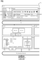
- the only figure shows a functional diagram of a process control system for controlling a process with an operator station client and with an operator station server with indicated software architecture for implementing the method according to the invention.
- the figure shows a functional diagram of parts of a process control system PL for controlling a technical process or a production process in a technical installation.
- the technical plant can be a plant from the process industry, such as a chemical, pharmaceutical, petrochemical plant or a plant from the food and beverages industry. It can also be a facility for the production of goods, such as a factory with production lines.
- the process control system usually includes sensors for determining measured values and various actuators (not shown here).
- the control system includes so-called process or production-related components such as automation devices that are used to control the actuators or sensors.
- the control system has, among other things, means for operating and monitoring as well as means for visualizing the technical system and means for engineering.
- the term control system also includes other computing units for more complex regulations and systems for data storage and data processing.
- a process control system which essentially comprises an operator control and monitoring system with its components, which in the present exemplary embodiment includes an operator station client OS_C (hereinafter abbreviated as OS client), two operator station servers OS_S1 and OS_S2 ( hereinafter abbreviated as OS Server).
- the process control system PL can of course have a large number of OS clients, OS servers and automation devices AS, field devices (not shown), etc.
- the automation devices are connected to the OS servers on the one hand via a plant bus PB, which is usually in the form of an Industrial Ethernet bus, and on the other hand to decentralized peripherals via at least one other bus (not shown here), to which a large number of field devices (sensors, actuators ) are connected.
- PB which is usually in the form of an Industrial Ethernet bus
- decentralized peripherals via at least one other bus (not shown here), to which a large number of field devices (sensors, actuators ) are connected.
- the OS client OS_C exchanges information and data with the OS servers OS_S1 and OS_S2 via a further bus system TB, which is referred to here as a terminal bus.
- the process control system is often designed in such a way that it has at least one additional component such as an engineering workstation (not shown here).
- This is a computer or server that is connected to at least one of the communication systems TB and PB for data transmission, and which is also accessed via a client of the operating and monitoring system, which includes at least one OS server and at least one OS client. can be accessed. If required, further computers or servers can be connected to the communication systems TB and PB.
- the figure also shows parts of the software architecture for implementing the method according to the invention in a simplified form.
- a large number of functions for generating plant images and other displays are shown in the OS server as software blocks or software components (here in the form of rectangles, abbreviated to SW components).
- various displays of a graphical user interface UI of the process control system PL are shown on the OS client.
- a so-called picture hierarchy DH is shown next to a group alarm display GA on the left-hand display of the graphical user interface.
- the image hierarchy DH is of a User created using a suitable software of an engineering system not shown here of the process control system during the engineering phase and represents a technological view of the system to be controlled. Structured nodes are entered or stored there, which are linked to system images, eg "Dosage”.
- the respective system images can be opened online, i.e. during the process control, in that an operator selects the corresponding system image node of the image hierarchy for process monitoring or clicks with a "mouse", whereby the system image associated with the selected system node is opened and displayed on the OS client is displayed.
- a plant image may include a graphical icon, such as a tank or pump, and a block icon associated with a process object, where the block icon is intended for process observation and displays current process values, parameters, and alarm flags of that process object during process control.
- the block symbols in plant pictures can be made dynamic by process values of process objects that are located in the process image of another OS server than the one on which the plant picture itself is located.
- the component D of the OS server OS_S1 is used in a first step to determine whether another OS server of the process control system PL has failed.
- Component D communicates with all other OS servers and distributes any information from a first OS server to all OS servers of the process control system and also receives corresponding information back on request (query).
- Component D can thus also determine the distribution of the process objects on other OS servers. Needed a system image stored in the process image PI of OS_S1 a process object from a process image of another OS server, it requests the required process object via component D.
- Component D in turn ensures that the process image PI of the first OS server can access the process object PO of the other OS server.
- the process image PI of an OS server is a kind of database in which all data such as process values or alarms of the process objects are managed, which are received while the technical system is running.
- the computer-implemented process objects are each assigned to a technical object of the technical installation and are correspondingly operatively connected to it.
- the process object POi in the figure is labeled "PO:PID1" and has a number of associated parameters labeled "Pval”, "Alarm 1", “Alarm 2" and so on in the figure.
- the alarms of the process objects are still functionally connected to the software component of the alarm manager AM shown in the figure, which in the exemplary embodiment shown is connected to the process image PI on the one hand and to the distribution component D on the other.
- the alarm manager or the alarm management component AM queries the process image PI either in a time-dependent or event-driven manner in order to determine whether an alarm status of a process object that is assigned to its own server, here the OS server OS_S1, has changed.
- the alarm manager AM also logs on to the distribution component D in order to be able to take alarms from process objects from other OS servers into account. If a login fails (OS server not available) or if a running login is rejected (OS server not available), then even if the plant image is opened, no operator control or monitoring can take place for the process objects concerned.
- the alarm management component AM checks whether system images are stored on the first OS server OS_S1 that contain process objects from the process image of the failed server (OS_S2) and which system images are affected by the server failure.
- a display alarm status tag also referred to as a DAS tag.
- the tag used in this invention is a complex data structure that allows additional properties or attributes to be assigned to a data element to fulfill a specific purpose.
- a display alarm status tag (DAS tag) is created for each plant image in the process image of an OS server, which represents the alarm status of the respective plant image. If an alarm of a process object occurs (or changes its status), the software subcomponent Display Alarm Status DAS of the alarm management component AM assigns this status to a defined system image - the system image in which the block symbol of the process object that generated the alarm is located located.
- the software sub-component Display Alarm Status DAS ensures that all alarms of the process objects in the system image affected by the server failure are received and only the alarm with the highest priority or the one that has a current time stamp and is not acknowledged is in a Display Alarm Status (DAS) tag configured for the system image (e.g. DAS: Dosage in FIG for system image "Dosage").
- DAS Display Alarm Status
- DAS tag is created for each system image according to a defined addressing convention.
- the Display Alarm Status (DAS) tag is therefore expanded to include status information and linked to the system images.
- the status information is the alarm status for a restricted Operation and monitoring when distributed process objects are lost.
- the alarm management component triggers an operator alarm P, which provides information about the restricted operation of the affected plant image.
- the operator alarm is an alarm of a new alarm class P introduced for this purpose: "partially operable plant display” or "restricted operation”. This alarm is configurable and can be given specific properties (e.g. flashing pink).
- the alarm for reporting restricted operation and monitoring is automatically created as a type by the engineering in the process image.
- the alert management component can then create instances of it - i.e. actively trigger the alert - for each problem that has been identified.
- the alarm management component fills in the pre-configured alarm attributes - such as affected process objects in affected plant images.
- the DAS tag which identifies the alarm status of the affected system image
- the software subcomponent Display Alarm Status DAS which manages the alarm status of system images. If the software subcomponent Display Alarm Status DAS receives a new alarm for a process object of the system image, it is compared with the existing DAS tag. Only if the new alarm is of the highest priority or has a current time stamp and is not acknowledged will the DAS tag be overwritten. In this way, the status of the data structure of the DAS tag is always kept up-to-date, so that the operator is in principle informed instantaneously about the restricted operability.
- the software subcomponent Display Alarm Status DAS serves as a tag manager, so to speak, which constantly checks which display alarm status is present.
- the operator alarm P is displayed on the graphical user interface UI of the OS client OS_C in connection with the affected plant picture and the plant pictures for which not all process objects are available are identified.
- the triggered alarm of the new alarm class P is used, for example, to be able to show in a group alarm display (GA in the display hierarchy of OS_C) that operation is restricted for a specific plant image. Since, as described, the Display Alarm Status DAS tags have been expanded to include the alarm status for limited operation and monitoring when distributed process objects are no longer available, a corresponding status can now also be output as shown (P with a pink background) if the affected system image is in of the plant picture hierarchy can only be partially operated and monitored.
- a table can also be output in a message sequence display (MFA in the system image Dosage of OS_C) and from this it can be seen that there are system images that are available but only operated and monitored to a limited extent can be, whereby an expanded context can also be seen in this representation.
- MFA message sequence display
- a visualization service VS is integrated in the OS server OS_S1, via which (visualization) data is transmitted to the OS client OS_C.
- the visualization service is connected to the data sources within the process image PI via the "Alarm DS" and "Tag DS" interfaces.
- the visualization service thus has all the information known about the components of the process image in order to be able to transfer this to a connected OS client for graphic presentation.
- the plant image hierarchy (Display Hierarchy DH_DL) contained in the VS visualization service is responsible for displaying the image hierarchy (Display Hierarchy) on the OS client with all alarm states and logic.
- the visualization service VS also includes the component PO_DL, which is responsible for displaying the process objects POi. Block symbols belonging to the process objects are shown in the plant image (not included in the figure), with the block symbols being provided for process monitoring in order to display current process values and parameters during the process control.
- the affected system screens which can therefore only be operated and monitored in part, can be determined individually and also individually marked, so that instructions can be introduced for operators at several points in an OS client.
- the restricted operation and monitoring can also be tracked historically, which is of great importance for subsequent investigations into dangerous situations.
Claims (10)
- Procédé de détection d'une commande restreinte et d'observation d'une installation technique, dans lequel on commande un processus au moyen d'un système (PL) de conduite de processus, dans lequel le système de conduite de processus a au moins deux operators station server (OS_S1, OS_S2) et au moins un operator station client (OS_C), et des objets (POi) de processus, reliés au processus, sont répartis sur des représentations (PI) de processus d'operator station server (OS_S1, OS_S2) différents du système (PL) de conduite de processus et, pour l'observation de processus, il est prévu une surface (UI) d'utilisateur graphique sur l'operator station client (OS_C) pour l'indication d'images de l'installation par de symboles appartenant aux objets (POi) de processus,
caractérisé- en ce que, au moyen d'un composant (D) d'un premier operator station server (OS_S1), on détermine si un autre operator station server (OS_S2) du système (PL) de conduite de processus est défaillant,- en ce qu'on annonce une défaillance de ce server (OS_S2) à un composant (AM) de gestion d'alerte au moins du premier des operators station server (OS_S1),- en ce que le composant (AM) de gestion d'alerte contrôle s'il est déposé, sur le premier operator station server (OS_S1), des images de l'installation, qui contiennent des objets de processus de la représentation de processeur du server (OS_S2) défaillant et les images de l'installation, qui sont concernées par la défaillance du server,- en ce que, dans ce cas, on déclenche une alerte (P) de commande, qui donne de l'information sur la commande restreinte de l'image concernée de l'installation,- en ce que, au moyen d'un composant (DAS), qui gère un statut d'alerte d'image de l'installation, dans la représentation (PI) de processus du premier operator station server (OS_S1), on met à jour un jour, qui caractérise un statut d'alerte de l'image concernée de l'installation, et- en ce que, en liaison avec l'image concernée de l'installation, on indique l'alerte (P) de commande sur la surface (UI) d'utilisateur graphique de l'operation station client (OS_C). - Procédé suivant la revendication 1,
caractérisé en ce que, pour indiquer l'alerte (P) de commande sur la surface d'utilisateur graphique du client, on annonce le jour mis à jour auprès d'un service (VS) de visualisation par l'intermédiaire d'une interface (Tag_DS) de jour, et on prend en compte, comme alerte de classe propre, au moyen du composant display-hierarchie (DH_DL), l'alerte (P) de commande dans toutes les indications. - Procédé suivant la revendication 1 ou 2,
caractérisé en ce que l'alerte de commande est configurable. - Procédé suivant la revendication 1 ou 2,
caractérisé en ce que l'on indique l'alerte de commande dans une indication distincte ou l'indication de l'alerte de commande s'effectue ensemble avec des alertes de processus dans des indications d'alerte en groupe ou dans des indications successives de messages. - Procédé suivant l'une des revendications précédentes,
caractérisé en ce que la mise à jour du jour du statut d'alerte de l'image concernée de l'installation dans la représentation de processus s'effectue pour le temps de marche du système de conduit en temps réel ou avec chaque cadence ou d'une manière commandée par un événement. - Procédé suivant l'une des revendications précédentes,
caractérisé en ce que l'on met en mémoire un état du jour en fonction du temps, pour déterminer des laps de temps dans lesquels il y a une possibilité de commande restreinte. - Procédé suivant la revendication 6,
caractérisé en ce qu'on met en mémoire supplémentairement les objets de processus, qui ont provoqué une possibilité de commande restreinte et/ou on établit des statistiques sur les objets de processus, les représentations de processus et les servers, qui ont provoqués une possibilité de commande restreinte. - Système de commande et d'observation d'un système de conduite de processus, qui commande un processus dans une installation technique, comprenant au moins un client (OS_C) et au moins deux servers (OS_S1, OS_S2, ...), qui sont reliés les uns aux autres par au moins un moyen (TB) de communication, dans lequel chaque server (OS) a une représentation de processus, qui contient des objets (POi) de processus reliés au processus,- il est prévu, pour l'observation de processus, une surface (UI) d'utilisateur graphique sur l'operator station client (OS_C), pour l'indication d'images de l'installation par des symboles (Block) appartenant aux objets de processus,
caractérisé- en ce qu'un premier composant (D) du premier operator station server (OS_S1) est constitué pour déterminer si un autre operator station server (OS_S2) du système (PL) de conduite de processus est défaillant,- en ce qu'un composant (AM) de gestion d'alerte du premier operator station server (OS_S1) est relié au premier composant et est constitué pour, après l'information sur la défaillance de ce server (OS_S2), contrôler s'il est déposé sur le premier operator station server (OS_S1) des images de l'installation, qui contiennent des objets de processus de la représentation de processus du server (OS_S2) défaillant et lesquelles images de l'installation sont ainsi concernées par la défaillance du server, et dans ce cas, pour déclencher une alerte (P) configurable de commande, qui donne de l'information sur la commande restreinte de l'image concernée de l'installation,- en ce qu'un autre composant (DAS), qui gère un statut d'alerte d'image de l'installation est relié au composant de gestion d'alerte et est constitué pour mettre à jour, dans la représentation (PI) de processus, un jour du statut d'alerte de l'image concernée de l'installation et pour provoquer, par un service de visualisation que, en liaison avec l'image concernée de l'installation, l'alerte (P) de commande soit indiquée sur la surface (UI) d'utilisateur graphique de l'operator station client (OS_C). - Système de commande et d'observation suivant la revendication 8,
caractérisé en ce que l'operator station server (OS_S1) contient d'autres composants, qui sont constitués pour effectuer les stades du procédé suivant les revendications 2 à 7. - Système de conduite de processus pour la commande d'un processus dans une installation technique, qui a un système de commande et d'observation suivant la revendication 8 ou 9.
Priority Applications (3)
| Application Number | Priority Date | Filing Date | Title |
|---|---|---|---|
| EP21176905.4A EP4099114B1 (fr) | 2021-05-31 | 2021-05-31 | Procédé de détection d'une commande restreinte et d'observation d'une installation technique, système de commande et d'observation et système de contrôle de processus |
| US17/826,270 US11860611B2 (en) | 2021-05-31 | 2022-05-27 | Method for identifying a limited operator control and monitoring of a technical plant, operator control and monitoring system and process control system |
| CN202210600652.3A CN115480521A (zh) | 2021-05-31 | 2022-05-30 | 用于识别技术设施的受限的操作和监控的方法、操作系统和监控系统和过程控制系统 |
Applications Claiming Priority (1)
| Application Number | Priority Date | Filing Date | Title |
|---|---|---|---|
| EP21176905.4A EP4099114B1 (fr) | 2021-05-31 | 2021-05-31 | Procédé de détection d'une commande restreinte et d'observation d'une installation technique, système de commande et d'observation et système de contrôle de processus |
Publications (3)
| Publication Number | Publication Date |
|---|---|
| EP4099114A1 EP4099114A1 (fr) | 2022-12-07 |
| EP4099114C0 EP4099114C0 (fr) | 2023-07-19 |
| EP4099114B1 true EP4099114B1 (fr) | 2023-07-19 |
Family
ID=76197367
Family Applications (1)
| Application Number | Title | Priority Date | Filing Date |
|---|---|---|---|
| EP21176905.4A Active EP4099114B1 (fr) | 2021-05-31 | 2021-05-31 | Procédé de détection d'une commande restreinte et d'observation d'une installation technique, système de commande et d'observation et système de contrôle de processus |
Country Status (3)
| Country | Link |
|---|---|
| US (1) | US11860611B2 (fr) |
| EP (1) | EP4099114B1 (fr) |
| CN (1) | CN115480521A (fr) |
Families Citing this family (2)
| Publication number | Priority date | Publication date | Assignee | Title |
|---|---|---|---|---|
| EP4312418A1 (fr) * | 2022-07-29 | 2024-01-31 | Abb Schweiz Ag | Procédé de sélection automatique de serveurs |
| US11908304B1 (en) * | 2022-10-21 | 2024-02-20 | Eurotherm Limited | Systems and methods for managing unprocessed alarms in alarm systems |
Family Cites Families (10)
| Publication number | Priority date | Publication date | Assignee | Title |
|---|---|---|---|---|
| US7209859B2 (en) * | 2002-03-02 | 2007-04-24 | Linxberg Technology, Llc | Method and apparatus for sequentially collecting and analyzing real time data with interactive monitoring |
| JP2007536634A (ja) * | 2004-05-04 | 2007-12-13 | フィッシャー−ローズマウント・システムズ・インコーポレーテッド | プロセス制御システムのためのサービス指向型アーキテクチャ |
| US7818615B2 (en) * | 2004-09-16 | 2010-10-19 | Invensys Systems, Inc. | Runtime failure management of redundantly deployed hosts of a supervisory process control data acquisition facility |
| US20130100136A1 (en) * | 2011-10-24 | 2013-04-25 | Kim Ordean Van Camp | Sparkline presentations of process control system alarms |
| EP3104242A1 (fr) * | 2015-06-12 | 2016-12-14 | Siemens Aktiengesellschaft | Systeme de commande et procede pour la évaluation de la communication dans un processus technique |
| WO2018005815A1 (fr) * | 2016-06-30 | 2018-01-04 | Carrier Corporation | Système et procédé de surveillance d'alarme collaborative |
| EP3276437A1 (fr) * | 2016-07-27 | 2018-01-31 | Siemens Aktiengesellschaft | Procédé d'exploitation d'un système d'automatisation, système de commande et d'observation et système d'automatisation |
| EP3480672B1 (fr) * | 2017-11-06 | 2020-02-19 | Siemens Aktiengesellschaft | Procédé de détection et d'affichage d'accès d'opérateur à des objets de traitement ainsi que système d'exploitation |
| EP3598255B1 (fr) * | 2018-07-17 | 2022-01-26 | Siemens Aktiengesellschaft | Système pourvu d'opérateurs serveurs et d'opérateurs clients |
| EP3805882B1 (fr) * | 2019-10-10 | 2022-06-08 | Siemens Aktiengesellschaft | Système de guidage pour une installation technique pourvu de diagramme de courbe de tendance |
-
2021
- 2021-05-31 EP EP21176905.4A patent/EP4099114B1/fr active Active
-
2022
- 2022-05-27 US US17/826,270 patent/US11860611B2/en active Active
- 2022-05-30 CN CN202210600652.3A patent/CN115480521A/zh active Pending
Also Published As
| Publication number | Publication date |
|---|---|
| EP4099114C0 (fr) | 2023-07-19 |
| CN115480521A (zh) | 2022-12-16 |
| US20220382260A1 (en) | 2022-12-01 |
| US11860611B2 (en) | 2024-01-02 |
| EP4099114A1 (fr) | 2022-12-07 |
Similar Documents
| Publication | Publication Date | Title |
|---|---|---|
| DE102004042813B4 (de) | Alarmmanagementsystem | |
| EP4099114B1 (fr) | Procédé de détection d'une commande restreinte et d'observation d'une installation technique, système de commande et d'observation et système de contrôle de processus | |
| EP3876046B1 (fr) | Annotation de retour des sélections opérateur | |
| EP3953774B1 (fr) | Dispositif pour la détection de causes d'alarmes | |
| EP3495903B1 (fr) | Procédé de commande et de surveillance d'une installation technique à commander ainsi que système d'exploitation | |
| EP3623891A1 (fr) | Hiérarchies d'images pouvant être individualisées pour un système de conduite d'une installation technique | |
| EP0645711A1 (fr) | Procédé d'opération d'un dispositif d'affichage et dispositifs pour la mise en oeuvre de ce procédé | |
| EP3637205A1 (fr) | Déclenchement de l'image sur une station client de l'opérateur | |
| WO2020144305A1 (fr) | Entrée de boucle d'alarme d'affichages de séquences de message | |
| EP3598255B1 (fr) | Système pourvu d'opérateurs serveurs et d'opérateurs clients | |
| WO2020064712A1 (fr) | Procédé pour l'amélioration de la priorisation de messages, composant logiciel, système de commande et d'observation et système d'automatisation | |
| EP3637211B1 (fr) | Procédé de fonctionnement d'une installation ainsi qu'une installation | |
| EP4261629A1 (fr) | Système de commande pour une installation technique et procédé de fonctionnement | |
| EP4123401A1 (fr) | Représentation granulaire de l'état de charge des éléments basés sur le web d'un système de commande pour une installation technique | |
| EP4290326A1 (fr) | Système de commande pour une installation technique et procédé de fonctionnement | |
| EP4030247B1 (fr) | Annotation de retour des réductions de charge des clients | |
| WO2023222384A1 (fr) | Système de commande pour une installation technique, et procédé de fonctionnement | |
| EP4137900A1 (fr) | Conteneur associé à une alarme dans les photos d'installation des installations techniques | |
| WO2023175113A1 (fr) | Système de commande pour installation technique et procédé de fonctionnement | |
| WO2023170206A1 (fr) | Système de commande pour installation technique et procédé de fonctionnement | |
| WO2023057364A1 (fr) | Création contextualisée et collaborative de sauvegardes d'écrans dans un système de commande pour une installation technique | |
| EP4354233A1 (fr) | Système de guidage pour une installation technique et procédé de fonctionnement | |
| DE19818041A9 (de) | Verfahren zur Erzeugung einer Oberfläche zum Bedienen und Beobachten von Leitsystemen | |
| EP4089489A1 (fr) | Système de commande pour une installation technique | |
| EP4332699A1 (fr) | Système de guidage assisté d'opérateur pour une installation technique et procédé de fonctionnement |
Legal Events
| Date | Code | Title | Description |
|---|---|---|---|
| PUAI | Public reference made under article 153(3) epc to a published international application that has entered the european phase |
Free format text: ORIGINAL CODE: 0009012 |
|
| STAA | Information on the status of an ep patent application or granted ep patent |
Free format text: STATUS: REQUEST FOR EXAMINATION WAS MADE |
|
| 17P | Request for examination filed |
Effective date: 20220518 |
|
| AK | Designated contracting states |
Kind code of ref document: A1 Designated state(s): AL AT BE BG CH CY CZ DE DK EE ES FI FR GB GR HR HU IE IS IT LI LT LU LV MC MK MT NL NO PL PT RO RS SE SI SK SM TR |
|
| GRAP | Despatch of communication of intention to grant a patent |
Free format text: ORIGINAL CODE: EPIDOSNIGR1 |
|
| STAA | Information on the status of an ep patent application or granted ep patent |
Free format text: STATUS: GRANT OF PATENT IS INTENDED |
|
| RIC1 | Information provided on ipc code assigned before grant |
Ipc: G05B 23/02 20060101AFI20230218BHEP |
|
| INTG | Intention to grant announced |
Effective date: 20230310 |
|
| GRAS | Grant fee paid |
Free format text: ORIGINAL CODE: EPIDOSNIGR3 |
|
| GRAA | (expected) grant |
Free format text: ORIGINAL CODE: 0009210 |
|
| STAA | Information on the status of an ep patent application or granted ep patent |
Free format text: STATUS: THE PATENT HAS BEEN GRANTED |
|
| AK | Designated contracting states |
Kind code of ref document: B1 Designated state(s): AL AT BE BG CH CY CZ DE DK EE ES FI FR GB GR HR HU IE IS IT LI LT LU LV MC MK MT NL NO PL PT RO RS SE SI SK SM TR |
|
| REG | Reference to a national code |
Ref country code: GB Ref legal event code: FG4D Free format text: NOT ENGLISH |
|
| REG | Reference to a national code |
Ref country code: CH Ref legal event code: EP |
|
| REG | Reference to a national code |
Ref country code: DE Ref legal event code: R096 Ref document number: 502021001029 Country of ref document: DE |
|
| REG | Reference to a national code |
Ref country code: IE Ref legal event code: FG4D Free format text: LANGUAGE OF EP DOCUMENT: GERMAN |
|
| U01 | Request for unitary effect filed |
Effective date: 20230720 |
|
| U07 | Unitary effect registered |
Designated state(s): AT BE BG DE DK EE FI FR IT LT LU LV MT NL PT SE SI Effective date: 20230726 |
|
| REG | Reference to a national code |
Ref country code: LT Ref legal event code: MG9D |
|
| PG25 | Lapsed in a contracting state [announced via postgrant information from national office to epo] |
Ref country code: GR Free format text: LAPSE BECAUSE OF FAILURE TO SUBMIT A TRANSLATION OF THE DESCRIPTION OR TO PAY THE FEE WITHIN THE PRESCRIBED TIME-LIMIT Effective date: 20231020 |
|
| PG25 | Lapsed in a contracting state [announced via postgrant information from national office to epo] |
Ref country code: IS Free format text: LAPSE BECAUSE OF FAILURE TO SUBMIT A TRANSLATION OF THE DESCRIPTION OR TO PAY THE FEE WITHIN THE PRESCRIBED TIME-LIMIT Effective date: 20231119 |
|
| PG25 | Lapsed in a contracting state [announced via postgrant information from national office to epo] |
Ref country code: RS Free format text: LAPSE BECAUSE OF FAILURE TO SUBMIT A TRANSLATION OF THE DESCRIPTION OR TO PAY THE FEE WITHIN THE PRESCRIBED TIME-LIMIT Effective date: 20230719 Ref country code: NO Free format text: LAPSE BECAUSE OF FAILURE TO SUBMIT A TRANSLATION OF THE DESCRIPTION OR TO PAY THE FEE WITHIN THE PRESCRIBED TIME-LIMIT Effective date: 20231019 Ref country code: IS Free format text: LAPSE BECAUSE OF FAILURE TO SUBMIT A TRANSLATION OF THE DESCRIPTION OR TO PAY THE FEE WITHIN THE PRESCRIBED TIME-LIMIT Effective date: 20231119 Ref country code: HR Free format text: LAPSE BECAUSE OF FAILURE TO SUBMIT A TRANSLATION OF THE DESCRIPTION OR TO PAY THE FEE WITHIN THE PRESCRIBED TIME-LIMIT Effective date: 20230719 Ref country code: GR Free format text: LAPSE BECAUSE OF FAILURE TO SUBMIT A TRANSLATION OF THE DESCRIPTION OR TO PAY THE FEE WITHIN THE PRESCRIBED TIME-LIMIT Effective date: 20231020 |
|
| PG25 | Lapsed in a contracting state [announced via postgrant information from national office to epo] |
Ref country code: PL Free format text: LAPSE BECAUSE OF FAILURE TO SUBMIT A TRANSLATION OF THE DESCRIPTION OR TO PAY THE FEE WITHIN THE PRESCRIBED TIME-LIMIT Effective date: 20230719 |