EP4099114B1 - Method for detecting a restricted operation and observation of a technical installation, operating and monitoring system and process control system - Google Patents
Method for detecting a restricted operation and observation of a technical installation, operating and monitoring system and process control system Download PDFInfo
- Publication number
- EP4099114B1 EP4099114B1 EP21176905.4A EP21176905A EP4099114B1 EP 4099114 B1 EP4099114 B1 EP 4099114B1 EP 21176905 A EP21176905 A EP 21176905A EP 4099114 B1 EP4099114 B1 EP 4099114B1
- Authority
- EP
- European Patent Office
- Prior art keywords
- operator
- alarm
- server
- plant
- image
- Prior art date
- Legal status (The legal status is an assumption and is not a legal conclusion. Google has not performed a legal analysis and makes no representation as to the accuracy of the status listed.)
- Active
Links
- 238000000034 method Methods 0.000 title claims description 150
- 238000012544 monitoring process Methods 0.000 title claims description 38
- 238000004886 process control Methods 0.000 title claims description 35
- 238000009434 installation Methods 0.000 title description 4
- 230000008569 process Effects 0.000 claims description 126
- 238000012800 visualization Methods 0.000 claims description 10
- 238000004891 communication Methods 0.000 claims description 4
- 238000007726 management method Methods 0.000 description 10
- 238000004519 manufacturing process Methods 0.000 description 7
- 230000008859 change Effects 0.000 description 4
- 230000001276 controlling effect Effects 0.000 description 3
- 238000009826 distribution Methods 0.000 description 3
- 230000006870 function Effects 0.000 description 3
- 230000001960 triggered effect Effects 0.000 description 3
- 238000010586 diagram Methods 0.000 description 2
- 238000010327 methods by industry Methods 0.000 description 2
- 238000012545 processing Methods 0.000 description 2
- 101000609957 Homo sapiens PTB-containing, cubilin and LRP1-interacting protein Proteins 0.000 description 1
- 102100039157 PTB-containing, cubilin and LRP1-interacting protein Human genes 0.000 description 1
- 241001613929 Staphylococcus phage ROSA Species 0.000 description 1
- 239000008186 active pharmaceutical agent Substances 0.000 description 1
- 230000003044 adaptive effect Effects 0.000 description 1
- 230000002730 additional effect Effects 0.000 description 1
- 230000008901 benefit Effects 0.000 description 1
- 235000013361 beverage Nutrition 0.000 description 1
- 230000005540 biological transmission Effects 0.000 description 1
- 238000004364 calculation method Methods 0.000 description 1
- 238000013500 data storage Methods 0.000 description 1
- 230000007547 defect Effects 0.000 description 1
- 230000001419 dependent effect Effects 0.000 description 1
- 238000001514 detection method Methods 0.000 description 1
- 238000011161 development Methods 0.000 description 1
- 230000018109 developmental process Effects 0.000 description 1
- 230000000694 effects Effects 0.000 description 1
- 230000036541 health Effects 0.000 description 1
- 238000011835 investigation Methods 0.000 description 1
- 238000012423 maintenance Methods 0.000 description 1
- 230000002093 peripheral effect Effects 0.000 description 1
- 238000000275 quality assurance Methods 0.000 description 1
- 230000001105 regulatory effect Effects 0.000 description 1
- 230000000717 retained effect Effects 0.000 description 1
- 230000003068 static effect Effects 0.000 description 1
- 239000000126 substance Substances 0.000 description 1
- 230000036962 time dependent Effects 0.000 description 1
- 238000012546 transfer Methods 0.000 description 1
Images
Classifications
-
- G—PHYSICS
- G05—CONTROLLING; REGULATING
- G05B—CONTROL OR REGULATING SYSTEMS IN GENERAL; FUNCTIONAL ELEMENTS OF SUCH SYSTEMS; MONITORING OR TESTING ARRANGEMENTS FOR SUCH SYSTEMS OR ELEMENTS
- G05B19/00—Programme-control systems
- G05B19/02—Programme-control systems electric
- G05B19/418—Total factory control, i.e. centrally controlling a plurality of machines, e.g. direct or distributed numerical control [DNC], flexible manufacturing systems [FMS], integrated manufacturing systems [IMS], computer integrated manufacturing [CIM]
- G05B19/41865—Total factory control, i.e. centrally controlling a plurality of machines, e.g. direct or distributed numerical control [DNC], flexible manufacturing systems [FMS], integrated manufacturing systems [IMS], computer integrated manufacturing [CIM] characterised by job scheduling, process planning, material flow
-
- G—PHYSICS
- G05—CONTROLLING; REGULATING
- G05B—CONTROL OR REGULATING SYSTEMS IN GENERAL; FUNCTIONAL ELEMENTS OF SUCH SYSTEMS; MONITORING OR TESTING ARRANGEMENTS FOR SUCH SYSTEMS OR ELEMENTS
- G05B23/00—Testing or monitoring of control systems or parts thereof
- G05B23/02—Electric testing or monitoring
- G05B23/0205—Electric testing or monitoring by means of a monitoring system capable of detecting and responding to faults
- G05B23/0259—Electric testing or monitoring by means of a monitoring system capable of detecting and responding to faults characterized by the response to fault detection
- G05B23/0267—Fault communication, e.g. human machine interface [HMI]
-
- G—PHYSICS
- G05—CONTROLLING; REGULATING
- G05B—CONTROL OR REGULATING SYSTEMS IN GENERAL; FUNCTIONAL ELEMENTS OF SUCH SYSTEMS; MONITORING OR TESTING ARRANGEMENTS FOR SUCH SYSTEMS OR ELEMENTS
- G05B19/00—Programme-control systems
- G05B19/02—Programme-control systems electric
- G05B19/418—Total factory control, i.e. centrally controlling a plurality of machines, e.g. direct or distributed numerical control [DNC], flexible manufacturing systems [FMS], integrated manufacturing systems [IMS], computer integrated manufacturing [CIM]
- G05B19/41885—Total factory control, i.e. centrally controlling a plurality of machines, e.g. direct or distributed numerical control [DNC], flexible manufacturing systems [FMS], integrated manufacturing systems [IMS], computer integrated manufacturing [CIM] characterised by modeling, simulation of the manufacturing system
-
- G—PHYSICS
- G05—CONTROLLING; REGULATING
- G05B—CONTROL OR REGULATING SYSTEMS IN GENERAL; FUNCTIONAL ELEMENTS OF SUCH SYSTEMS; MONITORING OR TESTING ARRANGEMENTS FOR SUCH SYSTEMS OR ELEMENTS
- G05B19/00—Programme-control systems
- G05B19/02—Programme-control systems electric
- G05B19/04—Programme control other than numerical control, i.e. in sequence controllers or logic controllers
- G05B19/042—Programme control other than numerical control, i.e. in sequence controllers or logic controllers using digital processors
- G05B19/0428—Safety, monitoring
-
- G—PHYSICS
- G05—CONTROLLING; REGULATING
- G05B—CONTROL OR REGULATING SYSTEMS IN GENERAL; FUNCTIONAL ELEMENTS OF SUCH SYSTEMS; MONITORING OR TESTING ARRANGEMENTS FOR SUCH SYSTEMS OR ELEMENTS
- G05B2219/00—Program-control systems
- G05B2219/10—Plc systems
- G05B2219/15—Plc structure of the system
- G05B2219/15006—Set configuration from master control station
-
- G—PHYSICS
- G05—CONTROLLING; REGULATING
- G05B—CONTROL OR REGULATING SYSTEMS IN GENERAL; FUNCTIONAL ELEMENTS OF SUCH SYSTEMS; MONITORING OR TESTING ARRANGEMENTS FOR SUCH SYSTEMS OR ELEMENTS
- G05B2219/00—Program-control systems
- G05B2219/20—Pc systems
- G05B2219/25—Pc structure of the system
- G05B2219/25202—Internet, tcp-ip, web server : see under S05B219-40
-
- G—PHYSICS
- G05—CONTROLLING; REGULATING
- G05B—CONTROL OR REGULATING SYSTEMS IN GENERAL; FUNCTIONAL ELEMENTS OF SUCH SYSTEMS; MONITORING OR TESTING ARRANGEMENTS FOR SUCH SYSTEMS OR ELEMENTS
- G05B2219/00—Program-control systems
- G05B2219/20—Pc systems
- G05B2219/26—Pc applications
- G05B2219/2609—Process control
-
- G—PHYSICS
- G05—CONTROLLING; REGULATING
- G05B—CONTROL OR REGULATING SYSTEMS IN GENERAL; FUNCTIONAL ELEMENTS OF SUCH SYSTEMS; MONITORING OR TESTING ARRANGEMENTS FOR SUCH SYSTEMS OR ELEMENTS
- G05B2219/00—Program-control systems
- G05B2219/30—Nc systems
- G05B2219/32—Operator till task planning
- G05B2219/32339—Object oriented modeling, design, analysis, implementation, simulation language
Definitions
- the invention relates to a method for operating and monitoring a technical system to be controlled according to the preamble of claim 1.
- the invention also relates to an operating and monitoring system according to the preamble of claim 8 for carrying out the method and a correspondingly suitable process control system.
- system images are used, which represent the relationships - in particular between the individual functional units or components of the technical system - in an abstract manner.
- the plant images are usually displayed on a client of a process control system.
- Plant screens are made up of various operating and display elements. These include: static symbols (e.g. lines, rectangles, etc.), dynamized symbols (e.g.
- process objects which are localized in a process image (PI, see figure) of an operator station server (OS_S, see figure) of the process control system are.
- a process object corresponds to a functional component or unit of a process engineering plant or production plant and is always linked to a measuring point.
- CFC Continuous Function Charts
- the computer-implemented process object localized in the process image is thus always assigned to a technical object of the technical system and is actively connected to it.
- the term "dynamized” is used here to represent a change in the process values over time. This change can either be caused by the process itself (temperature reading of a container changes.) or by the operator (input: "Heat the container to a temperature of 100°C.”). As a result of each change, the system image must be updated and redrawn.
- the process objects can be distributed in the process images of different OS servers. This means that the block symbols of the plant pictures are also made dynamic by process values of process objects that are localized in the process image of another operator station server than the one on which the plant picture itself is located. If an operator station server fails, for example due to a defect, maintenance or due to the loading of configuration data, and this operator station server contains process values from process objects to dynamize a plant image of another operator station server, the operation and monitoring of this plant image is partially available for the period of the failure restricted. Although have appropriate Diagnostic information in message sequence displays indicates the failure of operator station servers, but it is not clear to an operator what effects this has on his operation and monitoring in the context of the plant images and process objects accessible to him.
- the plant images that are located on the failed operator station servers are also omitted from the corresponding navigation hierarchies.
- the system images of the available operator station servers are retained, but can only be used to a limited extent, since they use process values of process objects for dynamization that are contained in the process image of a deleted operator station server.
- process values of process objects for dynamization that are contained in the process image of a deleted operator station server.
- each OS server keeps a "service configuration" table that stores the following information for each subsystem: the server name / IP address of the OS server that the process image of each sub-system and maintains how many process objects are contained in the process image of the respective sub-system, health index for the status of the other OS servers with regard to memory utilization, CPU utilization, temperature of the components and aspects of the hardware and software as well as the mode of the respective OS server (active passive).
- the entries in this "Service Configuration" table are taken into account when selecting preferred servers in order to minimize the overall cross-communication between the OS servers.
- the invention is therefore based on the object of specifying a method by means of which efficient and, above all, reliable operation and monitoring of a technical installation to be controlled is achieved, which allows reliable process management. Furthermore, an operating and monitoring system that is particularly suitable for carrying out the method for a process control system and a corresponding process control system are to be specified.
- a method is presented, based on which a detection of a partially restricted operation and observation of a technical system in which a technical Process is controlled by a process control system is made possible.
- the process control system has at least two operator station servers and at least one operator station client, with process objects connected to the process being distributed in process images of different operator station servers of the process control system.
- a graphic user interface is provided on the operator station client for process monitoring to display plant images with symbols belonging to the process objects.
- the invention is characterized by the following method steps: A component of a first operator station server is used to determine whether another operator station server of the process control system has failed. A failure of this server is reported to an alarm management component of the first operator station server. The alarm management component checks whether system images are stored on the first operator station server that contain process objects from the process image of the failed server and which system images are affected by the server failure. In this case, an operator alarm informing about the restricted operation of the affected system image is triggered. Using a component that manages an alarm status of plant images, a separate tag that identifies the alarm status of the affected plant image is updated in the process image of the first server and the operator alarm is displayed on the graphical user interface of the operator station client in connection with the affected plant image.
- the advantage of the invention is that if process objects are lost due to a server failure of the control system, the affected system images, which can therefore only be partially operated and monitored, are individually determined using the inventive method and also individually identified. In this way, an operator can immediately see during process control which of his available system images are currently point in time can only be partially operated and monitored without having to explicitly select them.
- the operator of the control system is informed and alerted by the triggering of the operating alarm, which means that the operation and monitoring of the system remains reliable, and the technical system also remains in a safe state, although a potentially dangerous situation could arise due to the server failure.
- the updated tag is registered with the visualization service via a tag interface to display the operator alarm on the graphical user interface of the client, and the operator alarm is taken into account in all displays as an alarm of its own class by means of the display hierarchy component.
- the display is always up-to-date. This allows a particularly safe operation and monitoring of the technical system.
- the operating alarm can be configured.
- the alarm for reporting restricted operation and monitoring is created as a type by the engineering in the process image.
- the alarm attributes are also defined, such as affected process objects in affected plant images.
- the alarm attributes can be defined arbitrarily. This allows a high degree of flexibility when providing the alarm.
- the operator alarm is displayed in a separate display or the operator alarm is displayed together with process alarms in group alarm displays or message sequence displays. This allows better visibility of the operator alarm. An operator can better recognize the restriction of the operation.
- the tag of the alarm status of the system image in question is updated in the process image during the runtime of the control system in real time or with every cycle or event-controlled. This allows a dynamic and adaptive adjustment of the operation of the technical system. How the operator alarm is to be configured can be specified during engineering.
- the respective status of the Display Alarm Status (DAS) tag is stored as a function of time.
- DAS Display Alarm Status
- periods of time can advantageously be determined in which there is restricted operability. This means that the limited operation and monitoring can also be tracked historically.
- the process objects that caused restricted operability can also be stored and/or statistics about the process objects, process images and servers that caused restricted operability can be created.
- Such extensive context information can be read into a quality assurance tool, for example, and is used to control and record changes that have occurred in processes. In this way, interventions in the operation of the technical system can be traced after the occurrence of an operator alarm.
- the method according to the invention is preferably implemented in software or in a combination of software/hardware, so that the invention also relates to an operating and monitoring system and a process control system which are designed to carry out a method of the type described.
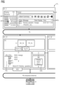
- the only figure shows a functional diagram of a process control system for controlling a process with an operator station client and with an operator station server with indicated software architecture for implementing the method according to the invention.
- the figure shows a functional diagram of parts of a process control system PL for controlling a technical process or a production process in a technical installation.
- the technical plant can be a plant from the process industry, such as a chemical, pharmaceutical, petrochemical plant or a plant from the food and beverages industry. It can also be a facility for the production of goods, such as a factory with production lines.
- the process control system usually includes sensors for determining measured values and various actuators (not shown here).
- the control system includes so-called process or production-related components such as automation devices that are used to control the actuators or sensors.
- the control system has, among other things, means for operating and monitoring as well as means for visualizing the technical system and means for engineering.
- the term control system also includes other computing units for more complex regulations and systems for data storage and data processing.
- a process control system which essentially comprises an operator control and monitoring system with its components, which in the present exemplary embodiment includes an operator station client OS_C (hereinafter abbreviated as OS client), two operator station servers OS_S1 and OS_S2 ( hereinafter abbreviated as OS Server).
- the process control system PL can of course have a large number of OS clients, OS servers and automation devices AS, field devices (not shown), etc.
- the automation devices are connected to the OS servers on the one hand via a plant bus PB, which is usually in the form of an Industrial Ethernet bus, and on the other hand to decentralized peripherals via at least one other bus (not shown here), to which a large number of field devices (sensors, actuators ) are connected.
- PB which is usually in the form of an Industrial Ethernet bus
- decentralized peripherals via at least one other bus (not shown here), to which a large number of field devices (sensors, actuators ) are connected.
- the OS client OS_C exchanges information and data with the OS servers OS_S1 and OS_S2 via a further bus system TB, which is referred to here as a terminal bus.
- the process control system is often designed in such a way that it has at least one additional component such as an engineering workstation (not shown here).
- This is a computer or server that is connected to at least one of the communication systems TB and PB for data transmission, and which is also accessed via a client of the operating and monitoring system, which includes at least one OS server and at least one OS client. can be accessed. If required, further computers or servers can be connected to the communication systems TB and PB.
- the figure also shows parts of the software architecture for implementing the method according to the invention in a simplified form.
- a large number of functions for generating plant images and other displays are shown in the OS server as software blocks or software components (here in the form of rectangles, abbreviated to SW components).
- various displays of a graphical user interface UI of the process control system PL are shown on the OS client.
- a so-called picture hierarchy DH is shown next to a group alarm display GA on the left-hand display of the graphical user interface.
- the image hierarchy DH is of a User created using a suitable software of an engineering system not shown here of the process control system during the engineering phase and represents a technological view of the system to be controlled. Structured nodes are entered or stored there, which are linked to system images, eg "Dosage”.
- the respective system images can be opened online, i.e. during the process control, in that an operator selects the corresponding system image node of the image hierarchy for process monitoring or clicks with a "mouse", whereby the system image associated with the selected system node is opened and displayed on the OS client is displayed.
- a plant image may include a graphical icon, such as a tank or pump, and a block icon associated with a process object, where the block icon is intended for process observation and displays current process values, parameters, and alarm flags of that process object during process control.
- the block symbols in plant pictures can be made dynamic by process values of process objects that are located in the process image of another OS server than the one on which the plant picture itself is located.
- the component D of the OS server OS_S1 is used in a first step to determine whether another OS server of the process control system PL has failed.
- Component D communicates with all other OS servers and distributes any information from a first OS server to all OS servers of the process control system and also receives corresponding information back on request (query).
- Component D can thus also determine the distribution of the process objects on other OS servers. Needed a system image stored in the process image PI of OS_S1 a process object from a process image of another OS server, it requests the required process object via component D.
- Component D in turn ensures that the process image PI of the first OS server can access the process object PO of the other OS server.
- the process image PI of an OS server is a kind of database in which all data such as process values or alarms of the process objects are managed, which are received while the technical system is running.
- the computer-implemented process objects are each assigned to a technical object of the technical installation and are correspondingly operatively connected to it.
- the process object POi in the figure is labeled "PO:PID1" and has a number of associated parameters labeled "Pval”, "Alarm 1", “Alarm 2" and so on in the figure.
- the alarms of the process objects are still functionally connected to the software component of the alarm manager AM shown in the figure, which in the exemplary embodiment shown is connected to the process image PI on the one hand and to the distribution component D on the other.
- the alarm manager or the alarm management component AM queries the process image PI either in a time-dependent or event-driven manner in order to determine whether an alarm status of a process object that is assigned to its own server, here the OS server OS_S1, has changed.
- the alarm manager AM also logs on to the distribution component D in order to be able to take alarms from process objects from other OS servers into account. If a login fails (OS server not available) or if a running login is rejected (OS server not available), then even if the plant image is opened, no operator control or monitoring can take place for the process objects concerned.
- the alarm management component AM checks whether system images are stored on the first OS server OS_S1 that contain process objects from the process image of the failed server (OS_S2) and which system images are affected by the server failure.
- a display alarm status tag also referred to as a DAS tag.
- the tag used in this invention is a complex data structure that allows additional properties or attributes to be assigned to a data element to fulfill a specific purpose.
- a display alarm status tag (DAS tag) is created for each plant image in the process image of an OS server, which represents the alarm status of the respective plant image. If an alarm of a process object occurs (or changes its status), the software subcomponent Display Alarm Status DAS of the alarm management component AM assigns this status to a defined system image - the system image in which the block symbol of the process object that generated the alarm is located located.
- the software sub-component Display Alarm Status DAS ensures that all alarms of the process objects in the system image affected by the server failure are received and only the alarm with the highest priority or the one that has a current time stamp and is not acknowledged is in a Display Alarm Status (DAS) tag configured for the system image (e.g. DAS: Dosage in FIG for system image "Dosage").
- DAS Display Alarm Status
- DAS tag is created for each system image according to a defined addressing convention.
- the Display Alarm Status (DAS) tag is therefore expanded to include status information and linked to the system images.
- the status information is the alarm status for a restricted Operation and monitoring when distributed process objects are lost.
- the alarm management component triggers an operator alarm P, which provides information about the restricted operation of the affected plant image.
- the operator alarm is an alarm of a new alarm class P introduced for this purpose: "partially operable plant display” or "restricted operation”. This alarm is configurable and can be given specific properties (e.g. flashing pink).
- the alarm for reporting restricted operation and monitoring is automatically created as a type by the engineering in the process image.
- the alert management component can then create instances of it - i.e. actively trigger the alert - for each problem that has been identified.
- the alarm management component fills in the pre-configured alarm attributes - such as affected process objects in affected plant images.
- the DAS tag which identifies the alarm status of the affected system image
- the software subcomponent Display Alarm Status DAS which manages the alarm status of system images. If the software subcomponent Display Alarm Status DAS receives a new alarm for a process object of the system image, it is compared with the existing DAS tag. Only if the new alarm is of the highest priority or has a current time stamp and is not acknowledged will the DAS tag be overwritten. In this way, the status of the data structure of the DAS tag is always kept up-to-date, so that the operator is in principle informed instantaneously about the restricted operability.
- the software subcomponent Display Alarm Status DAS serves as a tag manager, so to speak, which constantly checks which display alarm status is present.
- the operator alarm P is displayed on the graphical user interface UI of the OS client OS_C in connection with the affected plant picture and the plant pictures for which not all process objects are available are identified.
- the triggered alarm of the new alarm class P is used, for example, to be able to show in a group alarm display (GA in the display hierarchy of OS_C) that operation is restricted for a specific plant image. Since, as described, the Display Alarm Status DAS tags have been expanded to include the alarm status for limited operation and monitoring when distributed process objects are no longer available, a corresponding status can now also be output as shown (P with a pink background) if the affected system image is in of the plant picture hierarchy can only be partially operated and monitored.
- a table can also be output in a message sequence display (MFA in the system image Dosage of OS_C) and from this it can be seen that there are system images that are available but only operated and monitored to a limited extent can be, whereby an expanded context can also be seen in this representation.
- MFA message sequence display
- a visualization service VS is integrated in the OS server OS_S1, via which (visualization) data is transmitted to the OS client OS_C.
- the visualization service is connected to the data sources within the process image PI via the "Alarm DS" and "Tag DS" interfaces.
- the visualization service thus has all the information known about the components of the process image in order to be able to transfer this to a connected OS client for graphic presentation.
- the plant image hierarchy (Display Hierarchy DH_DL) contained in the VS visualization service is responsible for displaying the image hierarchy (Display Hierarchy) on the OS client with all alarm states and logic.
- the visualization service VS also includes the component PO_DL, which is responsible for displaying the process objects POi. Block symbols belonging to the process objects are shown in the plant image (not included in the figure), with the block symbols being provided for process monitoring in order to display current process values and parameters during the process control.
- the affected system screens which can therefore only be operated and monitored in part, can be determined individually and also individually marked, so that instructions can be introduced for operators at several points in an OS client.
- the restricted operation and monitoring can also be tracked historically, which is of great importance for subsequent investigations into dangerous situations.
Description
Die Erfindung betrifft ein Verfahren zum Bedienen und Beobachten einer zu steuernden technischen Anlage gemäß dem Oberbegriff des Anspruchs 1. Die Erfindung betrifft ferner ein Bedien- und Beobachtungssystem gemäß dem Oberbegriff des Anspruchs 8 zur Durchführung des Verfahrens und ein entsprechend geeignetes Prozessleitsystem.The invention relates to a method for operating and monitoring a technical system to be controlled according to the preamble of claim 1. The invention also relates to an operating and monitoring system according to the preamble of claim 8 for carrying out the method and a correspondingly suitable process control system.
Für die Bedienung und Beobachtung technischer Anlagen, in welchen ein verfahrenstechnischer Prozess oder ein Produktionsprozess abläuft, werden Anlagenbilder verwendet, welche die Zusammenhänge - insbesondere zwischen den einzelnen funktionalen Einheiten oder Komponenten der technischen Anlage - abstrahiert darstellen. Die Anlagenbilder werden zumeist auf einem Client eines Prozessleitsystems dargestellt. Anlagenbilder setzen sich aus verschiedenen Bedien- und Anzeigeelementen zusammen. Dazu gehören: statische Symbole (z.B. Leitungen, Rechtecke, usw.), dynamisierte Symbole (z.B. in Abhängigkeit von Prozesswerten Leitungen mit Farbumschlag, Rechtecke mit Füllständen, usw.), Block-Symbole (zur dynamisierten Visualisierung verfahrenstechnischer Prozessobjekte), komplexe Kontrollanzeigen (z.B. Trendanzeigen, Meldefolgeanzeigen, usw.) und so genannte Container, welche abgeschlossene Bildeinheiten darstellen, um Inhalte aus unabhängigen und eigenständigen Quellen visualisieren zu können (z.B. Webcams, Anlagenbilder modularer Anlagenteile, so genannter Package Units) oder auch so genannte Apps, also eigenständige Applikationen, wie z.B. Regler-Optimierer oder KPI Berechnungen. Anlagenbilder werden im Engineering projektiert, d.h. Symbole, Dynamisierungen, komplexe Kontrollanzeigen, usw. werden positioniert und deren Eigenschaften festgelegt.For the operation and monitoring of technical systems, in which a process engineering process or a production process takes place, system images are used, which represent the relationships - in particular between the individual functional units or components of the technical system - in an abstract manner. The plant images are usually displayed on a client of a process control system. Plant screens are made up of various operating and display elements. These include: static symbols (e.g. lines, rectangles, etc.), dynamized symbols (e.g. depending on process values, lines with a color change, rectangles with fill levels, etc.), block symbols (for dynamized visualization of procedural process objects), complex control displays (e.g trend displays, message sequence displays, etc.) and so-called containers, which represent closed image units in order to be able to visualize content from independent and independent sources (e.g. webcams, system images of modular system parts, so-called package units) or also so-called apps, i.e. independent applications, such as controller optimizer or KPI calculations. Plant images are configured in engineering, ie symbols, dynamization, complex control displays, etc. are positioned and their properties defined.
Die in den Anlagenbildern dargestellten Block Symbole werden durch Prozesswerte von so genannten Prozessobjekten (POi, vgl. Figur) gespeist oder dynamisiert, die in einem Prozessabbild (PI, vgl. Figur) eines Operator Station Servers (OS_S, vgl. Figur) des Prozessleitsystems lokalisiert sind. Ein Prozessobjekt entspricht einer funktionalen Komponente oder Einheit einer verfahrenstechnischen Anlage oder Produktionsanlage und ist stets mit einer Messstelle verbunden. Zu den Prozessobjekten gehören alle bedien- und beobachtbaren Bausteine eines CFS-Plans (CFC = Continuous Function Charts) einer technischen Anlage wie beispielsweise ein Motor oder Ventil, Objekte zur Automatisierung wie z.B. Füllstandsregelungen oder Motorsteuerungen oder Objekte zur Signalerfassung und Signalverarbeitung. Das computerimplementierte, im Prozessabbild lokalisierte Prozessobjekt ist somit stets einem technischen Objekt der technischen Anlage zugeordnet steht mit diesem in Wirkverbindung. Der Begriff "dynamisiert" wird hier stellvertretend für eine zeitliche Änderung der Prozesswerte verwendet. Diese Änderung kann entweder durch den Prozess selbst (Temperaturmesswert eines Behälters ändert sich.) oder durch den Operator (Eingabe: "Erhitze den Behälter auf eine Temperatur von 100°C.") hervorgerufen. Als Folge jeder Änderung muss das Anlagenbild aktualisiert und neu gezeichnet werden.The block symbols shown in the plant images are fed or made dynamic by process values from so-called process objects (POi, see figure), which are localized in a process image (PI, see figure) of an operator station server (OS_S, see figure) of the process control system are. A process object corresponds to a functional component or unit of a process engineering plant or production plant and is always linked to a measuring point. The process objects include all operable and observable blocks of a CFS plan (CFC = Continuous Function Charts) of a technical system such as a motor or valve, objects for automation such as level controls or motor controls or objects for signal acquisition and signal processing. The computer-implemented process object localized in the process image is thus always assigned to a technical object of the technical system and is actively connected to it. The term "dynamized" is used here to represent a change in the process values over time. This change can either be caused by the process itself (temperature reading of a container changes.) or by the operator (input: "Heat the container to a temperature of 100°C."). As a result of each change, the system image must be updated and redrawn.
Dabei können die Prozessobjekte in den Prozessabbildern unterschiedlicher OS Server verteilt sein. Die bedeutet, dass die Block Symbole der Anlagenbilder auch durch Prozesswerte von Prozessobjekten dynamisiert werden, die im Prozessabbild anderer Operator Station Server lokalisiert sind, als jener auf dem sich das Anlagenbild selbst befindet. Entfällt ein Operator Station Server beispielsweise aufgrund eines Defekts, einer Wartung oder durch Laden von Projektierungsdaten und beinhaltet dieser Operator Station Server Prozesswerte von Prozessobjekten zur Dynamisierung eines Anlagenbildes eines anderen Operator Station Servers, so ist die Bedienung und Beobachtung dieses Anlagenbildes teilweise für den Zeitraum des Ausfalls eingeschränkt. Zwar weisen entsprechende Diagnoseinformationen in Meldefolgeanzeigen auf den Ausfall von Operator Station Servern hin, jedoch ist für einen Operatoren nicht ersichtlich, welche Auswirkungen dies auf seine Bedienung und Beobachtung im Kontext der für ihn zugänglichen Anlagenbilder und Prozessobjekte hat. Auch aus entsprechenden Navigationshierarchien entfallen die Anlagenbilder, die sich auf den ausgefallenen Operator Station Servern befinden. Die Anlagenbilder der verfügbaren Operator Station Server bleiben erhalten, sind aber eingeschränkt bedienbar, da sie zur Dynamisierung Prozesswerte von Prozessobjekten nutzen, die in dem Prozessabbild eines entfallenen Operator Station Server enthalten sind. Für den Operatoren ist es nicht ersichtlich, welche seiner verfügbaren Anlagenbilder nach dem Wegfall eines Operator Station Servers betroffen sind und bei welchen die Bedienung und Beobachtung eingeschränkt ist. Besonders problematisch ist es, wenn die eingeschränkte Bedien- und Beobachtbarkeit eines Anlagenbildes durch einen Operator erst dann erkannt wird, wenn er es öffnet, um eine notwendige Bedienung und Beobachtung vorzunehmen.The process objects can be distributed in the process images of different OS servers. This means that the block symbols of the plant pictures are also made dynamic by process values of process objects that are localized in the process image of another operator station server than the one on which the plant picture itself is located. If an operator station server fails, for example due to a defect, maintenance or due to the loading of configuration data, and this operator station server contains process values from process objects to dynamize a plant image of another operator station server, the operation and monitoring of this plant image is partially available for the period of the failure restricted. Although have appropriate Diagnostic information in message sequence displays indicates the failure of operator station servers, but it is not clear to an operator what effects this has on his operation and monitoring in the context of the plant images and process objects accessible to him. The plant images that are located on the failed operator station servers are also omitted from the corresponding navigation hierarchies. The system images of the available operator station servers are retained, but can only be used to a limited extent, since they use process values of process objects for dynamization that are contained in the process image of a deleted operator station server. For the operator, it is not clear which of his available plant images are affected after the loss of an operator station server and for which the operation and monitoring is restricted. It is particularly problematic if an operator only recognizes the limited operator control and monitoring capability of a plant screen when he opens it to carry out the necessary operator control and monitoring.
Das Dokument
Der Erfindung liegt daher die Aufgabe zugrunde, ein Verfahren anzugeben, mittels dessen ein effizientes und vor allem zuverlässiges Bedienen und Beobachten einer zu steuernden technischen Anlage erreicht wird, was eine sichere Prozessführung erlaubt. Des Weiteren soll ein zur Durchführung des Verfahrens besonders geeignetes Bedien- und Beobachtungssystem für ein Prozessleitsystem und ein entsprechendes Prozessleitsystem angegeben werden.The invention is therefore based on the object of specifying a method by means of which efficient and, above all, reliable operation and monitoring of a technical installation to be controlled is achieved, which allows reliable process management. Furthermore, an operating and monitoring system that is particularly suitable for carrying out the method for a process control system and a corresponding process control system are to be specified.
Diese Aufgabe wird durch ein Verfahren mit den Merkmalen des Anspruchs 1 gelöst. Außerdem wird die Aufgabe durch ein Bedien- und Beobachtungssystem gemäß Anspruch 8 und einem Prozessleitsystem gemäß Anspruch 10 gelöst. Vorteilhafte Weiterbildungen ergeben sich aus den abhängigen Ansprüchen.This object is achieved by a method having the features of claim 1. In addition, the object is achieved by an operating and monitoring system according to claim 8 and a process control system according to claim 10. Advantageous developments result from the dependent claims.
Erfindungsgemäß wird ein Verfahren vorgestellt, anhand dessen eine Erkennung einer teilweise eingeschränkten Bedienung und Beobachtung einer technischen Anlage, in der ein technischer Prozess mittels eines Prozessleitsystems gesteuert wird, ermöglicht wird. Das Prozessleitsystem weist mindestens zwei Operator Station Server und mindestens einen Operator Station Client auf, wobei mit dem Prozess verbundene Prozessobjekte in Prozessabbildern unterschiedlicher Operator Station Server des Prozessleitsystems verteilt sind. Zur Prozessbeobachtung ist auf dem Operator Station Client eine grafische Benutzeroberfläche zur Anzeige von Anlagenbildern mit zu den Prozessobjekten gehörigen Symbolen vorgesehen.According to the invention, a method is presented, based on which a detection of a partially restricted operation and observation of a technical system in which a technical Process is controlled by a process control system is made possible. The process control system has at least two operator station servers and at least one operator station client, with process objects connected to the process being distributed in process images of different operator station servers of the process control system. A graphic user interface is provided on the operator station client for process monitoring to display plant images with symbols belonging to the process objects.
Die Erfindung ist durch folgende Verfahrensschritte gekennzeichnet: Mittels einer Komponente eines ersten Operator Station Servers wird ermittelt, ob ein anderer Operator Station Server des Prozessleitsystems ausgefallen ist. Ein Ausfall dieses Servers wird einer Alarm-Management-Komponente des ersten Operator Station Servers gemeldet. Die Alarm-Management-Komponente überprüft, ob auf dem ersten Operator Station Server Anlagenbilder abgelegt sind, die Prozessobjekte aus dem Prozessabbild des ausgefallenen Servers enthalten und welche Anlagenbilder vom Serverausfall betroffen sind. In diesem Fall wird ein Bedienalarm, der über die eingeschränkte Bedienung des betroffenen Anlagenbilds informiert, ausgelöst. Mittels einer Komponente, welche einen Alarmstatus von Anlagenbildern verwaltet, wird im Prozessabbild des ersten Servers ein eigenes Tag, welches den Alarmstatus des betroffenen Anlagenbilds kennzeichnet, aktualisiert und auf der grafischen Benutzeroberfläche des Operator Station Clients wird der Bedienalarm in Verbindung mit dem betroffenen Anlagenbild angezeigt.The invention is characterized by the following method steps: A component of a first operator station server is used to determine whether another operator station server of the process control system has failed. A failure of this server is reported to an alarm management component of the first operator station server. The alarm management component checks whether system images are stored on the first operator station server that contain process objects from the process image of the failed server and which system images are affected by the server failure. In this case, an operator alarm informing about the restricted operation of the affected system image is triggered. Using a component that manages an alarm status of plant images, a separate tag that identifies the alarm status of the affected plant image is updated in the process image of the first server and the operator alarm is displayed on the graphical user interface of the operator station client in connection with the affected plant image.
Der Vorteil der Erfindung besteht darin, dass beim Wegfall von Prozessobjekten aufgrund eines Server-Ausfalls des Leitsystems die davon betroffenen Anlagenbilder, die folglich nur teilweise bedien- und beobachtbar sind, mittels des erfindungsgemäßen Verfahrens individuell ermittelt und auch individuell gekennzeichnet werden. Ein Operator kann auf diese Weise während der Prozessführung unmittelbar erkennen, welche seiner zur Verfügung stehenden Anlagenbilder zum gegenwärtigen Zeitpunkt nur teilweise bedien- und beobachtbar sind, ohne diese explizit anwählen zu müssen. Durch das Auslösen des Bedienalarms ist der Operator des Leitsystems informiert und alarmiert, wodurch das Bedienen und Beobachten der Anlage zuverlässig bleibt, und auch die technische Anlage verbleibt in einem sicheren Zustand, obwohl durch den Serverausfall eine potenziell gefährliche Situation entstehen könnte.The advantage of the invention is that if process objects are lost due to a server failure of the control system, the affected system images, which can therefore only be partially operated and monitored, are individually determined using the inventive method and also individually identified. In this way, an operator can immediately see during process control which of his available system images are currently point in time can only be partially operated and monitored without having to explicitly select them. The operator of the control system is informed and alerted by the triggering of the operating alarm, which means that the operation and monitoring of the system remains reliable, and the technical system also remains in a safe state, although a potentially dangerous situation could arise due to the server failure.
In einer vorteilhaften Ausführung der Erfindung wird zur Anzeige des Bedienalarms auf der grafischen Benutzeroberfläche des Clients das aktualisierte Tag beim Visualisierungsdienst über eine Tag-Schnittstelle angemeldet, und mittels der Komponente Display-Hierarchie wird der Bedienalarm in allen Anzeigen als Alarm eigener Klasse berücksichtigt. Auf diese Weise können Operatoren an mehreren Stellen in einem Operator Station Client über nur teilweise bedien- und beobachtbare Anlagenbilder informiert werden - noch bevor diese geöffnet werden. Da die Meldung durch das aktualisierte DAS-Tag ausgelöst wird, ist die Darstellung immer aktuell. Dies erlaubt ein besonders sicheres Bedienen- und Beobachten der technischen Anlage.In an advantageous embodiment of the invention, the updated tag is registered with the visualization service via a tag interface to display the operator alarm on the graphical user interface of the client, and the operator alarm is taken into account in all displays as an alarm of its own class by means of the display hierarchy component. In this way, operators can be informed at several points in an operator station client about system images that can only be partially operated and monitored - even before they are opened. Since the message is triggered by the updated DAS tag, the display is always up-to-date. This allows a particularly safe operation and monitoring of the technical system.
In einer besonders vorteilhaften Ausführung der Erfindung ist der Bedienalarm konfigurierbar. Der Alarm zur Meldung einer eingeschränkten Bedienung und Beobachtung wird als Typ durch das Engineering im Prozessabbild angelegt. Dabei werden auch die Alarm-Attribute festgelegt, wie z.B. betroffene Prozessobjekte in betroffenen Anlagenbildern. Die Alarm-Attribute können dabei beliebig festgelegt werden. Dies erlaubt eine hohe Flexibilität bei der Bereitstellung des Alarms.In a particularly advantageous embodiment of the invention, the operating alarm can be configured. The alarm for reporting restricted operation and monitoring is created as a type by the engineering in the process image. The alarm attributes are also defined, such as affected process objects in affected plant images. The alarm attributes can be defined arbitrarily. This allows a high degree of flexibility when providing the alarm.
In weiteren vorteilhaften Ausführungen der Erfindung wird der Bedienalarm in einer separaten Anzeige angezeigt oder die Anzeige des Bedienalarms erfolgt zusammen mit Prozessalarmen in Gruppenalarmanzeigen oder Meldefolgenanzeigen. Dies erlaubt eine bessere Sichtbarkeit des Bedienalarms. Ein Operator kann die Einschränkung der Bedienung besser erkennen.In further advantageous embodiments of the invention, the operator alarm is displayed in a separate display or the operator alarm is displayed together with process alarms in group alarm displays or message sequence displays. This allows better visibility of the operator alarm. An operator can better recognize the restriction of the operation.
Gemäß weiteren vorteilhaften Ausführungsvarianten erfolgt die Aktualisierung des Tags des Alarmstatus des betroffenen Anlagenbilds im Prozessabbild zur Laufzeit des Leitsystems in Echtzeit oder mit jedem Takt oder ereignisgesteuert. Dies erlaubt eine dynamische und adaptive Einstellung der Bedienung der technischen Anlage. Während des Engineerings kann festgelegt werden, wie der Bedienalarm konfiguriert werden soll.According to further advantageous embodiment variants, the tag of the alarm status of the system image in question is updated in the process image during the runtime of the control system in real time or with every cycle or event-controlled. This allows a dynamic and adaptive adjustment of the operation of the technical system. How the operator alarm is to be configured can be specified during engineering.
In einer weiteren vorteilhaften Ausführung des Verfahrens wird der jeweilige Zustand des Display Alarm Status (DAS) Tags zeitabhängig gespeichert. Auf diese Weise können vorteilhaft Zeiträume ermittelt werden, in denen eine eingeschränkte Bedienbarkeit vorliegt. Damit kann die eingeschränkte Bedienung und Beobachtung auch historisch nachverfolgt werden. In diesem Kontext können zusätzlich die Prozessobjekte, die eine eingeschränkte Bedienbarkeit hervorgerufen haben, gespeichert werden, und/oder Statistiken über die Prozessobjekte, Prozessabbilder und Server, die eine eingeschränkte Bedienbarkeit hervorgerufen haben, erstellt werden. Solch umfangreiche Kontextinformationen können beispielsweise in ein Werkzeug zur Qualitätssicherung eingelesen werden und dienen der Kontrolle und Aufzeichnung von Änderungen, die in Prozessen vorgekommen sind. Somit sind Eingriffe in die Bedienung der technischen Anlage nach Auftreten eines Bedienalarms im Nachhinein nachvollziehbar.In a further advantageous embodiment of the method, the respective status of the Display Alarm Status (DAS) tag is stored as a function of time. In this way, periods of time can advantageously be determined in which there is restricted operability. This means that the limited operation and monitoring can also be tracked historically. In this context, the process objects that caused restricted operability can also be stored and/or statistics about the process objects, process images and servers that caused restricted operability can be created. Such extensive context information can be read into a quality assurance tool, for example, and is used to control and record changes that have occurred in processes. In this way, interventions in the operation of the technical system can be traced after the occurrence of an operator alarm.
Das erfindungsgemäße Verfahren wird bevorzugt in Software oder in einer Kombination aus Soft-/Hardware implementiert, so dass die Erfindung auch ein Bedien- und Beobachtungssystem und ein Prozessleitsystem betrifft, welche dazu ausgebildet sind, ein Verfahren der beschriebenen Art durchzuführen.The method according to the invention is preferably implemented in software or in a combination of software/hardware, so that the invention also relates to an operating and monitoring system and a process control system which are designed to carry out a method of the type described.
Im Folgenden wird die Erfindung sowie deren Ausgestaltungen anhand einer Figur, in der ein Ausführungsbeispiel der Erfindung dargestellt ist, näher beschrieben und erläutert.The invention and its configurations are described and explained in more detail below with reference to a figure in which an exemplary embodiment of the invention is illustrated.
Die einzige Figur zeigt
ein Funktionsschema eines Prozessleitsystems zur Steuerung eines Prozesses mit einem Operator Station Client und mit einem Operator Station Server mit angedeuteter Softwarearchitektur zur Implementierung des erfindungsgemäßen Verfahrens.The only figure shows
a functional diagram of a process control system for controlling a process with an operator station client and with an operator station server with indicated software architecture for implementing the method according to the invention.
In der Figur ist ein Funktionsschema von Teilen eines Prozessleitsystems PL zur Steuerung eines verfahrenstechnischen Prozesses oder eines Produktionsprozesses in einer technischen Anlage dargestellt. Bei der technischen Anlage kann es sich um eine Anlage aus der Prozessindustrie wie beispielsweise eine chemische, pharmazeutische, petrochemische oder eine Anlage aus der Nahrungs- und Genussmittelindustrie handeln. Außerdem kann es sich um eine Anlage zur Produktion von Waren handeln, wie einer Fabrik mit Fertigungsstraßen.The figure shows a functional diagram of parts of a process control system PL for controlling a technical process or a production process in a technical installation. The technical plant can be a plant from the process industry, such as a chemical, pharmaceutical, petrochemical plant or a plant from the food and beverages industry. It can also be a facility for the production of goods, such as a factory with production lines.
Diese Anlagen verfügen jeweils über ein Prozessleitsystem oder zumindest ein computerunterstütztes Modul zur Steuerung und Regelung des ablaufenden Prozesses oder der Produktion. Das Prozessleitsystem umfasst gewöhnlich Sensoren zur Ermittlung von Messwerten sowie verschiedene Aktoren (hier nicht dargestellt). Zudem umfasst das Leitsystem sogenannte prozess- oder fertigungsnahe Komponenten wie Automatisierungsgeräte, die zur Ansteuerung der Aktoren bzw. Sensoren dienen. Darüber hinaus weist das Leitsystem u.a. Mittel zum Bedienen und Beobachten sowie Mittel zur Visualisierung der technischen Anlage und Mittel zum Engineering auf. Unter dem Begriff Leitsystem sind zusätzlich auch weitere Recheneinheiten für komplexere Regelungen und Systeme zur Datenspeicherung und Datenverarbeitung eingeschlossen.These plants each have a process control system or at least a computer-aided module for controlling and regulating the ongoing process or production. The process control system usually includes sensors for determining measured values and various actuators (not shown here). In addition, the control system includes so-called process or production-related components such as automation devices that are used to control the actuators or sensors. In addition, the control system has, among other things, means for operating and monitoring as well as means for visualizing the technical system and means for engineering. The term control system also includes other computing units for more complex regulations and systems for data storage and data processing.
In der Figur ist nur ein Teil eines Prozessleitsystems dargestellt, das im Wesentlichen ein Bedien- und Beobachtungssystem mit seinen Bestandteilen umfasst, was im vorliegenden Ausführungsbeispiel einen Operator Station Client OS_C (im Folgenden als OS Client abgekürzt), zwei Operator Station Server OS_S1 und OS_S2 (im Folgenden als OS Server abgekürzt) entspricht. Das Prozessleitsystem PL kann selbstverständlich eine Vielzahl von OS Clients, OS Servern und Automatisierungsgeräten AS, Feldgeräten (nicht dargestellt) etc. aufweisen. Die Automatisierungsgeräte sind einerseits über einen Anlagenbus PB, der in der Regel als Industrial Ethernet-Bus ausgebildet ist, mit den OS Servern und andererseits über mindestens einen weiteren hier nicht dargestellten Bus mit dezentralen Peripherien verbunden, an welche eine Vielzahl von Feldgeräten (Sensoren, Aktuatoren) angeschlossen sind.Only part of a process control system is shown in the figure, which essentially comprises an operator control and monitoring system with its components, which in the present exemplary embodiment includes an operator station client OS_C (hereinafter abbreviated as OS client), two operator station servers OS_S1 and OS_S2 ( hereinafter abbreviated as OS Server). The process control system PL can of course have a large number of OS clients, OS servers and automation devices AS, field devices (not shown), etc. The automation devices are connected to the OS servers on the one hand via a plant bus PB, which is usually in the form of an Industrial Ethernet bus, and on the other hand to decentralized peripherals via at least one other bus (not shown here), to which a large number of field devices (sensors, actuators ) are connected.
Zur Bedienung und Beobachtung tauscht der OS Client OS_C über ein weiteres Bussystem TB, welches hier als Terminalbus bezeichnet wird, Informationen und Daten mit den OS-Servern OS_S1 und OS_S2 aus. Häufig ist das Prozessleitsystem derart ausgebildet, dass es mindestens eine weitere Komponente wie beispielsweise eine Engineering Workstation (hier nicht dargestellt) besitzt. Bei dieser handelt es sich um einen Rechner oder Server, der zur Datenübertragung an mindestens eines der Kommunikationssysteme TB und PB angeschlossen ist, und auf den ebenso über einen Client des Bedien- und Beobachtungssystems, welches mindestens einen OS Server und mindestens einen OS Client umfasst, zugegriffen werden kann. Bei Bedarf können noch weitere Rechner oder Server mit den Kommunikationssystemen TB und PB verbunden werden.For operation and monitoring, the OS client OS_C exchanges information and data with the OS servers OS_S1 and OS_S2 via a further bus system TB, which is referred to here as a terminal bus. The process control system is often designed in such a way that it has at least one additional component such as an engineering workstation (not shown here). This is a computer or server that is connected to at least one of the communication systems TB and PB for data transmission, and which is also accessed via a client of the operating and monitoring system, which includes at least one OS server and at least one OS client. can be accessed. If required, further computers or servers can be connected to the communication systems TB and PB.
In der Figur sind neben Teilen der soeben beschriebenen Hardware-Konfiguration des Prozessleitsystems auch Teile der Software-Architektur zur Implementierung des erfindungsgemäßen Verfahrens in vereinfachter Form dargestellt. So sind im OS Server eine Vielzahl von Funktionen zur Erzeugung von Anlagenbildern und sonstigen Anzeigen (engl. Display) als Software-Bausteine oder Software-Komponenten (hier in Form von Rechtecken, abgekürzt SW-Komponenten) dargestellt. Auf dem OS Client hingegen sind verschiedene Anzeigen einer grafischen Benutzeroberfläche UI des Prozessleitsystems PL dargestellt.In addition to parts of the hardware configuration of the process control system just described, the figure also shows parts of the software architecture for implementing the method according to the invention in a simplified form. A large number of functions for generating plant images and other displays are shown in the OS server as software blocks or software components (here in the form of rectangles, abbreviated to SW components). On the other hand, various displays of a graphical user interface UI of the process control system PL are shown on the OS client.
Auf der linken Anzeige der grafischen Benutzeroberfläche ist eine so genannte Bildhierarchie DH neben einer Gruppenalarmanzeige GA dargestellt. Die Bildhierarchie DH wird von einem Anwender mittels einer geeigneten Software eines hier nicht dargestellten Engineering-Systems des Prozessleitsystems während der Engineering-Phase erstellt und repräsentiert eine technologische Sicht der zu steuernden Anlage. Darin sind strukturiert Knoten eingetragen bzw. hinterlegt, die mit Anlagenbildern, z.B. "Dosage", verknüpft sind.A so-called picture hierarchy DH is shown next to a group alarm display GA on the left-hand display of the graphical user interface. The image hierarchy DH is of a User created using a suitable software of an engineering system not shown here of the process control system during the engineering phase and represents a technological view of the system to be controlled. Structured nodes are entered or stored there, which are linked to system images, eg "Dosage".
Die jeweiligen Anlagenbilder können online, d.h. während der Prozesssteuerung - geöffnet werden, indem zur Prozessbeobachtung ein Operator jeweils den entsprechenden Anlagenbild-Knoten der Bildhierarchie selektiert bzw. mittels einer "Maus" anklickt, wodurch das dem selektierten Anlagen-Knoten zugehörige Anlagenbild geöffnet und auf dem OS Client dargestellt wird. Ein Anlagenbild kann beispielsweise ein grafisches Bildsymbol wie einen Tank oder eine Pumpe umfassen und ein zu einem Prozessobjekt gehöriges Block-Symbol, wobei das Block-Symbol zur Prozessbeobachtung vorgesehen ist und aktuelle Prozesswerte, Parameter und Alarmkennzeichnungen dieses Prozessobjektes während der Prozesssteuerung anzeigt.The respective system images can be opened online, i.e. during the process control, in that an operator selects the corresponding system image node of the image hierarchy for process monitoring or clicks with a "mouse", whereby the system image associated with the selected system node is opened and displayed on the OS client is displayed. For example, a plant image may include a graphical icon, such as a tank or pump, and a block icon associated with a process object, where the block icon is intended for process observation and displays current process values, parameters, and alarm flags of that process object during process control.
Wie bereits erwähnt, können die Block-Symbole in Anlagenbildern durch Prozesswerte von Prozessobjekten dynamisiert werden, die im Prozessabbild anderer OS Server lokalisiert sind, als jener auf dem sich das Anlagenbild selbst befindet.As already mentioned, the block symbols in plant pictures can be made dynamic by process values of process objects that are located in the process image of another OS server than the one on which the plant picture itself is located.
Fällt nun ein solcher OS Server aus oder ist nicht verfügbar, so stellt das erfindungsgemäße Verfahren dennoch eine zuverlässige Anlagenbedienung sicher.If such an OS server fails or is not available, the method according to the invention nevertheless ensures reliable system operation.
In dem folgenden Ausführungsbeispiel wird in einem ersten Schritt mittels der Komponente D des OS Servers OS_S1 ermittelt, ob ein anderer OS Server des Prozessleitsystems PL ausgefallen ist. Die Komponente D kommuniziert mit allen anderen OS Servern und verteilt jegliche Informationen eines ersten OS Servers auf allen OS Server des Prozessleitsystems und erhält auf Anfrage (Query) auch entsprechende Informationen zurück. Die Komponente D kann somit auch die Verteilung der Prozessobjekte auf anderen OS Servern feststellen. Benötigt ein im Prozessabbild PI von OS_S1 abgelegtes Anlagenbild ein Prozessobjekt aus einem Prozessabbild eines anderen OS Servers, so fragt es über die Komponente D nach dem benötigten Prozessobjekt an. Die Komponente D wiederum sorgt dafür, dass das Prozessabbild PI des ersten OS Servers auf das Prozessobjekt PO des anderen OS Servers zugreifen kann.In the following exemplary embodiment, the component D of the OS server OS_S1 is used in a first step to determine whether another OS server of the process control system PL has failed. Component D communicates with all other OS servers and distributes any information from a first OS server to all OS servers of the process control system and also receives corresponding information back on request (query). Component D can thus also determine the distribution of the process objects on other OS servers. Needed a system image stored in the process image PI of OS_S1 a process object from a process image of another OS server, it requests the required process object via component D. Component D in turn ensures that the process image PI of the first OS server can access the process object PO of the other OS server.
Bei dem Prozessabbild PI eines OS Servers handelt es sich um eine Art Datenbank, in der alle Daten wie Prozesswerte oder Alarme der Prozessobjekte verwaltet werden, welche zu einer Laufzeit der technischen Anlage empfangen werden. Die computerimplementierten Prozessobjekte sind jeweils einem technischen Objekt der technischen Anlage zugeordnet und stehen mit diesen entsprechend in einer Wirkverbindung. Das Prozessobjekt POi in der Figur ist mit der Bezeichnung "PO:PID1" versehen und weist eine Anzahl an zugeordneten Parametern auf, die in der Figur mit "Pval", "Alarm 1", "Alarm 2" usw. bezeichnet werden.The process image PI of an OS server is a kind of database in which all data such as process values or alarms of the process objects are managed, which are received while the technical system is running. The computer-implemented process objects are each assigned to a technical object of the technical installation and are correspondingly operatively connected to it. The process object POi in the figure is labeled "PO:PID1" and has a number of associated parameters labeled "Pval", "Alarm 1", "Alarm 2" and so on in the figure.
Die Alarme der Prozessobjekte stehen weiterhin in Wirkverbindung mit der in der Figur dargestellten Software-Komponente der Alarm-Managers AM, die in dem gezeigten Ausführungsbeispiel einerseits mit dem Prozessabbild PI und andererseits mit der Verteilungs-Komponente D verbunden ist. Der Alarm-Manager oder die Alarm-Management-Komponente AM fragt entweder zeitabhängig oder ereignisgesteuert bei dem Prozessabbild PI an, um zu ermitteln, ob sich ein Alarm-Status eines Prozessobjektes, welches dem eigenen Server, hier dem OS Server OS_S1, zugeordnet ist, verändert hat. Der Alarm Manager AM meldet sich ferner bei der Verteilungs-Komponente D an, um auch die Alarme von Prozessobjekten anderer OS Server berücksichtigen zu können. Schlägt eine Anmeldung fehl (OS Server nicht verfügbar), oder wird eine laufende Anmeldung abgelehnt (OS Serverentfallen), so kann auch falls das Anlagenbild geöffnet wird, keine Bedienung und Beobachtung für die betroffenen Prozessobjekte erfolgen.The alarms of the process objects are still functionally connected to the software component of the alarm manager AM shown in the figure, which in the exemplary embodiment shown is connected to the process image PI on the one hand and to the distribution component D on the other. The alarm manager or the alarm management component AM queries the process image PI either in a time-dependent or event-driven manner in order to determine whether an alarm status of a process object that is assigned to its own server, here the OS server OS_S1, has changed. The alarm manager AM also logs on to the distribution component D in order to be able to take alarms from process objects from other OS servers into account. If a login fails (OS server not available) or if a running login is rejected (OS server not available), then even if the plant image is opened, no operator control or monitoring can take place for the process objects concerned.
Ein Ausfall eines anderen Servers wird auf diese Weise der Alarm-Management-Komponente des ersten der OS Servers gemeldet.In this way, a failure of another server is reported to the alarm management component of the first of the OS servers.
In einem nächsten Schritt überprüft die Alarm-Management-Komponente AM, ob auf dem ersten OS Server OS_S1 Anlagenbilder abgelegt sind, die Prozessobjekte aus dem Prozessabbild des ausgefallenen Servers (OS_S2) enthalten und welche Anlagenbilder vom Server-Ausfall betroffen sind.In a next step, the alarm management component AM checks whether system images are stored on the first OS server OS_S1 that contain process objects from the process image of the failed server (OS_S2) and which system images are affected by the server failure.
Dies erfolgt anhand eines so genannten Display-Alarm Status-Tag (auch als DAS-Tag bezeichnet). Bei dem in dieser Erfindung verwendeten Tag (engl. Etikett) handelt es sich um eine komplexe Datenstruktur, welche erlaubt, zusätzliche Eigenschaften oder Attribute einem Daten-Element zuzuordnen, um einen bestimmten Zweck zu erfüllen. Im Falle der Erfindung ist für jedes Anlagenbild im Prozessabbild eines OS Servers ein Display-Alarm-Status-Tag (DAS-Tag) angelegt, welches den Alarm-Status des jeweiligen Anlagenbildes repräsentiert. Tritt ein Alarm eines Prozessobjekts auf (oder ändert seinen Zustand), so ordnet die Software-Subkomponente Display Alarm Status DAS der Alarm-Management-Komponente AM diesen Status einem definierten Anlagenbild zu - dem Anlagenbild, in dem sich das Block-Symbol des alarmgebenden Prozessobjekts befindet. Die Software-Subkomponente Display Alarm Status DAS sorgt demnach dafür, dass alle Alarme der in dem vom Server-ausfall betroffenen Anlagenbild vorhandenen Prozessobjekte empfangen werden und lediglich der Alarm mit höchster Priorität oder derjenige, der einen aktuellen Zeitstempel aufweist und nicht quittiert ist, wird in ein zum Anlagenbild konfigurierten Display Alarm Status (DAS) Tag geschrieben (z.B. DAS: Dosage in FIG für Anlagenbild "Dosage"). Erfindungsgemäß wird für jedes Anlagenbild nach einer definierten Adressierungskonvention ein solches DAS Tag angelegt. Das Display Alarm Status (DAS) Tag wird demnach um eine Status-Information erweitert und mit den Anlagenbildern gekoppelt. Bei der Status-Information handelt es sich um den Alarmstatus für eine eingeschränkte Bedienung und Beobachtung beim Wegfall von verteilen Prozessobjekten.This is done using what is known as a display alarm status tag (also referred to as a DAS tag). The tag used in this invention is a complex data structure that allows additional properties or attributes to be assigned to a data element to fulfill a specific purpose. In the case of the invention, a display alarm status tag (DAS tag) is created for each plant image in the process image of an OS server, which represents the alarm status of the respective plant image. If an alarm of a process object occurs (or changes its status), the software subcomponent Display Alarm Status DAS of the alarm management component AM assigns this status to a defined system image - the system image in which the block symbol of the process object that generated the alarm is located located. The software sub-component Display Alarm Status DAS ensures that all alarms of the process objects in the system image affected by the server failure are received and only the alarm with the highest priority or the one that has a current time stamp and is not acknowledged is in a Display Alarm Status (DAS) tag configured for the system image (e.g. DAS: Dosage in FIG for system image "Dosage"). According to the invention, such a DAS tag is created for each system image according to a defined addressing convention. The Display Alarm Status (DAS) tag is therefore expanded to include status information and linked to the system images. The status information is the alarm status for a restricted Operation and monitoring when distributed process objects are lost.
In diesem Fall, wenn klar ist für welches Anlagenbild Prozessobjekte von anderen Servern fehlen, wird durch die Alarm-Management-Komponente ein Bedienalarm P, der über die eingeschränkte Bedienung des betroffenen Anlagenbilds informiert, ausgelöst. Bei dem Bedienalarm handelt es sich um einen Alarm einer neuen, hierfür eingeführten Alarmklasse P: "partially operable Plant Display" oder "eingeschränkte Bedienung". Dieser Alarm ist konfigurierbar und kann mit bestimmten Eigenschaften versehen werden (z.B. rosa blinkend). Der Alarm zur Meldung einer eingeschränkten Bedienung und Beobachtung wird als Typ automatisch durch das Engineering im Prozessabbild angelegt. Zur Laufzeit kann die Alarm-Management-Komponente dann Instanzen davon anlegen - den Alarm also aktiv auslösen - für jedes Problem, das ermittelt wurde. Beim Anlegen einer Alarm Instanz füllt die Alarm-Management-Komponente die vorkonfigurierten Alarmattribute aus - wie z.B. betroffene Prozessobjekte in betroffenen Anlagenbildern.In this case, when it is clear for which plant image process objects from other servers are missing, the alarm management component triggers an operator alarm P, which provides information about the restricted operation of the affected plant image. The operator alarm is an alarm of a new alarm class P introduced for this purpose: "partially operable plant display" or "restricted operation". This alarm is configurable and can be given specific properties (e.g. flashing pink). The alarm for reporting restricted operation and monitoring is automatically created as a type by the engineering in the process image. At runtime, the alert management component can then create instances of it - i.e. actively trigger the alert - for each problem that has been identified. When creating an alarm instance, the alarm management component fills in the pre-configured alarm attributes - such as affected process objects in affected plant images.
Zusätzlich wird mittels der Software-Subkomponente Display Alarm Status DAS, welche den Alarmstatus von Anlagenbildern verwaltet, im Prozessabbild des ersten OS Servers das DAS Tag, welches den Alarmstatus des betroffenen Anlagenbilds kennzeichnet, aktualisiert. Wird von der Software-Subkomponente Display Alarm Status DAS ein neuer Alarm für ein Prozessobjekt des Anlagenbildes empfangen, wird dieser mit dem bereits vorhandenen DAS-Tag verglichen. Nur wenn der neue Alarm von höchster Priorität ist oder einen aktuellen Zeitstempel aufweist und nicht quittiert ist, wird das DAS-Tag überschrieben. Auf diese Weise wird die Datenstruktur des DAS-Tags in seinem Status stets aktuell gehalten, damit der Operator im Prinzip instantan über die eingeschränkte Bedienbarkeit informiert ist. Die Software-Subkomponente Display Alarm Status DAS dient hierbei sozusagen als Tag-Manager, der stets überprüft, welcher Display Alarm Status vorliegt.In addition, the DAS tag, which identifies the alarm status of the affected system image, is updated in the process image of the first OS server using the software subcomponent Display Alarm Status DAS, which manages the alarm status of system images. If the software subcomponent Display Alarm Status DAS receives a new alarm for a process object of the system image, it is compared with the existing DAS tag. Only if the new alarm is of the highest priority or has a current time stamp and is not acknowledged will the DAS tag be overwritten. In this way, the status of the data structure of the DAS tag is always kept up-to-date, so that the operator is in principle informed instantaneously about the restricted operability. The software subcomponent Display Alarm Status DAS serves as a tag manager, so to speak, which constantly checks which display alarm status is present.
In Verbindung mit dem betroffenen Anlagenbild wird auf der grafischen Benutzeroberfläche UI des OS Clients OS_C der Bedienalarm P angezeigt und die Anlagenbilder werden gekennzeichnet, für die nicht alle Prozessobjekte verfügbar sind. Der ausgelöste Alarm der neuen Alarmklasse P wird genutzt, um beispielsweise in einer Gruppenalarmanzeige (GA in der Display Hierarchy von OS_C) darstellen zu können, dass für ein bestimmtes Anlagenbild die Bedienung eingeschränkt ist. Da wie beschrieben die Display Alarm Status DAS-Tags um den Alarmstatus für eine eingeschränkte Bedienung und Beobachtung beim Wegfall von verteilen Prozessobjekten erweitert worden ist, kann nun auch wie dargestellt ein entsprechender Status ausgegeben werden (P mit rosarotem Hintergrund), falls das betroffene Anlagenbild in der Anlagenbildhierarchie nur teilweise bedien- und beobachtbar ist. Neben der Darstellung in der Anlagenbildhierarchie (Display Hierarchy) kann darüber hinaus auch eine tabellarische Ausgabe in einer Meldefolgeanzeige (MFA im Anlagenbild Dosage von OS_C) erfolgen und dieser entnommen werden, dass es Anlagenbilder gibt, die zwar verfügbar sind, jedoch nur bedingt bedient und beobachtet werden können, wobei in dieser Darstellung auch ein erweiterter Kontext einsehbar ist.The operator alarm P is displayed on the graphical user interface UI of the OS client OS_C in connection with the affected plant picture and the plant pictures for which not all process objects are available are identified. The triggered alarm of the new alarm class P is used, for example, to be able to show in a group alarm display (GA in the display hierarchy of OS_C) that operation is restricted for a specific plant image. Since, as described, the Display Alarm Status DAS tags have been expanded to include the alarm status for limited operation and monitoring when distributed process objects are no longer available, a corresponding status can now also be output as shown (P with a pink background) if the affected system image is in of the plant picture hierarchy can only be partially operated and monitored. In addition to the representation in the system image hierarchy (Display Hierarchy), a table can also be output in a message sequence display (MFA in the system image Dosage of OS_C) and from this it can be seen that there are system images that are available but only operated and monitored to a limited extent can be, whereby an expanded context can also be seen in this representation.
In dem OS Server OS_S1 ist ein Visualisierungsdienst VS integriert, über den eine Übertragung von (Visualisierungs-)Daten an den OS Client OS_C erfolgt. Der Visualisierungsdienst ist über die Schnittstellen "Alarm DS" und "Tag DS" mit den Datenquellen (engl. Data Sources) innerhalb des Prozessabbilds PI verbunden. Der Visualisierungsdienst verfügt damit über alle Informationen, die über die Komponenten des Prozessabbilds bekannt sind, um diese an einen angeschlossenen OS Client zur grafischen Darbietung übertragen zu können.A visualization service VS is integrated in the OS server OS_S1, via which (visualization) data is transmitted to the OS client OS_C. The visualization service is connected to the data sources within the process image PI via the "Alarm DS" and "Tag DS" interfaces. The visualization service thus has all the information known about the components of the process image in order to be able to transfer this to a connected OS client for graphic presentation.
Die im Visualisierungsdienst VS enthaltene Anlagenbildhierarchie (Display Hierarchy DH_DL) ist für die Darstellung der Bildhierarchie (Display Hierarchy) auf dem OS Client mit sämtlichen Alarmzuständen und Logiken zuständig. Der Visualisierungsdienst VS umfasst ferner die Komponente PO_DL, welche für die Darstellung der Prozessobjekte POi verantwortlich ist. Im Anlagenbild werden zu den Prozessobjekten gehörige Block-Symbole dargestellt (nicht in der Figur enthalten), wobei die Block-Symbole zur Prozessbeobachtung vorgesehen sind, um aktuelle Prozesswerte und Parameter während der Prozesssteuerung anzuzeigen.The plant image hierarchy (Display Hierarchy DH_DL) contained in the VS visualization service is responsible for displaying the image hierarchy (Display Hierarchy) on the OS client with all alarm states and logic. The visualization service VS also includes the component PO_DL, which is responsible for displaying the process objects POi. Block symbols belonging to the process objects are shown in the plant image (not included in the figure), with the block symbols being provided for process monitoring in order to display current process values and parameters during the process control.
Die Idee dieser Erfindung ist es weiterhin, dass die Verfügbarkeit von verteilten Prozessobjekten bei der Berechnung des Display Alarm Status DAS mitberücksichtigt werden soll. Immer dann, wenn eine Alarmanmeldung eines verteilten Prozessobjekts
- nicht erfolgen kann (z.B. weil ein benachbarter OS Server nicht verfügbar ist)
- beendet wird (z.B. weil ein benachbarter OS Server nicht mehr verfügbar ist)
- cannot take place (e.g. because a neighboring OS server is not available)
- is terminated (e.g. because a neighboring OS server is no longer available)
Weiterhin wird auch ein durch diese Erfindung eingeführter Alarm der Alarmklasse P gemeldet. Ein Alarm der Alarmklasse P stellt noch weiteren Kontext zur teilweise eingeschränkten Bedien- und Beobachtbarkeit zur Verfügung, als es für die Display Alarm Status Tags vorgesehen ist, wie z.B.
- die Zeiträume, in denen eine eingeschränkte Bedien- und Beobachtbarkeit vorliegt oder vorgelegen hat.
- die Prozessobjekte, die eine eingeschränkte Bedien- und Beobachtbarkeit hervorgerufen haben.
- die OS Server, die die Prozessobjekte im Prozessabbild haben, die die eine eingeschränkte Bedien- und Beobachtbarkeit hervorgerufen haben.
- the periods of time in which limited operability and observability exists or has existed.
- the process objects that have caused restricted operator control and monitoring.
- the OS servers that have the process objects in the process image that have caused restricted operator control and monitoring.
Somit können beim Wegfall verteilter Prozessobjekte die davon betroffenen Anlagenbilder, die folglich nur teilweise bedien- und beobachtbar sind, individuell ermittelt und auch individuell gekennzeichnet werden, so dass für Operatoren an mehreren Stellen in einem OS Client Hinweise eingebracht werden können. Durch Speicherung und entsprechende Archivierung der Display Alarm Status Tags und des neu eingeführten Alarms, lässt sich die eingeschränkte Bedienung und Beobachtung auch historisch nachverfolgen, was für nachträgliche Untersuchungen von Gefahrensituationen von großer Wichtigkeit ist.In this way, if distributed process objects are omitted, the affected system screens, which can therefore only be operated and monitored in part, can be determined individually and also individually marked, so that instructions can be introduced for operators at several points in an OS client. By saving and archiving the display alarm status tags and the newly introduced alarm, the restricted operation and monitoring can also be tracked historically, which is of great importance for subsequent investigations into dangerous situations.
Claims (10)
- Method for identifying a limited operator control and monitoring of a technical plant in which a process is controlled by means of a process control system (PL), wherein the process control system has at least two operator station servers (OS_S1, OS_S2) and at least one operator station client (OS_C) and process objects (POi) that are associated with the process are distributed on process images (PI) of different operator station servers (OS_S1, OS_S2) of the process control system (PL), and for process monitoring a graphical user interface (UI) is provided on the operator station client (OS_C) for displaying plant images with symbols that are associated with the process objects (POi), characterised in that- it is determined by means of a component (D) of a first operator station server (OS_S1) whether a different operator station server (OS_S2) of the process control system (PL) has failed,- a failure of this server (OS_S2) is reported to an alarm management component (AM) of at least the first of the operator station servers (OS_S1),- the alarm management component (AM) checks whether plant images that include process objects from the process image of the failed server (OS_S2) are stored on the first operator station server (OS_S1) and which plant images are affected by the server failure,- in this case, an operator alarm (P) is trigged which informs the operator that operator control of the affected plant image is limited,- by means of a component (DAS) which manages an alarm status of plant images, a tag which characterises an alarm status of the affected plant image is updated in the process image (PI) of the first operator station server (OS_S1), and- in conjunction with the affected plant image the operator alarm (P) is displayed on the graphical user interface (UI) of the operator station client (OS_C).
- Method according to claim 1,
characterised in that, so as to display the operator alarm (P) on the graphical user interface of the client, the updated tag is reported in the case of the visualisation service (VS) by way of a tag interface (tag-DS), and the operator alarm (P) is taken into consideration by means of the component display hierarchy (DH_DL) in all displays as an alarm of its own class. - Method according to claim 1 or 2,
characterised in that the operator alarm can be configured. - Method according to claim 1 or 2,
characterised in that the operator alarm is displayed in a separate display or the display of the operator alarm is provided together with process alarms in group alarm displays or message sequence displays. - Method according to one of the preceding claims,
characterised in that the tag of the alarm status of the affected plant image is updated in the process image at run time of the control system in real time or with each cycle or in an event-controlled manner. - Method according to one of the preceding claims,
characterised in that a status of the tag is stored in dependence upon time in order to determine time periods in which operator control is limited. - Method according to claim 6,
characterised in that in addition the process objects that have brought about a limited operator control are stored, and/or statistics regarding the process objects, process images and server that have brought about a limited operator control are generated. - Operator control and monitoring system for a process control systemwhich controls a process in a technical plant, having at least one client (OS_C) and at least two servers (OS_S1, OS_S2, ...) which are connected to one another by way of at least one communication means (TB), whereineach OS server has a process image which includes process objects (POi) that are associated with the process,- for process monitoring a graphical user interface (UI) is provided on the operator station client (OS_C) for displaying plant images with (block) symbols that are associated with the process objects,characterised in that- a first component (D) of the first operator station server (OS_S1) is designed so as to determine whether a different operator station server (OS_S2) of the process control system (PL) has failed,- an alarm management component (AM) of the first operator station server (OS_S1) is connected to the first component and is designed so as according to information regarding the failure of this server (OS_S2) to check whether plant images which include process objects from the process image of the failed server (OS_S2) are stored on the first operator station server (OS_S1) and to check which plant images are consequently affected by the server failure,and in this case, trigger a configurable operator alarm (P) which informs the operator that operator control of the affected plant image is limited,- a further component (DAS) which manages an alarm status of plant images is connected to the alarm management component and is designed so as to update in the process image (PI) a tag of the alarm status of the affected plant image and to bring about by way of a visualisation service that, in conjunction with the affected plant image, the operator alarm (P) is displayed on the graphical user interface (UI) of the operator station client (OS_C).
- Operator control and monitoring system according to claim 8,
characterised in that the operator station server (OS_S1) includes further components that are designed so as to perform method steps according to claims 2 to 7. - Process control system for controlling a process in a technical plant which has an operator control and monitoring system according to claim 8 or 9.
Priority Applications (3)
| Application Number | Priority Date | Filing Date | Title |
|---|---|---|---|
| EP21176905.4A EP4099114B1 (en) | 2021-05-31 | 2021-05-31 | Method for detecting a restricted operation and observation of a technical installation, operating and monitoring system and process control system |
| US17/826,270 US11860611B2 (en) | 2021-05-31 | 2022-05-27 | Method for identifying a limited operator control and monitoring of a technical plant, operator control and monitoring system and process control system |
| CN202210600652.3A CN115480521A (en) | 2021-05-31 | 2022-05-30 | Method, operating system and monitoring system for detecting restricted operation and monitoring of a technical installation, and process control system |
Applications Claiming Priority (1)
| Application Number | Priority Date | Filing Date | Title |
|---|---|---|---|
| EP21176905.4A EP4099114B1 (en) | 2021-05-31 | 2021-05-31 | Method for detecting a restricted operation and observation of a technical installation, operating and monitoring system and process control system |
Publications (3)
| Publication Number | Publication Date |
|---|---|
| EP4099114A1 EP4099114A1 (en) | 2022-12-07 |
| EP4099114B1 true EP4099114B1 (en) | 2023-07-19 |
| EP4099114C0 EP4099114C0 (en) | 2023-07-19 |
Family
ID=76197367
Family Applications (1)
| Application Number | Title | Priority Date | Filing Date |
|---|---|---|---|
| EP21176905.4A Active EP4099114B1 (en) | 2021-05-31 | 2021-05-31 | Method for detecting a restricted operation and observation of a technical installation, operating and monitoring system and process control system |
Country Status (3)
| Country | Link |
|---|---|
| US (1) | US11860611B2 (en) |
| EP (1) | EP4099114B1 (en) |
| CN (1) | CN115480521A (en) |
Families Citing this family (2)
| Publication number | Priority date | Publication date | Assignee | Title |
|---|---|---|---|---|
| EP4312418A1 (en) * | 2022-07-29 | 2024-01-31 | Abb Schweiz Ag | Method for automatic selection of servers |
| US11908304B1 (en) * | 2022-10-21 | 2024-02-20 | Eurotherm Limited | Systems and methods for managing unprocessed alarms in alarm systems |
Family Cites Families (10)
| Publication number | Priority date | Publication date | Assignee | Title |
|---|---|---|---|---|
| US7209859B2 (en) * | 2002-03-02 | 2007-04-24 | Linxberg Technology, Llc | Method and apparatus for sequentially collecting and analyzing real time data with interactive monitoring |
| JP2007536634A (en) * | 2004-05-04 | 2007-12-13 | フィッシャー−ローズマウント・システムズ・インコーポレーテッド | Service-oriented architecture for process control systems |
| US7818615B2 (en) * | 2004-09-16 | 2010-10-19 | Invensys Systems, Inc. | Runtime failure management of redundantly deployed hosts of a supervisory process control data acquisition facility |
| US20130100136A1 (en) * | 2011-10-24 | 2013-04-25 | Kim Ordean Van Camp | Sparkline presentations of process control system alarms |
| EP3104242A1 (en) * | 2015-06-12 | 2016-12-14 | Siemens Aktiengesellschaft | Guidance system and method for the evaluation of the communication in a technical process |
| WO2018005815A1 (en) * | 2016-06-30 | 2018-01-04 | Carrier Corporation | Collaborative alarm monitoring system and method |
| EP3276437A1 (en) * | 2016-07-27 | 2018-01-31 | Siemens Aktiengesellschaft | Method for operating an automation system, operator and monitoring system and automation system |
| EP3480672B1 (en) * | 2017-11-06 | 2020-02-19 | Siemens Aktiengesellschaft | Method for identifying and indicating operator access to process objects and operator system |
| EP3598255B1 (en) * | 2018-07-17 | 2022-01-26 | Siemens Aktiengesellschaft | Arrangement with operator servers and with operator clients |
| EP3805882B1 (en) * | 2019-10-10 | 2022-06-08 | Siemens Aktiengesellschaft | Control system for a technical installation with a trend curve diagram |
-
2021
- 2021-05-31 EP EP21176905.4A patent/EP4099114B1/en active Active
-
2022
- 2022-05-27 US US17/826,270 patent/US11860611B2/en active Active
- 2022-05-30 CN CN202210600652.3A patent/CN115480521A/en active Pending
Also Published As
| Publication number | Publication date |
|---|---|
| CN115480521A (en) | 2022-12-16 |
| EP4099114A1 (en) | 2022-12-07 |
| EP4099114C0 (en) | 2023-07-19 |
| US11860611B2 (en) | 2024-01-02 |
| US20220382260A1 (en) | 2022-12-01 |
Similar Documents
| Publication | Publication Date | Title |
|---|---|---|
| DE102004042813B4 (en) | Alarm Management System | |
| EP4099114B1 (en) | Method for detecting a restricted operation and observation of a technical installation, operating and monitoring system and process control system | |
| EP3876046B1 (en) | Reannotation of operator selections | |
| EP3953774B1 (en) | Device for retreiving alarm causes | |
| EP3495903B1 (en) | Method for operating and observing a system to be controlled by a technical installation and operator system | |
| EP3623891A1 (en) | Individualised image hierarchies for a control system of a technical installation | |
| EP0645711A1 (en) | Method for operating a data display unit and devices for carrying out this method | |
| EP3637205A1 (en) | Image activation on an operator station client | |
| WO2020144305A1 (en) | Alarm loop-in for alarm sequence displays | |
| EP3598255B1 (en) | Arrangement with operator servers and with operator clients | |
| WO2020064712A1 (en) | Method for improving the prioritization of messages, software component, operating and observation system, and automation system | |
| EP3637211B1 (en) | Method for operating an installation and installation | |
| EP4261629A1 (en) | Control system for a technical plant and method of operation | |
| EP4123401A1 (en) | Granular representation of a loading level of web-based elements of a control system for a technical installation | |
| EP4290326A1 (en) | Control system for a technical plant and method of operation | |
| EP4030247B1 (en) | Back-annotation of load reductions for clients | |
| WO2023222384A1 (en) | Control system for a technical installation, and operating method | |
| EP4137900A1 (en) | Alarm-associated containers in images of industrial plants | |
| WO2023175113A1 (en) | Control system for a technical installation, and operating method | |
| WO2023170206A1 (en) | Control system for a technical installation, and operating method | |
| WO2023057364A1 (en) | Contextualised and collaborative creation of backups of displays in a control system for a technical plant | |
| EP4354233A1 (en) | Control system for a technical installation and operating method | |
| DE19818041A9 (en) | Computer design generating method for operating and monitoring guiding system | |
| EP4089489A1 (en) | Control system for a technical installation | |
| EP4332699A1 (en) | Operator-supporting control system for a technical installation and operating method |
Legal Events
| Date | Code | Title | Description |
|---|---|---|---|
| PUAI | Public reference made under article 153(3) epc to a published international application that has entered the european phase |
Free format text: ORIGINAL CODE: 0009012 |
|
| STAA | Information on the status of an ep patent application or granted ep patent |
Free format text: STATUS: REQUEST FOR EXAMINATION WAS MADE |
|
| 17P | Request for examination filed |
Effective date: 20220518 |
|
| AK | Designated contracting states |
Kind code of ref document: A1 Designated state(s): AL AT BE BG CH CY CZ DE DK EE ES FI FR GB GR HR HU IE IS IT LI LT LU LV MC MK MT NL NO PL PT RO RS SE SI SK SM TR |
|
| GRAP | Despatch of communication of intention to grant a patent |
Free format text: ORIGINAL CODE: EPIDOSNIGR1 |
|
| STAA | Information on the status of an ep patent application or granted ep patent |
Free format text: STATUS: GRANT OF PATENT IS INTENDED |
|
| RIC1 | Information provided on ipc code assigned before grant |
Ipc: G05B 23/02 20060101AFI20230218BHEP |
|
| INTG | Intention to grant announced |
Effective date: 20230310 |
|
| GRAS | Grant fee paid |
Free format text: ORIGINAL CODE: EPIDOSNIGR3 |
|
| GRAA | (expected) grant |
Free format text: ORIGINAL CODE: 0009210 |
|
| STAA | Information on the status of an ep patent application or granted ep patent |
Free format text: STATUS: THE PATENT HAS BEEN GRANTED |
|
| AK | Designated contracting states |
Kind code of ref document: B1 Designated state(s): AL AT BE BG CH CY CZ DE DK EE ES FI FR GB GR HR HU IE IS IT LI LT LU LV MC MK MT NL NO PL PT RO RS SE SI SK SM TR |
|
| REG | Reference to a national code |
Ref country code: GB Ref legal event code: FG4D Free format text: NOT ENGLISH |
|
| REG | Reference to a national code |
Ref country code: CH Ref legal event code: EP |
|
| REG | Reference to a national code |
Ref country code: DE Ref legal event code: R096 Ref document number: 502021001029 Country of ref document: DE |
|
| REG | Reference to a national code |
Ref country code: IE Ref legal event code: FG4D Free format text: LANGUAGE OF EP DOCUMENT: GERMAN |
|
| U01 | Request for unitary effect filed |
Effective date: 20230720 |
|
| U07 | Unitary effect registered |
Designated state(s): AT BE BG DE DK EE FI FR IT LT LU LV MT NL PT SE SI Effective date: 20230726 |
|
| REG | Reference to a national code |
Ref country code: LT Ref legal event code: MG9D |
|
| PG25 | Lapsed in a contracting state [announced via postgrant information from national office to epo] |
Ref country code: GR Free format text: LAPSE BECAUSE OF FAILURE TO SUBMIT A TRANSLATION OF THE DESCRIPTION OR TO PAY THE FEE WITHIN THE PRESCRIBED TIME-LIMIT Effective date: 20231020 |
|
| PG25 | Lapsed in a contracting state [announced via postgrant information from national office to epo] |
Ref country code: IS Free format text: LAPSE BECAUSE OF FAILURE TO SUBMIT A TRANSLATION OF THE DESCRIPTION OR TO PAY THE FEE WITHIN THE PRESCRIBED TIME-LIMIT Effective date: 20231119 |
|
| PG25 | Lapsed in a contracting state [announced via postgrant information from national office to epo] |
Ref country code: RS Free format text: LAPSE BECAUSE OF FAILURE TO SUBMIT A TRANSLATION OF THE DESCRIPTION OR TO PAY THE FEE WITHIN THE PRESCRIBED TIME-LIMIT Effective date: 20230719 Ref country code: NO Free format text: LAPSE BECAUSE OF FAILURE TO SUBMIT A TRANSLATION OF THE DESCRIPTION OR TO PAY THE FEE WITHIN THE PRESCRIBED TIME-LIMIT Effective date: 20231019 Ref country code: IS Free format text: LAPSE BECAUSE OF FAILURE TO SUBMIT A TRANSLATION OF THE DESCRIPTION OR TO PAY THE FEE WITHIN THE PRESCRIBED TIME-LIMIT Effective date: 20231119 Ref country code: HR Free format text: LAPSE BECAUSE OF FAILURE TO SUBMIT A TRANSLATION OF THE DESCRIPTION OR TO PAY THE FEE WITHIN THE PRESCRIBED TIME-LIMIT Effective date: 20230719 Ref country code: GR Free format text: LAPSE BECAUSE OF FAILURE TO SUBMIT A TRANSLATION OF THE DESCRIPTION OR TO PAY THE FEE WITHIN THE PRESCRIBED TIME-LIMIT Effective date: 20231020 |
|
| PG25 | Lapsed in a contracting state [announced via postgrant information from national office to epo] |
Ref country code: PL Free format text: LAPSE BECAUSE OF FAILURE TO SUBMIT A TRANSLATION OF THE DESCRIPTION OR TO PAY THE FEE WITHIN THE PRESCRIBED TIME-LIMIT Effective date: 20230719 |