EP4099095B1 - Elektrofotographische walze, prozesskartusche und vorrichtung zur elektrofotografisches bilderzeugungsgerät - Google Patents
Elektrofotographische walze, prozesskartusche und vorrichtung zur elektrofotografisches bilderzeugungsgerät Download PDFInfo
- Publication number
- EP4099095B1 EP4099095B1 EP22176619.9A EP22176619A EP4099095B1 EP 4099095 B1 EP4099095 B1 EP 4099095B1 EP 22176619 A EP22176619 A EP 22176619A EP 4099095 B1 EP4099095 B1 EP 4099095B1
- Authority
- EP
- European Patent Office
- Prior art keywords
- roller
- electrophotographic
- elastic layer
- photosensitive member
- mandrel
- Prior art date
- Legal status (The legal status is an assumption and is not a legal conclusion. Google has not performed a legal analysis and makes no representation as to the accuracy of the status listed.)
- Active
Links
Images



Classifications
-
- G—PHYSICS
- G03—PHOTOGRAPHY; CINEMATOGRAPHY; ANALOGOUS TECHNIQUES USING WAVES OTHER THAN OPTICAL WAVES; ELECTROGRAPHY; HOLOGRAPHY
- G03G—ELECTROGRAPHY; ELECTROPHOTOGRAPHY; MAGNETOGRAPHY
- G03G15/00—Apparatus for electrographic processes using a charge pattern
- G03G15/02—Apparatus for electrographic processes using a charge pattern for laying down a uniform charge, e.g. for sensitising; Corona discharge devices
- G03G15/0208—Apparatus for electrographic processes using a charge pattern for laying down a uniform charge, e.g. for sensitising; Corona discharge devices by contact, friction or induction, e.g. liquid charging apparatus
- G03G15/0216—Apparatus for electrographic processes using a charge pattern for laying down a uniform charge, e.g. for sensitising; Corona discharge devices by contact, friction or induction, e.g. liquid charging apparatus by bringing a charging member into contact with the member to be charged, e.g. roller, brush chargers
-
- G—PHYSICS
- G03—PHOTOGRAPHY; CINEMATOGRAPHY; ANALOGOUS TECHNIQUES USING WAVES OTHER THAN OPTICAL WAVES; ELECTROGRAPHY; HOLOGRAPHY
- G03G—ELECTROGRAPHY; ELECTROPHOTOGRAPHY; MAGNETOGRAPHY
- G03G15/00—Apparatus for electrographic processes using a charge pattern
- G03G15/06—Apparatus for electrographic processes using a charge pattern for developing
- G03G15/08—Apparatus for electrographic processes using a charge pattern for developing using a solid developer, e.g. powder developer
- G03G15/0806—Apparatus for electrographic processes using a charge pattern for developing using a solid developer, e.g. powder developer on a donor element, e.g. belt, roller
- G03G15/0818—Apparatus for electrographic processes using a charge pattern for developing using a solid developer, e.g. powder developer on a donor element, e.g. belt, roller characterised by the structure of the donor member, e.g. surface properties
-
- G—PHYSICS
- G03—PHOTOGRAPHY; CINEMATOGRAPHY; ANALOGOUS TECHNIQUES USING WAVES OTHER THAN OPTICAL WAVES; ELECTROGRAPHY; HOLOGRAPHY
- G03G—ELECTROGRAPHY; ELECTROPHOTOGRAPHY; MAGNETOGRAPHY
- G03G15/00—Apparatus for electrographic processes using a charge pattern
- G03G15/14—Apparatus for electrographic processes using a charge pattern for transferring a pattern to a second base
- G03G15/16—Apparatus for electrographic processes using a charge pattern for transferring a pattern to a second base of a toner pattern, e.g. a powder pattern, e.g. magnetic transfer
- G03G15/1665—Apparatus for electrographic processes using a charge pattern for transferring a pattern to a second base of a toner pattern, e.g. a powder pattern, e.g. magnetic transfer by introducing the second base in the nip formed by the recording member and at least one transfer member, e.g. in combination with bias or heat
- G03G15/167—Apparatus for electrographic processes using a charge pattern for transferring a pattern to a second base of a toner pattern, e.g. a powder pattern, e.g. magnetic transfer by introducing the second base in the nip formed by the recording member and at least one transfer member, e.g. in combination with bias or heat at least one of the recording member or the transfer member being rotatable during the transfer
- G03G15/1685—Structure, details of the transfer member, e.g. chemical composition
-
- G—PHYSICS
- G03—PHOTOGRAPHY; CINEMATOGRAPHY; ANALOGOUS TECHNIQUES USING WAVES OTHER THAN OPTICAL WAVES; ELECTROGRAPHY; HOLOGRAPHY
- G03G—ELECTROGRAPHY; ELECTROPHOTOGRAPHY; MAGNETOGRAPHY
- G03G21/00—Arrangements not provided for by groups G03G13/00 - G03G19/00, e.g. cleaning, elimination of residual charge
- G03G21/16—Mechanical means for facilitating the maintenance of the apparatus, e.g. modular arrangements
- G03G21/18—Mechanical means for facilitating the maintenance of the apparatus, e.g. modular arrangements using a processing cartridge, whereby the process cartridge comprises at least two image processing means in a single unit
-
- G—PHYSICS
- G03—PHOTOGRAPHY; CINEMATOGRAPHY; ANALOGOUS TECHNIQUES USING WAVES OTHER THAN OPTICAL WAVES; ELECTROGRAPHY; HOLOGRAPHY
- G03G—ELECTROGRAPHY; ELECTROPHOTOGRAPHY; MAGNETOGRAPHY
- G03G21/00—Arrangements not provided for by groups G03G13/00 - G03G19/00, e.g. cleaning, elimination of residual charge
- G03G21/16—Mechanical means for facilitating the maintenance of the apparatus, e.g. modular arrangements
- G03G21/18—Mechanical means for facilitating the maintenance of the apparatus, e.g. modular arrangements using a processing cartridge, whereby the process cartridge comprises at least two image processing means in a single unit
- G03G21/1803—Arrangements or disposition of the complete process cartridge or parts thereof
- G03G21/1814—Details of parts of process cartridge, e.g. for charging, transfer, cleaning, developing
-
- G—PHYSICS
- G03—PHOTOGRAPHY; CINEMATOGRAPHY; ANALOGOUS TECHNIQUES USING WAVES OTHER THAN OPTICAL WAVES; ELECTROGRAPHY; HOLOGRAPHY
- G03G—ELECTROGRAPHY; ELECTROPHOTOGRAPHY; MAGNETOGRAPHY
- G03G15/00—Apparatus for electrographic processes using a charge pattern
- G03G15/02—Apparatus for electrographic processes using a charge pattern for laying down a uniform charge, e.g. for sensitising; Corona discharge devices
- G03G15/0208—Apparatus for electrographic processes using a charge pattern for laying down a uniform charge, e.g. for sensitising; Corona discharge devices by contact, friction or induction, e.g. liquid charging apparatus
- G03G15/0216—Apparatus for electrographic processes using a charge pattern for laying down a uniform charge, e.g. for sensitising; Corona discharge devices by contact, friction or induction, e.g. liquid charging apparatus by bringing a charging member into contact with the member to be charged, e.g. roller, brush chargers
- G03G15/0233—Structure, details of the charging member, e.g. chemical composition, surface properties
-
- G—PHYSICS
- G03—PHOTOGRAPHY; CINEMATOGRAPHY; ANALOGOUS TECHNIQUES USING WAVES OTHER THAN OPTICAL WAVES; ELECTROGRAPHY; HOLOGRAPHY
- G03G—ELECTROGRAPHY; ELECTROPHOTOGRAPHY; MAGNETOGRAPHY
- G03G2215/00—Apparatus for electrophotographic processes
- G03G2215/00135—Handling of parts of the apparatus
-
- G—PHYSICS
- G03—PHOTOGRAPHY; CINEMATOGRAPHY; ANALOGOUS TECHNIQUES USING WAVES OTHER THAN OPTICAL WAVES; ELECTROGRAPHY; HOLOGRAPHY
- G03G—ELECTROGRAPHY; ELECTROPHOTOGRAPHY; MAGNETOGRAPHY
- G03G2215/00—Apparatus for electrophotographic processes
- G03G2215/20—Details of the fixing device or porcess
- G03G2215/2003—Structural features of the fixing device
- G03G2215/2048—Surface layer material
- G03G2215/2051—Silicone rubber
Definitions
- the present invention relates to an electrophotographic roller, and a process cartridge and an electrophotographic image forming apparatus including the same.
- An electrophotographic image forming apparatus which adopts an electrophotographic system mainly includes an electrophotographic photosensitive member (hereinafter also referred to as “photosensitive member”), a charging apparatus, an exposure apparatus, a developing apparatus, a transfer apparatus and a fixing apparatus.
- roller-shaped member hereinafter also referred to as "electrophotographic roller"
- An outer-diameter shape of the electrophotographic roller to be used in the electrophotographic apparatus is required to be highly accurate in both the circumferential direction and the longitudinal direction.
- a “crown shape” is known as a shape of the charging roller which is adopted for the purpose of uniformizing a "nip width" in the longitudinal direction (refer to JP 2000-206762 A and JP 2006-323163 A ). Note that the "nip width” refers to the width at which the charging roller and the photosensitive drum come into contact with each other.
- the “crown shape” refers to a shape in which the outer diameter of the charging roller decreases from the central portion to both end portions, specifically, a shape in which the diameter decreases from the central position of the length in a direction orthogonal to the circumferential direction of the charging roller (hereinafter also referred to as "longitudinal direction”) toward both ends.
- JP 2011-043684 A JP 2001-350351 A , JP H11-143178 A , EP 0 458 273 A2 , JP 2013-205674 A , JP 2009-116009 A , JP 2007-206148 A and EP 2 787 394 A2 .
- an advantage of the present invention is directed to providing a process cartridge that contributes to stable formation of a high-quality electrophotographic image.
- Another advantage of the present invention is directed to providing an electrophotographic apparatus that can stably form a high-quality electrophotographic image.
- the present inventors presume the cause of the above adhesion of the blot to the end region of the charging roller having the crown shape, as follows. Specifically, the charging roller generally comes into contact with the photosensitive member and follows the driving thereof. At this time, in the charging roller having the crown shape, a difference in a peripheral speed occurs between the charging roller and the photosensitive member depending on the position in the longitudinal direction. Then, the difference in the peripheral speed becomes large in the end region, and the toner and the external additive of the toner on the photosensitive member are rubbed against the surface of the charging roller. It is considered that it becomes thereby easier for the end region to be more blotted.
- the present inventors have repeatedly studied to prevent the adhesion of the blot due to the difference in the peripheral speed in the end region of the electrophotographic roller having the crown shape.
- the present inventors have found that the electrophotographic roller having the specific crown shape as described above contributes to the achievement of the above object.
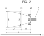
- FIG. 2 illustrates a shape of the electrophotographic roller according to the present disclosure.
- FIG. 2 illustrates an enlarged view from the center of the electrophotographic roller in the longitudinal direction to one end portion of the mandrel 1.
- An electrophotographic roller includes a mandrel and an elastic layer on the mandrel; and has a crown shape in which the diameter decreases from the central portion toward both ends in a longitudinal direction of the mandrel.
- a position of an end portion in a longitudinal direction of the elastic layer is defined as X2
- a position between a central position O and X2 is defined as X1
- a distance between the central position O and X1 is defined as L1
- a distance between the X1 and X2 is defined as L2
- L1 0.6 ⁇ (L1 + L2)
- a charging roller which is commonly used is brought into contact with a photosensitive member so that a predetermined pressure is applied to both end portions of a mandrel 1. Because of this, when the outer diameter of the elastic layer of the charging roller is constant from the central position in the longitudinal direction of the mandrel to the end portions of the elastic layer, the pressing force at the end portion becomes larger than the pressing force at the central portion. In order to reduce the unevenness of the pressure distribution in the longitudinal direction, the charging roller has such a crown shape that the diameter decreases from the center in the longitudinal direction of the mandrel toward both ends, as is illustrated in FIG. 2 .
- the crown amount in the present disclosure is defined as (Do-DX2)/2.
- Do and DX2 represent average values of diameters at respective arbitrary points.
- the crown amount is preferably 0.01 mm or larger and 0.26 mm or smaller.
- a suitable crown amount changes depending on a pressing load applied to both ends of the mandrel.
- the crown amount is preferably 0.15 mm or larger and 0.25 mm or smaller, and is more preferably 0.20 mm or larger and 0.25 mm or smaller, in order to enhance the uniformity of the pressure.
- a position between the central position O and the X2 is defined as X1
- a distance between the central position O and the X1 is defined as L1
- a distance between the X1 and the X2 is defined as L2
- the Z1 is a decrement of a "radius at position X1" relative to a "radius at central position O" of the mandrel.
- the Z2 is a decrement of a "radius at position X2" relative to a "radius at position X1".
- Each of the Z1 and the Z2 is determined to be an arithmetic mean value of values calculated at 180 positions at a pitch of 1 degree in a circumferential direction of the roller.
- the electrophotographic roller in the present disclosure has a shape in which Z1, Z2, L1 and L2 satisfy the following calculation expression (1): Z 2 / L 2 ⁇ ⁇ ⁇ Z 1 / L 1 wherein ⁇ is 1.931.
- the constant ⁇ represents a change rate of curvature in the central region and the end region of the roller.
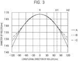
- FIG. 3 illustrates roller shapes in which the respective curvatures of the end regions are different.
- the shapes of rollers B and C according to one aspect of the present disclosure are indicated by a broken line and an alternate long and short dash line, respectively.
- the shape of a roller A having a general crown shape illustrated in FIG. 3 is illustrated by a solid line.
- Table 1 shows each of numerical values of Z1, L1, Z2 and L2 of the rollers A to C, and values of ⁇ , which are calculated from these numerical values with the use of the following calculation expression.
- ⁇ Z 2 / L 2 / Z 1 / L 1
- FIG. 3 illustrates diameters at positions in the longitudinal direction of the rollers, respectively.
- Y a X ⁇ b 2 + c (wherein a, b and c are arbitrary constants)
- the diameters in the end region (between the X1 and the X2) also gradually decrease, and the difference in the peripheral speed between the photosensitive member and the roller has been large in the end region.
- an electrophotographic roller having the general crown shape such as the roller A is used as the charging roller, a large difference in the peripheral speed occurs between the photosensitive member and the electrophotographic roller (charging roller) in the end region. Then, due to the difference in the peripheral speed, the toner and the external additive which interpose between the photosensitive member and the electrophotographic roller are rubbed against the outer surface of the electrophotographic roller and stick thereto.
- Such a sticking matter causes abnormal discharge from the electrophotographic roller to the photosensitive member, and as a result, a spot (hereinafter, also referred to as "white spot") is formed in some cases, which should not be originally formed in an electrophotographic image.
- a spot hereinafter, also referred to as "white spot"
- This phenomenon remarkably occurs, in particular, in such a low-temperature and low-humidity environment that the temperature is 15°C and the relative humidity is 10%, for example.
- the electrophotographic roller having the general crown shape like the roller A is used as the developing roller, a large difference in the peripheral speed occurs between the photosensitive member and the electrophotographic roller (developing roller), in the end region. Then, due to the difference in the peripheral speed, the toner which interposes between the photosensitive member and the electrophotographic roller is rubbed against the surface of the electrophotographic roller, and sticks thereto. Such a sticking matter reduces such a capability of the electrophotographic roller as to give an electric charge to the toner. As a result, the toner cannot be sufficiently charged on the developing roller.
- the toner having an insufficient amount of the electrostatic charge is transferred onto the surface of the photosensitive member, onto which the toner should not be transferred originally, and causes fogging in an electrophotographic image.
- This phenomenon occurs particularly remarkably in a high-temperature and high-humidity environment in which the temperature is 40°C and the relative humidity is 95%, for example.
- the curvature of the outer diameter of the end region is smaller than that of the central region.
- the radius of curvature is large.
- the nip width is more uniform in the longitudinal direction.
- the difference in the peripheral speed from the photosensitive member is smaller than that of the roller A. Because of this, even when the roller B or the roller C is used as the charging roller and is applied to an image forming process which has been speeded up, the occurrence of the blot in the end region is slight compared to that of the roller A.
- the electrophotographic roller can reduce or prevent the occurrence of the blot in the end region and suppress the occurrence of the fogging at a position corresponding to the end region of the electrophotographic image.
- the constant ⁇ needs to be controlled to be smaller than 1.931, for the purpose of uniformization of the contact pressure with respect to the photosensitive member, in addition to suppression for the blot which originates in the difference in the peripheral speed in the end region.
- it is necessary to control [(Z2/L2)/(Z1/L1)] to smaller than 1.931.
- it is preferably 1.000 ⁇ [(Z2/L2)/(Z1/L1)] ⁇ 1.931.
- a magnitude of a vibration at the time when the electrophotographic roller rotates while following the photosensitive member is proportional to a magnitude of the difference in the peripheral speed of the electrophotographic roller with respect to the photosensitive member.
- the magnitude (amplitude) of the vibration of the electrophotographic roller can be measured with a laser Doppler vibrometer (trade name: LV-1710, manufactured by Ono Sokki Co., Ltd.).
- the measurement position is set at a position close to the center by 5 mm from the end portion of the elastic portion of the electrophotographic roller, and is a position opposite to the contact position with the photosensitive member (opposite side by 180 degree).
- the electrophotographic roller is incorporated into the electrophotographic process cartridge, and the vibration is measured at the time when the electrophotographic apparatus is operated.
- the amplitude is evaluated by subjecting the vibration of the electrophotographic apparatus to frequency analysis, and evaluating the frequency with the largest amplitude.
- the amplitude and the difference in the peripheral speed are proportional to each other, and accordingly, a smaller amplitude means a smaller difference in the peripheral speed; but, from the viewpoint of preventing the blot originating in the difference in the peripheral speed, the amplitude is preferably 12 nm or less.
- the amount of fogging by toner after endurance at the time when electrophotographic roller is incorporated as a developing roller can be measured by a reflection densitometer (trade name: TC-6DS/A; manufactured by Tokyo Denshoku Co., Ltd.).
- An electrophotographic roller is incorporated into an electrophotographic process cartridge as a developing roller, and 1000 sheets of paper are continuously passed.
- a reflectance R1 at a position 5 mm distant from the end portion in the 1000th image is measured by the reflection densitometer.
- a reflectance R0 of unprinted paper is also measured with the reflection densitometer.
- the fogging value is 7% or smaller, it is determined that the influence of the lowering of the capability of giving the electric charge to the developing roller is small and the fogging does not occur.
- a non-contact type laser length measuring instrument can be used for the measurement of the outer diameter of the electrophotographic roller.
- the non-contact type laser length measuring instrument for example, there is a laser scan type of dimension/outer diameter measuring instrument "LS-5000" (trade name) manufactured by Keyence Corporation.
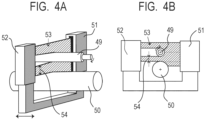
- FIG. 4A and FIG. 4B illustrate a method of measuring an outer diameter with the use of the above laser scan type of dimension/outer diameter measuring instrument.
- FIG. 4A illustrates a perspective view of a state in which an electrophotographic roller 49 which is a measurement object and a reference roller 50 are placed on the measuring instrument
- FIG. 4B illustrates a side view thereof.
- a light receiving portion 52 receives a laser beam 53 (hatched portion) emitted from a laser light emitting portion 51.
- the reference roller 50 is placed on the measuring instrument so that its axis and the laser beam 53 are orthogonal to each other.
- the electrophotographic roller 49 as the measurement object is placed on the measuring instrument so as to be parallel to the axial line of the reference roller 50.
- a width 54 of the laser beam is measured which has been emitted from the laser emitting portion 51 and has transmitted between the reference roller 50 and the electrophotographic roller 49.
- the measurement pitch is preferably 2 mm or smaller in the longitudinal direction, and 5 degrees or smaller in the rotational direction, and is more preferably 1 mm pitch in the longitudinal direction and 1 degree pitch in the rotational direction. As illustrated in FIG.
- the distance between the X1 and the X2 is denoted by L2.
- the diameter of the electrophotographic roller 49 is measured as a width of the laser which has been interrupted by the electroconductive base layer roller 49. Specifically, the diameter is measured every time the electrophotographic roller 49 is rotated, and the diameter of one circumference of the electrophotographic roller 49 is determined in one measurement cross section. The diameter in the present disclosure is defined as an average value of diameters of one circumference in each cross section. Next, the electrophotographic roller 49 is moved in the longitudinal direction, and a diameter is measured at another position in the longitudinal direction.
- FIG. 5 illustrates one example of a load-displacement curve required in a process of deriving the elastic deformation power.
- a load application curve 301 (curve from point A to point B) profiles a behavior of displacement with respect to a load, at the time when the load is applied to an object.
- a load-unloading curve 302 (curve from point B to point C) profiles a behavior of displacement with respect to the load, at the time when the load is unloaded from the object.
- a work amount at the time when the load is applied (area of region 303 surrounded by load application curve 301, load-unloading curve 302, and straight line from point A to point C) is denoted by Wp (plastic deformation work amount).
- a work amount at the time when the load is unloaded (area of region 304 surrounded by load-unloading curve 302, straight line from point B to point D, and straight line from point C to point D) is denoted by We (elastic deformation work amount).
- the total work amount is denoted by Wt (total deformation work amount).
- the electrophotographic roller has a high property of returning to an original state even if having been deformed, in other words, has a high elastic recovery rate.
- the roller surface having high ⁇ IT even though a stress is applied thereto because of a pressure or the difference in the peripheral speed, in a state in which a blot such as the toner or the external additive such as a toner shell or silica adheres to the roller surface, the toner or the external additive resists sticking, because the elastic recovery rate of the roller is high. Because of this, the roller surface having the high ⁇ IT is more advantageous for preventing the adhesion of the blot to the end region.
- FIG. 6A and FIG. 6B schematically illustrate a state at the time when an electrophotographic roller is incorporated as a charging roller into an electrophotographic apparatus, the endurance of 1,000 sheets has been evaluated, then the electrophotographic roller has been removed and cut, and the cross section has been observed.
- FIG. 6A illustrates a case where the ⁇ IT is 40%
- FIG. 6B illustrates a case where the ⁇ IT is 55%.
- Detailed endurance conditions will be described in Example 1.
- the ⁇ IT is set to 56% or larger, which is effective for suppressing the burying of the blot of the external additive into the charging roller, but is preferably 65% or larger for the purpose of more effectively suppressing the burying, and is more preferably 75% or larger from the same viewpoint.
- FIG. 1 schematically illustrates an external view of the electrophotographic roller.
- the electrophotographic roller has a structure having an elastic layer 2 on the outer circumference of a mandrel 1, in which both ends of the mandrel 1 are exposed without being covered with the elastic layer 2.
- the charging roller is provided in an electrophotographic image forming apparatus, as a charging unit that electrically charges the photosensitive member. Specifically, the charging roller is brought into contact with the photosensitive drum, is driven by the photosensitive member of the photosensitive drum, and is charged by friction at a contact portion between the photosensitive drum and the charging roller.
- the developing roller is provided as a unit for stably supplying the toner to the photosensitive member.
- the mandrel 1 that is used in the elastic roller of the present disclosure has electroconductivity, and has a function of supporting the elastic layer or the like, which is provided on the outer circumference thereof.
- the material include metals such as iron, copper, stainless steel, aluminum and nickel, and alloys thereof. In addition, these materials may be subjected to plating treatment or the like, in order that these surfaces are imparted with scratch resistance.
- a mandrel can also be used that is a substrate formed from a resin, of which the surface is coated with a metal or the like and imparted with surface electroconductivity, or a mandrel can also be used that is produced from an electroconductive resin composition.
- an adhesive layer (unillustrated) may be provided between the mandrel 1 and the elastic layer 2.
- the adhesive is electroconductive.
- appropriate agents are selected from known electroconductivity imparting agent (for example, ion conductivity imparting agent and electron conductivity imparting agent), and can be used alone or in combination of two or more thereof, for the adhesive.
- binder of the adhesive examples include thermosetting resins and thermoplastic resins, and known binders can be used such as urethane-based, acrylic-based, polyester-based, polyether-based and epoxy-based binders.
- known binders can be used such as urethane-based, acrylic-based, polyester-based, polyether-based and epoxy-based binders.
- the adhesive examples include METALOC N33 (epoxy-based adhesive having electroconductivity, produced by Toyokagaku Kenkyusho Co., Ltd.).
- a coating method of the adhesive known methods can be used such as a roll coater, sponge coating and spray coating.
- the adhesive layer between the mandrel 1 and the elastic layer 2 may be provided over the whole face at which the mandrel 1 and the elastic layer 2 come in contact with each other, or may be provided only in the range of from 5 mm to 20 mm by width at both end portions of the face at which the mandrel 1 and the elastic layer 2 come in contact with each other.
- the thickness of the adhesive layer is preferably 1 ⁇ m to 10 ⁇ m.
- the elastic layer 2 provided on the outer circumferential surface of the mandrel 1 may be a solid body or a foamed body, and may be a single layer or may be formed of a plurality of layers.
- a hardness of the elastic layer 2 is 10 degrees or higher and 70 degrees or lower by an Asker C hardness.
- the Asker C hardness of the elastic layer 2 is 10 degrees or higher, exudation of an oil component from a rubber material constituting the elastic layer 2 can be easily suppressed, and contamination of a contact member such as a photosensitive drum can be suppressed.
- the Asker C hardness of the elastic layer 2 is 70 degrees or lower, the contact of the elastic roller with the contact member becomes stable, and deterioration in an image quality of the output image can be suppressed.
- the Asker C hardness can be defined by a measurement value that is measured by an Asker Rubber hardness meter (manufactured by Kobunshi Keiki Co., Ltd.) with the use of a test piece which has been separately prepared according to the standard specification Asker C type SRIS (The society of Rubber Industry, Japan standard) 0101.
- the material for forming the elastic layer contains a binder resin and an electroconductive particle.
- binder resin examples include the following. Rubbers and thermoplastic elastomers including: natural rubber, butadiene rubber, styrene-butadiene rubber (SBR), nitrile rubber, ethylene propylene rubber (EPDM), chloroprene rubber (CR), acrylonitrile butadiene rubber (NBR), epichlorohydrin rubber, butyl rubber, silicone rubber, urethane rubber, fluorine rubber and chlorine rubber.
- SBR styrene-butadiene rubber
- EPDM ethylene propylene rubber
- NBR chloroprene rubber
- NBR acrylonitrile butadiene rubber
- epichlorohydrin rubber butyl rubber
- silicone rubber urethane rubber
- fluorine rubber and chlorine rubber urethane rubber
- electroconductive carbons can be used such as Ketjen Black EC, acetylene black, carbon for rubber, carbon for color (ink) subjected to oxidation treatment, and pyrolytic carbon.
- Specific examples of the carbon for rubber include the following carbons for rubber.
- Super Abrasion Furnace SAF: super abrasion resistance
- Intermediate Super Abrasion Furnace ISIF: intermediate super abrasion resistance
- High Abrasion Furnace HAF: high abrasion resistance
- FEF Fast Extruding Furnace
- GPF General Purpose Furnace
- SRF medium reinforcement
- Fine Thermal FT: fine particle thermal decomposition
- MT Medium Thermal decomposition
- graphite can also be used such as natural graphite and artificial graphite.
- Examples of the usable electroconductive particle include: particles of metallic oxides such as TiO 2 , SnO 2 and ZnO; particles of composite oxides such as solid solutions of ZnO and Al 2 O 3 ; powders of metals such as Cu and Ag; and various known particles.
- the particles may be used alone, or a blend of two or more types thereof may be used.
- a spherical particle which has a particle diameter, for example, in a range of 1 ⁇ m to 90 ⁇ m.
- the spherical particle include at least one spherical particle selected from the following particles: a phenol resin particle, a silicone resin particle, a polyacrylonitrile resin particle, a polystyrene resin particle, a polyurethane resin particle, a nylon resin particle, a polyethylene resin particle, a polypropylene resin particle, an acrylic resin particle, a silica particle, and an alumina particle. Due to the use of such a rubber composition, a charging roller can be produced in which the outer surface of the elastic layer has projecting portions derived from the spherical particle.
- a vulcanizing agent if necessary, a vulcanizing agent, a vulcanization accelerator, an electroconductivity imparting agent, a charge control agent, a plasticizer, an anti-aging agent and the like can be appropriately added.
- an antistatic agent, an ultraviolet absorber, a reinforcing agent, a filler, a lubricant, a mold release agent, a pigment, a dye, a flame retardant and the like can be appropriately added, as needed.
- the electrophotographic roller As a method for manufacturing the electrophotographic roller according to one aspect of the present disclosure, there is a method of coating the mandrel with the material for forming the elastic layer, with the use of an extrusion machine having a crosshead, for example.
- FIG. 7 is an explanatory view of a process of forming a layer of the material for forming the elastic layer on the outer circumferential surface of the mandrel, by coextruding the mandrel and the material for forming the elastic layer with the use of an extrusion molding machine 7 provided with a crosshead 74.
- the extrusion molding machine 7 is provided with the crosshead 74 into which the mandrel 71 and the material 72 for forming the elastic layer are fed, a feed roller 75 which feeds the mandrel 71 into the crosshead 74, and a cylinder 76 which feeds the material 72 for forming the elastic layer into the crosshead 74.
- the material 72 for forming the elastic layer is fed into the crosshead 74 by a screw 77 in a cylinder 76, and at the same time, the mandrel 71 is fed into the crosshead 74; and thereby, the mandrel 71 having the layer of the material for forming the elastic layer is discharged from the crosshead, which is formed on the outer circumferential surface.
- the mandrel which has the layer of the material for forming the elastic layer formed on the outer circumferential surface is also referred to as a "coated roller 73".
- the outer diameter of the electrophotographic roller according to one aspect of the present disclosure can be controlled by changing a relative ratio between the feed speed of the mandrel 71 to the crosshead by the feed roller 75 and the feed speed of the material for forming the elastic layer from the cylinder 76.
- the thickness of the elastic layer in the longitudinal direction of the mandrel can be adjusted by keeping the feed speed of the material for forming the elastic layer from the cylinder to the crosshead constant, and changing the feed speed of the mandrel 71 to the crosshead.
- the thickness of the elastic layer can be relatively thinned, in other words, the diameter can be reduced.
- (First step) A step of obtaining a relationship between the feed speed of the mandrel to the crosshead and the thickness of the layer of the material for forming the elastic layer, which is formed on the mandrel, by performing preforming of keeping the feed speed of the material for forming the elastic layer to the crosshead constant, and changing the feed speed of the mandrel to the crosshead;
- the rotation speed of the feed roller 75 is increased to increase the feed speed of the mandrel, and thereby the outer diameter becomes small.
- the rotation speed of the feed roller 75 is decreased to decrease the feed speed of the mandrel, and thereby the outer diameter becomes large.
- the crown-shaped electrophotographic roller according to the present disclosure is obtained by the above method, it is preferable to determine the target shape at the time of extrusion molding, considering that there is a case where the elastic layer shrinks in the subsequent vulcanizing step.
- the electrophotographic roller can also be manufactured by operations of: producing a coated roller having an outer diameter equal to the outer diameter of the thickest central portion of the target crown shape or larger than the outer diameter of the thickest central portion, while keeping the feed speed of the mandrel to the crosshead and the feed speed of the material for forming the elastic layer constant; and grinding the outer circumferential surface of the rubber layer obtained by curing the layer of the material for forming the elastic layer, with the use of a grindstone or the like.
- the molded electrophotographic roller precursor is heated and vulcanized by units of a hot air oven, a vulcanizing can, a hot plate, far-near infrared rays, induction heating and the like.
- the heating temperature varies depending on the material for forming the elastic layer, but is preferably 130 to 250°C, and is more preferably 140 to 220°C; and the heating time is preferably 5 to 240 minutes, and is more preferably 10 to 60 minutes.
- a vulcanized rubber composition at both end portions of the vulcanized rubber roller is removed in a later separate step, and the electrophotographic roller is completed. Accordingly, both end portions of the core metal are exposed in the completed electrophotographic roller.
- the surface layer may be subjected to surface treatment such as ultraviolet irradiation for the purpose of reducing a friction coefficient of the surface, or electron beam irradiation for the purpose of enhancing the ⁇ IT.
- surface treatment such as ultraviolet irradiation for the purpose of reducing a friction coefficient of the surface, or electron beam irradiation for the purpose of enhancing the ⁇ IT.
- FIG. 8 illustrates one example of a process cartridge for electrophotography, which is provided with a charging roller according to one embodiment of the present disclosure.
- the process cartridge 100 illustrated in FIG. 8 is configured so that a developing apparatus and a charging apparatus are integrated, and so as to be detachably attachable to a main body of an electrophotographic apparatus.
- the developing apparatus is formed by integrating at least a developing roller 103, a toner container 106, and a toner 109.
- the photosensitive drum 101 is one example of an electrophotographic photosensitive member.
- the developing apparatus may include a toner supply roller 104, a developing blade 108, and a stirring vane 110, as needed.
- the charging apparatus is formed by integrating at least the photosensitive drum 101 and a charging roller 102.
- the charging roller 102 is arranged at a position at which the photosensitive drum101 can be electrically charged.
- the charging apparatus may be provided with a cleaning blade 105 and a waste toner container 107.
- the charging roller 102, the developing roller 103, the toner supply roller 104 and the developing blade 108 are configured so that voltages are applied thereto, respectively.
- FIG. 9 illustrates a view illustrating one example of the electrophotographic apparatus that uses the charging roller according to one embodiment of the present disclosure.
- the electrophotographic apparatus 200 illustrated in FIG. 9 is configured so that four process cartridges 100 are detachably attached thereto.
- Each process cartridge 100 corresponds to each color of black, magenta, yellow and cyan, and toners corresponding to the respective colors are used.
- Each process cartridge 100 has the same configuration except that the color of the toner to be used is different.
- Each process cartridge 100 has basically the same configuration as that illustrated in FIG. 8 .
- the process cartridge 100 includes a photosensitive drum 201, a charging roller 202, a developing roller 203, a toner supply roller 204, a cleaning blade 205, a toner container 206, a waste toner storage container 207, a developing blade 208, a toner 209, and a stirring vane 210.
- the photosensitive drum 201 rotates in an arrow direction (clockwise direction), and is uniformly charged by the charging roller 202 to which a voltage is applied from a charging bias power source.
- a voltage is applied from a charging bias power source.
- the toner 209 stored in the toner container 206 is supplied to the toner supply roller 204 by the stirring vane 210.
- the toner supply roller 204 supplies the toner 209 to the developing roller 203.
- the surface of the developing roller 203 is uniformly coated with the toner 209 by the developing blade 208 which is arranged in contact with the developing roller 203, and an electric charge is given to the toner 209 by frictional charging.
- the above electrostatic latent image is developed by being imparted with the toner 209 that is conveyed by the developing roller 203 which is arranged in contact with the photosensitive drum 201, and is visualized as a toner image.
- the visualized toner image on the photosensitive drum is transferred onto an intermediate transfer belt 215 by a primary transfer roller 212 to which a voltage is applied by a primary transfer bias power source.
- the intermediate transfer belt 215 is supported and driven by a tension roller 213 and an intermediate transfer belt drive roller 214.
- the toner images of the respective colors are sequentially superimposed to form a color image on the intermediate transfer belt 215.
- a transfer material 219 is fed into the apparatus by a sheet feeding roller.
- the transfer material 219 is conveyed to between the intermediate transfer belt 215 and a secondary transfer roller 216.
- a voltage is applied to the secondary transfer roller 216 from a secondary transfer bias power source, and the color image on the intermediate transfer belt 215 is transferred to the transfer material 219.
- the transfer material 219 to which the color image has been transferred is subjected to a fixing process by a fixing device 218.
- the transfer material 219 that has been subjected to the fixing process is discharged to the outside of the apparatus.
- the toner which has remained on the photosensitive drum 201 without being transferred is scraped off by the cleaning blade 205, and is stored in a waste toner storage container 207.
- the toner which has remained on the intermediate transfer belt 215 without being transferred is also scraped off by a cleaning apparatus 217.
- an electrophotographic roller can be obtained that can suppress the adhesion of the blots in the end region of the electrophotographic roller, even in a high-speed electrophotographic apparatus.
- a process cartridge can be obtained that contributes to stable formation of a high-quality electrophotographic image.
- an electrophotographic image forming apparatus can be obtained that can stably form a high-quality electrophotographic image.
- an unvulcanized rubber composition 1 was obtained by mixing materials shown in the following Table 3.
- an open roll product name: 12 ⁇ 30 test roll, manufactured by Kansai Roll Co., Ltd.
- the number of rotations of the front roll was set at 10 rpm
- the number of rotations of the rear roll was set at 8 rpm
- the roll gap was set at 2 mm; left and right were turned back 20 times in total; and then the roll gap was set at 0.5 mm, and tight milling was performed 10 times.
- Sulfur 1 Vulcanization accelerator 3 (Trade name: Nocceller TBzTD; produced by Ouchi Shinko Chemical Industrial Co., Ltd.)
- An extrusion molding temperature was set at 100°C for each of the cylinder, a screw and a crosshead die.
- the number of rotations of the screw was set at 10 rotations per minute. These conditions were adopted, and the mandrel was coated with the unvulcanized rubber composition 1.
- the feed speed of the feed roll was controlled and the wall thickness was adjusted so that the shape of the charging roller became a crown shape after the electrophotographic roller precursor was vulcanized and the end portion of the elastic layer was removed, and in addition, the shape of the electrophotographic roller after the end portion of the elastic layer was removed showed that the values of L1, L2, Z1 and Z2 illustrated in FIG. 2 were the respective values shown in Table 4; and the electrophotographic roller precursor was formed.
- an inflow speed of the material for forming the elastic layer into the crosshead was kept constant at 5.20 ⁇ 10 -4 mm 3 /second; and on the other hand, when the layer of the material for forming the elastic layer was formed, and the central portion in the longitudinal direction of the mandrel was formed, the feed speed of the mandrel to the crosshead was set at 4.70 mm/second, and when both of the end portions were formed, the feed speed of the mandrel to the crosshead was set at 5.80 mm/sec.
- the thickness (diameter) of the layer of the material for forming the elastic layer around the mandrel immediately after having been extruded from the crosshead was measured with the use of a laser measuring device, and feedback control of the feed speed of the mandrel was performed, based on the relationship between the feed speed and the diameter of the mandrel acquired in advance in the preforming.
- the obtained electrophotographic roller precursor was heated in a hot air oven at 160°C for 1 hour, and then both of the end portions of the layer of the material for forming the elastic layer in the electrophotographic roller precursor were removed by 10 mm; and an electrophotographic roller 1 was obtained.
- the length of the elastic layers in the longitudinal direction of the electrophotographic roller 1 was 230 mm; and L1 was 69 mm and L2 was 46 mm.
- the surface of the obtained electrophotographic roller was irradiated with ultraviolet rays, and an electrophotographic roller 1' was obtained which had UV-treated region on the surface of the elastic layer.
- a low-pressure mercury-vapor lamp (trade name: GLQ500US/11, manufactured by Toshiba Lighting & Technology Corporation Co., Ltd.) was used for the irradiation of ultraviolet rays, and the electrophotographic roller was uniformly irradiated while having been rotated at a constant speed while the mandrel 1 was regarded as a rotational axis.
- the amount of the ultraviolet rays was set so as to be 9000 mJ/cm 2 in terms of the sensitivity of the sensor for 254 nm.
- the outer diameter of the electrophotographic roller 1' was measured with the use of a non-contact laser measuring instrument, according to a configuration illustrated in FIG. 4A and FIG. 4B .
- the shape of the roller was measured with the use of a non-contact laser measuring instrument (LS-5000; manufactured by Keyence Corporation), by the operation of moving the roller at a 1mm pitch in the longitudinal direction and at a pitch of 1 degree in the rotational direction.
- the diameter in the present disclosure is defined as an average value of diameters of one circumference in each cross section.
- Do was 7. 69 mm
- Z1 and Z2 became as shown in Table 4.
- an approach speed of an indenter was 100 nm/s; as for a load condition, the maximum load was 1 mN, and an indentation time was 3s; and an unloading condition was the reverse of the load condition.
- the measurement points were 36 points in total of 12 points at intervals of 30 degrees in the circumferential direction, for three points in total of the central position in the longitudinal direction of the electrophotographic roller and two positions close to the center by 10.0 mm from both end portions of the elastic layer, and measurement was performed there.
- the test was performed under the above conditions to obtain a load-displacement curve of the electrophotographic roller 1', and the ⁇ IT was calculated for each curve.
- the median value of ⁇ ITs at 36 points is denoted by the ⁇ IT.
- the electrophotographic roller 1' is incorporated into the process cartridge as a charging roller, the vibration of the charging roller is measured at the time when an electrophotographic apparatus is operated, and a magnitude of the amplitude is evaluated as a magnitude of the difference in the peripheral speed.
- a laser Doppler vibrometer (trade name: LV-1710, manufactured by Ono Sokki Co., Ltd.) was used. The measurement position was set at a position close to the center by 5 mm from the end portion of the elastic portion of the electrophotographic roller, on a position opposite to the contact position with the photosensitive member (position on the opposite side by 180 degree).
- Lasejet M608dn manufactured by HP Inc.
- An electrophotographic process cartridge for the above printer was used as the electrophotographic process cartridge. Vibrations were measured at the time when the printer was operated, and the frequencies were analyzed; as a result, the amplitude was large at a frequency of 2700Hz; and the magnitude of the amplitude at the frequency of 2700Hz was adopted as the magnitude of the vibration of the charging roller 1.
- Table 6 The measurement results are shown in Table 6.
- the electrophotographic roller 1' was incorporated into an electrophotographic apparatus as a charging roller, and was subjected to a paper passing endurance test under a low-temperature and low-humidity environment.
- a laser printer (trade name: Laserjet M608dn; manufactured by HP Inc.) was prepared. The laser printer was used after having been modified so that the number of output sheets per unit time became 75 sheets/min (A4 vertical output), which was larger than the original number of output sheets, in order to perform evaluation in a high-speed process.
- the resolution of an image of the above laser printer is 600 dpi, and the output of primary charging is a DC voltage of -1100V.
- An electrophotographic process cartridge for the above printer was used as the electrophotographic process cartridge.
- the electrophotographic process cartridge includes a drum-shaped electrophotographic photosensitive member and a charging roller which is arranged in contact with the electrophotographic photosensitive member.
- a pressure of 250 g is applied to each of both ends of the mandrel body of the charging roller, and thereby the charging roller is pressed against the electrophotographic photosensitive member.
- the electrophotographic roller 1', the electrophotographic apparatus and the process cartridge were left to stand in an environment at a temperature of 15°C and a relative atmospheric humidity of 10% for 48 hours, for the purpose of being acclimated to the measurement environment.
- the electrophotographic roller 1' was incorporated into the process cartridge as a charging roller.
- the output image was evaluated with the use of the process cartridge.
- an E character image having a print density of 1% was subjected to the endurance (image output) of continuous 1000 sheets, under a low-temperature and low-humidity environment (temperature of 15°C, and relative humidity of 10%).
- a halftone image image in which horizontal lines each having width of 1 dot in direction perpendicular to rotation direction of electrophotographic photosensitive member and interval of 2 dots were drawn was output.
- the obtained image was visually observed, and an image defect was observed which originates in the adhesion of the blot on the surface of the charging roller.
- the degree of the adhesion of the blots of the toner and external additives on the surface of the electrophotographic roller 1' was observed, with a digital microscope (model number VH-8000, manufactured by Keyence Corporation).
- a digital microscope model number VH-8000, manufactured by Keyence Corporation.
- the observation positions two positions were observed which were sides by 10 mm inner from the end portions of the elastic layer, respectively, and a position at which the adhesion state of the blot was inferior was determined to be places to be evaluated.
- An electrophotographic roller 1' was obtained in the same manner as in Example 1, except that the numerical values of Z1, Z2 and (Do-DX2)/2 were controlled as shown in Table 4.
- the obtained electrophotographic roller 1' was evaluated in the same manner as in Example 1. The results are shown in Table 6.
- Electrophotographic rollers 1' were obtained in the same manner as in Example 1, except that the numerical values of Z1, Z2 and (Do-DX2)/2 were controlled as shown in Table 4.
- Laserjet M608dn manufactured by HP Inc. was prepared as an electrophotographic apparatus, was modified so that the number of output sheets per unit time became 100 sheets/min (A4 vertical output), which was larger than the original number of output sheets, in order to perform the evaluation in a high-speed process, and was used.
- the surface of the obtained electrophotographic roller was irradiated with an electronic beam, and an electrophotographic roller was obtained which had EB-treated region on the surface of the elastic layer.
- an electron-beam irradiation apparatus having a maximum acceleration voltage of 70 kV (trade name: "low-energy electron-beam irradiation source EB-ENGINE" manufactured by Hamamatsu Photonics K.K.) was used.
- the air in the irradiation chamber was purged with nitrogen gas, and the oxygen concentration in the irradiation chamber was adjusted.
- the treatment conditions were as follows: acceleration voltage: 70 kV, electronic current (irradiation current): 1.5 mA, treatment speed (scanning speed): 0.6 m/min, and concentration of oxygen: 800 ppm.
- acceleration voltage 70 kV
- electronic current irradiation current
- treatment speed 0.6 m/min
- concentration of oxygen 800 ppm.
- the apparatus constant at the acceleration voltage of 70 kV in the electron-beam irradiation apparatus was 218, and the dose calculated by Expression (1) was 1635 kGy.
- D K ⁇ I / V
- An electrophotographic roller 1" shown in Table 4 was obtained in the same manner as in Example 1, except for the above.
- the obtained electrophotographic roller 1" was evaluated in the same manner as in Example 1. The evaluation results are shown in Table 6.
- An electrophotographic roller 1" having an EB-treated region on the surface of the elastic layer was obtained in the same manner as in Example 1, except that among the conditions of the electron-beam irradiation in Example 7, an electronic current was set at 3.0 mA and the electron-beam irradiation was performed.
- Z1, Z2 and the like are shown in Table 4.
- the obtained electrophotographic roller 1" was evaluated in the same manner as in Example 1. The evaluation results are shown in Table 6.
- An electrophotographic roller 1" having an EB-treated region on the surface of the elastic layer was obtained in the same manner as in Example 1, except that among the conditions of the electron-beam irradiation in Example 7, an electronic current was set at 4.5 mA and the electron-beam irradiation was performed.
- Z1, Z2 and the like are shown in Table 4.
- the obtained electrophotographic roller 1" was evaluated in the same manner as in Example 1. The evaluation results are shown in Table 6.
- An electrophotographic roller was obtained in the same manner as in Example 1, except that the surface of the electrophotographic roller was not treated. Z1, Z2 and the like are shown in Table 4. The evaluation results are shown in Table 6.
- Example 2 With the use of the crosshead extrusion molding machine used in Example 1, a coated roller was formed so that an outer diameter of 8.00 mm at the time when having been extruded from the molding machine became a straight shape. After that, the coated roller was heated in a hot air oven at 160°C for 60 minutes, and an electrophotographic roller precursor was produced. Subsequently, both end portions of the vulcanized rubber layer were each removed by 10 mm, the surface of the vulcanized rubber layer of the electrophotographic roller precursor was ground by a plunge cut grinding type of grinding machine, and an electrophotographic roller 1′′′ was obtained of which the numerical values of Z1, Z2, (Do-DX2)/2 were as shown in Table 4. Except for that, the same procedure as those in Example 1 was employed. The evaluation results are shown in Table 6.
- the electrophotographic roller 1' produced in Example 1 was incorporated into an electrophotographic apparatus as a developing roller, and was subjected to a paper passing endurance test. Fogging was evaluated with the use of Laserjet Pro M102w Printer (manufactured by HP Inc.) as the electrophotographic apparatus. Firstly, the electrophotographic apparatus loaded with the electrophotographic roller 1' was placed in an environment of a temperature of 40°C and a relative atmospheric humidity of 95%, and then was left to stand for 12 hours or longer.
- a reflection densitometer (trade name: TC-6DS/A; manufactured by Tokyo Denshoku Co., Ltd.) was used.
- Fogging value R 0 % ⁇ R 1 %
- Example 1 The rubber among the materials of the unvulcanized rubber composition in Example 1 was changed from NBR (grade N230SV, produced by JSR Corporation) to NBR (grade N230SL, produced by JSR Corporation). Except for that, the same procedure as those of Example 1 was employed. Z1, Z2 and the like are shown in Table 4. The evaluation results are shown in Table 6.
- Example 1 The rubber among the materials of the unvulcanized rubber composition in Example 1 was changed from NBR (grade N230SV, produced by JSR Corporation) to NBR (grade N230S, produced by JSR Corporation). Except for that, the same procedure as those in Example 1 was employed. Z1, Z2 and the like are shown in Table 4. The evaluation results are shown in Table 6.
- Electrophotographic rollers 1' were obtained in the same manner as in Example 1, except that the values of Z1, Z2 and (Do-DX2)/2 were controlled as shown in Table 4. The obtained electrophotographic rollers 1' were evaluated in the same manner as in Example 1. The evaluation results are shown in Table 6.
- Electrophotographic rollers 1' were obtained in the same manner as in Example 1, except that the values of Z1, Z2 and (Do-DX2)/2 were controlled as shown in Table 4. The obtained electrophotographic roller 1' was evaluated in the same manner as in Examples 3 to 6. The evaluation results are shown in Table 6.
Landscapes
- Physics & Mathematics (AREA)
- General Physics & Mathematics (AREA)
- Engineering & Computer Science (AREA)
- Plasma & Fusion (AREA)
- Computer Vision & Pattern Recognition (AREA)
- Electrostatic Charge, Transfer And Separation In Electrography (AREA)
- Rolls And Other Rotary Bodies (AREA)
Claims (13)
- Elektrophotographische Walze (49, 102), die einen Dorn (1) und eine elastische Schicht (2) auf dem Dorn (1) aufweist; und eine Kronenform hat, in der ein Durchmesser von einer zentralen Position O in einer Längsrichtung (X) des Dorns (1) in Richtung beider Enden davon abnimmt,
dadurch gekennzeichnet, dass
wenneine Position eines Endabschnitts in der Längsrichtung (X) der elastischen Schicht (2) als eine Endposition X2 definiert ist,eine Position zwischen der zentralen Position O und der Endposition X2 als eine Position X1 definiert ist,ein Abstand zwischen der zentralen Position O und der Position X1 als L1 definiert ist ,undein Abstand zwischen der Position X1 und der Endposition X2 als L2 definiert ist,
wennAußendurchmesser der elektrophotographischen Walze (49, 102) an der zentralen Position O, der Position X1 und der Endposition X2 als Do, DX1 bzw. DX2 definiert sind und Z1 und Z2 wie folgt definiert sind:

 wobei die elektrophotographische Walze (49, 102) 1,000 < [(Z2/L2)/(Z1/L1)] < 1,931 erfüllt.
 - Elektrophotographische Walze (49, 102) nach Anspruch 1, wobei die elastische Schicht (2) eine Kronenform hat, in der ein Durchmesser der elastischen Schicht (2) von der zentralen Position O zu der Endposition X2 abnimmt.
- Elektrophotographische Walze (49, 102) nach Anspruch 1 oder 2, wobei, wenn ein Bereich von der zentralen Position O zu der Position X1 als eine zentrale Region definiert ist und ein Bereich von der Position X1 zu der Endposition X2 als eine Endregion definiert ist,
eine Krümmung der elastischen Schicht (2) in der Endregion kleiner ist als eine Krümmung der elastischen Schicht (2) in der zentralen Region. - Elektrophotographische Walze (49, 102) nach einem der Ansprüche 1 bis 3, wobei (Do-DX2)/2 0,01 mm oder größer und 0,26 mm oder kleiner ist.
- Elektrophotographische Walze (49, 102) nach einem der Ansprüche 1 bis 4, wobei eine elastische Verformungskraft der elastischen Schicht 56% oder höher ist, wobei die elastische Verformungskraft wie in der Beschreibung angegeben berechnet und gemessen wird.
- Elektrophotographische Walze (49, 102) nach einem der Ansprüche 1 bis 5, wobei die elastische Schicht Acrylnitril-Butadien-Gummi umfasst.
- Elektrophotographische Walze (49, 102) nach einem der Ansprüche 1 bis 6, wobei die elastische Schicht eine Asker C Härte von 10 Grad oder höher und 70 Grad oder niedriger hat.
- Elektrophotographische Walze (49, 102) nach einem der Ansprüche 1 bis 7, wobei eine Länge der elastischen Schicht (2) in der Längsrichtung (X) 220 mm oder länger und 340 mm oder kürzer ist.
- Prozesskartusche (100), die abnehmbar an einem Hauptkörper eines elektrophotographischen Bilderzeugungsgeräts (200) anbringbar ist und Folgendes aufweist:ein elektrophotographisches lichtempfindliches Bauteil (101); und eine elektrophotographische Walze (49, 102), die in Kontakt mit dem elektrophotographischen lichtempfindlichen Bauteil (101) ist, wobeidie elektrophotographische Walze (49, 102) die elektrophotographische Walze (49, 102) nach einem der Ansprüche 1 bis 8 ist.
- Prozesskartusche (100) nach Anspruch 9, wobei die elektrophotographische Walze (49, 102) eine Aufladungswalze (49, 102) ist, die das elektrophotographische lichtempfindliche Bauteil (101) elektrisch auflädt.
- Elektrophotographisches Bilderzeugungsgerät (200), das Folgendes aufweist:ein elektrophotographisches lichtempfindliches Bauteil (101); und eine elektrophotographische Walze (49, 102), die in Kontakt mit dem elektrophotographischen lichtempfindlichen Bauteil (101) ist, wobeidie elektrophotographische Walze (49, 102) die elektrophotographische Walze (49, 102) nach einem der Ansprüche 1 bis 8 ist.
- Elektrophotographisches Bilderzeugungsgerät (200) nach Anspruch 11, wobei die elektrophotographische Walze (49, 102) eine Aufladungswalze (49, 102) ist, die das elektrophotographische lichtempfindliche Bauteil (101) elektrisch auflädt.
- Elektrophotographisches Bilderzeugungsgerät (200) nach Anspruch 12, wobei das elektrophotographische lichtempfindliche Bauteil (101) angetrieben wird und die Aufladungswalze (49, 102) sich entsprechend der Drehung des elektrophotographischen lichtempfindlichen Bauteils (101) dreht.
Applications Claiming Priority (2)
| Application Number | Priority Date | Filing Date | Title |
|---|---|---|---|
| JP2021093293 | 2021-06-02 | ||
| JP2022076789A JP2022185567A (ja) | 2021-06-02 | 2022-05-06 | 電子写真用ローラ、プロセスカートリッジ、電子写真画像形成装置 |
Publications (2)
| Publication Number | Publication Date |
|---|---|
| EP4099095A1 EP4099095A1 (de) | 2022-12-07 |
| EP4099095B1 true EP4099095B1 (de) | 2025-04-30 |
Family
ID=81877996
Family Applications (1)
| Application Number | Title | Priority Date | Filing Date |
|---|---|---|---|
| EP22176619.9A Active EP4099095B1 (de) | 2021-06-02 | 2022-06-01 | Elektrofotographische walze, prozesskartusche und vorrichtung zur elektrofotografisches bilderzeugungsgerät |
Country Status (3)
| Country | Link |
|---|---|
| US (2) | US11644761B2 (de) |
| EP (1) | EP4099095B1 (de) |
| CN (1) | CN115437227B (de) |
Families Citing this family (4)
| Publication number | Priority date | Publication date | Assignee | Title |
|---|---|---|---|---|
| WO2022097743A1 (ja) | 2020-11-09 | 2022-05-12 | キヤノン株式会社 | 導電性部材、プロセスカートリッジ、及び電子写真画像形成装置 |
| US11644761B2 (en) * | 2021-06-02 | 2023-05-09 | Canon Kabushiki Kaisha | Electrophotographic roller, process cartridge and electrophotographic image forming apparatus |
| JP2025056886A (ja) | 2023-09-27 | 2025-04-09 | キヤノン株式会社 | 電子写真部材、プロセスカートリッジ、及び電子写真画像形成装置 |
| US12498646B2 (en) | 2023-09-27 | 2025-12-16 | Canon Kabushiki Kaisha | Electrophotographic conductive member, process cartridge, and electrophotographic image forming apparatus |
Family Cites Families (42)
| Publication number | Priority date | Publication date | Assignee | Title |
|---|---|---|---|---|
| US4420548A (en) | 1980-11-28 | 1983-12-13 | Canon Kabushiki Kaisha | Electrophotographic member with hydrazone or ketazine compounds |
| EP0458273B1 (de) * | 1990-05-21 | 1997-08-13 | Canon Kabushiki Kaisha | Aufladevorrichtung, Bilderzeugungsgerät mit einer solchen Vorrichtung und von dem Bilderzeugungsgerät abnehmbare Arbeitseinheit |
| US5378525A (en) * | 1992-07-23 | 1995-01-03 | Tokai Rubber Industries, Ltd. | Crowned resilient roll with coating layer and method of producing the same |
| JP3392021B2 (ja) | 1997-11-05 | 2003-03-31 | キヤノン株式会社 | プロセスカートリッジ及び画像形成装置 |
| JP2000206762A (ja) | 1999-01-11 | 2000-07-28 | Canon Inc | 帯電ロ―ラ、プロセスカ―トリッジ、及び画像形成装置 |
| JP2001117466A (ja) * | 1999-10-14 | 2001-04-27 | Canon Inc | プロセスカートリッジおよび画像形成装置 |
| JP2001350351A (ja) | 2000-06-05 | 2001-12-21 | Bridgestone Corp | 画像形成装置用ローラの製造方法 |
| JP4455454B2 (ja) | 2004-09-02 | 2010-04-21 | キヤノン株式会社 | 帯電部材、プロセスカートリッジおよび電子写真装置 |
| US7693457B2 (en) | 2004-12-28 | 2010-04-06 | Canon Kabushiki Kaisha | Charging member, process cartridge, and electrophotographic apparatus |
| JP5191085B2 (ja) | 2005-05-19 | 2013-04-24 | キヤノン化成株式会社 | 帯電ローラー |
| JP2007199264A (ja) * | 2006-01-25 | 2007-08-09 | Fuji Xerox Co Ltd | 画像形成装置 |
| JP2007206148A (ja) | 2006-01-31 | 2007-08-16 | Canon Chemicals Inc | 電子写真用帯電ローラ |
| EP1991915B1 (de) | 2006-02-28 | 2016-04-13 | Canon Kabushiki Kaisha | Ladegerät, prozesskartusche und elektrofotografische vorrichtung |
| JP2009116009A (ja) | 2007-11-06 | 2009-05-28 | Tokai Rubber Ind Ltd | 導電性ロール |
| JP2009222842A (ja) * | 2008-03-14 | 2009-10-01 | Kyocera Mita Corp | 画像形成装置 |
| CN102132222A (zh) * | 2008-08-22 | 2011-07-20 | 株式会社普利司通 | 带电辊 |
| JP2011022286A (ja) * | 2009-07-14 | 2011-02-03 | Bridgestone Corp | 導電性ローラ |
| JP2011043684A (ja) | 2009-08-21 | 2011-03-03 | Shin Etsu Polymer Co Ltd | 弾性ローラ、現像装置及び画像形成装置 |
| JP5875264B2 (ja) | 2010-07-13 | 2016-03-02 | キヤノン株式会社 | 帯電部材の製造方法 |
| EP2607960B1 (de) | 2010-08-20 | 2018-01-03 | Canon Kabushiki Kaisha | Ladeelement |
| JP2013040627A (ja) | 2011-08-11 | 2013-02-28 | Canon Inc | 弾性ローラの製造装置およびそれを用いた弾性ローラの製造方法 |
| CN104011600B (zh) * | 2011-12-14 | 2016-02-24 | 佳能株式会社 | 电子照相用构件、处理盒和电子照相设备 |
| KR101652614B1 (ko) | 2012-02-24 | 2016-08-30 | 캐논 가부시끼가이샤 | 대전 부재, 전자 사진 장치 및 프로세스 카트리지 |
| JP5926088B2 (ja) | 2012-03-29 | 2016-05-25 | 住友理工株式会社 | 電子写真機器用導電性ロール |
| JP5936595B2 (ja) | 2012-12-12 | 2016-06-22 | キヤノン株式会社 | 帯電部材、プロセスカートリッジ及び電子写真装置 |
| JP5755262B2 (ja) | 2013-01-24 | 2015-07-29 | キヤノン株式会社 | プロセスカートリッジおよび電子写真装置 |
| WO2014119245A1 (ja) | 2013-01-29 | 2014-08-07 | キヤノン株式会社 | 帯電部材、プロセスカートリッジ及び電子写真装置 |
| US9098006B2 (en) | 2013-04-03 | 2015-08-04 | Canon Kabushiki Kaisha | Roller member for electrophotography, process cartridge and electrophotographic apparatus |
| JP6016838B2 (ja) | 2013-04-03 | 2016-10-26 | キヤノン株式会社 | 電子写真用のローラ部材、プロセスカートリッジ及び電子写真装置 |
| JP2015028603A (ja) * | 2013-07-01 | 2015-02-12 | キヤノン株式会社 | 帯電装置及び画像形成装置 |
| US9274442B2 (en) | 2014-03-27 | 2016-03-01 | Canon Kabushiki Kaisha | Electrophotographic image forming apparatus having charge transport layer with matrix-domain structure and charging member having concavity and protrusion |
| JP6706101B2 (ja) * | 2015-03-27 | 2020-06-03 | キヤノン株式会社 | 電子写真用の導電性部材、プロセスカートリッジおよび電子写真装置 |
| EP3281064B1 (de) | 2015-04-03 | 2019-09-25 | C/o Canon Kabushiki Kaisha | Ladeelement, prozesskartusche und elektrofotografische vorrichtung |
| US9599914B2 (en) | 2015-04-03 | 2017-03-21 | Canon Kabushiki Kaisha | Electrophotographic member having bow-shaped resin particles defining concavity and protrusion at surface thereof |
| US9910379B2 (en) | 2015-10-26 | 2018-03-06 | Canon Kabushiki Kaisha | Charging member with concave portions containing insulating particles and electrophotographic apparatus |
| US9904199B2 (en) | 2015-10-26 | 2018-02-27 | Canon Kabushiki Kaisha | Charging member having outer surface with concave portions bearing exposed elastic particles, and electrophotographic apparatus |
| JP7034815B2 (ja) | 2017-04-27 | 2022-03-14 | キヤノン株式会社 | 帯電部材、電子写真プロセスカートリッジ及び電子写真画像形成装置 |
| US10248042B2 (en) | 2017-06-02 | 2019-04-02 | Canon Kabushiki Kaisha | Electrophotographic roller, process cartridge and electrophotographic apparatus |
| JP2019082673A (ja) * | 2017-10-30 | 2019-05-30 | エイチピー プリンティング コリア カンパニー リミテッド | 帯電ローラ |
| US10481516B2 (en) * | 2018-03-20 | 2019-11-19 | Fuji Xerox Co., Ltd. | Charging member, charging device, process cartridge, and image forming apparatus |
| CN114556231B (zh) | 2019-10-18 | 2023-06-27 | 佳能株式会社 | 导电性构件、其制造方法、处理盒以及电子照相图像形成设备 |
| US11644761B2 (en) * | 2021-06-02 | 2023-05-09 | Canon Kabushiki Kaisha | Electrophotographic roller, process cartridge and electrophotographic image forming apparatus |
-
2022
- 2022-05-25 US US17/664,895 patent/US11644761B2/en active Active
- 2022-05-26 CN CN202210585913.9A patent/CN115437227B/zh active Active
- 2022-06-01 EP EP22176619.9A patent/EP4099095B1/de active Active
-
2023
- 2023-03-23 US US18/188,567 patent/US11835878B2/en active Active
Also Published As
| Publication number | Publication date |
|---|---|
| US11644761B2 (en) | 2023-05-09 |
| CN115437227A (zh) | 2022-12-06 |
| CN115437227B (zh) | 2025-01-07 |
| US20230221660A1 (en) | 2023-07-13 |
| EP4099095A1 (de) | 2022-12-07 |
| US11835878B2 (en) | 2023-12-05 |
| US20220390876A1 (en) | 2022-12-08 |
Similar Documents
| Publication | Publication Date | Title |
|---|---|---|
| EP4099095B1 (de) | Elektrofotographische walze, prozesskartusche und vorrichtung zur elektrofotografisches bilderzeugungsgerät | |
| EP3715957B1 (de) | Elektrisch leitendes element, prozesskartusche, bilderzeugungsvorrichtung und verfahren zur herstellung des elektrisch leitenden elements | |
| US11971683B2 (en) | Electrophotographic electro-conductive member, process cartridge, and electrophotographic image forming apparatus | |
| CN107340700B (zh) | 显影构件、处理盒和电子照相图像形成设备 | |
| CN106896667B (zh) | 充电构件和电子照相设备 | |
| EP2594998B1 (de) | Geladenes element, verfahren zu seiner herstellung und elektrofotografische vorrichtung | |
| EP3620862B1 (de) | Entwicklungswalze, prozesskartusche und vorrichtung zur elektrofotografischen bilderzeugung | |
| US8781369B2 (en) | Charging roller and process for its production | |
| EP3995900B1 (de) | Laderolle, prozesskartusche und vorrichtung zur elektrofotografischen bilderzeugung | |
| EP3783440B1 (de) | Leitfähiges element, prozesskartusche und bilderzeugungsvorrichtung | |
| EP4075201B1 (de) | Elektrofotografisches element, elektrofotografische prozesskassette und elektrofotografische bilderzeugungsvorrichtung | |
| EP3413138B1 (de) | Elektrofotografische walze, prozesskartusche und elektrofotografische vorrichtung | |
| EP4187322B1 (de) | Entwicklungswalze, prozesskartusche und elektrofotografische bilderzeugungsvorrichtung | |
| JP6769062B2 (ja) | 帯電部材、帯電装置、プロセスカートリッジ、及び画像形成装置 | |
| JP2022185567A (ja) | 電子写真用ローラ、プロセスカートリッジ、電子写真画像形成装置 | |
| JP2006145956A (ja) | 現像ローラ、プロセスカートリッジ及び画像形成装置 | |
| US20260010087A1 (en) | Cylindrical member, elastic roller for electrophotography, process cartridge, and electrophotographic apparatus | |
| JP2006178100A (ja) | 現像ロール | |
| JP2005043703A (ja) | 帯電ロール及びそれを用いた画像形成装置 |
Legal Events
| Date | Code | Title | Description |
|---|---|---|---|
| PUAI | Public reference made under article 153(3) epc to a published international application that has entered the european phase |
Free format text: ORIGINAL CODE: 0009012 |
|
| STAA | Information on the status of an ep patent application or granted ep patent |
Free format text: STATUS: THE APPLICATION HAS BEEN PUBLISHED |
|
| AK | Designated contracting states |
Kind code of ref document: A1 Designated state(s): AL AT BE BG CH CY CZ DE DK EE ES FI FR GB GR HR HU IE IS IT LI LT LU LV MC MK MT NL NO PL PT RO RS SE SI SK SM TR |
|
| STAA | Information on the status of an ep patent application or granted ep patent |
Free format text: STATUS: REQUEST FOR EXAMINATION WAS MADE |
|
| 17P | Request for examination filed |
Effective date: 20230607 |
|
| RBV | Designated contracting states (corrected) |
Designated state(s): AL AT BE BG CH CY CZ DE DK EE ES FI FR GB GR HR HU IE IS IT LI LT LU LV MC MK MT NL NO PL PT RO RS SE SI SK SM TR |
|
| GRAP | Despatch of communication of intention to grant a patent |
Free format text: ORIGINAL CODE: EPIDOSNIGR1 |
|
| STAA | Information on the status of an ep patent application or granted ep patent |
Free format text: STATUS: GRANT OF PATENT IS INTENDED |
|
| INTG | Intention to grant announced |
Effective date: 20241203 |
|
| GRAS | Grant fee paid |
Free format text: ORIGINAL CODE: EPIDOSNIGR3 |
|
| GRAA | (expected) grant |
Free format text: ORIGINAL CODE: 0009210 |
|
| STAA | Information on the status of an ep patent application or granted ep patent |
Free format text: STATUS: THE PATENT HAS BEEN GRANTED |
|
| AK | Designated contracting states |
Kind code of ref document: B1 Designated state(s): AL AT BE BG CH CY CZ DE DK EE ES FI FR GB GR HR HU IE IS IT LI LT LU LV MC MK MT NL NO PL PT RO RS SE SI SK SM TR |
|
| REG | Reference to a national code |
Ref country code: CH Ref legal event code: EP Ref country code: GB Ref legal event code: FG4D |
|
| REG | Reference to a national code |
Ref country code: DE Ref legal event code: R083 Ref document number: 602022013780 Country of ref document: DE |
|
| REG | Reference to a national code |
Ref country code: DE Ref legal event code: R096 Ref document number: 602022013780 Country of ref document: DE |
|
| REG | Reference to a national code |
Ref country code: IE Ref legal event code: FG4D |
|
| RIN2 | Information on inventor provided after grant (corrected) |
Inventor name: UEMATSU, ATSUSHI Inventor name: YAZAWA, KENICHI Inventor name: SUZUKI, TOSHIRO Inventor name: KODAMA, KATSUYA |
|
| PGFP | Annual fee paid to national office [announced via postgrant information from national office to epo] |
Ref country code: DE Payment date: 20250520 Year of fee payment: 4 |
|
| PGFP | Annual fee paid to national office [announced via postgrant information from national office to epo] |
Ref country code: AT Payment date: 20250721 Year of fee payment: 4 |
|
| REG | Reference to a national code |
Ref country code: NL Ref legal event code: MP Effective date: 20250430 |
|
| REG | Reference to a national code |
Ref country code: AT Ref legal event code: MK05 Ref document number: 1790568 Country of ref document: AT Kind code of ref document: T Effective date: 20250430 |
|
| PG25 | Lapsed in a contracting state [announced via postgrant information from national office to epo] |
Ref country code: PT Free format text: LAPSE BECAUSE OF FAILURE TO SUBMIT A TRANSLATION OF THE DESCRIPTION OR TO PAY THE FEE WITHIN THE PRESCRIBED TIME-LIMIT Effective date: 20250901 Ref country code: ES Free format text: LAPSE BECAUSE OF FAILURE TO SUBMIT A TRANSLATION OF THE DESCRIPTION OR TO PAY THE FEE WITHIN THE PRESCRIBED TIME-LIMIT Effective date: 20250430 Ref country code: FI Free format text: LAPSE BECAUSE OF FAILURE TO SUBMIT A TRANSLATION OF THE DESCRIPTION OR TO PAY THE FEE WITHIN THE PRESCRIBED TIME-LIMIT Effective date: 20250430 |
|
| REG | Reference to a national code |
Ref country code: LT Ref legal event code: MG9D |
|
| PG25 | Lapsed in a contracting state [announced via postgrant information from national office to epo] |
Ref country code: GR Free format text: LAPSE BECAUSE OF FAILURE TO SUBMIT A TRANSLATION OF THE DESCRIPTION OR TO PAY THE FEE WITHIN THE PRESCRIBED TIME-LIMIT Effective date: 20250731 Ref country code: NO Free format text: LAPSE BECAUSE OF FAILURE TO SUBMIT A TRANSLATION OF THE DESCRIPTION OR TO PAY THE FEE WITHIN THE PRESCRIBED TIME-LIMIT Effective date: 20250730 |
|
| PG25 | Lapsed in a contracting state [announced via postgrant information from national office to epo] |
Ref country code: PL Free format text: LAPSE BECAUSE OF FAILURE TO SUBMIT A TRANSLATION OF THE DESCRIPTION OR TO PAY THE FEE WITHIN THE PRESCRIBED TIME-LIMIT Effective date: 20250430 Ref country code: NL Free format text: LAPSE BECAUSE OF FAILURE TO SUBMIT A TRANSLATION OF THE DESCRIPTION OR TO PAY THE FEE WITHIN THE PRESCRIBED TIME-LIMIT Effective date: 20250430 |
|
| PG25 | Lapsed in a contracting state [announced via postgrant information from national office to epo] |
Ref country code: BG Free format text: LAPSE BECAUSE OF FAILURE TO SUBMIT A TRANSLATION OF THE DESCRIPTION OR TO PAY THE FEE WITHIN THE PRESCRIBED TIME-LIMIT Effective date: 20250430 |
|
| PG25 | Lapsed in a contracting state [announced via postgrant information from national office to epo] |
Ref country code: HR Free format text: LAPSE BECAUSE OF FAILURE TO SUBMIT A TRANSLATION OF THE DESCRIPTION OR TO PAY THE FEE WITHIN THE PRESCRIBED TIME-LIMIT Effective date: 20250430 Ref country code: AT Free format text: LAPSE BECAUSE OF FAILURE TO SUBMIT A TRANSLATION OF THE DESCRIPTION OR TO PAY THE FEE WITHIN THE PRESCRIBED TIME-LIMIT Effective date: 20250430 |
|
| PG25 | Lapsed in a contracting state [announced via postgrant information from national office to epo] |
Ref country code: RS Free format text: LAPSE BECAUSE OF FAILURE TO SUBMIT A TRANSLATION OF THE DESCRIPTION OR TO PAY THE FEE WITHIN THE PRESCRIBED TIME-LIMIT Effective date: 20250731 |
|
| PG25 | Lapsed in a contracting state [announced via postgrant information from national office to epo] |
Ref country code: IS Free format text: LAPSE BECAUSE OF FAILURE TO SUBMIT A TRANSLATION OF THE DESCRIPTION OR TO PAY THE FEE WITHIN THE PRESCRIBED TIME-LIMIT Effective date: 20250830 |
|
| PG25 | Lapsed in a contracting state [announced via postgrant information from national office to epo] |
Ref country code: LV Free format text: LAPSE BECAUSE OF FAILURE TO SUBMIT A TRANSLATION OF THE DESCRIPTION OR TO PAY THE FEE WITHIN THE PRESCRIBED TIME-LIMIT Effective date: 20250430 |
|
| PG25 | Lapsed in a contracting state [announced via postgrant information from national office to epo] |
Ref country code: DK Free format text: LAPSE BECAUSE OF FAILURE TO SUBMIT A TRANSLATION OF THE DESCRIPTION OR TO PAY THE FEE WITHIN THE PRESCRIBED TIME-LIMIT Effective date: 20250430 Ref country code: SM Free format text: LAPSE BECAUSE OF FAILURE TO SUBMIT A TRANSLATION OF THE DESCRIPTION OR TO PAY THE FEE WITHIN THE PRESCRIBED TIME-LIMIT Effective date: 20250430 |
|
| PG25 | Lapsed in a contracting state [announced via postgrant information from national office to epo] |
Ref country code: CZ Free format text: LAPSE BECAUSE OF FAILURE TO SUBMIT A TRANSLATION OF THE DESCRIPTION OR TO PAY THE FEE WITHIN THE PRESCRIBED TIME-LIMIT Effective date: 20250430 |
|
| PG25 | Lapsed in a contracting state [announced via postgrant information from national office to epo] |
Ref country code: EE Free format text: LAPSE BECAUSE OF FAILURE TO SUBMIT A TRANSLATION OF THE DESCRIPTION OR TO PAY THE FEE WITHIN THE PRESCRIBED TIME-LIMIT Effective date: 20250430 |
|
| PG25 | Lapsed in a contracting state [announced via postgrant information from national office to epo] |
Ref country code: SK Free format text: LAPSE BECAUSE OF FAILURE TO SUBMIT A TRANSLATION OF THE DESCRIPTION OR TO PAY THE FEE WITHIN THE PRESCRIBED TIME-LIMIT Effective date: 20250430 |
|
| REG | Reference to a national code |
Ref country code: CH Ref legal event code: H13 Free format text: ST27 STATUS EVENT CODE: U-0-0-H10-H13 (AS PROVIDED BY THE NATIONAL OFFICE) Effective date: 20260127 |
|
| PG25 | Lapsed in a contracting state [announced via postgrant information from national office to epo] |
Ref country code: IT Free format text: LAPSE BECAUSE OF FAILURE TO SUBMIT A TRANSLATION OF THE DESCRIPTION OR TO PAY THE FEE WITHIN THE PRESCRIBED TIME-LIMIT Effective date: 20250430 |
|
| PG25 | Lapsed in a contracting state [announced via postgrant information from national office to epo] |
Ref country code: MC Free format text: LAPSE BECAUSE OF FAILURE TO SUBMIT A TRANSLATION OF THE DESCRIPTION OR TO PAY THE FEE WITHIN THE PRESCRIBED TIME-LIMIT Effective date: 20250430 |
|
| REG | Reference to a national code |
Ref country code: DE Ref legal event code: R097 Ref document number: 602022013780 Country of ref document: DE |
|
| PG25 | Lapsed in a contracting state [announced via postgrant information from national office to epo] |
Ref country code: RO Free format text: LAPSE BECAUSE OF FAILURE TO SUBMIT A TRANSLATION OF THE DESCRIPTION OR TO PAY THE FEE WITHIN THE PRESCRIBED TIME-LIMIT Effective date: 20250430 |
|
| PG25 | Lapsed in a contracting state [announced via postgrant information from national office to epo] |
Ref country code: LU Free format text: LAPSE BECAUSE OF NON-PAYMENT OF DUE FEES Effective date: 20250601 |
|
| REG | Reference to a national code |
Ref country code: BE Ref legal event code: MM Effective date: 20250630 |
|
| PLBE | No opposition filed within time limit |
Free format text: ORIGINAL CODE: 0009261 |
|
| STAA | Information on the status of an ep patent application or granted ep patent |
Free format text: STATUS: NO OPPOSITION FILED WITHIN TIME LIMIT |
|
| REG | Reference to a national code |
Ref country code: CH Ref legal event code: L10 Free format text: ST27 STATUS EVENT CODE: U-0-0-L10-L00 (AS PROVIDED BY THE NATIONAL OFFICE) Effective date: 20260311 |
|
| 26N | No opposition filed |
Effective date: 20260202 |
|
| PG25 | Lapsed in a contracting state [announced via postgrant information from national office to epo] |
Ref country code: IE Free format text: LAPSE BECAUSE OF NON-PAYMENT OF DUE FEES Effective date: 20250601 |
|
| PG25 | Lapsed in a contracting state [announced via postgrant information from national office to epo] |
Ref country code: BE Free format text: LAPSE BECAUSE OF NON-PAYMENT OF DUE FEES Effective date: 20250630 |
|
| PG25 | Lapsed in a contracting state [announced via postgrant information from national office to epo] |
Ref country code: FR Free format text: LAPSE BECAUSE OF NON-PAYMENT OF DUE FEES Effective date: 20250630 |
|
| PG25 | Lapsed in a contracting state [announced via postgrant information from national office to epo] |
Ref country code: CH Free format text: LAPSE BECAUSE OF NON-PAYMENT OF DUE FEES Effective date: 20250630 |