EP4099028A1 - Erdschlussdetektionsgerät - Google Patents
Erdschlussdetektionsgerät Download PDFInfo
- Publication number
- EP4099028A1 EP4099028A1 EP22173806.5A EP22173806A EP4099028A1 EP 4099028 A1 EP4099028 A1 EP 4099028A1 EP 22173806 A EP22173806 A EP 22173806A EP 4099028 A1 EP4099028 A1 EP 4099028A1
- Authority
- EP
- European Patent Office
- Prior art keywords
- capacitor
- capacitance
- insulation resistance
- earth fault
- battery
- Prior art date
- Legal status (The legal status is an assumption and is not a legal conclusion. Google has not performed a legal analysis and makes no representation as to the accuracy of the status listed.)
- Granted
Links
Images



Classifications
-
- G—PHYSICS
- G01—MEASURING; TESTING
- G01R—MEASURING ELECTRIC VARIABLES; MEASURING MAGNETIC VARIABLES
- G01R27/00—Arrangements for measuring resistance, reactance, impedance, or electric characteristics derived therefrom
- G01R27/02—Measuring real or complex resistance, reactance, impedance, or other two-pole characteristics derived therefrom, e.g. time constant
- G01R27/025—Measuring very high resistances, e.g. isolation resistances, i.e. megohm-meters
-
- G—PHYSICS
- G01—MEASURING; TESTING
- G01R—MEASURING ELECTRIC VARIABLES; MEASURING MAGNETIC VARIABLES
- G01R27/00—Arrangements for measuring resistance, reactance, impedance, or electric characteristics derived therefrom
- G01R27/02—Measuring real or complex resistance, reactance, impedance, or other two-pole characteristics derived therefrom, e.g. time constant
- G01R27/26—Measuring inductance or capacitance; Measuring quality factor, e.g. by using the resonance method; Measuring loss factor; Measuring dielectric constants ; Measuring impedance or related variables
- G01R27/2605—Measuring capacitance
-
- G—PHYSICS
- G01—MEASURING; TESTING
- G01R—MEASURING ELECTRIC VARIABLES; MEASURING MAGNETIC VARIABLES
- G01R31/00—Arrangements for testing electric properties; Arrangements for locating electric faults; Arrangements for electrical testing characterised by what is being tested not provided for elsewhere
- G01R31/12—Testing dielectric strength or breakdown voltage ; Testing or monitoring effectiveness or level of insulation, e.g. of a cable or of an apparatus, for example using partial discharge measurements; Electrostatic testing
-
- G—PHYSICS
- G01—MEASURING; TESTING
- G01R—MEASURING ELECTRIC VARIABLES; MEASURING MAGNETIC VARIABLES
- G01R31/00—Arrangements for testing electric properties; Arrangements for locating electric faults; Arrangements for electrical testing characterised by what is being tested not provided for elsewhere
- G01R31/50—Testing of electric apparatus, lines, cables or components for short-circuits, continuity, leakage current or incorrect line connections
- G01R31/52—Testing for short-circuits, leakage current or ground faults
Definitions
- the present invention relates to an earth fault detection apparatus using a flying capacitor.
- a battery equipped in a vehicle body is charged to generate a propulsive force with use of electric energy supplied from the battery.
- a battery-related power supply circuit is typically configured as a high-voltage circuit that handles a high voltage equal to or higher than 200 V.
- the high-voltage circuit including a battery has a non-grounded configuration electrically insulated from the vehicle body, which serves as a reference potential point of grounding.
- an earth fault detection apparatus is provided to monitor an insulation state (earth fault) between the vehicle body and a system provided with the high-voltage battery, specifically, a main power supply system from the high-voltage battery to a motor.
- an earth fault detection apparatus a method of using a capacitor called a flying capacitor is widely used.
- the earth fault detection apparatus of a flying capacitor type selectively switches measurement paths via switches, each of the measurement paths including a detection capacitor functioning as the flying capacitor, wherein the earth fault detection apparatus performs a V0 measurement, a Vc1n measurement, and a Vc1p measurement.
- the V0 measurement is a measurement of a voltage corresponding to the voltage of the high-voltage battery.
- the Vc1n measurement is a measurement of a voltage reflecting influence of RLn, which is an insulation resistance on the negative side.
- the Vc1p measurement is a measurement of a voltage reflecting influence of RLp, which is an insulation resistance on the positive side.
- the insulation resistance obtained by combining the insulation resistance on the positive side and the insulation resistance on the negative side together can be calculated from V0, Vc1n, and Vc1p that have been obtained through these measurements.
- the operation for the calculation is complicated.
- the insulation resistance is then estimated from the value of Vc1/V0 that has been obtained through the measurements with reference to the conversion map, and an occurrence of an earth fault is determined.
- a charging voltage at the time when the detection capacitor has been charged for a predetermined charging time ⁇ tm, is measured and set as a measurement value.
- the charging time ⁇ tm is set to such a value that the detection capacitor is not fully charged in order to determine the earth fault in a short time.
- the charging time ⁇ tm is determined in consideration of the balance between the determination time and the detection accuracy.
- Patent Literature 1 JP 2017-78587 A
- the values of the charging resistor and the charging time ⁇ tm can be set to stable values with few variation.
- the capacitances of the individual detection capacitors differ from each other relatively largely , and in addition, changes under an influence of a surrounding environment such as temperature.
- the capacitance of the detection capacitor when measured changes from the capacitance of the detection capacitor set when the conversion map is created, the accuracy of the insulation resistance to be calculated may be degraded.
- the present invention has an object to prevent a decrease in calculation accuracy of an insulation resistance, even when the capacitance of a detection capacitor changes, in an earth fault detection apparatus of a flying capacitor type.
- an earth fault detection apparatus in the present invention is an earth fault detection apparatus to be connected with a non-grounded battery and for calculating an insulation resistance of a system including the battery, the earth fault detection apparatus including:
- the present invention in the earth fault detection apparatus of the flying capacitor type, even when the capacitance of the detection capacitor changes, a decrease in the calculation accuracy of the insulation resistance can be prevented.
- FIG. 1 is a block diagram illustrating a configuration of an earth fault detection apparatus 100 according to an embodiment of the present invention.
- the earth fault detection apparatus 100 is an apparatus of a flying capacitor type that is connected with a high-voltage battery 300 and that detects an earth fault of a system provided with the high-voltage battery 300.
- RLp represents an insulation resistance between the positive side of the high-voltage battery 300 and the ground
- RLn represents an insulation resistance between the negative side thereof and the ground.
- the high-voltage battery 300 is a battery used for driving a vehicle to travel.
- the high-voltage battery 300 is configured with a rechargeable battery such as a lithium ion battery, and drives a load 310 including e.g. an electric motor.
- the earth fault detection apparatus 100 includes a detection capacitor C1 that operates as a flying capacitor, and a control device 120.
- the earth fault detection apparatus 100 includes four switches S1 to S4 in the surroundings of the detection capacitor C1 in order to switch the measurement paths and to control charging and discharging of the detection capacitor C1.
- These switches each can be configured with an insulating switching element, such as an optical MOSFET.
- the switch S1 has a first end connected with a positive-side power supply line and a second end connected with an anode side of a diode D1.
- a cathode side of the diode D1 is connected with a first end of a resistor R1, and a second end of the resistor R1 is connected with a first pole of the detection capacitor C1.
- the switch S2 has a first end connected with a negative-side power supply line and a second end connected with a first end of a resistor R2.
- a second end of the resistor R2 is connected with a second pole of the detection capacitor C1.
- the switch S3 has a first end connected with a first end of a resistor R3 and an anode side of a diode D3, and a second end connected with a first end of a resistor R5, an analog input terminal of the control device 120, and a first pole of a capacitor C2 having a second pole that is grounded.
- a cathode side of the diode D3 is connected with the first pole of the detection capacitor C1
- a second end of the resistor R3 is connected with a cathode side of a diode D2, and an anode side of the diode D2 is connected with the first pole of the detection capacitor C1.
- a second end of a resistor R5 is grounded.
- the switch S4 has a first end connected with the second pole of the detection capacitor C1 and a second end connected with a first end of a resistor R4.
- a second end of the resistor R4 is grounded.
- the control device 120 is configured with a microcomputer or the like, and executes a program that has been incorporated beforehand to conduct various types of control required for the earth fault detection apparatus 100. Specifically, the control device 120 controls the switches S1 to S4 to switch the measurement paths individually, and also controls charging and discharging of the detection capacitor C1.
- the respective measurement circuits for the V0 measurement, the Vc1n measurement, and the Vc1p measurement are similar to those in the related art. That is, in the V0 measurement, the switches S1 and S2 are turned on to charge the detection capacitor C1. In the Vc1n measurement, the switches S1 and S4 are turned on to charge the detection capacitor C1. In the Vc1p measurement, the switches S2 and S3 are turned on to charge the detection capacitor C1.
- control device 120 receives an input of an analog level corresponding to the charging voltage of the detection capacitor C1 from an analog input terminal, wherein the analog level serves as a measurement value. A decrease in the insulation resistance of the system provided with the high-voltage battery 300 is detected based on such a measurement value.
- the switches S3 and S4 are turned on. In this path, the detection capacitor C1 is also discharged.
- the above description relates to a basic circuit configuration widely used in the earth fault detection apparatus of a flying capacitor type.
- the earth fault detection apparatus of the flying capacitor type has various modifications.
- the configuration of the earth fault detection apparatus 100 is not limited to the example in the drawing.
- control device 120 further includes a detection capacitor capacitance estimation unit 130 and a conversion map 140.
- detection capacitor capacitance estimation unit 130 can be configured by the control device 120 executing a predetermined program
- conversion map 140 can be configured in a storage area included in the control device 120.
- the detection capacitor capacitance estimation unit 130 is a block that estimates a current capacitance of the detection capacitor C1.
- a method for estimating the current capacitance of the detection capacitor C1 is not limited, and various methods are adoptable.
- the capacitance of the capacitor is generally influenced by temperature.
- a thermometer TM131 see FIG. 1
- the capacitance of the detection capacitor C1 may be estimated through actual measurements.
- the detection capacitor C1 that has been charged is discharged for a predetermined time, and the capacitance can be calculated based on a change in the charging voltage before and after the discharge.
- the thermometer TM131 may be omitted. A procedure for estimating the current capacitance of the detection capacitor C1 will be described later.
- the conversion map 140 is a map for converting a reference value obtained from the V0 measurement, the Vc1n measurement, and the Vc1p measurement into a value of the insulation resistance.
- the conversion map 140 is created to correspond to the capacitance of the detection capacitor.
- the capacitance can be classified into a plurality of groups in accordance with its magnitude, and the conversion map 140 can be created for each group.
- a capacitance representing the group is determined. For example, it is possible to set the capacitance representing the median value of the group defined by an upper limit capacitance and a lower limit capacitance.
- the conversion map 140 can be calculated, based on the capacitance of the detection capacitor C1, the values of the charging resistors (R1, R2) provided in the measurement path, and the charging time ⁇ tm.
- the values of the charging resistors and the charging time ⁇ tm are fixed, and the capacitance of the detection capacitor C1 is changed by the capacitance representing the group to create the conversion map 140 for each group.
- the conversion map 140 includes a standard conversion map 140 that has been created to correspond to the initial capacitance of the detection capacitor C1.
- the control device 120 After calculating the reference value based on the V0 measurement, the Vc1n measurement, and the Vc1p measurement, the control device 120 calculates the insulation resistance with reference to the standard conversion map 140 or the conversion map 140 corresponding to the estimated value of the current capacitance of the detection capacitor C1.
- the earth fault detection apparatus 100 in the present embodiment calculates the insulation resistance with reference to the conversion map 140 corresponding to the estimated value of the current capacitance of the detection capacitor C1. Therefore, even when the capacitance of the detection capacitor changes, a decrease in the calculation accuracy of the insulation resistance can be prevented.
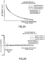
- FIG. 2A illustrates changes in the reference value with respect to the insulation resistance of a case where the capacitance of the detection capacitor increases from an initial capacitance B to a capacitance A, and a case where the capacitance decreases to a capacitance C.
- differences occur in the reference value for each capacitance between a region where the insulation resistance is low and a region where the insulation resistance is high, and such differences are remarkably large in the region where the insulation resistance is low.
- FIG. 2B illustrates a detection error in a case where the insulation resistance is calculated with a standard conversion map corresponding to the initial capacitance B, based on the reference value that has been obtained in each case of the capacitance A, the capacitance B, and the capacitance C.
- the differences in the reference value depending on the capacitance are obvious, and the ratio of the error to the true insulation resistance increases, and the detection error is extremely large.
- the error becomes zero at a resistance value Rt at which the insulation resistance is equal to the charging resistor.
- the insulation resistance becomes lower than it the error becomes abruptly worse, and the calculation accuracy decreases.
- the current capacitance of the detection capacitor C1 is estimated, and the conversion map 140 corresponding to the current capacitance of the detection capacitor C1 that has been estimated is referred to.
- the current capacitance of the detection capacitor C1 is not estimated, and the standard conversion map 140 is referred to.
- the conversion map 140 corresponding only to the region where the insulation resistance is decreased except for the standard conversion map 140. Therefore, the storage area for the conversion map 140 in the control device 120 can be saved.
- the current capacitance of the detection capacitor C1 may be estimated, and the conversion map 140 corresponding to the current capacitance of the detection capacitor C1 that has been estimated may be referred to. Accordingly, the calculation accuracy of the insulation resistance can be further improved.
- opening and closing of the switches S1 to S4 are controlled, and the V0, Vc1n, and Vc1p measurements are respectively performed (S101). Then, a reference value is calculated, based on V0, Vc1n, and Vc1p that have been obtained through the measurements (S102).
- Whether there is a possibility that the insulation resistance is decreasing is determined, based on V0, Vc1n, and Vc1p that have been obtained through the measurements (S103). As described above, an error increases when the insulation resistance is lower than the charging resistor. Therefore, for example, a case where V0 ⁇ (Vc1n + Vc1p) is established can be considered as an indication that the insulation resistance is decreased.
- the detection capacitor capacitance estimation unit 130 estimates the current capacitance of the detection capacitor C1 (S104). The procedure for estimating the current capacitance of the detection capacitor C1 will be described later.
- the insulation resistance is calculated (S107). After the insulation resistance is calculated, an earth fault is determined, based on whether the insulation resistance that has been obtained is lower than a predetermined reference value (S108).
- the insulation resistance is calculated (S107). After the insulation resistance is calculated, an earth fault is determined, based on whether the insulation resistance that has been obtained is lower than a predetermined reference value (S108).
- the actual capacitance of the detection capacitor C1 at a reference temperature is measured before shipment of the earth fault detection apparatus 100.
- the actual capacitance of the detection capacitor C1 can be calculated by, for example, discharging the charged detection capacitor C1 for a predetermined time and measuring a change in charging voltage before and after the discharge.
- the estimated capacitance of the detection capacitor C1 for each ambient temperature is actually measured or theoretically obtained together with the actual capacitance, and is written as a capacitance table in a storage area in the control device 120 that can be referred to by the detection capacitor capacitance estimation unit 130.
- a calculation formula or the like for calculating the present capacitance of the detection capacitor C1 from the ambient temperature may be written.
- the ambient temperature of the detection capacitor C1 is acquired with use of the thermometer TM131 (S201). Then, the capacitance table that has been written before the shipment is referred to (S202), and the capacitance corresponding to the ambient temperature is estimated as the present capacitance of the detection capacitor C1 (S203).
- the ratio of a charging voltage V2 at the time t2 to a charging voltage V1 at the time t1 depends on the capacitance of the detection capacitor C1. Note that it is assumed that the charging resistor is known and constant.
- the detection capacitor capacitance estimation unit 130 controls openings and closings of the switches S1 to S4, charges and discharges the detection capacitor C1 for a predetermined time, and measures the charging voltage V1 of the detection capacitor at the time of ending the charging and the charging voltage V2 of the detection capacitor at the time of ending the discharging. Then, the current capacitance of the detection capacitor C1 is calculated, based on the charging voltages that have been measured and the resistance related to the discharging time.
- C1 (t2 - t1)/(Rd ⁇ ln (V2/V1)) can be used for calculation, where Rd represents the resistance related to the discharging time.
- the earth fault detection apparatus 100 in the present embodiment estimates the current capacitance of the detection capacitor C1, and calculates the insulation resistance with reference to the conversion map 140 corresponding to the estimated value. Therefore, even when the capacitance of the detection capacitor changes, a decrease in the calculation accuracy of the insulation resistance can be prevented.
- the standard conversion map 140 may be referred to without an estimation of the current capacitance of the detection capacitor C1. Accordingly, the storage area for the conversion map 140 in the control device 120 can be saved.
Landscapes
- Physics & Mathematics (AREA)
- General Physics & Mathematics (AREA)
- Testing Of Short-Circuits, Discontinuities, Leakage, Or Incorrect Line Connections (AREA)
- Electric Propulsion And Braking For Vehicles (AREA)
Applications Claiming Priority (1)
| Application Number | Priority Date | Filing Date | Title |
|---|---|---|---|
| JP2021091491A JP7346004B2 (ja) | 2021-05-31 | 2021-05-31 | 地絡検出装置 |
Publications (2)
| Publication Number | Publication Date |
|---|---|
| EP4099028A1 true EP4099028A1 (de) | 2022-12-07 |
| EP4099028B1 EP4099028B1 (de) | 2023-12-13 |
Family
ID=81748694
Family Applications (1)
| Application Number | Title | Priority Date | Filing Date |
|---|---|---|---|
| EP22173806.5A Active EP4099028B1 (de) | 2021-05-31 | 2022-05-17 | Erdschlussdetektionsgerät |
Country Status (4)
| Country | Link |
|---|---|
| US (1) | US11921167B2 (de) |
| EP (1) | EP4099028B1 (de) |
| JP (1) | JP7346004B2 (de) |
| CN (1) | CN115480185B (de) |
Families Citing this family (1)
| Publication number | Priority date | Publication date | Assignee | Title |
|---|---|---|---|---|
| JP7346004B2 (ja) * | 2021-05-31 | 2023-09-19 | 矢崎総業株式会社 | 地絡検出装置 |
Citations (3)
| Publication number | Priority date | Publication date | Assignee | Title |
|---|---|---|---|---|
| US20090289639A1 (en) * | 2008-05-26 | 2009-11-26 | Yoshihiro Kawamura | Insulation measurement method and insulation measurement apparatus |
| JP2014126382A (ja) * | 2012-12-25 | 2014-07-07 | Yazaki Corp | 絶縁状態検出装置 |
| JP2017078587A (ja) | 2015-10-19 | 2017-04-27 | 矢崎総業株式会社 | 電圧検出回路及び電圧検出方法 |
Family Cites Families (8)
| Publication number | Priority date | Publication date | Assignee | Title |
|---|---|---|---|---|
| JP6539441B2 (ja) * | 2014-05-29 | 2019-07-03 | 矢崎総業株式会社 | 出力電流及び地絡抵抗の検出装置 |
| EP3608152B1 (de) * | 2018-08-06 | 2022-06-22 | Ningbo Geely Automobile Research & Development Co. Ltd. | Verfahren zur detektion eines isolierungsfehlers |
| JP7086886B2 (ja) * | 2019-04-03 | 2022-06-20 | 矢崎総業株式会社 | 地絡検出装置 |
| JP7294022B2 (ja) * | 2019-09-19 | 2023-06-20 | 株式会社デンソー | 漏電検出回路 |
| JP7039541B2 (ja) * | 2019-11-15 | 2022-03-22 | 矢崎総業株式会社 | 地絡検出装置 |
| JP7346004B2 (ja) * | 2021-05-31 | 2023-09-19 | 矢崎総業株式会社 | 地絡検出装置 |
| JP7391482B2 (ja) * | 2021-05-31 | 2023-12-05 | 矢崎総業株式会社 | 地絡検出装置 |
| JP7395240B2 (ja) * | 2021-08-06 | 2023-12-11 | 矢崎総業株式会社 | 地絡検出装置 |
-
2021
- 2021-05-31 JP JP2021091491A patent/JP7346004B2/ja active Active
-
2022
- 2022-05-17 EP EP22173806.5A patent/EP4099028B1/de active Active
- 2022-05-24 US US17/752,178 patent/US11921167B2/en active Active
- 2022-05-30 CN CN202210601649.3A patent/CN115480185B/zh active Active
Patent Citations (3)
| Publication number | Priority date | Publication date | Assignee | Title |
|---|---|---|---|---|
| US20090289639A1 (en) * | 2008-05-26 | 2009-11-26 | Yoshihiro Kawamura | Insulation measurement method and insulation measurement apparatus |
| JP2014126382A (ja) * | 2012-12-25 | 2014-07-07 | Yazaki Corp | 絶縁状態検出装置 |
| JP2017078587A (ja) | 2015-10-19 | 2017-04-27 | 矢崎総業株式会社 | 電圧検出回路及び電圧検出方法 |
Also Published As
| Publication number | Publication date |
|---|---|
| US11921167B2 (en) | 2024-03-05 |
| US20220381850A1 (en) | 2022-12-01 |
| JP2022183938A (ja) | 2022-12-13 |
| CN115480185B (zh) | 2025-08-19 |
| EP4099028B1 (de) | 2023-12-13 |
| JP7346004B2 (ja) | 2023-09-19 |
| CN115480185A (zh) | 2022-12-16 |
Similar Documents
| Publication | Publication Date | Title |
|---|---|---|
| US11327124B2 (en) | Ground fault detection apparatus | |
| US9874595B2 (en) | Insulation detecting device | |
| US10611243B2 (en) | Ground fault detection apparatus | |
| US8447544B2 (en) | Method and apparatus for detecting state of charge of battery | |
| EP2360485B1 (de) | Batterieverwaltungssystem und Antriebsverfahren dafür | |
| US20150303532A1 (en) | Battery System and Associated Method for Determining the Internal Resistance of Battery Cells or Battery Modules of Said Battery System | |
| US20190086464A1 (en) | Ground fault detection apparatus | |
| CN110895312B (zh) | 接地故障检测设备 | |
| US11714140B2 (en) | Ground fault detection device | |
| EP3822109B1 (de) | Erdschlussdetektionsvorrichtung | |
| US11133533B2 (en) | Differential voltage measurement device | |
| US12365264B2 (en) | Voltage measurement method and operating method for a vehicle on-board power supply system | |
| EP4099027B1 (de) | Erdschlussdetektionsgerät | |
| US20200386827A1 (en) | Ground fault detection apparatus | |
| EP4099028B1 (de) | Erdschlussdetektionsgerät | |
| US11187759B2 (en) | Ground fault detection device | |
| US20250076409A1 (en) | Ground fault detection apparatus, control method thereof, and control program |
Legal Events
| Date | Code | Title | Description |
|---|---|---|---|
| PUAI | Public reference made under article 153(3) epc to a published international application that has entered the european phase |
Free format text: ORIGINAL CODE: 0009012 |
|
| STAA | Information on the status of an ep patent application or granted ep patent |
Free format text: STATUS: REQUEST FOR EXAMINATION WAS MADE |
|
| 17P | Request for examination filed |
Effective date: 20220517 |
|
| AK | Designated contracting states |
Kind code of ref document: A1 Designated state(s): AL AT BE BG CH CY CZ DE DK EE ES FI FR GB GR HR HU IE IS IT LI LT LU LV MC MK MT NL NO PL PT RO RS SE SI SK SM TR |
|
| RBV | Designated contracting states (corrected) |
Designated state(s): AL AT BE BG CH CY CZ DE DK EE ES FI FR GB GR HR HU IE IS IT LI LT LU LV MC MK MT NL NO PL PT RO RS SE SI SK SM TR |
|
| RAP3 | Party data changed (applicant data changed or rights of an application transferred) |
Owner name: YAZAKI CORPORATION |
|
| GRAP | Despatch of communication of intention to grant a patent |
Free format text: ORIGINAL CODE: EPIDOSNIGR1 |
|
| STAA | Information on the status of an ep patent application or granted ep patent |
Free format text: STATUS: GRANT OF PATENT IS INTENDED |
|
| GRAS | Grant fee paid |
Free format text: ORIGINAL CODE: EPIDOSNIGR3 |
|
| INTG | Intention to grant announced |
Effective date: 20231013 |
|
| GRAA | (expected) grant |
Free format text: ORIGINAL CODE: 0009210 |
|
| STAA | Information on the status of an ep patent application or granted ep patent |
Free format text: STATUS: THE PATENT HAS BEEN GRANTED |
|
| AK | Designated contracting states |
Kind code of ref document: B1 Designated state(s): AL AT BE BG CH CY CZ DE DK EE ES FI FR GB GR HR HU IE IS IT LI LT LU LV MC MK MT NL NO PL PT RO RS SE SI SK SM TR |
|
| REG | Reference to a national code |
Ref country code: GB Ref legal event code: FG4D |
|
| REG | Reference to a national code |
Ref country code: CH Ref legal event code: EP |
|
| REG | Reference to a national code |
Ref country code: DE Ref legal event code: R096 Ref document number: 602022001277 Country of ref document: DE |
|
| REG | Reference to a national code |
Ref country code: IE Ref legal event code: FG4D |
|
| PG25 | Lapsed in a contracting state [announced via postgrant information from national office to epo] |
Ref country code: GR Free format text: LAPSE BECAUSE OF FAILURE TO SUBMIT A TRANSLATION OF THE DESCRIPTION OR TO PAY THE FEE WITHIN THE PRESCRIBED TIME-LIMIT Effective date: 20240314 |
|
| REG | Reference to a national code |
Ref country code: LT Ref legal event code: MG9D |
|
| PG25 | Lapsed in a contracting state [announced via postgrant information from national office to epo] |
Ref country code: LT Free format text: LAPSE BECAUSE OF FAILURE TO SUBMIT A TRANSLATION OF THE DESCRIPTION OR TO PAY THE FEE WITHIN THE PRESCRIBED TIME-LIMIT Effective date: 20231213 |
|
| REG | Reference to a national code |
Ref country code: NL Ref legal event code: MP Effective date: 20231213 |
|
| PG25 | Lapsed in a contracting state [announced via postgrant information from national office to epo] |
Ref country code: ES Free format text: LAPSE BECAUSE OF FAILURE TO SUBMIT A TRANSLATION OF THE DESCRIPTION OR TO PAY THE FEE WITHIN THE PRESCRIBED TIME-LIMIT Effective date: 20231213 |
|
| PG25 | Lapsed in a contracting state [announced via postgrant information from national office to epo] |
Ref country code: LT Free format text: LAPSE BECAUSE OF FAILURE TO SUBMIT A TRANSLATION OF THE DESCRIPTION OR TO PAY THE FEE WITHIN THE PRESCRIBED TIME-LIMIT Effective date: 20231213 Ref country code: GR Free format text: LAPSE BECAUSE OF FAILURE TO SUBMIT A TRANSLATION OF THE DESCRIPTION OR TO PAY THE FEE WITHIN THE PRESCRIBED TIME-LIMIT Effective date: 20240314 Ref country code: ES Free format text: LAPSE BECAUSE OF FAILURE TO SUBMIT A TRANSLATION OF THE DESCRIPTION OR TO PAY THE FEE WITHIN THE PRESCRIBED TIME-LIMIT Effective date: 20231213 Ref country code: BG Free format text: LAPSE BECAUSE OF FAILURE TO SUBMIT A TRANSLATION OF THE DESCRIPTION OR TO PAY THE FEE WITHIN THE PRESCRIBED TIME-LIMIT Effective date: 20240313 |
|
| REG | Reference to a national code |
Ref country code: AT Ref legal event code: MK05 Ref document number: 1640874 Country of ref document: AT Kind code of ref document: T Effective date: 20231213 |
|
| PG25 | Lapsed in a contracting state [announced via postgrant information from national office to epo] |
Ref country code: NL Free format text: LAPSE BECAUSE OF FAILURE TO SUBMIT A TRANSLATION OF THE DESCRIPTION OR TO PAY THE FEE WITHIN THE PRESCRIBED TIME-LIMIT Effective date: 20231213 |
|
| PG25 | Lapsed in a contracting state [announced via postgrant information from national office to epo] |
Ref country code: SE Free format text: LAPSE BECAUSE OF FAILURE TO SUBMIT A TRANSLATION OF THE DESCRIPTION OR TO PAY THE FEE WITHIN THE PRESCRIBED TIME-LIMIT Effective date: 20231213 Ref country code: RS Free format text: LAPSE BECAUSE OF FAILURE TO SUBMIT A TRANSLATION OF THE DESCRIPTION OR TO PAY THE FEE WITHIN THE PRESCRIBED TIME-LIMIT Effective date: 20231213 Ref country code: NO Free format text: LAPSE BECAUSE OF FAILURE TO SUBMIT A TRANSLATION OF THE DESCRIPTION OR TO PAY THE FEE WITHIN THE PRESCRIBED TIME-LIMIT Effective date: 20240313 Ref country code: NL Free format text: LAPSE BECAUSE OF FAILURE TO SUBMIT A TRANSLATION OF THE DESCRIPTION OR TO PAY THE FEE WITHIN THE PRESCRIBED TIME-LIMIT Effective date: 20231213 Ref country code: LV Free format text: LAPSE BECAUSE OF FAILURE TO SUBMIT A TRANSLATION OF THE DESCRIPTION OR TO PAY THE FEE WITHIN THE PRESCRIBED TIME-LIMIT Effective date: 20231213 Ref country code: HR Free format text: LAPSE BECAUSE OF FAILURE TO SUBMIT A TRANSLATION OF THE DESCRIPTION OR TO PAY THE FEE WITHIN THE PRESCRIBED TIME-LIMIT Effective date: 20231213 |
|
| PG25 | Lapsed in a contracting state [announced via postgrant information from national office to epo] |
Ref country code: IS Free format text: LAPSE BECAUSE OF FAILURE TO SUBMIT A TRANSLATION OF THE DESCRIPTION OR TO PAY THE FEE WITHIN THE PRESCRIBED TIME-LIMIT Effective date: 20240413 |
|
| PG25 | Lapsed in a contracting state [announced via postgrant information from national office to epo] |
Ref country code: CZ Free format text: LAPSE BECAUSE OF FAILURE TO SUBMIT A TRANSLATION OF THE DESCRIPTION OR TO PAY THE FEE WITHIN THE PRESCRIBED TIME-LIMIT Effective date: 20231213 Ref country code: AT Free format text: LAPSE BECAUSE OF FAILURE TO SUBMIT A TRANSLATION OF THE DESCRIPTION OR TO PAY THE FEE WITHIN THE PRESCRIBED TIME-LIMIT Effective date: 20231213 |
|
| PG25 | Lapsed in a contracting state [announced via postgrant information from national office to epo] |
Ref country code: SK Free format text: LAPSE BECAUSE OF FAILURE TO SUBMIT A TRANSLATION OF THE DESCRIPTION OR TO PAY THE FEE WITHIN THE PRESCRIBED TIME-LIMIT Effective date: 20231213 |
|
| PG25 | Lapsed in a contracting state [announced via postgrant information from national office to epo] |
Ref country code: SM Free format text: LAPSE BECAUSE OF FAILURE TO SUBMIT A TRANSLATION OF THE DESCRIPTION OR TO PAY THE FEE WITHIN THE PRESCRIBED TIME-LIMIT Effective date: 20231213 Ref country code: SK Free format text: LAPSE BECAUSE OF FAILURE TO SUBMIT A TRANSLATION OF THE DESCRIPTION OR TO PAY THE FEE WITHIN THE PRESCRIBED TIME-LIMIT Effective date: 20231213 Ref country code: RO Free format text: LAPSE BECAUSE OF FAILURE TO SUBMIT A TRANSLATION OF THE DESCRIPTION OR TO PAY THE FEE WITHIN THE PRESCRIBED TIME-LIMIT Effective date: 20231213 Ref country code: IT Free format text: LAPSE BECAUSE OF FAILURE TO SUBMIT A TRANSLATION OF THE DESCRIPTION OR TO PAY THE FEE WITHIN THE PRESCRIBED TIME-LIMIT Effective date: 20231213 Ref country code: IS Free format text: LAPSE BECAUSE OF FAILURE TO SUBMIT A TRANSLATION OF THE DESCRIPTION OR TO PAY THE FEE WITHIN THE PRESCRIBED TIME-LIMIT Effective date: 20240413 Ref country code: EE Free format text: LAPSE BECAUSE OF FAILURE TO SUBMIT A TRANSLATION OF THE DESCRIPTION OR TO PAY THE FEE WITHIN THE PRESCRIBED TIME-LIMIT Effective date: 20231213 Ref country code: CZ Free format text: LAPSE BECAUSE OF FAILURE TO SUBMIT A TRANSLATION OF THE DESCRIPTION OR TO PAY THE FEE WITHIN THE PRESCRIBED TIME-LIMIT Effective date: 20231213 Ref country code: AT Free format text: LAPSE BECAUSE OF FAILURE TO SUBMIT A TRANSLATION OF THE DESCRIPTION OR TO PAY THE FEE WITHIN THE PRESCRIBED TIME-LIMIT Effective date: 20231213 |
|
| PG25 | Lapsed in a contracting state [announced via postgrant information from national office to epo] |
Ref country code: PL Free format text: LAPSE BECAUSE OF FAILURE TO SUBMIT A TRANSLATION OF THE DESCRIPTION OR TO PAY THE FEE WITHIN THE PRESCRIBED TIME-LIMIT Effective date: 20231213 Ref country code: PT Free format text: LAPSE BECAUSE OF FAILURE TO SUBMIT A TRANSLATION OF THE DESCRIPTION OR TO PAY THE FEE WITHIN THE PRESCRIBED TIME-LIMIT Effective date: 20240415 |
|
| PG25 | Lapsed in a contracting state [announced via postgrant information from national office to epo] |
Ref country code: PT Free format text: LAPSE BECAUSE OF FAILURE TO SUBMIT A TRANSLATION OF THE DESCRIPTION OR TO PAY THE FEE WITHIN THE PRESCRIBED TIME-LIMIT Effective date: 20240415 Ref country code: PL Free format text: LAPSE BECAUSE OF FAILURE TO SUBMIT A TRANSLATION OF THE DESCRIPTION OR TO PAY THE FEE WITHIN THE PRESCRIBED TIME-LIMIT Effective date: 20231213 |
|
| REG | Reference to a national code |
Ref country code: DE Ref legal event code: R097 Ref document number: 602022001277 Country of ref document: DE |
|
| PG25 | Lapsed in a contracting state [announced via postgrant information from national office to epo] |
Ref country code: DK Free format text: LAPSE BECAUSE OF FAILURE TO SUBMIT A TRANSLATION OF THE DESCRIPTION OR TO PAY THE FEE WITHIN THE PRESCRIBED TIME-LIMIT Effective date: 20231213 |
|
| PLBE | No opposition filed within time limit |
Free format text: ORIGINAL CODE: 0009261 |
|
| STAA | Information on the status of an ep patent application or granted ep patent |
Free format text: STATUS: NO OPPOSITION FILED WITHIN TIME LIMIT |
|
| PG25 | Lapsed in a contracting state [announced via postgrant information from national office to epo] |
Ref country code: SI Free format text: LAPSE BECAUSE OF FAILURE TO SUBMIT A TRANSLATION OF THE DESCRIPTION OR TO PAY THE FEE WITHIN THE PRESCRIBED TIME-LIMIT Effective date: 20231213 |
|
| PG25 | Lapsed in a contracting state [announced via postgrant information from national office to epo] |
Ref country code: SI Free format text: LAPSE BECAUSE OF FAILURE TO SUBMIT A TRANSLATION OF THE DESCRIPTION OR TO PAY THE FEE WITHIN THE PRESCRIBED TIME-LIMIT Effective date: 20231213 Ref country code: DK Free format text: LAPSE BECAUSE OF FAILURE TO SUBMIT A TRANSLATION OF THE DESCRIPTION OR TO PAY THE FEE WITHIN THE PRESCRIBED TIME-LIMIT Effective date: 20231213 |
|
| 26N | No opposition filed |
Effective date: 20240916 |
|
| PG25 | Lapsed in a contracting state [announced via postgrant information from national office to epo] |
Ref country code: MC Free format text: LAPSE BECAUSE OF FAILURE TO SUBMIT A TRANSLATION OF THE DESCRIPTION OR TO PAY THE FEE WITHIN THE PRESCRIBED TIME-LIMIT Effective date: 20231213 |
|
| PG25 | Lapsed in a contracting state [announced via postgrant information from national office to epo] |
Ref country code: LU Free format text: LAPSE BECAUSE OF NON-PAYMENT OF DUE FEES Effective date: 20240517 |
|
| PG25 | Lapsed in a contracting state [announced via postgrant information from national office to epo] |
Ref country code: MC Free format text: LAPSE BECAUSE OF FAILURE TO SUBMIT A TRANSLATION OF THE DESCRIPTION OR TO PAY THE FEE WITHIN THE PRESCRIBED TIME-LIMIT Effective date: 20231213 Ref country code: LU Free format text: LAPSE BECAUSE OF NON-PAYMENT OF DUE FEES Effective date: 20240517 |
|
| REG | Reference to a national code |
Ref country code: BE Ref legal event code: MM Effective date: 20240531 |
|
| PG25 | Lapsed in a contracting state [announced via postgrant information from national office to epo] |
Ref country code: IE Free format text: LAPSE BECAUSE OF NON-PAYMENT OF DUE FEES Effective date: 20240517 |
|
| PG25 | Lapsed in a contracting state [announced via postgrant information from national office to epo] |
Ref country code: BE Free format text: LAPSE BECAUSE OF NON-PAYMENT OF DUE FEES Effective date: 20240531 |
|
| PG25 | Lapsed in a contracting state [announced via postgrant information from national office to epo] |
Ref country code: FR Free format text: LAPSE BECAUSE OF NON-PAYMENT OF DUE FEES Effective date: 20240531 |
|
| PGFP | Annual fee paid to national office [announced via postgrant information from national office to epo] |
Ref country code: DE Payment date: 20250402 Year of fee payment: 4 |
|
| PG25 | Lapsed in a contracting state [announced via postgrant information from national office to epo] |
Ref country code: CY Free format text: LAPSE BECAUSE OF FAILURE TO SUBMIT A TRANSLATION OF THE DESCRIPTION OR TO PAY THE FEE WITHIN THE PRESCRIBED TIME-LIMIT; INVALID AB INITIO Effective date: 20220517 |
|
| PG25 | Lapsed in a contracting state [announced via postgrant information from national office to epo] |
Ref country code: HU Free format text: LAPSE BECAUSE OF FAILURE TO SUBMIT A TRANSLATION OF THE DESCRIPTION OR TO PAY THE FEE WITHIN THE PRESCRIBED TIME-LIMIT; INVALID AB INITIO Effective date: 20220517 |
|
| PG25 | Lapsed in a contracting state [announced via postgrant information from national office to epo] |
Ref country code: FI Free format text: LAPSE BECAUSE OF FAILURE TO SUBMIT A TRANSLATION OF THE DESCRIPTION OR TO PAY THE FEE WITHIN THE PRESCRIBED TIME-LIMIT Effective date: 20231213 |
|
| REG | Reference to a national code |
Ref country code: CH Ref legal event code: H13 Free format text: ST27 STATUS EVENT CODE: U-0-0-H10-H13 (AS PROVIDED BY THE NATIONAL OFFICE) Effective date: 20251223 |
|
| PG25 | Lapsed in a contracting state [announced via postgrant information from national office to epo] |
Ref country code: CH Free format text: LAPSE BECAUSE OF NON-PAYMENT OF DUE FEES Effective date: 20250531 |