EP4098604B1 - Mehrschichtige taschenfederstranganordnung - Google Patents
Mehrschichtige taschenfederstranganordnung Download PDFInfo
- Publication number
- EP4098604B1 EP4098604B1 EP21177398.1A EP21177398A EP4098604B1 EP 4098604 B1 EP4098604 B1 EP 4098604B1 EP 21177398 A EP21177398 A EP 21177398A EP 4098604 B1 EP4098604 B1 EP 4098604B1
- Authority
- EP
- European Patent Office
- Prior art keywords
- strand
- pocketed
- spring
- seam portion
- pocketed spring
- Prior art date
- Legal status (The legal status is an assumption and is not a legal conclusion. Google has not performed a legal analysis and makes no representation as to the accuracy of the status listed.)
- Active
Links
Images



Classifications
-
- B—PERFORMING OPERATIONS; TRANSPORTING
- B68—SADDLERY; UPHOLSTERY
- B68G—METHODS, EQUIPMENT, OR MACHINES FOR USE IN UPHOLSTERING; UPHOLSTERY NOT OTHERWISE PROVIDED FOR
- B68G9/00—Placing upholstery springs in pockets; Fitting springs in upholstery
-
- A—HUMAN NECESSITIES
- A47—FURNITURE; DOMESTIC ARTICLES OR APPLIANCES; COFFEE MILLS; SPICE MILLS; SUCTION CLEANERS IN GENERAL
- A47C—CHAIRS; SOFAS; BEDS
- A47C27/00—Spring, stuffed or fluid mattresses or cushions specially adapted for chairs, beds or sofas
- A47C27/04—Spring, stuffed or fluid mattresses or cushions specially adapted for chairs, beds or sofas with spring inlays
- A47C27/06—Spring inlays or spring units therefor
- A47C27/063—Spring inlays or spring units therefor wrapped or otherwise protected
- A47C27/064—Pocketed springs
-
- B—PERFORMING OPERATIONS; TRANSPORTING
- B21—MECHANICAL METAL-WORKING WITHOUT ESSENTIALLY REMOVING MATERIAL; PUNCHING METAL
- B21F—WORKING OR PROCESSING OF METAL WIRE
- B21F33/00—Tools or devices specially designed for handling or processing wire fabrics or the like
-
- B—PERFORMING OPERATIONS; TRANSPORTING
- B68—SADDLERY; UPHOLSTERY
- B68G—METHODS, EQUIPMENT, OR MACHINES FOR USE IN UPHOLSTERING; UPHOLSTERY NOT OTHERWISE PROVIDED FOR
- B68G15/00—Auxiliary devices and tools specially for upholstery
-
- B—PERFORMING OPERATIONS; TRANSPORTING
- B23—MACHINE TOOLS; METAL-WORKING NOT OTHERWISE PROVIDED FOR
- B23K—SOLDERING OR UNSOLDERING; WELDING; CLADDING OR PLATING BY SOLDERING OR WELDING; CUTTING BY APPLYING HEAT LOCALLY, e.g. FLAME CUTTING; WORKING BY LASER BEAM
- B23K20/00—Non-electric welding by applying impact or other pressure, with or without the application of heat, e.g. cladding or plating
- B23K20/10—Non-electric welding by applying impact or other pressure, with or without the application of heat, e.g. cladding or plating making use of vibrations, e.g. ultrasonic welding
Definitions
- the present invention relates to a machine for assembly of multi-layer strands of pocketed springs and to a method of assembling multi-layer strands of pocketed springs.
- DE 10 2010 060 B4 describes a spring core having a first layer of spring elements and a second layer of spring elements.
- the two layers each consist of rows of spring elements which are fixed to each other. Further, the two layers may be fixed to each other, e.g., by gluing.
- the spring elements of the two layers may have different characteristics, which allows for tailoring overall characteristics of the spring core.
- WO 2015/004154 A1 describes a method of manufacturing a spring core in which multiple strands of pocketed springs are automatically joined on top of each other by gluing. However, such joining by gluing may alter characteristics of the pocket material in an undesirable manner, e.g., concerning flexibility or permeability.
- the present invention provides a machine according to claim 1, a method according to claim 10, and a spring core unit according to claim 13.
- the dependent claims define further embodiments.
- an embodiment of the invention provides a machine for forming a multi-layer strand of pocketed springs.
- the machine comprises an alignment mechanism for receiving a first strand of pocketed springs and a second strand of pocketed springs.
- the alignment mechanism is configured to align a first pocketed spring of the first strand in a coaxial manner with a second pocketed spring of the second strand.
- the alignment is performed in such a way that a first seam portion of pocket material at an end of the first pocketed spring overlaps with a second seam portion at an opposing end of the second pocketed spring.
- the seam portions may for example be so-called pig ears which are formed in the pocket material when closing a pocket with enclosed spring.
- the machine comprises a welding mechanism configured to weld the first seam portion to the second seam portion. Accordingly, a connection between the first strand and the second strand may be formed in an efficient manner by welding, without requiring additional material or chemicals to form the connection.
- the welding mechanism is based on welding of the first seam portion and the second seam portion between an anvil and a welding tool.
- the welding mechanism may be based on ultrasonic welding, and the welding tool can be an ultrasonic horn.
- the anvil engages between the first pocketed spring and an adjacent pocketed spring of the first strand and between the second pocketed spring and an adjacent pocketed spring of the second strand. In this way, the anvil may support the alignment of the first pocketed spring and the second pocketed spring.
- the anvil is mounted on a wheel and rotation of the wheel causes transport of the first strand and the second strand between an input and an output of the machine.
- the anvil may efficiently contribute to transport of the first strand and the second strand into the machine and to transport of the multi-layer strand out of the machine.
- the anvil will move along a circular trajectory, which enables efficiently combining movement of the anvil to engage between the adjacent first and second pocketed springs, to transport the strand while the anvil is engaged between the adjacent first and second pocketed springs, and to then disengage from between the adjacent first and second pocketed springs.
- the machine further comprises support elements which are mounted on the wheel.
- the support elements may be configured to engage between the first pocketed spring and an adjacent pocketed spring of the first strand and between the second pocketed spring and an adjacent pocketed spring of the second strand.
- the support elements may be adjustable, e.g., in a radial direction of the wheel and/or in a circumferential direction of the wheel. In this way, the support elements may be adjusted to accommodate and reliably support different sizes of the first pocketed springs and the second pocketed springs.
- the support elements may comprise a first pair of support elements for the first strand and a second pair of support elements for the second strand.
- a first support element of the first pair may support the first pocketed spring of the first strand, while a second support element of the first pair supports the adjacent pocketed spring of the first strand.
- a first support element of the second pair may support the first pocketed spring of the second strand, while a second support element of the second pair supports the adjacent pocketed spring of the second strand.
- the support elements may have a shape of blades extending parallel to the axis of the pocketed spring elements.
- the alignment mechanism is configured to align each of multiple first pocketed springs of the first strand with a corresponding one of multiple pocketed springs of the second strand so that, for each pair of first pocketed spring and corresponding second pocketed spring, a first seam portion of pocket material at an end of the first pocketed spring overlaps with a second seam portion at an end of the corresponding second pocketed spring.
- multiple pairs of aligned first and second pocketed springs may be formed before welding the overlapping seam portions.
- the welding process may be parallelized.
- the welding mechanism may include multiple welding tools cooperating with multiple anvils.
- Each of the multiple welding tools may be configured to cooperate with one of the anvils to weld the overlapping first and second seam portions of a corresponding pair of the aligned first and second pocketed springs.
- the anvils may engage between adjacent pairs of the aligned first and second pocketed springs, and the anvils may be mounted on a wheel. As explained above, rotation of the wheel may cause transport of the first strand and the second strand between an input and an output of the machine.
- the welding tools are each provided with a drive mechanism for driving movement of the welding tool with respect to the corresponding anvil.
- the movements of the welding tools may be along radial directions with respect to a center of rotation of the wheel.
- the alignment mechanism comprises a first guide member for guiding transport of the first strand of pocketed springs towards the welding mechanism, and a second guide member for guiding transport of the second strand of pocketed springs towards the welding mechanism.
- the first guide member and the second guide member may converging at an angle towards a position where the first pocketed spring of the first strand and the second pocketed spring of the second strand become aligned. In this way, it can be achieved that the first and second seam portions are brought to overlap in a precise and controlled manner.
- a further embodiment of the invention provides a method of forming a multi-layer strand of pocketed springs.
- the method may for example be performed by the machine according to any of the above embodiments.
- the method comprise receiving a first strand of pocketed springs and a second strand of pocketed springs. While being received, the first strand and the second strand can for example be guided by the above-mentioned guide elements.
- the method comprises aligning a first pocketed spring of the first strand in a coaxial manner with a second pocketed spring of the second strand so that a first seam portion of pocket material at an end of the first pocketed spring overlaps with a second seam portion at an end of the second pocketed spring, e.g., using the above-mentioned alignment mechanism. Further, the method comprises welding the first seam portion to the second seam portion, e.g., using the above-mentioned welding mechanism.
- the welding of the first and second seam portions may be based on welding of the first seam portion and the second seam portion between an anvil and a welding tool.
- the anvil may engage between the first pocketed spring and an adjacent pocketed spring of the first strand and between the second pocketed spring and an adjacent pocketed spring of the second strand.
- the anvil may be mounted on a wheel and the method may further comprises rotation of the wheel to transport of the first strand and the second strand.
- the method may comprise aligning each of multiple first pocketed springs of the first strand with a corresponding one of multiple pocketed springs of the second strand so that, for each pair of first pocketed spring and corresponding second pocketed spring, a first seam portion of pocket material at an end of the first pocketed spring overlaps with a second seam portion at an end of the corresponding second pocketed spring. Then, by using multiple welding tools cooperating with multiple anvils, the overlapping first and second seam portions of multiple pairs of the aligned first and second pocketed springs may be welded together.
- a further embodiment of the invention provides a spring core unit.
- the spring core unit may be produced by the above-mentioned machine or method.
- the spring core unit comprises at least one multi-layer strand of pocketed springs.
- the multi-layer strand comprises at least a first strand of pocketed springs and a second strand of pocketed springs.
- At least one first pocketed spring of the first strand is aligned in a coaxial manner with a corresponding second pocketed spring of the second strand so that a first seam portion of pocket material at an end of the first pocketed spring overlaps with a second seam portion at an opposing end of the corresponding second pocketed spring.
- the first seam portion is welded to the second seam portion to connect the first strand to the second strand.
- the spring core unit may comprise multiple multi-layer strands of pocketed springs, with each of the multi-layer strands comprising at least a first strand of pocketed springs and a second strand of pocketed springs.
- each of the multi-layer strands at least one first pocketed spring of the first strand is aligned in a coaxial manner with a corresponding second pocketed spring of the second strand so that a first seam portion of pocket material at an end of the first pocketed spring overlaps with a second seam portion at an end of the corresponding second pocketed spring, and the first seam portion is welded to the second seam portion to connect the first strand to the second strand.
- the multi-layer strands may differ from each other with respect to at least one characteristic of the pocketed springs of the first strand and/or at least one characteristic of the pocketed springs of the second strand.
- the multi-layer strands could differ with respect to one or more characteristics selected from a height of the pocketed springs of the first strand, a height of the pocketed springs of the second strand, a spring constant of the pocketed springs of the first strand, a spring constant of the pocketed springs of the second strand, a shape of the pocketed springs of the first strand, and a shape of the pocketed springs of the second strand.
- the spring core unit may be efficiently provided with multiple zones having tailored characteristics.
- at least some of the multi-layer strands could differ from each other with respect to the number of layers, i.e., the number of strands of pocketed springs connected on top of each other.
- the spring core unit may comprise at least one multi-layer strand of pocketed springs which comprises a first strand of pocketed springs, a second strand of pocketed springs, and a third strand of pocketed springs. These may be connected in the same way as described above for the first strand and second strand.
- At least one first pocketed spring of the first strand is aligned in a coaxial manner with a corresponding second pocketed spring of the second strand and a corresponding third pocketed spring of the third strand, so that a first seam portion of pocket material at an end of the first pocketed spring overlaps with a second seam portion at an end of the corresponding second pocketed spring and a third seam portion of pocket material at another end of the corresponding second pocketed spring overlaps with a fourth seam portion at an end of the corresponding third pocketed spring.
- the first seam portion is welded to the second seam portion to connect the first strand to the second strand and the third seam portion is welded to the fourth seam portion to connect the second strand to the third strand.
- the at least one multi-layer strand could also be provided with four or more layers formed by strands of pocketed springs connected on top of each other.
- the spring core may for example be used in a mattress or other type of bedding or seating product, e.g., a boxspring or a sofa.
- the pocketed springs considered in the illustrated examples may correspond to various types of spring enclosed by a pocket material, e.g., coil springs formed of steel, another metal, or of a plastic material. Further, the springs could also consist of elastic foam or gel material, e.g., in the form of pegs.
- the pocket material may be a nonwoven fabric.
- the pocket material may be welded along at least one seam to form the pocket.
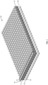
- Fig. 1 schematically illustrates a multi-layer spring core 50, e.g., to be used in a mattress.
- the spring core 50 includes an upper layer 51 of pocketed springs 21 and a lower layer 52 of pocketed springs 22.
- the pocketed springs 21 of the upper layer 51 and the pocketed springs 22 of the lower layer 52 may have different characteristics, e.g., hardness or height. In this way, the overall characteristics of the spring core 50 can be tailored in a precise and flexible manner.
- the spring core 50 is formed of multiple rows of pocketed springs 21, 22. Each of these rows correspond to a multi-layer strand 10 of pocketed springs 21, 22.
- the spring core 50 is formed by assembling multiple multi-layer strands 10 next to each other. In the illustrated example, these multi-layer strands 10 are assumed to each have the same configuration. However, it would also be possible to form the spring core 50 of multi-layer strands 10 having different configurations, e.g., concerning a heights or types of the pocketed springs 21, 22. Still further, the spring core 50 could also include rows with single layer strands of pocketed springs or rows with multi-layer strands having more than two layers of pocketed springs.
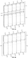
- Figs. 2A and 2B schematically illustrate formation and structure of the multi-layer strand 10.
- the multi-layer strand 10 is formed by connecting a first strand 11 of pocketed springs 21 and a second strand of pocketed springs 22.
- Fig. 2A shows the strands 11, 12 before being connected.
- Fig. 2B shows the strands 11, 12 after being connected to form the multi-layer strand 10.
- each of the pocketed springs 21 of the first strand 11 has seam portions 31 protruding at a bottom end of the pocketed spring 21. These seam portions 31 are located in the region between two adjacent pocketed springs 21 and correspond to so-called pig ears resulting from excess pocket material remaining when forming a seam to close the pockets.
- each of the pocketed springs 22 of the first strand 12 has seam portions 32 protruding at a top end of the pocketed spring 22. These seam portions 32 are located in the region between two adjacent pocketed springs 22 and correspond to pig ears resulting from excess pocket material remaining when forming a seam to close the pockets. As shown in Fig.
- these seam portions 31, 32 are used to connect the first strand 11 and the second strand 12.
- a pocketed spring 21 of the first strand 11 is coaxially aligned with a corresponding pocketed spring 22 of the second strand 12, with the bottom end of the first pocketed spring 21 abutting on the top end of the corresponding pocketed spring 22 of the second strand 12.
- This alignment causes the seam portions 31 of the pocketed springs 21 to overlap with the seam portions 32 of the pocketed springs 22.
- the connection between the first strand 11 and the second strand is formed by welding at least some of the overlapping seam portions 31, 32 to each other, e.g., using ultrasonic welding.
- Fig. 3 schematically illustrates an example of a machine 100 for producing the multi-layer strand 10.
- the machine 100 includes guide elements 111, 111', 112, 112' which receive the first strand 11 and the second strand 12 at an input of the machine and guide the strands 11, 12 towards a welding stage.
- the welding stage includes a set of welding tools 120 which cooperate with a set of anvils 121.
- the welding tools 120 are assumed to be ultrasonic horns. However, utilization of other welding techniques is conceivable as well, e.g., thermal welding.
- the machine includes a output guide element 140.
- the guide elements 111, 111', 112, 112' include a first guide element 111 which guides the first strand 11 and a second guide element 112 for guiding the second strand 12. While being received in the machine, transport of the first strand 11 occurs along the first guide element 111 and transport of the second strand 12 occurs along the second guide element 112.
- the transport paths of the first strand 11 and the second strand 12 in the machine follow curved trajectories which are perpendicular to the axes of the pocketed springs 21, 22. In the illustration of Fig.
- the axes of the pocketed springs 21, 22 are assumed to extend along an x-direction, with the trajectories running parallel to a z-y-plane which is perpendicular to the x-axis.
- the trajectory of the first strand 11 and the trajectory of the second strand 12 have an offset. The size of this offset is set to substantially align the bottom ends of the pocketed springs 21 of the first strand 11 with the top ends of the pocketed springs 22 of the second strand 12.
- first guide element 111 and the second guide element 112 have an angular offset in the z-y plane causing them to converge along the trajectory towards the welding stage.
- an axial offset between a pocketed spring 21 of the first strand 11 and a corresponding pocketed spring 22 of the second strand 12 gradually decreases.
- the trajectories of the first strand 11 and the second strand meet.
- the overlapping seam portions 31, 32 of the pocketed springs 21, 22 become meet so that they can be subsequently welded in the welding stage.
- the guide elements 111, 111', 112, 112' also include outer guide elements 111', 112'. Together with the guide element 111, the outer guide element 111' forms a guide channel for the first strand 11, and together with the guide element 112, the outer guide element 112' forms a guide channel for the second strand 12. In some scenarios, additional guide elements may be provided to limit the guide channels also along the axes of the pocketed springs 21, 22.
- This axial limitation may be set to provide a certain degree of pretension of the pocketed springs 21, 22. Due to this pretension, it can be achieved that the bottom ends of the pocketed springs 21 of the first strand 11 and the top ends of the pocketed springs 22 of the second strand 12 are pushed against each other when they become aligned before entering the welding stage. In this way, alignment of the pocketed springs 21, 22 and overlap of the seam portions 31, 32 can be further improved.
- feeding of the first strand 11 and the second strand 12 may be further assisted by an index wheel mechanism, which may help to provide initial alignment of the pocketed springs 21 of the first strand 11 with the corresponding pocketed springs 22 of the second strand 12 along the strands 11, 12.
- the anvils 121 are mounted with regular angular spacing on a wheel 130.
- the anvils 121 are substantially blade shaped and extend in parallel to the axes of the pocketed springs 21, 22.
- the wheel 130 is provided with a drive 135 for driving rotation of the wheel 130.
- the drive 130 can for example be based on an electric stepper motor.
- the angular spacing and radial position of the anvils 121 on the wheel 130 may be set according to the size of the pocketed springs 21, 22.
- Rotation of the wheel 130 causes the anvils 121 to engage between adjacent pocketed springs 21 first strand 11 and corresponding adjacent pocketed springs 22 of the second strand 12.
- This engagement happens at a point where the pocketed springs 21, 22 leave the guide channels and their transport trajectories tangentially meet the circular trajectory of the anvils 121.
- the engagement of the anvils between the adjacent pocketed springs 21, 22 also contributes to further aligning the pocketed springs 21 of the first strand 11 with the corresponding pocketed springs 22 of the second strand 12.
- rotational movement of the wheel 130 while the anvils 121 are engaged between the adjacent pocketed springs 21, 22 causes transport of the strands 11, 12 into and through the machine 100.
- the wheel 130, with the anvils 121 mounted thereon operates in a similar manner as an index wheel.
- the welding tools 120 are arranged at certain angular positions along a circumference of the wheel 130. These angular positions of the welding tools 120 correspond to angular positions of the anvils 121 on the wheel 130. In the illustrated example, six anvils 121 are mounted on the wheel 130, with a regular angular spacing of 60°. The welding tools 120 are mounted at angular positions corresponding to 0°, 60°, 120°, and 180°. Accordingly, by rotation of the wheel 130, the welding tools 120 can be brought into angular alignment with a correspond number of the anvils 121, and in this rotational position of the wheel 130, welding of the seal portions 31, 32 can be performed in a parallelized manner by substantially simultaneous operation of the multiple welding tools 120.
- each of the welding tools 120 is mounted on a linear drive 125.
- the linear drive 125 is configured to move the welding tool 125 along a radial direction of the wheel 130. Accordingly, when the wheel 130 is in the above-mentioned rotational position where the welding tools 120 are in angular alignment with the anvils 121, the linear drives 125 can be used to move the welding tools 120 towards the respectively aligned anvils 121, bringing the overlapping seam portions 31, 32 between the welding tool 120 and the anvil 121 to perform the welding. After the welding process, the linear drives 125 can be used to retract the welding tools 120 from the anvils 121, so that the wheel 130 can be further rotated for a next welding cycle.
- some components of the machines may be adjustable.
- adjustability may concern the angular positions of the anvils 121 on the wheel 130 and the angular positions of the welding tools 120.
- adjustability may concern the radial position of the anvils 121 on the wheel 130.
- adjustability may concern the positions of the guide elements 111, 111', 112, 112'.
- the adjustability may be based on manual adjustment and/or automated adjustment, e.g., using servo motors or the like.
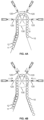
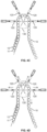
- FIGs. 4A to 4D schematically illustrate operation of the machine 100 when producing the multi-layer strand 10 of pocketed springs 21, 22.
- Figs. 4A, 4B , 4C, and 4D illustrate different stages of an operating cycle of the machine 100.
- an initial setup process may for example involve moving the welding tools 125 to an outermost position, which maximizes free space for other adjustments to be made.
- the radial position of the anvils 121 can be adjusted depending on the size of the pocketed coils 21, 22 and depending on the number of pocketed coils 21, 22 which should be between two adjacent anvils 121. In the illustrated example, this number is two, which means that welding of the seam portions 31, 32 will be performed at every second pocketed spring 21, 22.
- a smaller diameter of the pocketed springs 21, 22 may require positioning the anvils 121 closer to the center of the wheel 130.
- initial feeding of the strands 11, 12 into the machine 100 can be performed.
- the strands 11, 12 can be manually engaged with at least some of the anvils 121 on the wheel 130.
- a fine adjustment of the radial positions of the anvils 121 can be performed.
- the fine adjustment may have the purpose of causing a slight radial compression of the pocketed springs 21, 22 engaged between two anvils 121.
- Such radial compression may help to further enhance the overlap of the seam portions 31, 32 to be welded.
- the guide elements 111, 111', 112, 121 may be adjusted in accordance with the positions of the anvils 121 and the size of the pocketed springs 21, 22.
- the welding tools 120 can be moved back closer to the wheel 130, into an open position which still allows rotation of the wheel 130 with the strands 11, 12 engaged on the anvils 121.
- the machine 100 operates in a cyclic manner, with each cycle involving further transport of the strands 11, 12 through the machine 100 and formation of welds on some of the pocketed springs 21, 22.
- Fig. 4A illustrates an initial phase of the cycle, where a certain pair of a pocketed spring 21 of the first strand 11 is axially aligned with a corresponding pocketed spring 22 of the second strand 12 and enters the welding stage. This pair of aligned pocketed springs 21, 22 is marked by an "x".
- the welding tools 120 are in the outer position and the wheel 130 is rotated to further transport the strands 11, 12 into and through the machine 100, as indicated by the arrows in Fig. 4A.
- Fig. 4B shows a subsequent rotational position of the wheel 130, in which there is again angular alignment of the welding tools 120 and anvils 121.
- the rotational position of the wheel 130 is kept fixed and the welding tools 120 are moved in a radial direction towards the anvils 121, as illustrated by the arrows in Fig. 4B .
- the radial movement of the welding tools 120 is continued until the welding tools 120 each engage with the corresponding anvil 121, with the overlapping seam portions 31, 32 being compressed between the welding tool 120 and the anvil 121, as illustrated in Fig. 4C .
- welding of the overlapping seam portions 31, 32 is performed in a parallelized manner, by substantially simultaneous operation of the multiple welding tools 120.
- this may involve that the overlapping seam portions 31, 32 are spliced together by ultrasonic energy causing friction and heat between the welding tool 120, the fabric of the seam portions 31, 32, and the anvil 121.
- the welding tools 120 are retracted to the open position and the wheel 130 can be further rotated, as illustrated by the arrows in Fig. 4D .
- the operation may then continue with a next cycle, starting from a situation like in Fig. 4A .
- the machine 100 may further be provided with support elements for supporting the pocketed springs 21, 22 while being transported through the welding stage.
- support elements for supporting the pocketed springs 21, 22 while being transported through the welding stage.
- An example of such support elements is schematically illustrated in Figs. 5A, 5B , and 5C .
- support elements 135 are mounted on the wheel 130.
- Fig. 5A shows a perspective view and Fig. 5B shows a plan view for illustrating structure and operation of the support elements 135.
- Fig. 5C shows a sectional view along line A-A of Fig. 5C .
- the support elements 135 engage between adjacent pocketed springs 21 of the first strand and between adjacent pocketed springs 22 of the second strand 22.
- the support elements 135 are substantially blade shaped and extend along a longitudinal axis of the pocketed springs 21, 22, in parallel to a rotation axis of the wheel which corresponds to a radial direction of the wheel 130.
- the support elements 135 are arranged in pairs.
- the support elements 135 include a first pair of support elements 135A.
- the support elements 135A of the first pair are spaced apart with respect to a center position defined by the anvil 121.
- the support elements 135 include a second pair of support elements 135B.
- the support elements 135B of the second pair are spaced apart with respect to a center position defined by the anvil 121. and engage between two adjacent pocketed springs 22 of the first strand 12.
- a first support element 135A of the first pair may support one pocketed spring 21 of the first strand 11, while a second support element 135A of the first pair supports the adjacent pocketed spring 21.
- a first support element 135B of the second pair supports one pocketed spring 22 of the second strand 12, while a second support element 135 of the second pair supports the adjacent pocketed spring 22 of the second strand 12.
- the support elements 135 may be adjustable, e.g., in a radial direction of the wheel 130 and/or in a circumferential direction of the wheel 130. This adjustability may in particular involve that, in a circumferential direction, the distance between the support elements 135 of a pair is adjusted, e.g., depending on the diameter of the pocketed springs 21, 22 to be supported.
- the adjustability of the support elements 135A of the first pair may be independent of the adjustability of the second pair 135B.
- the adjustability ma involve that the support elements 135 are adjustable in the radial direction, e.g., depending of the height of the pocketed springs 21, 22 to be supported.
- Fig. 6 schematically illustrates a liner geometry of the welding stage, where transport of the strands 11, 12 through the welding stage follows a substantially linear trajectory, as indicated by the arrow in Fig. 6 .
- the welding stage includes multiple welding tools 120 which cooperate with multiple anvils 121.
- the example of Fig. 6 assumes that the number of welding tools 120 and the number of anvils 121 is two.
- the welding tools 120 are mounted on linear drives 125 which allow for moving the welding tool 120 towards the trajectory of the strands 11, 12 and towards the corresponding anvil 121.
- the anvils 121 are each mounted on linear drives 122 which allow for moving the welding tool 120 towards the trajectory of the strands 11, 12 and towards the corresponding anvil 121.
- the welding tools 125 and the corresponding anvils 121 can be moved towards each other so that the overlapping seam portions 31, 32 are compressed between the welding tool 120 and the anvil 121 while performing the welding, and the welding tools 125 and the anvils 121 can be retracted from the strands 11, 12 so as to allow transport of the strands 11, 12 through the machine 100.
- transport of the strands 11, 12 into the machine 100 and transport of the multi-layer strand 10 out of the machine 100 can be achieved on the basis of various kinds of transport mechanisms, e.g., one or more indexed wheels and/or one or more conveyor belts.
- Fig. 7 shows a further example of a multi-layer strand 10 in accordance with the illustrated concepts. Similar to the multi-layer strand 10 illustrated in Fig. 2B , the multi-layer strand 10 of Fig. 7 includes layers formed by a first strand 11 of pocketed springs 21 and a second strand of pocketed springs 22, which are connected to each other by welding seam portions protruding at a bottom end of the pocketed springs 21 to seam portions protruding at a top end of the pocketed springs 22, e.g., using ultrasonic welding. Further, the multi-layer strand 10 of Fig. 7 includes a further layer formed by a third strand 13 of pocketed springs 23.
- the third strand 13 is connected to the second strand 12 by welding seam portions protruding at a bottom end of the pocketed springs 22 to seam portions protruding at a top end of the pocketed springs 23, e.g., using ultrasonic welding.
- the seam portions used to connect the first strand 11, the second strand 12, and the third strand 13 may be located in the region between two adjacent pocketed springs 21, 22, 23 and may correspond to pig ears resulting from excess pocket material remaining when forming a seam to close the pockets.
- each pocketed spring 21 of the first strand 11 is aligned in a coaxial manner with a corresponding second pocketed spring 22 of the second strand 12 and a corresponding third pocketed spring 23 of the third strand 13.
- a seam portion of pocket material at a the bottom end of the pocketed springs 21 to overlap with a seam portion at a top end of the corresponding pocketed spring 22 and a seam portion of pocket material at the bottom end of the pocketed springs 22 to overlap with a seam portion at a top end of the corresponding pocketed spring 23.
- the overlapping seam portions are welded together to connect the strands 11, 12, 13 to the multi-layer strand 10.
- the pocketed springs 21 could have a height which differs from the height of the pocketed springs 22 and/or from the height of the pocketed springs 23.
- the pocketed springs 21 could have a spring constant which differs from the spring constant of the pocketed springs 22 and/or from the spring constant of the pocketed springs 23.
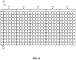
- Fig. 8 shows a further example of a spring core unit 50 which is based on combining multiple multi-layer strands 10 of the illustrated concepts.
- Fig. 8 an example of using the multi-layer strands 10 to form a spring core unit 50 having multiple zones 11, 12, 13, 14, 15, e.g., corresponding to a head section, a shoulder section, a middle section, a leg section, and a feet section, respectively.
- the zones 11, 12, 13, 14, 15 may be formed by combining multi-layer strands 10 of different characteristics.
- the zone 11 could consist of multi-layer strands 10 of a first type
- the zone 12 could consist of multi-layer strands 10 of a second type
- the zone 13 could consist of multi-layer strands 10 of a third type
- the zone 14 could consist of multi-layer strands 10 of a fourth type
- the zone 15 could consist of multi-layer strands 10 of a fifth type.
- the spring core unit 50 could have a symmetrical configuration in which the zone 11 being similar to the zone 15, and the zone 12 being similar to the zone 14.
- at least some of the zones 11, 12, 13, 14, 15 may also include single layer strands of pocketed springs, either in combination or as an alternative to the multi-layer strands 10.
- the spring core unit 50 of Fig. 8 includes multiple multi-layer strands 10 of pocketed springs, which may each be formed as explained above and may for example have a structure as illustrated in Fig. 2B or Fig. 7 .
- at least some of the multi-layer strands 10 may differ from each other, e.g., with respect to at least one characteristic of the pocketed springs used in one or more of the layers and/or with respect to the number of the layers.
- the multi-layer strands 10 could differ with respect to one or more characteristics selected from a height of the pocketed springs of the strand corresponding to a certain layer, a spring constant of the pocketed springs of the strand corresponding to a certain layer, a shape of the pocketed springs of the strand corresponding to a certain layer, or wire gauge of the pocketed springs of the strand corresponding to a certain layer.
- the number of layers could be two, while in other multi-layer strands 10 the number of layers could be three. If there are differences in overall height between such different multi-layer strands 10, these height differences may be compensated by additional elements, e.g., cushions or additional spring elements. Such additional elements may be glued to the spring core unit 50 or may be inserted into the product, e.g., mattress formed of the spring core unit 50.
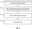
- Fig. 9 shows a flowchart for illustrating a method of forming a multi-layer strand of pocketed springs. The method of Fig. 9 may be performed by the above-described machine 100.
- At block 910 at least a first strand of pocketed springs and a second strand of pocketed springs are received, such as the above-mentioned strands 11, 12, 13 of pocketed springs 21, 22, 23. While being received, the first strand and the second strand can for example be guided by guide elements, such as the above-mentioned guide elements 111, 111', 112, 112'.
- a first pocketed spring of the first strand is aligned in a coaxial manner with a second pocketed spring of the second strand so that a first seam portion of pocket material at an end of the first pocketed spring overlaps with a second seam portion at an end of the second pocketed spring.
- the seam portions may correspond to excess pocket material protruding at the end of the pocketed spring and may be formed when forming a seam to close a pocket of the pocketed springs, such as explained for the above-mentioned pig-ear like seam portions 31, 32.
- the alignment of block 920 can be performed by an alignment mechanism.
- the alignment mechanism may include the above-mentioned guide elements 111, 111', 112, 112' and parts of a transport mechanism for transporting the strands, e.g., an index wheel or the above-mentioned anvils 121 engaging between adjacent pocketed springs 21, 22.
- block 920 may involve aligning each of multiple first pocketed springs of the first strand with a corresponding one of multiple pocketed springs of the second strand so that, for each pair of first pocketed spring and corresponding second pocketed spring, a first seam portion of pocket material at an end of the first pocketed spring overlaps with a second seam portion at an end of the corresponding second pocketed spring.
- the first seam portion is welded to the second seam portion, e.g., using the above-mentioned welding mechanism.
- the welding of the first and second seam portions may be based on welding of the first seam portion and the second seam portion between an anvil and a welding tool, e.g., as explained for the above-mentioned welding tools 125 and anvils 121.
- the welding may be based on ultrasonic welding, and the welding tool may then correspond to an ultrasonic horn.
- the anvil may engage between the first pocketed spring and an adjacent pocketed spring of the first strand and between the second pocketed spring and an adjacent pocketed spring of the second strand.
- the welding of block 930 may be performed using multiple welding tools cooperating with multiple anvils.
- the overlapping first and second seam portions of multiple pairs of the aligned first and second pocketed springs may be welded together in a parallelized or substantially simultaneous manner.
- the first strand and the second strand may be transported.
- this may involve that the anvil is mounted on a wheel and rotation of the wheel causes transport of the first strand and the second strand due to engagement of the anvil between adjacent pocketed springs of the first strand and between adjacent pocketed springs of the second strand.
- the anvil mounted on the wheel may operate similar to an index wheel to transport the first and second strand.
- the method of Fig. 9 may also be used to form a multi-layer strand having more than two layers, e.g., three layers. This may for example be achieved by aligning more than two pocketed springs on top of each other and then connecting the overlapping seam portions at the interfaces between the aligned pocketed springs of different strands. Further, more than two layers could also of the multi-layer strand could also be achieved by using the method of Fig. 9 in an iterative manner, e.g., by first forming a multi-layer strand having two layers and then using the method of Fig. 9 to connect this multi-layer strand to a further single-layer strand or to a further multi-layer strand.
- the strands of pocketed springs could include various types of springs, including barrel shaped coil springs, cylindrical coil springs, hourglass shaped coil spring, foam spring, gel elements, or combinations of two or more of such elements.
- the sized of the pocketed springs could vary within a strand forming the multi-layer strand.
- the multi-layer strand could also be formed of more than two strands, i.e., have more than two layers.
- the pocketed strings of the strands, which are connected to each other to form the multi-layer strand do not need to have a one-to-one correspondence between the strands.
- first strand 11 and second strand 12 could have different numbers of pocketed springs per length of the strand 11, 12, e.g., due to different spacing and/or diameter of the pocketed springs.
- two pocketed springs of the first strand 11 could cover the same length as three pocketed springs of the second strand 12.
- the connection between the strands 11, 12 could then be formed at the ends of corresponding sequences of two pocketed springs in the first strand 11 and three pocketed springs in the second strand 12.
Landscapes
- Engineering & Computer Science (AREA)
- Mechanical Engineering (AREA)
- Springs (AREA)
Claims (15)
- Maschine (100) zum Ausbilden eines mehrschichtigen Strangs (10) von Taschenfedern (21, 22, 23), wobei die Maschine (100) umfasst:einen Ausrichtungsmechanismus (111, 111', 112, 112', 121) zur Aufnahme mindestens eines ersten Strangs (11, 12) von Taschenfedern (21, 22) und eines zweiten Strangs (12, 13) von Taschenfedern (22, 23), wobei der Ausrichtungsmechanismus ausgestaltet ist, um eine erste Taschenfeder (21) des ersten Strangs (11, 12) koaxial mit einer zweiten Taschenfeder (22, 23) des zweiten Strangs (12, 13) auszurichten, so dass ein erster Nahtabschnitt (31) aus Taschenmaterial an einem Ende der ersten Taschenfeder (21) mit einem zweiten Nahtabschnitt (32) an einem Ende der zweiten Taschenfeder (22, 23) überlappt;einen Schweißmechanismus (120, 121, 122, 125), der ausgestaltet ist, um den ersten Nahtabschnitt (31) mit dem zweiten Nahtabschnitt (32) zu verschweißen.
- Maschine (100) nach Anspruch 1,
wobei der Schweißmechanismus (120, 122, 121, 125) auf einem Verschweißen des ersten Nahtabschnitts (31) und des zweiten Nahtabschnitts (32) zwischen einem Amboss (121) und einem Schweißwerkzeug (120) basiert. - Maschine (100) nach Anspruch 2,
wobei sich der Amboss (121) zwischen der ersten Taschenfeder (21, 22) und einer benachbarten Taschenfeder (21, 22) des ersten Strangs (11, 12) und zwischen der zweiten Taschenfeder (22, 23) und einer benachbarten Taschenfeder (22, 23) des zweiten Strangs (12, 13) in Eingriff befindet. - Maschine (100) nach Anspruch 3,
wobei der Amboss (121) auf einem Rad (130) montiert ist und eine Drehung des Rades (130) einen Transport des ersten Stranges (11, 12) und des zweiten Stranges (12, 13) zwischen einem Eingang und einem Ausgang der Maschine (100) bewirkt. - Maschine nach Anspruch 4, umfassend:Halteelemente (135, 135A, 1358), die an dem Rad (130) angebracht sind,wobei die Halteelemente (135, 135A, 1358) ausgestaltet sind, um sich zwischen der ersten Taschenfeder (21) und einer benachbarten Taschenfeder (21) des ersten Stranges (11) und zwischen der zweiten Taschenfeder (22) und einer benachbarten Taschenfeder (22) des zweiten Stranges (12) in Eingriff zu befinden.
- Maschine (100) nach einem der Ansprüche 4 oder 5,
wobei der Ausrichtungsmechanismus (111, 111', 112, 112', 121) ausgestaltet ist, um jede von mehreren ersten Taschenfedern (21, 22) des ersten Strangs (11) mit einer entsprechenden von mehreren Taschenfedern (22, 23) des zweiten Strangs (12, 13) auszurichten, so dass, für jedes Paar aus einer ersten Taschenfeder (21, 22) und einer entsprechenden zweiten Taschenfeder (22, 23), ein erster Nahtabschnitt (31) aus Taschenmaterial an einem Ende der ersten Taschenfeder (21) mit einem zweiten Nahtabschnitt (32) an einem Ende der entsprechenden zweiten Taschenfeder (22, 23) überlappt. - Maschine (100) nach Anspruch 6,wobei der Schweißmechanismus (121, 120) mehrere Schweißwerkzeuge (120) umfasst, die ausgestaltet sind sind, um mit mehreren Ambossen (121) zusammenwirken, undwobei jedes der mehreren Schweißwerkzeuge (120) ausgestaltet ist, um mit einem der Ambosse (121) zusammenzuwirken, um die überlappenden ersten und zweiten Nahtabschnitte (31, 32) eines entsprechenden Paares der ausgerichteten ersten und zweiten Taschenfedern (21, 22, 23) zu verschweißen.
- Maschine (100) nach Anspruch 7,wobei die Schweißwerkzeuge (120) jeweils mit einem Antriebsmechanismus (125) für eine Antriebsbewegung des Schweißwerkzeugs (120) in Bezug auf den entsprechenden Amboss (121) versehen sind, undwobei die Bewegungen der Schweißwerkzeuge (120) entlang radialer Richtungen in Bezug auf ein Drehzentrum des Rades (130) erfolgen.
- Maschine (100) nach einem der vorhergehenden Ansprüche,wobei der Ausrichtmechanismus (111, 111', 112, 112') ein erstes Führungselement (111, 111') zum Führen eines Transports des ersten Strangs (11, 12) von Taschenfedern (21, 22) zu dem Schweißmechanismus und ein zweites Führungselement (112, 112') zum Führen des Transports des zweiten Strangs (12, 13) von Taschenfedern (22, 23) zu dem Schweißmechanismus (120, 121, 122, 125) umfasst, undwobei das erste Führungselement (111, 111') und das zweite Führungselement (112, 112') in einem Winkel zu einer Position konvergieren, in der die erste Taschenfeder (21, 22) des ersten Strangs (11, 12) und die zweite Taschenfeder (22, 23) des zweiten Strangs (12, 13) ausgerichtet sind.
- Verfahren zum Bilden eines mehrschichtigen Stranges (10) von Taschenfedern (21, 22), wobei das Verfahren umfasst:Aufnehmen mindestens eines ersten Strangs (11, 12) von Taschenfedern (21, 22) und eines zweiten Strangs (12, 13) von Taschenfedern (22, 23);Ausrichten einer ersten Taschenfeder (21, 22) des ersten Stranges (11, 12) in einer koaxialen Weise mit einer zweiten Taschenfeder (22, 23) des zweiten Stranges (12, 13), so dass ein erster Nahtabschnitt (31) aus Taschenmaterial an einem Ende der ersten Taschenfeder (21, 22) mit einem zweiten Nahtabschnitt (32) an einem Ende der zweiten Taschenfeder (22, 23) überlappt; und Verschweißen des ersten Nahtabschnitts (31) mit dem zweiten Nahtabschnitt (32).
- Verfahren nach Anspruch 10,wobei das Verschweißen auf einem Verschweißen des ersten Nahtabschnitts (31) und des zweiten Nahtabschnitts (32) zwischen einem Amboss (121) und einem Schweißwerkzeug (120) basiert, undwobei sich der Amboss (121) zwischen der ersten Taschenfeder (21) und einer benachbarten Taschenfeder (21) des ersten Strangs (11, 12) und zwischen der zweiten Taschenfeder (22) und einer benachbarten Taschenfeder (22) des zweiten Strangs (12, 13) in Eingriff befindet.
- Verfahren nach Anspruch 11,
wobei der Amboss (121) auf einem Rad (130) montiert ist, und wobei das Verfahren darüber hinaus eine Drehung des Rades (130) umfasst, um den ersten Strang (11, 12) und den zweiten Strang (12, 13) zu transportieren. - Federkerneinheit (50) umfassend:mindestens einen mehrschichtigen Strang (10) von Taschenfedern (21, 22, 23),wobei der mindestens eine mehrschichtige Strang (10) einen ersten Strang (11, 12) von Taschenfedern (21, 22) und einen zweiten Strang (12, 13) von Taschenfedern (22, 23) umfasst,wobei mindestens eine erste Taschenfeder (21, 22) des ersten Strangs (11, 12) koaxial zu einer entsprechenden zweiten Taschenfeder (22, 23) des zweiten Strangs (12, 13) ausgerichtet ist, so dass ein erster Nahtabschnitt (31) aus Taschenmaterial an einem Ende der ersten Taschenfeder (21) mit einem zweiten Nahtabschnitt (32) an einem Ende der entsprechenden zweiten Taschenfeder (22, 23) überlappt und der erste Nahtabschnitt (31) mit dem zweiten Nahtabschnitt (32) verschweißt wird, um den ersten Strang (11, 12) mit dem zweiten Strang (12, 13) zu verbinden.
- Federkerneinheit (50) nach Anspruch 13, umfassend:mehrere mehrschichtige Stränge (10) von Taschenfedern (21, 22, 23), wobei jeder der mehrschichtigen Stränge (10) mindestens einen ersten Strang (11, 12) von Taschenfedern (21, 22) und einen zweiten Strang (12, 13) von Taschenfedern (22, 23) umfasst,wobei in jedem der mehrschichtigen Stränge (10) mindestens eine erste Taschenfeder (21, 22) des ersten Strangs (11, 12) koaxial mit einer entsprechenden zweiten Taschenfeder (22, 23) des zweiten Strangs (12, 13) ausgerichtet ist, so dass ein erster Nahtabschnitt (31) aus Taschenmaterial an einem Ende der ersten Taschenfeder (21, 22) mit einem zweiten Nahtabschnitt (32) an einem Ende der entsprechenden zweiten Taschenfeder (22, 23) überlappt und der erste Nahtabschnitt (31) mit dem zweiten Nahtabschnitt (32) verschweißt ist, um den ersten Strang (11, 12) mit dem zweiten Strang (12, 13) zu verbinden, undwobei sich zumindest einige der mehrschichtigen Stränge (10) hinsichtlich mindestens einer Eigenschaft der Taschenfedern (21, 22) des ersten Strangs (11, 12) und/oder mindestens einer Eigenschaft der Taschenfedern (22, 23) des zweiten Strangs (12, 13) voneinander unterscheiden.
- Federkerneinheit (50) nach Anspruch 13 oder 14, umfassend:mindestens einen mehrschichtigen Strang (10) von Taschenfedern (21, 22, 23), wobei der mindestens eine mehrschichtige Strang (10) einen ersten Strang (11) von Taschenfedern (21), einen zweiten Strang (12) von Taschenfedern (22) und einen dritten Strang (13) von Taschenfedern (23) umfasst,wobei mindestens eine erste Taschenfeder (21) des ersten Strangs (11) koaxial mit einer entsprechenden zweiten Taschenfeder (22) des zweiten Strangs (12) und einer entsprechenden dritten Taschenfeder des dritten Strangs (13) ausgerichtet ist, so dass ein erster Nahtabschnitt (31) aus Taschenmaterial an einem Ende der ersten Taschenfeder (21) mit einem zweiten Nahtabschnitt (32) an einem Ende der entsprechenden zweiten Taschenfeder (22) überlappt und ein dritter Nahtabschnitt aus Taschenmaterial an einem anderen Ende der entsprechenden zweiten Taschenfeder (22) mit einem vierten Nahtabschnitt an einem Ende der entsprechenden dritten Taschenfeder (23) überlappt,wobei der erste Nahtabschnitt (31) mit dem zweiten Nahtabschnitt (32) verschweißt ist, um den ersten Strang (11) mit dem zweiten Strang (12) zu verbinden, und wobei der dritte Nahtabschnitt mit dem vierten Nahtabschnitt verschweißt ist, um den zweiten Strang (12) mit dem dritten Strang (13) zu verbinden.
Priority Applications (8)
| Application Number | Priority Date | Filing Date | Title |
|---|---|---|---|
| EP21177398.1A EP4098604B1 (de) | 2021-06-02 | 2021-06-02 | Mehrschichtige taschenfederstranganordnung |
| PL21177398.1T PL4098604T3 (pl) | 2021-06-02 | 2021-06-02 | Wielowarstwowy zespół pasm sprężyn kieszeniowych |
| HRP20240051TT HRP20240051T1 (hr) | 2021-06-02 | 2021-06-02 | Višeslojni snop sklopa džepičaste opruge |
| DK21177398.1T DK4098604T3 (da) | 2021-06-02 | 2021-06-02 | Flerlagsposefjederstrengesamling |
| CA3215739A CA3215739A1 (en) | 2021-06-02 | 2022-05-10 | Multi-layered pocket spring strand assembly |
| CN202280039249.6A CN117412918A (zh) | 2021-06-02 | 2022-05-10 | 多层股的袋装弹簧组件 |
| PCT/EP2022/062575 WO2022253529A1 (en) | 2021-06-02 | 2022-05-10 | Multi-layered pocket spring strand assembly |
| US18/565,282 US20240262677A1 (en) | 2021-06-02 | 2022-05-10 | Multi-Layered Pocket Spring Strand Assembly |
Applications Claiming Priority (1)
| Application Number | Priority Date | Filing Date | Title |
|---|---|---|---|
| EP21177398.1A EP4098604B1 (de) | 2021-06-02 | 2021-06-02 | Mehrschichtige taschenfederstranganordnung |
Publications (2)
| Publication Number | Publication Date |
|---|---|
| EP4098604A1 EP4098604A1 (de) | 2022-12-07 |
| EP4098604B1 true EP4098604B1 (de) | 2023-12-27 |
Family
ID=76250205
Family Applications (1)
| Application Number | Title | Priority Date | Filing Date |
|---|---|---|---|
| EP21177398.1A Active EP4098604B1 (de) | 2021-06-02 | 2021-06-02 | Mehrschichtige taschenfederstranganordnung |
Country Status (8)
| Country | Link |
|---|---|
| US (1) | US20240262677A1 (de) |
| EP (1) | EP4098604B1 (de) |
| CN (1) | CN117412918A (de) |
| CA (1) | CA3215739A1 (de) |
| DK (1) | DK4098604T3 (de) |
| HR (1) | HRP20240051T1 (de) |
| PL (1) | PL4098604T3 (de) |
| WO (1) | WO2022253529A1 (de) |
Families Citing this family (2)
| Publication number | Priority date | Publication date | Assignee | Title |
|---|---|---|---|---|
| AU2022272297A1 (en) * | 2021-05-10 | 2023-12-14 | Johnson, Lonnie Carter | Glueless pocketed spring cushioning unit assembler |
| CN118614727A (zh) | 2023-03-10 | 2024-09-10 | 厦门新技术集成有限公司 | 一种多层弹簧的弹性模块及其弹性垫 |
Family Cites Families (13)
| Publication number | Priority date | Publication date | Assignee | Title |
|---|---|---|---|---|
| JP2001145545A (ja) * | 1999-11-19 | 2001-05-29 | Simmons Corp | マットレス等を構成するクッション体 |
| US6643876B2 (en) * | 2001-11-21 | 2003-11-11 | Denver Mattress Co., Llc | No-flip mattress and methods for their construction |
| AU2002302754A1 (en) * | 2002-05-17 | 2003-12-02 | Springform Technology Limited | A coil spring assembly |
| EP2813463A1 (de) * | 2013-06-14 | 2014-12-17 | Spühl AG | Vorrichtung und Verfahren zur Herstellung einer Kette von Taschenfedern |
| DE102013107255A1 (de) | 2013-07-09 | 2015-01-15 | Agro Holding Gmbh | Verfahren zur Herstellung eines Taschenfederkerns |
| CN103653964A (zh) * | 2013-12-10 | 2014-03-26 | 广州市联柔机械设备有限公司 | 整体罩合式袋装弹簧垫 |
| CN105129716B (zh) * | 2015-09-02 | 2017-12-26 | 广州市联柔机械设备有限公司 | 一种多层袋装弹簧串及其制造装置、方法 |
| GB201604040D0 (en) * | 2016-03-09 | 2016-04-20 | Harrison Spinks Components Ltd | Apparatus and method for making a resilient unit |
| CN106185780A (zh) * | 2016-06-28 | 2016-12-07 | 广州市联柔机械设备有限公司 | 双层布袋弹簧制作装置及方法 |
| DE102016119742A1 (de) * | 2016-10-17 | 2018-04-19 | Agro Holding Gmbh | Taschenfederkern und Verfahren zur Herstellung des Taschenfederkerns |
| CN108608116B (zh) * | 2018-06-12 | 2024-03-29 | 广东大唐永恒智能科技有限公司 | 灯头自动上料对焦焊接机 |
| US11109686B2 (en) * | 2018-06-13 | 2021-09-07 | L&P Property Management Company | Method of making a continuous string of pocketed springs |
| SE544841C2 (en) * | 2021-01-22 | 2022-12-13 | Ikea Supply Ag | Mattress spring core arranged with spring pockets allowing improved shape and size stability |
-
2021
- 2021-06-02 EP EP21177398.1A patent/EP4098604B1/de active Active
- 2021-06-02 PL PL21177398.1T patent/PL4098604T3/pl unknown
- 2021-06-02 DK DK21177398.1T patent/DK4098604T3/da active
- 2021-06-02 HR HRP20240051TT patent/HRP20240051T1/hr unknown
-
2022
- 2022-05-10 CN CN202280039249.6A patent/CN117412918A/zh active Pending
- 2022-05-10 WO PCT/EP2022/062575 patent/WO2022253529A1/en not_active Ceased
- 2022-05-10 US US18/565,282 patent/US20240262677A1/en active Pending
- 2022-05-10 CA CA3215739A patent/CA3215739A1/en active Pending
Also Published As
| Publication number | Publication date |
|---|---|
| US20240262677A1 (en) | 2024-08-08 |
| CN117412918A (zh) | 2024-01-16 |
| HRP20240051T1 (hr) | 2024-03-29 |
| PL4098604T3 (pl) | 2024-04-29 |
| CA3215739A1 (en) | 2022-12-08 |
| WO2022253529A1 (en) | 2022-12-08 |
| DK4098604T3 (da) | 2024-02-12 |
| EP4098604A1 (de) | 2022-12-07 |
Similar Documents
| Publication | Publication Date | Title |
|---|---|---|
| US20240262677A1 (en) | Multi-Layered Pocket Spring Strand Assembly | |
| US8552611B2 (en) | Coil end structure of rotating electric machine | |
| US12245701B2 (en) | Sectioned pocketed spring assembly | |
| JP4600580B2 (ja) | 固定子コイルの製造方法 | |
| JP4973544B2 (ja) | ステータ用波巻コイルの製造方法 | |
| CN1165485C (zh) | 生产套装螺簧的设备 | |
| US20190260275A1 (en) | Stator of electric rotary machine | |
| US20170179797A1 (en) | Method for manufacturing a stacked iron core of a vehicle drive motor | |
| CN111869063B (zh) | 旋转体的制造方法 | |
| US20160157626A1 (en) | Method for producing a pocket spring core | |
| EP1171377B2 (de) | Verfahren und system zum herstellen einer kette von taschenfedern | |
| WO2025238354A1 (en) | Method and apparatus for forming a resilient unit | |
| EP4199789B1 (de) | Anpassbare elastische einheit und herstellungsverfahren | |
| CN208962503U (zh) | 无胶袋装弹簧芯体的生产设备 | |
| CN117940231A (zh) | 利用旋转刀具生产螺旋弹簧 | |
| CN113491058A (zh) | 层叠铁芯以及层叠铁芯的制造方法 | |
| JP2007306659A (ja) | ステータ用コアおよび当該ステータ用コアの製造装置および当該ステータ用コアの製造方法 | |
| EP1499843A1 (de) | Vorrichtung und verfahren zum abschneiden und verbinden von flexibelen rohren in einer haltestruktur und damit hergestellte gegenstände | |
| JP5251670B2 (ja) | 接合部位置決め治具、並びにこれを用いた導体端部の接合方法及び接合装置 | |
| JP6917325B2 (ja) | 車両駆動用モータの積層鉄心の製造方法及び積層鉄心 | |
| KR101825208B1 (ko) | 부품 적재 박스 제조방법 및 부품 적재 박스 | |
| HK1204532B (en) | Radial vane and method of manufacturing same | |
| HK1204532A1 (zh) | 放射状毛刷及其制造方法 |
Legal Events
| Date | Code | Title | Description |
|---|---|---|---|
| REG | Reference to a national code |
Ref country code: HR Ref legal event code: TUEP Ref document number: P20240051T Country of ref document: HR |
|
| PUAI | Public reference made under article 153(3) epc to a published international application that has entered the european phase |
Free format text: ORIGINAL CODE: 0009012 |
|
| STAA | Information on the status of an ep patent application or granted ep patent |
Free format text: STATUS: THE APPLICATION HAS BEEN PUBLISHED |
|
| AK | Designated contracting states |
Kind code of ref document: A1 Designated state(s): AL AT BE BG CH CY CZ DE DK EE ES FI FR GB GR HR HU IE IS IT LI LT LU LV MC MK MT NL NO PL PT RO RS SE SI SK SM TR |
|
| STAA | Information on the status of an ep patent application or granted ep patent |
Free format text: STATUS: REQUEST FOR EXAMINATION WAS MADE |
|
| P01 | Opt-out of the competence of the unified patent court (upc) registered |
Effective date: 20230523 |
|
| 17P | Request for examination filed |
Effective date: 20230605 |
|
| RBV | Designated contracting states (corrected) |
Designated state(s): AL AT BE BG CH CY CZ DE DK EE ES FI FR GB GR HR HU IE IS IT LI LT LU LV MC MK MT NL NO PL PT RO RS SE SI SK SM TR |
|
| GRAJ | Information related to disapproval of communication of intention to grant by the applicant or resumption of examination proceedings by the epo deleted |
Free format text: ORIGINAL CODE: EPIDOSDIGR1 |
|
| STAA | Information on the status of an ep patent application or granted ep patent |
Free format text: STATUS: GRANT OF PATENT IS INTENDED |
|
| GRAP | Despatch of communication of intention to grant a patent |
Free format text: ORIGINAL CODE: EPIDOSNIGR1 |
|
| INTG | Intention to grant announced |
Effective date: 20230816 |
|
| GRAS | Grant fee paid |
Free format text: ORIGINAL CODE: EPIDOSNIGR3 |
|
| GRAA | (expected) grant |
Free format text: ORIGINAL CODE: 0009210 |
|
| STAA | Information on the status of an ep patent application or granted ep patent |
Free format text: STATUS: THE PATENT HAS BEEN GRANTED |
|
| AK | Designated contracting states |
Kind code of ref document: B1 Designated state(s): AL AT BE BG CH CY CZ DE DK EE ES FI FR GB GR HR HU IE IS IT LI LT LU LV MC MK MT NL NO PL PT RO RS SE SI SK SM TR |
|
| REG | Reference to a national code |
Ref country code: GB Ref legal event code: FG4D |
|
| REG | Reference to a national code |
Ref country code: CH Ref legal event code: EP |
|
| REG | Reference to a national code |
Ref country code: DE Ref legal event code: R096 Ref document number: 602021008016 Country of ref document: DE |
|
| REG | Reference to a national code |
Ref country code: IE Ref legal event code: FG4D |
|
| REG | Reference to a national code |
Ref country code: DK Ref legal event code: T3 Effective date: 20240209 |
|
| REG | Reference to a national code |
Ref country code: HR Ref legal event code: T1PR Ref document number: P20240051 Country of ref document: HR |
|
| PG25 | Lapsed in a contracting state [announced via postgrant information from national office to epo] |
Ref country code: GR Free format text: LAPSE BECAUSE OF FAILURE TO SUBMIT A TRANSLATION OF THE DESCRIPTION OR TO PAY THE FEE WITHIN THE PRESCRIBED TIME-LIMIT Effective date: 20240328 |
|
| REG | Reference to a national code |
Ref country code: LT Ref legal event code: MG9D |
|
| PG25 | Lapsed in a contracting state [announced via postgrant information from national office to epo] |
Ref country code: LT Free format text: LAPSE BECAUSE OF FAILURE TO SUBMIT A TRANSLATION OF THE DESCRIPTION OR TO PAY THE FEE WITHIN THE PRESCRIBED TIME-LIMIT Effective date: 20231227 |
|
| PG25 | Lapsed in a contracting state [announced via postgrant information from national office to epo] |
Ref country code: ES Free format text: LAPSE BECAUSE OF FAILURE TO SUBMIT A TRANSLATION OF THE DESCRIPTION OR TO PAY THE FEE WITHIN THE PRESCRIBED TIME-LIMIT Effective date: 20231227 |
|
| PG25 | Lapsed in a contracting state [announced via postgrant information from national office to epo] |
Ref country code: LT Free format text: LAPSE BECAUSE OF FAILURE TO SUBMIT A TRANSLATION OF THE DESCRIPTION OR TO PAY THE FEE WITHIN THE PRESCRIBED TIME-LIMIT Effective date: 20231227 Ref country code: GR Free format text: LAPSE BECAUSE OF FAILURE TO SUBMIT A TRANSLATION OF THE DESCRIPTION OR TO PAY THE FEE WITHIN THE PRESCRIBED TIME-LIMIT Effective date: 20240328 Ref country code: FI Free format text: LAPSE BECAUSE OF FAILURE TO SUBMIT A TRANSLATION OF THE DESCRIPTION OR TO PAY THE FEE WITHIN THE PRESCRIBED TIME-LIMIT Effective date: 20231227 Ref country code: ES Free format text: LAPSE BECAUSE OF FAILURE TO SUBMIT A TRANSLATION OF THE DESCRIPTION OR TO PAY THE FEE WITHIN THE PRESCRIBED TIME-LIMIT Effective date: 20231227 Ref country code: BG Free format text: LAPSE BECAUSE OF FAILURE TO SUBMIT A TRANSLATION OF THE DESCRIPTION OR TO PAY THE FEE WITHIN THE PRESCRIBED TIME-LIMIT Effective date: 20240327 |
|
| REG | Reference to a national code |
Ref country code: NL Ref legal event code: MP Effective date: 20231227 |
|
| REG | Reference to a national code |
Ref country code: AT Ref legal event code: MK05 Ref document number: 1644367 Country of ref document: AT Kind code of ref document: T Effective date: 20231227 |
|
| PG25 | Lapsed in a contracting state [announced via postgrant information from national office to epo] |
Ref country code: NL Free format text: LAPSE BECAUSE OF FAILURE TO SUBMIT A TRANSLATION OF THE DESCRIPTION OR TO PAY THE FEE WITHIN THE PRESCRIBED TIME-LIMIT Effective date: 20231227 |
|
| PG25 | Lapsed in a contracting state [announced via postgrant information from national office to epo] |
Ref country code: SE Free format text: LAPSE BECAUSE OF FAILURE TO SUBMIT A TRANSLATION OF THE DESCRIPTION OR TO PAY THE FEE WITHIN THE PRESCRIBED TIME-LIMIT Effective date: 20231227 Ref country code: RS Free format text: LAPSE BECAUSE OF FAILURE TO SUBMIT A TRANSLATION OF THE DESCRIPTION OR TO PAY THE FEE WITHIN THE PRESCRIBED TIME-LIMIT Effective date: 20231227 Ref country code: NO Free format text: LAPSE BECAUSE OF FAILURE TO SUBMIT A TRANSLATION OF THE DESCRIPTION OR TO PAY THE FEE WITHIN THE PRESCRIBED TIME-LIMIT Effective date: 20240327 Ref country code: NL Free format text: LAPSE BECAUSE OF FAILURE TO SUBMIT A TRANSLATION OF THE DESCRIPTION OR TO PAY THE FEE WITHIN THE PRESCRIBED TIME-LIMIT Effective date: 20231227 Ref country code: LV Free format text: LAPSE BECAUSE OF FAILURE TO SUBMIT A TRANSLATION OF THE DESCRIPTION OR TO PAY THE FEE WITHIN THE PRESCRIBED TIME-LIMIT Effective date: 20231227 |
|
| REG | Reference to a national code |
Ref country code: HR Ref legal event code: ODRP Ref document number: P20240051 Country of ref document: HR Payment date: 20240429 Year of fee payment: 4 |
|
| PG25 | Lapsed in a contracting state [announced via postgrant information from national office to epo] |
Ref country code: IS Free format text: LAPSE BECAUSE OF FAILURE TO SUBMIT A TRANSLATION OF THE DESCRIPTION OR TO PAY THE FEE WITHIN THE PRESCRIBED TIME-LIMIT Effective date: 20240427 |
|
| PG25 | Lapsed in a contracting state [announced via postgrant information from national office to epo] |
Ref country code: CZ Free format text: LAPSE BECAUSE OF FAILURE TO SUBMIT A TRANSLATION OF THE DESCRIPTION OR TO PAY THE FEE WITHIN THE PRESCRIBED TIME-LIMIT Effective date: 20231227 Ref country code: AT Free format text: LAPSE BECAUSE OF FAILURE TO SUBMIT A TRANSLATION OF THE DESCRIPTION OR TO PAY THE FEE WITHIN THE PRESCRIBED TIME-LIMIT Effective date: 20231227 |
|
| PG25 | Lapsed in a contracting state [announced via postgrant information from national office to epo] |
Ref country code: SK Free format text: LAPSE BECAUSE OF FAILURE TO SUBMIT A TRANSLATION OF THE DESCRIPTION OR TO PAY THE FEE WITHIN THE PRESCRIBED TIME-LIMIT Effective date: 20231227 |
|
| PG25 | Lapsed in a contracting state [announced via postgrant information from national office to epo] |
Ref country code: SM Free format text: LAPSE BECAUSE OF FAILURE TO SUBMIT A TRANSLATION OF THE DESCRIPTION OR TO PAY THE FEE WITHIN THE PRESCRIBED TIME-LIMIT Effective date: 20231227 Ref country code: SK Free format text: LAPSE BECAUSE OF FAILURE TO SUBMIT A TRANSLATION OF THE DESCRIPTION OR TO PAY THE FEE WITHIN THE PRESCRIBED TIME-LIMIT Effective date: 20231227 Ref country code: RO Free format text: LAPSE BECAUSE OF FAILURE TO SUBMIT A TRANSLATION OF THE DESCRIPTION OR TO PAY THE FEE WITHIN THE PRESCRIBED TIME-LIMIT Effective date: 20231227 Ref country code: IT Free format text: LAPSE BECAUSE OF FAILURE TO SUBMIT A TRANSLATION OF THE DESCRIPTION OR TO PAY THE FEE WITHIN THE PRESCRIBED TIME-LIMIT Effective date: 20231227 Ref country code: IS Free format text: LAPSE BECAUSE OF FAILURE TO SUBMIT A TRANSLATION OF THE DESCRIPTION OR TO PAY THE FEE WITHIN THE PRESCRIBED TIME-LIMIT Effective date: 20240427 Ref country code: EE Free format text: LAPSE BECAUSE OF FAILURE TO SUBMIT A TRANSLATION OF THE DESCRIPTION OR TO PAY THE FEE WITHIN THE PRESCRIBED TIME-LIMIT Effective date: 20231227 Ref country code: CZ Free format text: LAPSE BECAUSE OF FAILURE TO SUBMIT A TRANSLATION OF THE DESCRIPTION OR TO PAY THE FEE WITHIN THE PRESCRIBED TIME-LIMIT Effective date: 20231227 Ref country code: AT Free format text: LAPSE BECAUSE OF FAILURE TO SUBMIT A TRANSLATION OF THE DESCRIPTION OR TO PAY THE FEE WITHIN THE PRESCRIBED TIME-LIMIT Effective date: 20231227 |
|
| PG25 | Lapsed in a contracting state [announced via postgrant information from national office to epo] |
Ref country code: PT Free format text: LAPSE BECAUSE OF FAILURE TO SUBMIT A TRANSLATION OF THE DESCRIPTION OR TO PAY THE FEE WITHIN THE PRESCRIBED TIME-LIMIT Effective date: 20240429 |
|
| PG25 | Lapsed in a contracting state [announced via postgrant information from national office to epo] |
Ref country code: PT Free format text: LAPSE BECAUSE OF FAILURE TO SUBMIT A TRANSLATION OF THE DESCRIPTION OR TO PAY THE FEE WITHIN THE PRESCRIBED TIME-LIMIT Effective date: 20240429 |
|
| REG | Reference to a national code |
Ref country code: DE Ref legal event code: R097 Ref document number: 602021008016 Country of ref document: DE |
|
| PLBE | No opposition filed within time limit |
Free format text: ORIGINAL CODE: 0009261 |
|
| STAA | Information on the status of an ep patent application or granted ep patent |
Free format text: STATUS: NO OPPOSITION FILED WITHIN TIME LIMIT |
|
| 26N | No opposition filed |
Effective date: 20240930 |
|
| PG25 | Lapsed in a contracting state [announced via postgrant information from national office to epo] |
Ref country code: MC Free format text: LAPSE BECAUSE OF FAILURE TO SUBMIT A TRANSLATION OF THE DESCRIPTION OR TO PAY THE FEE WITHIN THE PRESCRIBED TIME-LIMIT Effective date: 20231227 |
|
| PG25 | Lapsed in a contracting state [announced via postgrant information from national office to epo] |
Ref country code: LU Free format text: LAPSE BECAUSE OF NON-PAYMENT OF DUE FEES Effective date: 20240602 |
|
| PG25 | Lapsed in a contracting state [announced via postgrant information from national office to epo] |
Ref country code: IE Free format text: LAPSE BECAUSE OF NON-PAYMENT OF DUE FEES Effective date: 20240602 |
|
| PG25 | Lapsed in a contracting state [announced via postgrant information from national office to epo] |
Ref country code: BE Free format text: LAPSE BECAUSE OF NON-PAYMENT OF DUE FEES Effective date: 20240630 Ref country code: SI Free format text: LAPSE BECAUSE OF FAILURE TO SUBMIT A TRANSLATION OF THE DESCRIPTION OR TO PAY THE FEE WITHIN THE PRESCRIBED TIME-LIMIT Effective date: 20231227 |
|
| PG25 | Lapsed in a contracting state [announced via postgrant information from national office to epo] |
Ref country code: FR Free format text: LAPSE BECAUSE OF NON-PAYMENT OF DUE FEES Effective date: 20240630 |
|
| REG | Reference to a national code |
Ref country code: BE Ref legal event code: MM Effective date: 20240630 |
|
| REG | Reference to a national code |
Ref country code: HR Ref legal event code: ODRP Ref document number: P20240051 Country of ref document: HR Payment date: 20250425 Year of fee payment: 5 |
|
| PGFP | Annual fee paid to national office [announced via postgrant information from national office to epo] |
Ref country code: PL Payment date: 20250414 Year of fee payment: 5 Ref country code: DE Payment date: 20250402 Year of fee payment: 5 |
|
| PGFP | Annual fee paid to national office [announced via postgrant information from national office to epo] |
Ref country code: GB Payment date: 20250401 Year of fee payment: 5 Ref country code: DK Payment date: 20250618 Year of fee payment: 5 |
|
| PGFP | Annual fee paid to national office [announced via postgrant information from national office to epo] |
Ref country code: HR Payment date: 20250425 Year of fee payment: 5 |
|
| PGFP | Annual fee paid to national office [announced via postgrant information from national office to epo] |
Ref country code: TR Payment date: 20250530 Year of fee payment: 5 |
|
| PG25 | Lapsed in a contracting state [announced via postgrant information from national office to epo] |
Ref country code: CY Free format text: LAPSE BECAUSE OF FAILURE TO SUBMIT A TRANSLATION OF THE DESCRIPTION OR TO PAY THE FEE WITHIN THE PRESCRIBED TIME-LIMIT; INVALID AB INITIO Effective date: 20210602 |
|
| PGFP | Annual fee paid to national office [announced via postgrant information from national office to epo] |
Ref country code: CH Payment date: 20250701 Year of fee payment: 5 |
|
| PG25 | Lapsed in a contracting state [announced via postgrant information from national office to epo] |
Ref country code: HU Free format text: LAPSE BECAUSE OF FAILURE TO SUBMIT A TRANSLATION OF THE DESCRIPTION OR TO PAY THE FEE WITHIN THE PRESCRIBED TIME-LIMIT; INVALID AB INITIO Effective date: 20210602 |