EP4098546A1 - Improved watercraft system - Google Patents
Improved watercraft system Download PDFInfo
- Publication number
- EP4098546A1 EP4098546A1 EP21275070.7A EP21275070A EP4098546A1 EP 4098546 A1 EP4098546 A1 EP 4098546A1 EP 21275070 A EP21275070 A EP 21275070A EP 4098546 A1 EP4098546 A1 EP 4098546A1
- Authority
- EP
- European Patent Office
- Prior art keywords
- payload unit
- unit
- hull
- payload
- port side
- Prior art date
- Legal status (The legal status is an assumption and is not a legal conclusion. Google has not performed a legal analysis and makes no representation as to the accuracy of the status listed.)
- Pending
Links
- XLYOFNOQVPJJNP-UHFFFAOYSA-N water Substances O XLYOFNOQVPJJNP-UHFFFAOYSA-N 0.000 claims abstract description 24
- 239000002360 explosive Substances 0.000 claims description 23
- 239000000463 material Substances 0.000 claims description 15
- 238000000034 method Methods 0.000 claims description 13
- 230000004044 response Effects 0.000 claims description 6
- 239000002828 fuel tank Substances 0.000 claims description 4
- 230000001419 dependent effect Effects 0.000 claims description 3
- 239000000446 fuel Substances 0.000 description 5
- 230000008859 change Effects 0.000 description 2
- 239000012530 fluid Substances 0.000 description 2
- 239000006260 foam Substances 0.000 description 2
- 230000007935 neutral effect Effects 0.000 description 2
- 230000008569 process Effects 0.000 description 2
- 230000005484 gravity Effects 0.000 description 1
- 230000006872 improvement Effects 0.000 description 1
- 238000007689 inspection Methods 0.000 description 1
- 239000007788 liquid Substances 0.000 description 1
- 238000012423 maintenance Methods 0.000 description 1
- 230000007246 mechanism Effects 0.000 description 1
- 230000009467 reduction Effects 0.000 description 1
Images

Classifications
-
- B—PERFORMING OPERATIONS; TRANSPORTING
- B63—SHIPS OR OTHER WATERBORNE VESSELS; RELATED EQUIPMENT
- B63G—OFFENSIVE OR DEFENSIVE ARRANGEMENTS ON VESSELS; MINE-LAYING; MINE-SWEEPING; SUBMARINES; AIRCRAFT CARRIERS
- B63G8/00—Underwater vessels, e.g. submarines; Equipment specially adapted therefor
- B63G8/28—Arrangement of offensive or defensive equipment
- B63G8/33—Arrangement of offensive or defensive equipment of mine-laying means
-
- B—PERFORMING OPERATIONS; TRANSPORTING
- B63—SHIPS OR OTHER WATERBORNE VESSELS; RELATED EQUIPMENT
- B63G—OFFENSIVE OR DEFENSIVE ARRANGEMENTS ON VESSELS; MINE-LAYING; MINE-SWEEPING; SUBMARINES; AIRCRAFT CARRIERS
- B63G8/00—Underwater vessels, e.g. submarines; Equipment specially adapted therefor
- B63G8/001—Underwater vessels adapted for special purposes, e.g. unmanned underwater vessels; Equipment specially adapted therefor, e.g. docking stations
-
- B—PERFORMING OPERATIONS; TRANSPORTING
- B63—SHIPS OR OTHER WATERBORNE VESSELS; RELATED EQUIPMENT
- B63G—OFFENSIVE OR DEFENSIVE ARRANGEMENTS ON VESSELS; MINE-LAYING; MINE-SWEEPING; SUBMARINES; AIRCRAFT CARRIERS
- B63G8/00—Underwater vessels, e.g. submarines; Equipment specially adapted therefor
- B63G8/14—Control of attitude or depth
- B63G8/24—Automatic depth adjustment; Safety equipment for increasing buoyancy, e.g. detachable ballast, floating bodies
-
- B—PERFORMING OPERATIONS; TRANSPORTING
- B63—SHIPS OR OTHER WATERBORNE VESSELS; RELATED EQUIPMENT
- B63G—OFFENSIVE OR DEFENSIVE ARRANGEMENTS ON VESSELS; MINE-LAYING; MINE-SWEEPING; SUBMARINES; AIRCRAFT CARRIERS
- B63G8/00—Underwater vessels, e.g. submarines; Equipment specially adapted therefor
- B63G8/28—Arrangement of offensive or defensive equipment
-
- B—PERFORMING OPERATIONS; TRANSPORTING
- B63—SHIPS OR OTHER WATERBORNE VESSELS; RELATED EQUIPMENT
- B63G—OFFENSIVE OR DEFENSIVE ARRANGEMENTS ON VESSELS; MINE-LAYING; MINE-SWEEPING; SUBMARINES; AIRCRAFT CARRIERS
- B63G8/00—Underwater vessels, e.g. submarines; Equipment specially adapted therefor
- B63G8/40—Rescue equipment for personnel
- B63G8/41—Capsules, chambers, water-tight boats or the like, detachable from the submarine
Definitions
- the present disclosure relates to a watercraft system.
- a watercraft system comprising a submarine or a submersible for carrying a payload unit external to an outer hull of the submarine or submersible.
- the watercraft system (10) comprises a submarine or submersible configured to be submerged in water.
- the submarine or submersible has an external hull (12).
- the hull (12) may have a longitudinal axis (14) which extends between an aft end (16) and a forward end (18).
- the hull (12) defines a hull outer surface (20).
- the system comprises a releasable mounting system (100) for carrying a payload unit (202, 204) external to the hull outer surface (20).
- the releasable mounting system (100) is operable to release the payload unit (202, 204) from the hull (12).
- the watercraft system (10) further comprises a payload unit (202, 204) which is neutrally buoyant.
- the payload unit (202, 204) may be operable to remain neutrally buoyant while coupled to the hull (12).
- the payload unit (202, 204) may comprise at least one of: a sensor system; a sonar system; a rechargeable battery system (206); a 'single shot' disposable battery system (206); a watercraft signature altering system; a sea-bed deployable system.
- the payload unit (202, 204) may be operable to carry a material which is removable from the payload unit (202, 204) during the operation of the payload unit (202, 204).
- the payload unit (202, 204) may be operable to receive a mass of water into the payload unit (202, 204) which equals the mass of material removed from the payload unit (202, 204).
- the payload unit (202, 204) may comprise at least one of: a fuel tank (210); projectile storage and/or launch system (208); a sea-bed deployable system.
- the payload unit (202) may comprise a port side payload unit (202).
- the releasable mounting system (100) may comprise: a port side unit (110) located on the port side of the hull (12) for carrying and releasing the port side payload unit (202).
- the port side unit (110) may comprise a port side payload unit mounting apparatus (132).
- the port side payload unit mounting apparatus (132) may be operable to have a first configuration in which the port side payload unit mounting apparatus (132) is engaged with the port side payload unit (202).
- the port side payload unit mounting apparatus (132) may be operable to have a second configuration in which the port side payload unit mounting apparatus (132) is disengaged from the port side payload unit (202).
- the port side payload unit mounting apparatus (132) may be operable to switch from the first configuration to the second configuration in response to a first command signal.
- the payload unit (204) may comprise a starboard side payload unit (204).
- the releasable mounting system (100) may comprise: a starboard side unit (120) located on the starboard side of the hull (12) for carrying and releasing a starboard side payload unit (204).
- the starboard side unit (120) may comprise a starboard side payload unit mounting apparatus (134).
- the starboard side payload unit mounting apparatus (134) may be operable to have a first configuration in which the starboard side payload unit mounting apparatus (134) is engaged with the starboard side payload unit (204).
- the starboard side payload unit mounting apparatus (134) may be operable to have a second configuration in which the starboard side payload unit mounting apparatus (134) is disengaged from the starboard side payload unit (204).
- the starboard side payload unit mounting apparatus (134) may be operable to switch from the first configuration to the second configuration in response to a second command signal.
- the first command signal and second command signal may be derived from a common command signal.
- the port side payload unit mounting apparatus (132) and the starboard side payload unit mounting apparatus (134) may be independently operable to switch from the first configuration to the second configuration.
- the port side payload unit mounting apparatus (132) may comprise a port side explosive release unit (142).
- the port side explosive release unit (142) may carry the port side payload unit (202).
- the port side explosive release unit (142) may release the port side payload unit (202) from the hull (12).
- the starboard side payload unit mounting apparatus (134) may comprise a starboard side explosive release unit (144).
- the starboard side explosive release unit (144) may carry the starboard side payload unit (204).
- the starboard side explosive release unit (144) may release the starboard side payload unit (204) from the hull (12).
- the hull (12) may have a longitudinal axis (14) which extends between an aft end (16) and a forward end (18).
- the hull (12) defines a hull outer surface (20).
- the watercraft system (10) comprises a releasable mounting system (100) for carrying a payload unit (202, 204) external to the hull outer surface (20); the releasable mounting system (100) operable to release the payload unit (202, 204) from the hull (12).
- the watercraft system (10) further comprises a payload unit (202, 204).
- the method is characterised by controlling the payload unit (202, 204) to be neutrally buoyant during operation of the payload unit (202, 204).
- the payload unit (202, 204) may be operable to carry a material which is removed from the payload unit (202, 204) during the operation of the payload unit (202, 204).
- the method may comprise the step of controlling a flow of water into the payload unit (202, 204) so that the mass of water entering the payload unit equals the mass of material removed from the payload unit (202, 204).
- watercraft system 10 with an external hull 12 and a releasable mounting system 100 for carrying a payload unit 202, 204 external to the hull outer surface 20.
- the releasable mounting system 100 is operable to uncouple the payload unit 202, 204 from the hull 12 when required, and to carry the payload for as long as needed. Since the payload unit 202, 204 is neutrally buoyant, the presence or absence of the payload on the hull of the submarine does not impact the buoyancy of the submarine, and hence does not require buoyancy systems of the submarine to compensate for the presence or absence of the payload unit 202, 204.
- the watercraft system 10 is illustrated with reference to Figs. 1 to 5 .
- the watercraft system 10 of the present disclosure may comprises a submarine, for example a submersible configured to be submerged in water.
- the watercraft system 10 comprises a vessel with a water/air tight sealable hull 12, for example a pressure hull.
- the hull 12 may have a longitudinal axis 14.
- the hull 12 defines and/or surrounds a pressure vessel.
- the watercraft system 10 and/or the hull 12 may extend between an aft end 16 and a forward end 18. As illustrated in the figures, the aft end 16 may be spaced apart from the forward end 18 along the longitudinal axis 14.
- the hull 12 defines a hull outer surface 20.
- the system 10 further comprises a releasable mounting system 100 for carrying a payload unit 202, 204 which forms part of the watercraft system 10, shown in Figures 2 to 5 .
- the payload unit(s) 202, 204 are carried external to the hull outer surface 20.
- the payload unit 202, 204 is configured to be neutrally buoyant. That is to say, the payload unit 202, 204 is configured to be neutrally buoyant in the water in which the submarine is immersed.
- Neutral buoyancy occurs when an object's average density is equal to the density of the fluid in which it is immersed, resulting in the buoyant force balancing the force of gravity that would otherwise cause the object to sink or rise. An object that has neutral buoyancy will neither sink nor rise in the supporting fluid.
- the releasable mounting system 100 may comprise one or more releasable mounting units.
- one releasable mounting system unit 100 is provided on the hull 12.
- two or more releasable mounting system unit 100 are provided on the hull 12.
- Figure 1 shows the starboard side of a submarine, with units 100 of the releasable mounting system provided on the side of the main hull and a bridge fin 22.
- the port side (which is hidden in the figures, as the figures show only the starboard side) is also provided with units of the releasable mounting system 100 (for example in the same locations on the main hull and bridge fin 22 as on the starboard side).
- the releasable mounting system 100 may be provided with units for carrying payload units at the aft casing deck, lateral sides of the hull and/or the keel.
- the releasable mounting system 100 is operable to release (e.g. uncouple), the payload unit 202, 204 from the hull 12.
- one payload unit 202, 204 is carried by the submarine external to the hull outer surface 20. In other examples two or more payload units 202, 204 are carried external to the hull outer surface 20.
- Figures 2 to 5 show the starboard side of a submarine configured to carry a payload 204. The port side is also configured to carry a payload 202.
- the payload unit 202, 204 may comprise a port side payload unit 202.
- the location of this is indicated by a dotted line, where dotted lines from their respective reference numerals indicate the feature being indicated is on the port side of the hull 12.
- the releasable mounting system 100 may comprise a port side unit 110 located on the port side of the hull 12 for carrying and releasing the port side payload unit 202.
- the port side unit 110 may comprise a port side payload unit mounting apparatus 132. In the examples shown, six side units (e.g. pads) 110 are shown, each with a mounting apparatus 132.
- the port side payload unit mounting apparatus 132 may be operable to have a first configuration in which the port side payload unit mounting apparatus 132 is engaged with (e.g. fixed to) the port side payload unit 202, and thus locate the port side payload unit 202 on the port side of the hull 12.
- the port side payload unit mounting apparatus 132 may be operable to have a second configuration in which the port side payload unit mounting apparatus 132 is disengaged (e.g. uncoupled) from the port side payload unit 202, so that the port side payload unit 202 can be separated from the hull 12.
- the port side payload unit mounting apparatus 132 may comprise a mounting bolt. In the first configuration the mounting bolt carries the port side payload unit 202. In the second configuration the mounting bolt is removed (i.e. undone) to releases the port side payload unit 202 from the hull 12.
- the port side payload unit mounting apparatus 132 may comprise a port side explosive release unit 142.
- the port side explosive release unit 142 In the first configuration the port side explosive release unit 142 carries the port side payload unit 202. In the second configuration the port side explosive release unit 142 releases the port side payload unit 202 from the hull 12.
- the payload unit 202, 204 may comprise a starboard side payload unit 204.
- the releasable mounting system 100 may comprise a starboard side unit 120 located on the starboard side of the hull 12 for carrying and releasing a starboard side payload unit 204.
- the starboard side unit 120 may comprise a starboard side payload unit mounting apparatus 134.
- the starboard side payload unit mounting apparatus 134 may be operable to have a first configuration in which the starboard side payload unit mounting apparatus 134 is engaged with (e.g. fixed to) the starboard side payload unit 204, and thus locate the starboard side payload unit 204 on the starboard side of the hull 12.
- the starboard side payload unit mounting apparatus 134 may be operable to have a second configuration in which the starboard side payload unit mounting apparatus 134 is disengaged (e.g. uncoupled) from the starboard side payload unit 204, so that the starboard side payload unit 204 can be separated from the hull 12.
- the starboard side payload unit mounting apparatus 134 may comprise a mounting bolt. In the first configuration the mounting bolt carries the starboard side payload unit 204. In the second configuration the mounting bolt is removed (i.e. undone) to release the starboard side payload unit 204 from the hull 12.
- the starboard side payload unit mounting apparatus 134 may comprise a starboard side explosive release unit 144.
- the starboard side explosive release unit 144 In the first configuration the starboard side explosive release unit 144 carries the starboard side payload unit 204. In the second configuration the starboard side explosive release unit 144 releases the starboard side payload unit 204 from the hull 12.
- the port side payload unit mounting apparatus 132 may be operable to switch from the first configuration to the second configuration in response to a first command signal, for example generated by a user or a control system.
- the starboard side payload unit mounting apparatus 134 may be operable to switch from the first configuration to the second configuration in response to a second command signal, for example generated by a user or a control system.
- the first command signal and second command signal may be derived from a common command signal, for example generated by a user or a control system.
- the port side payload unit mounting apparatus 132 and the starboard side payload unit mounting apparatus 134 may be independently operable to switch from the first configuration to the second configuration. That is to say, the port side payload unit mounting apparatus 132 may be operable to switch from the first configuration to the second configuration independently of the starboard side payload unit mounting apparatus 134 switching from the first configuration to the second configuration, and/or the starboard side payload unit mounting apparatus 134 may be operable to switch from the first configuration to the second configuration independently of the port side payload unit mounting apparatus 132 switching from the first configuration to the second configuration.
- the port side explosive release unit 142 may comprise one or more explosive bolts (e.g. a pyrotechnic fastener).
- the starboard side explosive release unit 144 may comprise one or more explosive bolts (e.g. pyrotechnic fastener).
- a payload unit In examples in which a payload unit is mounted to a location other than the port or starboard side of the hull, it may be mounted and released using the same mount and release features and mechanisms as described with reference to the port and starboard mounted payload units.
- the (or each) payload unit 202, 204 is configured to remain neutrally buoyant while coupled to the hull 12.
- the (or each) payload unit 202, 204 may be configured to remain neutrally buoyant during its operation of the payload unit.
- the payload unit 202, 204 may comprise at least one of a sensor system, a sonar system, a watercraft signature altering system, a sea-bed deployable system, for example as illustrated as a rectangular unit in Figure 2 .
- the payload unit 202, 204 may comprise at least one of a rechargeable battery system 206, a 'single shot' disposable battery system 206, as shown in Figure 4 .
- the payload unit 202, 204 may be configured and operable to carry a material which is removed from the payload unit 202, 204 during the operation of the payload unit 202, 204.
- the payload unit 202, 204 may be operable to receive a mass of water into the payload unit 202, 204 which equals the mass of material removed from the payload unit 202, 204.
- the payload unit 202, 204 may comprise at least one of a fuel tank 210, projectile storage and/or launch system 208, sea-bed deployable system.
- a payload unit 202, 204 can be used to implement a test environment for sonar and sensor systems that can be rapidly developed and evolved without necessitating a major refit.
- the side module can be used to provide a removable underwater sensor system (e.g. sonar flank array), an extended range battery system, a 'single shot' disposable battery system, a surface to surface missile launch capability, a surface to air missile launch capability, an external torpedo carrying capability, a signature improvement capability, a sea-bed deployable payload.
- Examples of the payload units 202, 204 may comprise regions (e.g. a chamber or chambers) with a buoyancy material, for example a foam (e.g. a syntactic foam) provided to generate an upwards force to counter the weight of the payload unit housing and the equipment and/or material it contains.
- a buoyancy material for example a foam (e.g. a syntactic foam) provided to generate an upwards force to counter the weight of the payload unit housing and the equipment and/or material it contains.
- the payload unit 202, 204 may be configured to carry a material which is removed from the payload unit 202, 204 during the operation of the payload unit 202, 204, for example a liquid fuel.
- the payload unit 202, 204 may be actively controlled to be neutrally buoyant during operation of the payload unit 202, 204.
- the payload unit 202, 204 may be configured to automatically to maintain a predefined mass.
- the method of operation may comprise the step of controlling a flow of water into the payload unit 202, 204 so that the mass of water entering the payload unit equals the mass of material removed from the payload unit 202, 204.
- the payload unit 202, 204 comprises storage chambers 220 in which objects are stored until deployed.
- the payload unit 202, 204 further comprises floodable water tanks 222.
- at least a proportion of one or more of the floodable water tanks 222 may also be flooded, so that the weight of water which has entered the payload unit is equal to the weight of the object which has left the payload unit.
- the payload unit 202, 204 comprises a fuel tank 224 and a floodable water tank 226.
- weight of water taken into tank 226 is controlled to equal to weight of fuel transferred from tank 224.
- the control of this this may be via a flow meter on a fuel pipe and a proportional control valve combined with a flow meter on a water tank inlet such that weight of fuel (for example diesel) transferred from the tank is equal to weight of water transferred into the tank.
- a watercraft system 10 comprising a submarine with releasable mounting system 100 operable to carry or release a payload unit 202, 204 from the hull 12 of the submarine.
- the releasable mounting system 100 is operable to uncouple the payload unit 202, 204 from the hull 12 when required, and to carry the payload for as long as needed.
- the releasable mounting system provides for ease of mounting and detaching of the payload from the submarine.
- the payload unit 202, 204 Since the payload unit 202, 204 is neutrally buoyant, the presence or absence of the payload on the hull of the submarine does not impact its buoyancy, and hence does not require buoyancy systems of the submarine to compensate for the presence or absence of the payload unit 202, 204.
- This also enables equipment of the watercraft system 10 to moved, removed, replaced, fitted as required.
- This has significant maintenance advantages since it means that equipment or material in the payload unit 202, 204 which needs to be replenished, repaired, reconfigured, updated and/or fixed can be entirely removed from the watercraft system 10 so that it may be worked on more easily away from the submarine.
- This also means that a substitute payload unit 202, 204 can be installed in on the submarine hull 12 to get it operational as soon as possible rather than waiting for the former payload unit 202, 204 to be repaired.
- a watercraft system 10 may be quickly configured to meet the needs of a particular operational role or test by adapting the watercraft system 10 fit the desired range of equipment.
- the payload units may be re-used. For example, after a first use, the payload units may be renewed, refuelled, re-loaded etc, and attached to the same of a different submarine hull.
- the payload units may jettisoned during operation of the submarine (for example by triggering the explosive bolts) to reduce the amount of fuel used by the submarine and/or to increase its speed and manoeuvrability.
Landscapes
- Engineering & Computer Science (AREA)
- Mechanical Engineering (AREA)
- Aviation & Aerospace Engineering (AREA)
- Electric Cable Installation (AREA)
Abstract
A watercraft system (10). The watercraft system (10) comprises a submarine or a submersible configured to be submerged in water. The submarine or submersible have an external hull (12) which defines a hull outer surface (20). There is provided a releasable mounting system (100) for carrying a payload unit (202, 204) external to the hull outer surface (20). The releasable mounting system (100) is operable to release the payload unit (202, 204) from the hull (12). The watercraft system (10) further comprises a payload unit (202, 204) which is neutrally buoyant.
Description
- The present disclosure relates to a watercraft system.
- In particular it relates to a watercraft system comprising a submarine or a submersible for carrying a payload unit external to an outer hull of the submarine or submersible.
- It is known to carry payloads on the external hulls of submarines, for example smaller submersibles or equipment to be deployed by the submarine (for example a test unit to be dropped on the sea bed).
- An issue with such systems is that the mass and buoyancy of the payload must be managed by the submersible system. Hence, for example, when the payload is reduced in mass, then its buoyancy may increase, requiring some adjustment to the buoyancy of the submarine system. Likewise, if the payload is suddenly removed from the submarine, this may also require compensation by the submarine buoyancy system. Depending on change in buoyancy the submarine systems may not be able to adequately compensate.
- Hence a watercraft system which reduces the impact of a change in mass caused by a reduction in payload mass is highly desirable.
- According to the present disclosure there is provided an apparatus and method as set forth in the appended claims. Other features of the invention will be apparent from the dependent claims, and the description which follows.
- Accordingly there may be provided a watercraft system (10). The watercraft system (10) comprises a submarine or submersible configured to be submerged in water. The submarine or submersible has an external hull (12). The hull (12) may have a longitudinal axis (14) which extends between an aft end (16) and a forward end (18). The hull (12) defines a hull outer surface (20). The system comprises a releasable mounting system (100) for carrying a payload unit (202, 204) external to the hull outer surface (20). The releasable mounting system (100) is operable to release the payload unit (202, 204) from the hull (12). The watercraft system (10) further comprises a payload unit (202, 204) which is neutrally buoyant.
- The payload unit (202, 204) may be operable to remain neutrally buoyant while coupled to the hull (12).
- The payload unit (202, 204) may comprise at least one of: a sensor system; a sonar system; a rechargeable battery system (206); a 'single shot' disposable battery system (206); a watercraft signature altering system; a sea-bed deployable system.
- The payload unit (202, 204) may be operable to carry a material which is removable from the payload unit (202, 204) during the operation of the payload unit (202, 204). The payload unit (202, 204) may be operable to receive a mass of water into the payload unit (202, 204) which equals the mass of material removed from the payload unit (202, 204).
- The payload unit (202, 204) may comprise at least one of: a fuel tank (210); projectile storage and/or launch system (208); a sea-bed deployable system.
- The payload unit (202) may comprise a port side payload unit (202). The releasable mounting system (100) may comprise: a port side unit (110) located on the port side of the hull (12) for carrying and releasing the port side payload unit (202). The port side unit (110) may comprise a port side payload unit mounting apparatus (132). The port side payload unit mounting apparatus (132) may be operable to have a first configuration in which the port side payload unit mounting apparatus (132) is engaged with the port side payload unit (202). The port side payload unit mounting apparatus (132) may be operable to have a second configuration in which the port side payload unit mounting apparatus (132) is disengaged from the port side payload unit (202).
- The port side payload unit mounting apparatus (132) may be operable to switch from the first configuration to the second configuration in response to a first command signal.
- The payload unit (204) may comprise a starboard side payload unit (204). The releasable mounting system (100) may comprise: a starboard side unit (120) located on the starboard side of the hull (12) for carrying and releasing a starboard side payload unit (204). The starboard side unit (120) may comprise a starboard side payload unit mounting apparatus (134). The starboard side payload unit mounting apparatus (134) may be operable to have a first configuration in which the starboard side payload unit mounting apparatus (134) is engaged with the starboard side payload unit (204). The starboard side payload unit mounting apparatus (134) may be operable to have a second configuration in which the starboard side payload unit mounting apparatus (134) is disengaged from the starboard side payload unit (204).
- The starboard side payload unit mounting apparatus (134) may be operable to switch from the first configuration to the second configuration in response to a second command signal.
- The first command signal and second command signal may be derived from a common command signal.
- The port side payload unit mounting apparatus (132) and the starboard side payload unit mounting apparatus (134) may be independently operable to switch from the first configuration to the second configuration.
- The port side payload unit mounting apparatus (132) may comprise a port side explosive release unit (142). In the first configuration the port side explosive release unit (142) may carry the port side payload unit (202). In the second configuration the port side explosive release unit (142) may release the port side payload unit (202) from the hull (12).
- The starboard side payload unit mounting apparatus (134) may comprise a starboard side explosive release unit (144). In the first configuration the starboard side explosive release unit (144) may carry the starboard side payload unit (204). In the second configuration the starboard side explosive release unit (144) may release the starboard side payload unit (204) from the hull (12).
- There may further be provided a method of operation of a watercraft system (10), wherein the watercraft system (10) comprises a submarine or a submersible configured to be submerged in water, having an external hull (12). The hull (12) may have a longitudinal axis (14) which extends between an aft end (16) and a forward end (18). The hull (12) defines a hull outer surface (20). The watercraft system (10) comprises a releasable mounting system (100) for carrying a payload unit (202, 204) external to the hull outer surface (20); the releasable mounting system (100) operable to release the payload unit (202, 204) from the hull (12). The watercraft system (10) further comprises a payload unit (202, 204). The method is characterised by controlling the payload unit (202, 204) to be neutrally buoyant during operation of the payload unit (202, 204).
- The payload unit (202, 204) may be operable to carry a material which is removed from the payload unit (202, 204) during the operation of the payload unit (202, 204). The method may comprise the step of controlling a flow of water into the payload unit (202, 204) so that the mass of water entering the payload unit equals the mass of material removed from the payload unit (202, 204).
- Hence there may be provided
watercraft system 10 with anexternal hull 12 and areleasable mounting system 100 for carrying apayload unit outer surface 20. Thereleasable mounting system 100 is operable to uncouple thepayload unit hull 12 when required, and to carry the payload for as long as needed. Since thepayload unit payload unit - Examples of the present disclosure will now be described with reference to the accompanying drawings, in which:
-
Figure 1 shows a submarine/submersible of a watercraft system according to the present disclosure; -
Figure 2 shows a watercraft system comprising a submarine/submersible and payload according to the present disclosure; -
Figure 3 shows an example in which the payload is shown in partial cross section showing storage chambers and chambers for buoyancy com pensation; -
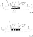
Figure 4 shows an example in which the payload is a neutrally buoyant external battery; and -
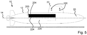
Figure 5 shows an example in which the payload is a neutrally buoyant external diesel tank. - The
watercraft system 10 is illustrated with reference toFigs. 1 to 5 . Thewatercraft system 10 of the present disclosure may comprises a submarine, for example a submersible configured to be submerged in water. Hence thewatercraft system 10 comprises a vessel with a water/air tightsealable hull 12, for example a pressure hull. Thehull 12 may have alongitudinal axis 14. Hence thehull 12 defines and/or surrounds a pressure vessel. Thewatercraft system 10 and/or thehull 12 may extend between anaft end 16 and aforward end 18. As illustrated in the figures, theaft end 16 may be spaced apart from theforward end 18 along thelongitudinal axis 14. - The
hull 12 defines a hullouter surface 20. As shown inFig. 1 , thesystem 10 further comprises a releasable mountingsystem 100 for carrying apayload unit watercraft system 10, shown inFigures 2 to 5 . The payload unit(s) 202, 204 are carried external to the hullouter surface 20. - The
payload unit payload unit - Neutral buoyancy occurs when an object's average density is equal to the density of the fluid in which it is immersed, resulting in the buoyant force balancing the force of gravity that would otherwise cause the object to sink or rise. An object that has neutral buoyancy will neither sink nor rise in the supporting fluid.
- The releasable mounting
system 100 may comprise one or more releasable mounting units. In one example, one releasable mountingsystem unit 100 is provided on thehull 12. In other examples two or more releasable mountingsystem unit 100 are provided on thehull 12.Figure 1 shows the starboard side of a submarine, withunits 100 of the releasable mounting system provided on the side of the main hull and abridge fin 22. The port side (which is hidden in the figures, as the figures show only the starboard side) is also provided with units of the releasable mounting system 100 (for example in the same locations on the main hull andbridge fin 22 as on the starboard side). - The releasable mounting
system 100 may be provided with units for carrying payload units at the aft casing deck, lateral sides of the hull and/or the keel. - The releasable mounting
system 100 is operable to release (e.g. uncouple), thepayload unit hull 12. - In one example, one
payload unit outer surface 20. In other examples two ormore payload units outer surface 20.Figures 2 to 5 show the starboard side of a submarine configured to carry apayload 204. The port side is also configured to carry apayload 202. - Hence, as shown in
Figures 2 to 5 , thepayload unit side payload unit 202. The location of this is indicated by a dotted line, where dotted lines from their respective reference numerals indicate the feature being indicated is on the port side of thehull 12. The releasable mountingsystem 100 may comprise aport side unit 110 located on the port side of thehull 12 for carrying and releasing the portside payload unit 202. Theport side unit 110 may comprise a port side payloadunit mounting apparatus 132. In the examples shown, six side units (e.g. pads) 110 are shown, each with a mountingapparatus 132. - The port side payload
unit mounting apparatus 132 may be operable to have a first configuration in which the port side payloadunit mounting apparatus 132 is engaged with (e.g. fixed to) the portside payload unit 202, and thus locate the portside payload unit 202 on the port side of thehull 12. - The port side payload
unit mounting apparatus 132 may be operable to have a second configuration in which the port side payloadunit mounting apparatus 132 is disengaged (e.g. uncoupled) from the portside payload unit 202, so that the portside payload unit 202 can be separated from thehull 12. - The port side payload
unit mounting apparatus 132 may comprise a mounting bolt. In the first configuration the mounting bolt carries the portside payload unit 202. In the second configuration the mounting bolt is removed (i.e. undone) to releases the portside payload unit 202 from thehull 12. - The port side payload
unit mounting apparatus 132 may comprise a port sideexplosive release unit 142. In the first configuration the port sideexplosive release unit 142 carries the portside payload unit 202. In the second configuration the port sideexplosive release unit 142 releases the portside payload unit 202 from thehull 12. - Additionally or alternatively, as shown in
Figures 2 to 5 , thepayload unit side payload unit 204. The releasable mountingsystem 100 may comprise astarboard side unit 120 located on the starboard side of thehull 12 for carrying and releasing a starboardside payload unit 204. Thestarboard side unit 120 may comprise a starboard side payloadunit mounting apparatus 134. - The starboard side payload
unit mounting apparatus 134 may be operable to have a first configuration in which the starboard side payloadunit mounting apparatus 134 is engaged with (e.g. fixed to) the starboardside payload unit 204, and thus locate the starboardside payload unit 204 on the starboard side of thehull 12. - The starboard side payload
unit mounting apparatus 134 may be operable to have a second configuration in which the starboard side payloadunit mounting apparatus 134 is disengaged (e.g. uncoupled) from the starboardside payload unit 204, so that the starboardside payload unit 204 can be separated from thehull 12. - The starboard side payload
unit mounting apparatus 134 may comprise a mounting bolt. In the first configuration the mounting bolt carries the starboardside payload unit 204. In the second configuration the mounting bolt is removed (i.e. undone) to release the starboardside payload unit 204 from thehull 12. - The starboard side payload
unit mounting apparatus 134 may comprise a starboard sideexplosive release unit 144. In the first configuration the starboard sideexplosive release unit 144 carries the starboardside payload unit 204. In the second configuration the starboard sideexplosive release unit 144 releases the starboardside payload unit 204 from thehull 12. - The port side payload
unit mounting apparatus 132 may be operable to switch from the first configuration to the second configuration in response to a first command signal, for example generated by a user or a control system. - The starboard side payload
unit mounting apparatus 134 may be operable to switch from the first configuration to the second configuration in response to a second command signal, for example generated by a user or a control system. - The first command signal and second command signal may be derived from a common command signal, for example generated by a user or a control system.
- The port side payload
unit mounting apparatus 132 and the starboard side payloadunit mounting apparatus 134 may be independently operable to switch from the first configuration to the second configuration. That is to say, the port side payloadunit mounting apparatus 132 may be operable to switch from the first configuration to the second configuration independently of the starboard side payloadunit mounting apparatus 134 switching from the first configuration to the second configuration, and/or the starboard side payloadunit mounting apparatus 134 may be operable to switch from the first configuration to the second configuration independently of the port side payloadunit mounting apparatus 132 switching from the first configuration to the second configuration. - The port side
explosive release unit 142 may comprise one or more explosive bolts (e.g. a pyrotechnic fastener). The starboard sideexplosive release unit 144 may comprise one or more explosive bolts (e.g. pyrotechnic fastener). - In examples in which a payload unit is mounted to a location other than the port or starboard side of the hull, it may be mounted and released using the same mount and release features and mechanisms as described with reference to the port and starboard mounted payload units.
- The (or each)
payload unit hull 12. The (or each)payload unit - In such examples, the
payload unit Figure 2 . Alternatively, in such examples, thepayload unit rechargeable battery system 206, a 'single shot'disposable battery system 206, as shown inFigure 4 . - The
payload unit payload unit payload unit payload unit payload unit payload unit - In such an example, the
payload unit fuel tank 210, projectile storage and/orlaunch system 208, sea-bed deployable system. - Hence a
payload unit - Examples of the
payload units - As set out above, the
payload unit payload unit payload unit - During operation, the
payload unit payload unit payload unit - The method of operation may comprise the step of controlling a flow of water into the
payload unit payload unit - In the example of
Fig 3 thepayload unit storage chambers 220 in which objects are stored until deployed. Thepayload unit floodable water tanks 222. When an object is removed from astorage chamber 220 in the payload unit, at least a proportion of one or more of therespective storage chamber 220 is flooded. If required, at least a proportion of one or more of the floodable water tanks 222 (which were empty/dry while the object was being stored) may also be flooded, so that the weight of water which has entered the payload unit is equal to the weight of the object which has left the payload unit. - In the example of
Figure 5 , thepayload unit fuel tank 224 and afloodable water tank 226. During operation, weight of water taken intotank 226 is controlled to equal to weight of fuel transferred fromtank 224. The control of this this may be via a flow meter on a fuel pipe and a proportional control valve combined with a flow meter on a water tank inlet such that weight of fuel (for example diesel) transferred from the tank is equal to weight of water transferred into the tank. - Hence there is provided a
watercraft system 10 comprising a submarine with releasable mountingsystem 100 operable to carry or release apayload unit hull 12 of the submarine. - The releasable mounting
system 100 is operable to uncouple thepayload unit hull 12 when required, and to carry the payload for as long as needed. In particular the releasable mounting system provides for ease of mounting and detaching of the payload from the submarine. - Since the
payload unit payload unit - This enables the capacity of volumetric size of the
watercraft system 10 to be adjusted. - This also enables equipment of the
watercraft system 10 to moved, removed, replaced, fitted as required. This has significant maintenance advantages since it means that equipment or material in thepayload unit watercraft system 10 so that it may be worked on more easily away from the submarine. This also means that asubstitute payload unit submarine hull 12 to get it operational as soon as possible rather than waiting for theformer payload unit - Hence a
watercraft system 10 may be quickly configured to meet the needs of a particular operational role or test by adapting thewatercraft system 10 fit the desired range of equipment. - The payload units may be re-used. For example, after a first use, the payload units may be renewed, refuelled, re-loaded etc, and attached to the same of a different submarine hull.
- The payload units may jettisoned during operation of the submarine (for example by triggering the explosive bolts) to reduce the amount of fuel used by the submarine and/or to increase its speed and manoeuvrability.
- Attention is directed to all papers and documents which are filed concurrently with or previous to this specification in connection with this application and which are open to public inspection with this specification, and the contents of all such papers and documents are incorporated herein by reference.
- All of the features disclosed in this specification (including any accompanying claims, abstract and drawings), and/or all of the steps of any method or process so disclosed, may be combined in any combination, except combinations where at least some of such features and/or steps are mutually exclusive.
- Each feature disclosed in this specification (including any accompanying claims, abstract and drawings) may be replaced by alternative features serving the same, equivalent or similar purpose, unless expressly stated otherwise. Thus, unless expressly stated otherwise, each feature disclosed is one example only of a generic series of equivalent or similar features.
- The invention is not restricted to the details of the foregoing embodiment(s). The invention extends to any novel one, or any novel combination, of the features disclosed in this specification (including any accompanying claims, abstract and drawings), or to any novel one, or any novel combination, of the steps of any method or process so disclosed.
Claims (15)
- A watercraft system, wherein the watercraft system comprises:a submarine or a submersible configured to be submerged in water, having an external hull having a longitudinal axis which extends between an aft end and a forward end, the hull defining a hull outer surface; a releasable mounting system for carrying a payload unit external to the hull outer surface; the releasable mounting system operable to release the payload unit from the hull;wherein the watercraft system further comprises a payload unit which is neutrally buoyant.
- A watercraft system as claimed in claim 1 wherein the payload unit is operable to remain neutrally buoyant while coupled to the hull.
- A watercraft system as claimed in claim 2 wherein the payload unit comprises at least one of:a sensor system;a sonar system;a rechargeable battery system;a 'single shot' disposable battery system;a watercraft signature altering system; ora sea-bed deployable system.
- A watercraft system as claimed in claim 2 wherein the payload unit is operable to carry a material which is removable from the payload unit during the operation of the payload unit; and
the payload unit is operable to receive a mass of water into the payload unit which equals the mass of material removed from the payload unit. - A watercraft system as claimed in claim 4 wherein the payload unit comprises at least one of:a fuel tank;projectile storage and/or launch system; ora sea-bed deployable system.
- A watercraft system as claimed in any one of claims 1 to 5 wherein the payload unit comprises a port side payload unit;
the releasable mounting system comprises:a port side unit located on the port side of the hull for carrying and releasing the port side payload unit; andthe port side unit comprises a port side payload unit mounting apparatus; andthe port side payload unit mounting apparatus is operable to have:a first configuration in which the port side payload unit mounting apparatus is engaged with the port side payload unit;a second configuration in which the port side payload unit mounting apparatus is disengaged from the port side payload unit. - A watercraft system as claimed in claim 6 wherein the the port side payload unit mounting apparatus is operable to switch from the first configuration to the second configuration in response to a first command signal.
- A watercraft system as claimed in any one of claims 1 to 7 wherein the payload unit comprises a starboard side payload unit;
the releasable mounting system comprises:a starboard side unit located on the starboard side of the hull for carrying and releasing a starboard side payload unit;the starboard side unit comprises a starboard side payload unit mounting apparatus;the starboard side payload unit mounting apparatus operable to have:a first configuration in which the starboard side payload unit mounting apparatus is engaged with the starboard side payload unit; anda second configuration in which the starboard side payload unit mounting apparatus is disengaged from the starboard side payload unit. - A watercraft system as claimed in claim 8 wherein the the starboard side payload unit mounting apparatus is operable to switch from the first configuration to the second configuration in response to a second command signal.
- A watercraft system as claimed in claim 9 when dependent on claim 7 wherein the first command signal and second command signal are derived from a common command signal.
- A watercraft system as claimed in claim 10, or as claimed in claim 9 when dependent on claim 7, wherein:
the port side payload unit mounting apparatus and the starboard side payload unit mounting apparatus are independently operable to switch from the first configuration to the second configuration. - A watercraft system as claimed in claim 6 or claim 7 wherein
the port side payload unit mounting apparatus comprises a port side explosive release unit, wherein:in the first configuration the port side explosive release unit carries the port side payload unit; andin the second configuration the port side explosive release unit releases the port side payload unit from the hull. - A watercraft system as claimed in claim 8 or claim 9 wherein
the starboard side payload unit mounting apparatus comprises a starboard side explosive release unit, wherein:in the first configuration the starboard side explosive release unit carries the starboard side payload unit; andin the second configuration the starboard side explosive release unit releases the starboard side payload unit from the hull . - A method of operation of a watercraft system, wherein the watercraft system comprises:a submarine or a submersible configured to be submerged in water, having an external hull having a longitudinal axis which extends between an aft end and a forward end, the hull defining a hull outer surface ; a releasable mounting system for carrying a payload unit external to the hull outer surface; the releasable mounting system operable to release the payload unit from the hull;wherein the watercraft system further comprises a payload unit;the method characterised by controlling the payload unit to be neutrally buoyant during operation of the payload unit.
- A method as claimed in claim 14 wherein the payload unit is operable to carry a material which is removed from the payload unit during the operation of the payload unit; and
the method comprises the step of controlling a flow of water into the payload unit so that the mass of water entering the payload unit equals the mass of material removed from the payload unit.
Priority Applications (5)
| Application Number | Priority Date | Filing Date | Title |
|---|---|---|---|
| EP21275070.7A EP4098546A1 (en) | 2021-06-02 | 2021-06-02 | Improved watercraft system |
| PCT/GB2022/051241 WO2022254176A1 (en) | 2021-06-02 | 2022-05-18 | Improved watercraft system |
| US18/563,613 US20240217636A1 (en) | 2021-06-02 | 2022-05-18 | Improved watercraft system |
| EP22725923.1A EP4347381B1 (en) | 2021-06-02 | 2022-05-18 | Improved watercraft system |
| AU2022286689A AU2022286689A1 (en) | 2021-06-02 | 2022-05-18 | Improved watercraft system |
Applications Claiming Priority (1)
| Application Number | Priority Date | Filing Date | Title |
|---|---|---|---|
| EP21275070.7A EP4098546A1 (en) | 2021-06-02 | 2021-06-02 | Improved watercraft system |
Publications (1)
| Publication Number | Publication Date |
|---|---|
| EP4098546A1 true EP4098546A1 (en) | 2022-12-07 |
Family
ID=76269681
Family Applications (1)
| Application Number | Title | Priority Date | Filing Date |
|---|---|---|---|
| EP21275070.7A Pending EP4098546A1 (en) | 2021-06-02 | 2021-06-02 | Improved watercraft system |
Country Status (1)
| Country | Link |
|---|---|
| EP (1) | EP4098546A1 (en) |
Citations (4)
| Publication number | Priority date | Publication date | Assignee | Title |
|---|---|---|---|---|
| US2332549A (en) * | 1941-07-15 | 1943-10-26 | Carl J Baer | Submarine craft |
| US4306413A (en) * | 1975-06-30 | 1981-12-22 | The United States Of America As Represented By The Secretary Of The Navy | Hydraulic power and control system |
| DE102004060010B3 (en) * | 2004-12-14 | 2005-12-22 | Atlas Elektronik Gmbh | Unmanned underwater vehicle, has density and volume of buoyancy unit selected to compensate for gravitational force |
| WO2016087090A1 (en) * | 2014-12-05 | 2016-06-09 | Thyssenkrupp Marine Systems Gmbh | Underwater rapid unloading system |
-
2021
- 2021-06-02 EP EP21275070.7A patent/EP4098546A1/en active Pending
Patent Citations (4)
| Publication number | Priority date | Publication date | Assignee | Title |
|---|---|---|---|---|
| US2332549A (en) * | 1941-07-15 | 1943-10-26 | Carl J Baer | Submarine craft |
| US4306413A (en) * | 1975-06-30 | 1981-12-22 | The United States Of America As Represented By The Secretary Of The Navy | Hydraulic power and control system |
| DE102004060010B3 (en) * | 2004-12-14 | 2005-12-22 | Atlas Elektronik Gmbh | Unmanned underwater vehicle, has density and volume of buoyancy unit selected to compensate for gravitational force |
| WO2016087090A1 (en) * | 2014-12-05 | 2016-06-09 | Thyssenkrupp Marine Systems Gmbh | Underwater rapid unloading system |
Similar Documents
| Publication | Publication Date | Title |
|---|---|---|
| AU2015218823B2 (en) | Autonomous underwater vehicle with external, deployable payload | |
| RU2681415C1 (en) | Compact multi-functional autonomous uninhabited underwater vehicle -carrier vehicle for replaceable actual load | |
| US9611017B2 (en) | Multiple torpedo storage and launch system | |
| US5979354A (en) | Submarine | |
| US8833288B2 (en) | Unmanned underwater vehicle and method for recovering such vehicle | |
| CA2730100A1 (en) | General purpose submarine having high speed surface capability | |
| US20110226173A1 (en) | Fleet protection attack craft | |
| US9291438B2 (en) | Catamaran surface vessel with removable mission-specific payload module | |
| US6376762B1 (en) | Small vehicle launch platform | |
| US3368510A (en) | Minelaying submarine | |
| US20240217636A1 (en) | Improved watercraft system | |
| JP6639893B2 (en) | Multiple torpedo containment and launch systems | |
| GB2607314A (en) | Improved watercraft system | |
| US6158370A (en) | Submersible underwater vehicle ballast equalization system | |
| KR20230092655A (en) | Unmanned submersible vehicle with horizontal and vertical attitude change launch system | |
| US4449472A (en) | Detachable storage tank for hydrofoils | |
| EP2776311B1 (en) | Dry shelter for increasing the operational capability of a submarine | |
| US7159501B1 (en) | Stackable in-line surface missile launch system for a modular payload bay | |
| RU2859131C1 (en) | Underwater towing vehicle | |
| RU2798921C1 (en) | Fast rescue vessel | |
| RU238438U1 (en) | Unmanned Controlled Boat | |
| RU2851269C2 (en) | Autonomous unmanned underwater vehicle for rescue of submariners | |
| RU204780U1 (en) | Double-hull rescue underwater vehicle | |
| RU2319636C2 (en) | Submersible boat | |
| Gabler | Submarine Construction (Unterseebootsbau) |
Legal Events
| Date | Code | Title | Description |
|---|---|---|---|
| PUAI | Public reference made under article 153(3) epc to a published international application that has entered the european phase |
Free format text: ORIGINAL CODE: 0009012 |
|
| STAA | Information on the status of an ep patent application or granted ep patent |
Free format text: STATUS: THE APPLICATION HAS BEEN PUBLISHED |
|
| AK | Designated contracting states |
Kind code of ref document: A1 Designated state(s): AL AT BE BG CH CY CZ DE DK EE ES FI FR GB GR HR HU IE IS IT LI LT LU LV MC MK MT NL NO PL PT RO RS SE SI SK SM TR |