EP4098458A1 - Wheel and scooter - Google Patents
Wheel and scooter Download PDFInfo
- Publication number
- EP4098458A1 EP4098458A1 EP21206844.9A EP21206844A EP4098458A1 EP 4098458 A1 EP4098458 A1 EP 4098458A1 EP 21206844 A EP21206844 A EP 21206844A EP 4098458 A1 EP4098458 A1 EP 4098458A1
- Authority
- EP
- European Patent Office
- Prior art keywords
- wheel
- bearing
- fitted
- support
- hub
- Prior art date
- Legal status (The legal status is an assumption and is not a legal conclusion. Google has not performed a legal analysis and makes no representation as to the accuracy of the status listed.)
- Granted
Links
Images
Classifications
-
- B—PERFORMING OPERATIONS; TRANSPORTING
- B60—VEHICLES IN GENERAL
- B60B—VEHICLE WHEELS; CASTORS; AXLES FOR WHEELS OR CASTORS; INCREASING WHEEL ADHESION
- B60B27/00—Hubs
-
- B—PERFORMING OPERATIONS; TRANSPORTING
- B60—VEHICLES IN GENERAL
- B60B—VEHICLE WHEELS; CASTORS; AXLES FOR WHEELS OR CASTORS; INCREASING WHEEL ADHESION
- B60B27/00—Hubs
- B60B27/0078—Hubs characterised by the fixation of bearings
-
- B—PERFORMING OPERATIONS; TRANSPORTING
- B60—VEHICLES IN GENERAL
- B60B—VEHICLE WHEELS; CASTORS; AXLES FOR WHEELS OR CASTORS; INCREASING WHEEL ADHESION
- B60B3/00—Disc wheels, i.e. wheels with load-supporting disc body
- B60B3/001—Lightweight wheels, e.g. for strollers or toys
-
- A—HUMAN NECESSITIES
- A63—SPORTS; GAMES; AMUSEMENTS
- A63C—SKATES; SKIS; ROLLER SKATES; DESIGN OR LAYOUT OF COURTS, RINKS OR THE LIKE
- A63C17/00—Roller skates; Skate-boards
- A63C17/01—Skateboards
-
- B—PERFORMING OPERATIONS; TRANSPORTING
- B60—VEHICLES IN GENERAL
- B60B—VEHICLE WHEELS; CASTORS; AXLES FOR WHEELS OR CASTORS; INCREASING WHEEL ADHESION
- B60B19/00—Wheels not otherwise provided for or having characteristics specified in one of the subgroups of this group
-
- B—PERFORMING OPERATIONS; TRANSPORTING
- B60—VEHICLES IN GENERAL
- B60B—VEHICLE WHEELS; CASTORS; AXLES FOR WHEELS OR CASTORS; INCREASING WHEEL ADHESION
- B60B27/00—Hubs
- B60B27/02—Hubs adapted to be rotatably arranged on axle
- B60B27/023—Hubs adapted to be rotatably arranged on axle specially adapted for bicycles
-
- B—PERFORMING OPERATIONS; TRANSPORTING
- B60—VEHICLES IN GENERAL
- B60B—VEHICLE WHEELS; CASTORS; AXLES FOR WHEELS OR CASTORS; INCREASING WHEEL ADHESION
- B60B3/00—Disc wheels, i.e. wheels with load-supporting disc body
- B60B3/04—Disc wheels, i.e. wheels with load-supporting disc body with a single disc body not integral with rim, i.e. disc body and rim being manufactured independently and then permanently attached to each other in a second step, e.g. by welding
- B60B3/048—Disc wheels, i.e. wheels with load-supporting disc body with a single disc body not integral with rim, i.e. disc body and rim being manufactured independently and then permanently attached to each other in a second step, e.g. by welding the rim being rotatably mounted to the wheel disc
-
- B—PERFORMING OPERATIONS; TRANSPORTING
- B62—LAND VEHICLES FOR TRAVELLING OTHERWISE THAN ON RAILS
- B62K—CYCLES; CYCLE FRAMES; CYCLE STEERING DEVICES; RIDER-OPERATED TERMINAL CONTROLS SPECIALLY ADAPTED FOR CYCLES; CYCLE AXLE SUSPENSIONS; CYCLE SIDECARS, FORECARS, OR THE LIKE
- B62K19/00—Cycle frames
- B62K19/30—Frame parts shaped to receive other cycle parts or accessories
-
- B—PERFORMING OPERATIONS; TRANSPORTING
- B62—LAND VEHICLES FOR TRAVELLING OTHERWISE THAN ON RAILS
- B62K—CYCLES; CYCLE FRAMES; CYCLE STEERING DEVICES; RIDER-OPERATED TERMINAL CONTROLS SPECIALLY ADAPTED FOR CYCLES; CYCLE AXLE SUSPENSIONS; CYCLE SIDECARS, FORECARS, OR THE LIKE
- B62K3/00—Bicycles
- B62K3/002—Bicycles without a seat, i.e. the rider operating the vehicle in a standing position, e.g. non-motorized scooters; non-motorized scooters with skis or runners
-
- B—PERFORMING OPERATIONS; TRANSPORTING
- B62—LAND VEHICLES FOR TRAVELLING OTHERWISE THAN ON RAILS
- B62K—CYCLES; CYCLE FRAMES; CYCLE STEERING DEVICES; RIDER-OPERATED TERMINAL CONTROLS SPECIALLY ADAPTED FOR CYCLES; CYCLE AXLE SUSPENSIONS; CYCLE SIDECARS, FORECARS, OR THE LIKE
- B62K3/00—Bicycles
- B62K3/02—Frames
-
- F—MECHANICAL ENGINEERING; LIGHTING; HEATING; WEAPONS; BLASTING
- F16—ENGINEERING ELEMENTS AND UNITS; GENERAL MEASURES FOR PRODUCING AND MAINTAINING EFFECTIVE FUNCTIONING OF MACHINES OR INSTALLATIONS; THERMAL INSULATION IN GENERAL
- F16C—SHAFTS; FLEXIBLE SHAFTS; ELEMENTS OR CRANKSHAFT MECHANISMS; ROTARY BODIES OTHER THAN GEARING ELEMENTS; BEARINGS
- F16C33/00—Parts of bearings; Special methods for making bearings or parts thereof
- F16C33/30—Parts of ball or roller bearings
- F16C33/58—Raceways; Race rings
- F16C33/583—Details of specific parts of races
-
- F—MECHANICAL ENGINEERING; LIGHTING; HEATING; WEAPONS; BLASTING
- F16—ENGINEERING ELEMENTS AND UNITS; GENERAL MEASURES FOR PRODUCING AND MAINTAINING EFFECTIVE FUNCTIONING OF MACHINES OR INSTALLATIONS; THERMAL INSULATION IN GENERAL
- F16C—SHAFTS; FLEXIBLE SHAFTS; ELEMENTS OR CRANKSHAFT MECHANISMS; ROTARY BODIES OTHER THAN GEARING ELEMENTS; BEARINGS
- F16C33/00—Parts of bearings; Special methods for making bearings or parts thereof
- F16C33/72—Sealings
- F16C33/76—Sealings of ball or roller bearings
- F16C33/78—Sealings of ball or roller bearings with a diaphragm, disc, or ring, with or without resilient members
- F16C33/7816—Details of the sealing or parts thereof, e.g. geometry, material
- F16C33/782—Details of the sealing or parts thereof, e.g. geometry, material of the sealing region
-
- B—PERFORMING OPERATIONS; TRANSPORTING
- B60—VEHICLES IN GENERAL
- B60B—VEHICLE WHEELS; CASTORS; AXLES FOR WHEELS OR CASTORS; INCREASING WHEEL ADHESION
- B60B2200/00—Type of product being used or applied
- B60B2200/40—Articles of daily use
- B60B2200/47—Physical activity equipment, e.g. leisure or sports articles
-
- F—MECHANICAL ENGINEERING; LIGHTING; HEATING; WEAPONS; BLASTING
- F16—ENGINEERING ELEMENTS AND UNITS; GENERAL MEASURES FOR PRODUCING AND MAINTAINING EFFECTIVE FUNCTIONING OF MACHINES OR INSTALLATIONS; THERMAL INSULATION IN GENERAL
- F16C—SHAFTS; FLEXIBLE SHAFTS; ELEMENTS OR CRANKSHAFT MECHANISMS; ROTARY BODIES OTHER THAN GEARING ELEMENTS; BEARINGS
- F16C2326/00—Articles relating to transporting
- F16C2326/01—Parts of vehicles in general
- F16C2326/02—Wheel hubs or castors
Definitions
- the present disclosure relates to a field of wheels, and more particularly, to a wheel and a scooter.
- a wheel structure of a scooter, a balance bike, a bicycle or other vehicles is designed in various forms, so as to improve the aesthetics and the user experience.
- the wheel structure usually includes a tire, a hub, a spoke, and a central shaft, and various forms of spokes are connected to the hub, so as to obtain an expected appearance effect.
- the wheel in the related prior art has the problems of a complex structure and a lack of sense of science and technology.
- the present disclosure provides a wheel and a scooter, so as to simplify the structure arrangement of the wheel and improve the appearance effect and the sense of science and technology of the wheel and the scooter.
- a wheel for a scooter which is adapted to be assembled and fitted with a frame of the scooter.
- the wheel includes a bearing support, a hub and at least one bearing.
- the bearing support includes an inner surface facing towards a rotation center of the wheel.
- the inner surface defines a hollow area surrounded by the inner surface.
- Each bearing includes an outer ring and an inner ring, the outer ring is fixedly connected to the hub, and the inner ring and the frame are fixedly connected to the bearing support, respectively.
- the bearing support includes a supporting body and a connecting structure connected to the supporting body, the bearing is fitted with the supporting body, and the frame is fitted with the connecting structure.
- At least a part of the connecting structure protrudes beyond the hub.
- the bearing support includes two connecting structures arranged on two opposite sides of the supporting body respectively.
- a width of the supporting body in an axial direction of the wheel matches with a width of the hub in the axial direction of the wheel.
- the bearing support includes at least two support bodies, and the at least two support bodies are assembled and fitted with each other.
- the wheel includes at least two bearings
- the bearing support includes a left edge and a right edge arranged along an axial direction of the wheel, the inner ring of at least one of the at least two bearings is fitted with the left edge, and the inner ring of at least one bearing is fitted with the right edge.
- the wheel further includes at least one bearing end cover, the bearing end cover is fixedly connected to the hub, and the bearing end cover is hermetically fitted with a side surface of the bearing.
- the wheel further includes a sealing member arranged between the bearing end cover and the bearing, and the sealing member is hermetically fitted with the bearing end cover and the side surface of the bearing.
- a section of the hollow area perpendicular to an axial direction of the wheel has a circle shape or a rectangle shape.
- a scooter is provided.
- the scooter includes a main body, a frame connected to the main body and the wheel according to the first aspect of the present disclosure, and the bearing support is fixedly connected to the frame.
- the wheel of the present disclosure includes the bearing support, the bearing and the hub, and the outer ring of the bearing is fixedly connected to the hub, so that the hub can rotate relative to the frame based on a fixed connection between the bearing support and the frame.
- the inner ring of the bearing is fixedly connected to the bearing support, so as to realize a support function for the bearing and other structures around the bearing through the bearing support. Since the wheel further includes a hollow area surrounded by the inner surface of the bearing support, the wheel obtains a hollow appearance effect, thus simplifying the wheel structure, and improving the appearance effect and the sense of science and technology of the wheel and the scooter using the above wheel.
- the present disclosure provides a wheel which is adapted to be assembled and fitted with a frame, and the wheel includes a bearing support, a hub and at least one bearing.
- the bearing includes an outer ring and an inner ring, the outer ring is fixedly connected to the hub, and the inner ring and the frame are fixedly connected to the bearing support, respectively.
- the bearing support includes an inner surface facing towards a rotation center of the wheel, and the inner surface defines a hollow area surrounded by the inner surface.
- the hub can rotate relative to the frame based on a fixed connection between the bearing support and the frame.
- the inner ring of the bearing is fixedly connected to the bearing support, to realize a support function for the bearing and other structures around the bearing through the bearing support.
- the wheel further includes the hollow area surrounded by the inner surface of the bearing support, the wheel obtains a hollow appearance effect, thus simplifying the wheel structure, and improving the appearance effect and the sense of science and technology of the wheel. Since the wheel structure is simplified, the material used for the wheel and the cost of the wheel are reduced, and the carbon emission is reduced.
- one, two or more bearings may be provided, which is not limited by the present disclosure.
- the wheel structure is exemplarily described below by taking an example in which the wheel includes two bearings.
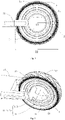
- Fig. 1 is a side view of the wheel and the frame fitted with each other in an exemplary embodiment of the present disclosure.
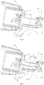
- Fig. 2 is a perspective view of the wheel and the frame fitted with each other in an exemplary embodiment of the present disclosure.
- Fig. 3 is a sectional view of the wheel and the frame fitted with each other in an exemplary embodiment of the present disclosure.
- a dash dotted line in Fig. 2 and Fig. 3 represents a rotation center axis of a wheel 1.
- the wheel 1 is assembled and fitted with the frame 21.
- the wheel 1 includes a bearing support 11, a hub 12 and two bearings 13.
- Each bearing 13 includes an outer ring 131 and an inner ring 132, the outer ring 131 is fixedly connected to the hub 12, and the inner ring 132 and the frame 21 are fixedly connected to the bearing support 11, respectively.
- the bearing support 11 includes an inner surface 1111 facing towards a rotation center of the wheel 1, and the inner surface 1111 defines a hollow area 14 surrounded by the inner surface 1111.
- a section of the hollow area 14 perpendicular to an axial direction of the wheel 1 has a circle shape, a polygon shape or other irregular shapes, which is not limited by the present disclosure.
- the section of the hollow area 14 perpendicular to the axial direction of the wheel 1 has the circle shape, the overall aesthetics and the sense of science and technology of the wheel 1 can be improved.
- a characteristic dimension D1 of the hollow area can be greater than or equal to one-third of a contour diameter D2 of the wheel 1, and less than or equal to two-thirds of the contour diameter D2 of the wheel 1, so as to obtain a great appearance effect of a hollow wheel without affecting a structural arrangement of the wheel 1.
- the contour diameter D2 of the wheel 1 may also be another multiple of the characteristic dimension D1 of the hollow area, which is not limited by the present disclosure.
- the characteristic dimension D1 of the hollow area can refer to a characteristic dimension that can reflect an overall shape of the hollow area.
- the characteristic dimension D1 of the hollow area can be a diameter of the circle.
- the characteristic dimension D1 of the hollow area can be a diagonal length of the rectangle.
- the bearing support 11 is fixedly connected to the frame 21, and the outer rings 131 of the two bearings 13 are fixedly connected to the hub 12, respectively, the hub 12 can rotate relative to the frame 21.
- the inner rings 132 of the two bearings 13 are fixedly connected to the bearing support 11, respectively, so as to support the bearing 13 and other structures around the bearing 13 through the bearing support 11, thus ensuring the overall structural strength of the wheel 1.
- the wheel 1 further includes the hollow area 14 surrounded by the inner surface 1111 of the bearing support 11, the wheel 1 obtains a hollow appearance effect, thus simplifying the structure of the wheel 1, and improving the appearance effect and the sense of science and technology of the wheel 1.
- the inner ring 132 of the bearing 13 can be fitted over the bearing support 11, and a fixed connection can be realized by interference fit, clamping, threaded connection, welding, etc.
- the hub 12 can be fitted over the outer ring 131 of the bearing 13, and a fixed connection can be realized by interference fit, clamping, threaded connection, welding, etc.
- the bearing support 11 may be a structural member formed by one support body 113, or the bearing support 11 may also be a structural assembly formed by two or more support bodies 113 assembled and fitted with each other, which is not limited by the present disclosure.
- the bearing support 11 may include a supporting body 111 and a connecting structure 112 connected to the supporting body 111, the bearing 13 is fitted with the supporting body 111, and the frame 21 is fitted with the connecting structure 112.
- a support function for the structure of the wheel 1 is realized through the fit of the supporting body 111 and the bearing 13, and a fixed connection with the frame 21 is realized through the connecting structure 112, thus avoiding the structural and functional interferences between the supporting body 111 and the connecting structure 112 during assembling and use, and improving the reliability of the wheel 1.
- the bearing support 11 may include two connecting structures 112 arranged on two opposite sides of the supporting body 111, respectively, so as to assemble the wheel 1 with the frame 21 through the fixed connection between the connecting structures 112 located on the two sides of the supporting body 111 and the frame 21, thus improving the stability of the use of the wheel 1.
- the bearing support 11 is the structural assembly formed by two or more support bodies 113 assembled and fitted with each other, as shown in Fig. 4 , the two or more support bodies 113 are assembled and fitted to form the bearing support 11. Partial structures of the two or more support bodies 113 are assembled to form the supporting body 111, and at least one support body 113 includes the connecting structure 112.
- the bearing support 11 includes two support bodies 113 and two bearings 13.
- a width of the supporting body 111 in a axial direction of the wheel 1 can match with a width of the hub 12 in the axial direction of the wheel 1
- the inner surface 1111 of the bearing support 11 can refer to an inner surface of the supporting body 111
- the hollow area 14 of the wheel 1 can be surrounded by the inner surface of the supporting body 111, so that a width of the hollow area 14 in the axial direction of the wheel 1 matches with the width of the hub 12 in the axial direction of the wheel 1, thus improving the overall aesthetics of the wheel 1.
- At least a part of the connecting structure 112 protrudes beyond the hub 12 in the axial direction of the wheel 1, so as to facilitate the assembling and fitting of the frame 21 and the connecting structure 112 and also to avoid the structural interference between the frame 21 and the wheel 1.
- the supporting body 111 and the connecting structure 112 can be integrally formed, and the connecting structure 112 can also be assembled to the supporting body 111 by means of threaded connection, clamping, welding, etc.
- the present disclosure is not limited to this.
- the dash dotted line in these figures represents the rotation center axis of the wheel 1.
- the wheel 1 may include at least two bearings 13, the bearing support 11 includes a left edge and a right edge arranged along the axial direction of the wheel 1, the inner ring 132 of at least one of the at least two bearings 13 is fitted with the left edge, and the inner ring 132 of at least another one of the at least two bearings 13 is fitted with the right edge, so as to improve the rotation stability of the wheel 1 by increasing a number of the bearings 13 and optimizing distribution positions of the bearings 13.
- the wheel 1 may also include one bearing 13 which matches with a width of the bearing support 11 in the axial direction of the wheel 1, thus simplifying the structure and the cost of the wheel 1.
- the wheel 1 may include one or more bearings 13, and the bearing support 11 may include one or more support bodies 113, which is not limited by the present disclosure. In some embodiments, when the bearing support 11 includes one support body 113, the wheel 1 may include one or more bearings 13. In other embodiments, when the bearing support 11 includes a plurality of support bodies 113, the wheel 1 may include one or more bearings 13.
- a number of the bearings 13 of the wheel 1 can match with a number of the support bodies 113 of the bearing support 11, and the bearings 13 can be correspondingly fitted with the support bodies 113 one to one, so as to adjust and calibrate the positions of the bearings 13 when assembling a plurality of support bodies 113, thus improving the mounting accuracy of the bearings 13.
- the wheel 1 further includes at least one bearing end cover 15.
- the bearing end cover 15 is fixedly connected to the hub 12, and hermetically fitted with a side surface of the bearing 13.
- the bearing end cover 15 can be fitted with the hub 12 to limit and seal the bearing 13, thus improving the dust-proof effect and the water-proof effect of the bearing 13.
- the wheel 1 includes two bearings 13 and one bearing end cover 15. A side surface of one bearing 13 of the two bearings 13 can be limited and sealed through the structure of the hub 12, and a side surface of the other bearing 13 of the two bearings 13 can be limited and sealed through the bearing end cover 15, so as to simplify the assembling of the wheel 1 and improve the dust-proof effect and the water-proof effect of the bearing 13.
- the wheel 1 may further include a sealing member 16 arranged between the bearing end cover 15 and the bearing 13, and the sealing member 16 is hermetically fitted with the bearing end cover 15 and the side surface of the bearing 13. Since the sealing member 16 seals between the bearing end cover 15 and the bearing 13, the sealing effect on the side surface of the bearing 13 is improved.
- the wheel 1 further includes a tire 17 assembled to an external side of the hub 12, so that the wheel 1 obtains a damping effect.
- the fixed connection between the bearing support 11 and the frame 21, between two adjacent support bodies 113, and between the bearing end cover 15 and the hub 12 can be realized by threaded connection, clamping, welding, etc., which is not limited by the present disclosure.
- the present disclosure further provided a scooter including a main body, a frame 21 connected to the main body, and the above wheel 1, and the bearing support 11 is fixedly connected to the frame 21.
- the wheel 1 includes the bearing support 11, the bearing 13 and the hub 12, and the outer ring 131 of the bearing 13 is fixedly connected to the hub 12, so that the hub 12 can rotate relative to the frame 21 based on the fixed connection between the bearing support 11 and the frame 21.
- the inner ring 132 of the bearing 13 is fixedly connected to the bearing support 11, so as to realize the support function for the bearing 13 and other structures around the bearing 13 through the bearing support 11. Since the wheel 1 further includes the hollow area 14 surrounded by the inner surface 1111 of the bearing support 11, the wheel 1 obtains the hollow appearance effect, simplifying the structure of the wheel 1, and improving the appearance effect and the sense of science and technology of the wheel 1 and the scooter using the above wheel 1.
Landscapes
- Engineering & Computer Science (AREA)
- Mechanical Engineering (AREA)
- General Engineering & Computer Science (AREA)
- Mounting Of Bearings Or Others (AREA)
- Automatic Cycles, And Cycles In General (AREA)
- Motorcycle And Bicycle Frame (AREA)
Abstract
Description
- The present disclosure relates to a field of wheels, and more particularly, to a wheel and a scooter.
- A wheel structure of a scooter, a balance bike, a bicycle or other vehicles is designed in various forms, so as to improve the aesthetics and the user experience. In the related art, the wheel structure usually includes a tire, a hub, a spoke, and a central shaft, and various forms of spokes are connected to the hub, so as to obtain an expected appearance effect. However, due to the limitation of the spoke and other basic structures, the wheel in the related prior art has the problems of a complex structure and a lack of sense of science and technology.
- The present disclosure provides a wheel and a scooter, so as to simplify the structure arrangement of the wheel and improve the appearance effect and the sense of science and technology of the wheel and the scooter.
- According to a first aspect of the present disclosure, a wheel for a scooter is provided, which is adapted to be assembled and fitted with a frame of the scooter. The wheel includes a bearing support, a hub and at least one bearing. The bearing support includes an inner surface facing towards a rotation center of the wheel. The inner surface defines a hollow area surrounded by the inner surface. Each bearing includes an outer ring and an inner ring, the outer ring is fixedly connected to the hub, and the inner ring and the frame are fixedly connected to the bearing support, respectively.
- Optionally, the bearing support includes a supporting body and a connecting structure connected to the supporting body, the bearing is fitted with the supporting body, and the frame is fitted with the connecting structure.
- Optionally, at least a part of the connecting structure protrudes beyond the hub.
- Optionally, the bearing support includes two connecting structures arranged on two opposite sides of the supporting body respectively.
- Optionally, a width of the supporting body in an axial direction of the wheel matches with a width of the hub in the axial direction of the wheel.
- Optionally, the bearing support includes at least two support bodies, and the at least two support bodies are assembled and fitted with each other.
- Optionally, the wheel includes at least two bearings, and the bearing support includes a left edge and a right edge arranged along an axial direction of the wheel, the inner ring of at least one of the at least two bearings is fitted with the left edge, and the inner ring of at least one bearing is fitted with the right edge.
- Optionally, the wheel further includes at least one bearing end cover, the bearing end cover is fixedly connected to the hub, and the bearing end cover is hermetically fitted with a side surface of the bearing.
- Optionally, the wheel further includes a sealing member arranged between the bearing end cover and the bearing, and the sealing member is hermetically fitted with the bearing end cover and the side surface of the bearing.
- Optionally, a section of the hollow area perpendicular to an axial direction of the wheel has a circle shape or a rectangle shape.
- According to a second aspect of the present disclosure, a scooter is provided. The scooter includes a main body, a frame connected to the main body and the wheel according to the first aspect of the present disclosure, and the bearing support is fixedly connected to the frame.
- Technical solutions provided by the embodiments of the present disclosure include the following beneficial effects.
- The wheel of the present disclosure includes the bearing support, the bearing and the hub, and the outer ring of the bearing is fixedly connected to the hub, so that the hub can rotate relative to the frame based on a fixed connection between the bearing support and the frame. The inner ring of the bearing is fixedly connected to the bearing support, so as to realize a support function for the bearing and other structures around the bearing through the bearing support. Since the wheel further includes a hollow area surrounded by the inner surface of the bearing support, the wheel obtains a hollow appearance effect, thus simplifying the wheel structure, and improving the appearance effect and the sense of science and technology of the wheel and the scooter using the above wheel.
- It should be understood that the above general description and the following detailed description are only exemplary and explanatory, and do not limit the present disclosure.
- The accompanying drawings incorporated into the specification and forming part of the specification, illustrate embodiments in accordance with the present disclosure, and are used with the specification to explain the principles of the present disclosure.
-
Fig. 1 is a side view of a wheel and a frame fitted with each other according to an exemplary embodiment of the present disclosure. -
Fig. 2 is a perspective view of a wheel and a frame fitted with each other according to an exemplary embodiment of the present disclosure. -
Fig. 3 is a sectional view of a wheel and a frame fitted with each other according to an exemplary embodiment of the present disclosure. -
Fig. 4 is a sectional view of a wheel and a frame fitted with each other according to another exemplary embodiment of the present disclosure. - Exemplary embodiments will be described in detail, and examples of the embodiments will be shown in the accompanying drawings. When the following description relates to the accompanying drawings, the same numbers in different accompanying drawings represent the same or similar elements unless otherwise indicated. The implementations described in the following exemplary embodiments do not represent all implementations consistent with the present disclosure. Instead, they are only examples of devices and methods consistent with some aspects of the present disclosure as detailed in the appended claims.
- The present disclosure provides a wheel which is adapted to be assembled and fitted with a frame, and the wheel includes a bearing support, a hub and at least one bearing. The bearing includes an outer ring and an inner ring, the outer ring is fixedly connected to the hub, and the inner ring and the frame are fixedly connected to the bearing support, respectively. The bearing support includes an inner surface facing towards a rotation center of the wheel, and the inner surface defines a hollow area surrounded by the inner surface.
- Since the wheel includes the bearing support, the bearing and the hub, and the outer ring of the bearing is fixedly connected to the hub, the hub can rotate relative to the frame based on a fixed connection between the bearing support and the frame. The inner ring of the bearing is fixedly connected to the bearing support, to realize a support function for the bearing and other structures around the bearing through the bearing support. Since the wheel further includes the hollow area surrounded by the inner surface of the bearing support, the wheel obtains a hollow appearance effect, thus simplifying the wheel structure, and improving the appearance effect and the sense of science and technology of the wheel. Since the wheel structure is simplified, the material used for the wheel and the cost of the wheel are reduced, and the carbon emission is reduced.
- According to the present disclosure, one, two or more bearings may be provided, which is not limited by the present disclosure. The wheel structure is exemplarily described below by taking an example in which the wheel includes two bearings.
-
Fig. 1 is a side view of the wheel and the frame fitted with each other in an exemplary embodiment of the present disclosure.Fig. 2 is a perspective view of the wheel and the frame fitted with each other in an exemplary embodiment of the present disclosure.Fig. 3 is a sectional view of the wheel and the frame fitted with each other in an exemplary embodiment of the present disclosure. As shown inFig. 1, Fig. 2 andFig. 3 , a dash dotted line inFig. 2 andFig. 3 represents a rotation center axis of awheel 1. Thewheel 1 is assembled and fitted with theframe 21. Thewheel 1 includes abearing support 11, ahub 12 and twobearings 13. Eachbearing 13 includes anouter ring 131 and aninner ring 132, theouter ring 131 is fixedly connected to thehub 12, and theinner ring 132 and theframe 21 are fixedly connected to thebearing support 11, respectively. Thebearing support 11 includes aninner surface 1111 facing towards a rotation center of thewheel 1, and theinner surface 1111 defines ahollow area 14 surrounded by theinner surface 1111. - In some embodiments, a section of the
hollow area 14 perpendicular to an axial direction of thewheel 1 has a circle shape, a polygon shape or other irregular shapes, which is not limited by the present disclosure. When the section of thehollow area 14 perpendicular to the axial direction of thewheel 1 has the circle shape, the overall aesthetics and the sense of science and technology of thewheel 1 can be improved. As shown inFig. 1 , a characteristic dimension D1 of the hollow area can be greater than or equal to one-third of a contour diameter D2 of thewheel 1, and less than or equal to two-thirds of the contour diameter D2 of thewheel 1, so as to obtain a great appearance effect of a hollow wheel without affecting a structural arrangement of thewheel 1. Or, the contour diameter D2 of thewheel 1 may also be another multiple of the characteristic dimension D1 of the hollow area, which is not limited by the present disclosure. - The characteristic dimension D1 of the hollow area can refer to a characteristic dimension that can reflect an overall shape of the hollow area. For example, when the hollow area has the circle shape, the characteristic dimension D1 of the hollow area can be a diameter of the circle. When the hollow area has the rectangle shape, the characteristic dimension D1 of the hollow area can be a diagonal length of the rectangle.
- Since two
bearings 13 are provided for thewheel 1, the overall structural strength and the rotation stability of thewheel 1 are improved. Since the bearingsupport 11 is fixedly connected to theframe 21, and theouter rings 131 of the twobearings 13 are fixedly connected to thehub 12, respectively, thehub 12 can rotate relative to theframe 21. Theinner rings 132 of the twobearings 13 are fixedly connected to thebearing support 11, respectively, so as to support thebearing 13 and other structures around the bearing 13 through the bearingsupport 11, thus ensuring the overall structural strength of thewheel 1. Since thewheel 1 further includes thehollow area 14 surrounded by theinner surface 1111 of the bearingsupport 11, thewheel 1 obtains a hollow appearance effect, thus simplifying the structure of thewheel 1, and improving the appearance effect and the sense of science and technology of thewheel 1. - It should be noted that the
inner ring 132 of thebearing 13 can be fitted over the bearingsupport 11, and a fixed connection can be realized by interference fit, clamping, threaded connection, welding, etc. Thehub 12 can be fitted over theouter ring 131 of thebearing 13, and a fixed connection can be realized by interference fit, clamping, threaded connection, welding, etc. - In some embodiments, the bearing
support 11 may be a structural member formed by onesupport body 113, or the bearingsupport 11 may also be a structural assembly formed by two ormore support bodies 113 assembled and fitted with each other, which is not limited by the present disclosure. - When the bearing
support 11 includes onesupport body 113, as shown inFig. 2 andFig. 3 , the bearingsupport 11 may include a supportingbody 111 and a connectingstructure 112 connected to the supportingbody 111, thebearing 13 is fitted with the supportingbody 111, and theframe 21 is fitted with the connectingstructure 112. A support function for the structure of thewheel 1 is realized through the fit of the supportingbody 111 and thebearing 13, and a fixed connection with theframe 21 is realized through the connectingstructure 112, thus avoiding the structural and functional interferences between the supportingbody 111 and the connectingstructure 112 during assembling and use, and improving the reliability of thewheel 1. - One, two or more connecting
structures 112 may be provided, which is not limited by the present disclosure. In some embodiments, as shown inFig. 2 andFig. 3 , the bearingsupport 11 may include two connectingstructures 112 arranged on two opposite sides of the supportingbody 111, respectively, so as to assemble thewheel 1 with theframe 21 through the fixed connection between the connectingstructures 112 located on the two sides of the supportingbody 111 and theframe 21, thus improving the stability of the use of thewheel 1. - When the bearing
support 11 is the structural assembly formed by two ormore support bodies 113 assembled and fitted with each other, as shown inFig. 4 , the two ormore support bodies 113 are assembled and fitted to form the bearingsupport 11. Partial structures of the two ormore support bodies 113 are assembled to form the supportingbody 111, and at least onesupport body 113 includes the connectingstructure 112. When thebearing 13 is fitted with a plurality ofsupport bodies 113, it is convenient to adjust and calibrate a position of thebearing 13 when assembling the plurality ofsupport bodies 113, thus improving the mounting accuracy of thebearing 13. For example, the bearingsupport 11 includes twosupport bodies 113 and twobearings 13. When the twosupport bodies 113 are assembled and fitted, adjacentmain structures 1112 at an inner side of the twosupport bodies 113 are spliced into the supportingbody 111, onebearing 13 is assembled on eachsupport body 113, and an outer side of themain structure 1112 of eachsupport body 113 is provided with the connectingstructure 112. The positions of the twobearings 13 can be adjusted and calibrated when assembling the plurality ofsupport bodies 113, thus improving the mounting accuracy of thebearing 13. - It should be noted that a width of the supporting
body 111 in a axial direction of thewheel 1 can match with a width of thehub 12 in the axial direction of thewheel 1, theinner surface 1111 of the bearingsupport 11 can refer to an inner surface of the supportingbody 111, and thehollow area 14 of thewheel 1 can be surrounded by the inner surface of the supportingbody 111, so that a width of thehollow area 14 in the axial direction of thewheel 1 matches with the width of thehub 12 in the axial direction of thewheel 1, thus improving the overall aesthetics of thewheel 1. - In some embodiments, at least a part of the connecting
structure 112 protrudes beyond thehub 12 in the axial direction of thewheel 1, so as to facilitate the assembling and fitting of theframe 21 and the connectingstructure 112 and also to avoid the structural interference between theframe 21 and thewheel 1. - It should be noted that the supporting
body 111 and the connectingstructure 112 can be integrally formed, and the connectingstructure 112 can also be assembled to the supportingbody 111 by means of threaded connection, clamping, welding, etc. The present disclosure is not limited to this. - In some embodiments, as shown in
Figs. 1 to 4 , the dash dotted line in these figures represents the rotation center axis of thewheel 1. Thewheel 1 may include at least twobearings 13, the bearingsupport 11 includes a left edge and a right edge arranged along the axial direction of thewheel 1, theinner ring 132 of at least one of the at least twobearings 13 is fitted with the left edge, and theinner ring 132 of at least another one of the at least twobearings 13 is fitted with the right edge, so as to improve the rotation stability of thewheel 1 by increasing a number of thebearings 13 and optimizing distribution positions of thebearings 13. - In other embodiments, the
wheel 1 may also include onebearing 13 which matches with a width of the bearingsupport 11 in the axial direction of thewheel 1, thus simplifying the structure and the cost of thewheel 1. - It should be noted that the
wheel 1 may include one ormore bearings 13, and the bearingsupport 11 may include one ormore support bodies 113, which is not limited by the present disclosure. In some embodiments, when the bearingsupport 11 includes onesupport body 113, thewheel 1 may include one ormore bearings 13. In other embodiments, when the bearingsupport 11 includes a plurality ofsupport bodies 113, thewheel 1 may include one ormore bearings 13. In still other embodiments, a number of thebearings 13 of thewheel 1 can match with a number of thesupport bodies 113 of the bearingsupport 11, and thebearings 13 can be correspondingly fitted with thesupport bodies 113 one to one, so as to adjust and calibrate the positions of thebearings 13 when assembling a plurality ofsupport bodies 113, thus improving the mounting accuracy of thebearings 13. - In some embodiments, the
wheel 1 further includes at least onebearing end cover 15. Thebearing end cover 15 is fixedly connected to thehub 12, and hermetically fitted with a side surface of thebearing 13. The bearing end cover 15 can be fitted with thehub 12 to limit and seal thebearing 13, thus improving the dust-proof effect and the water-proof effect of thebearing 13. For example, as shown inFig. 3 and Fig. 4 , thewheel 1 includes twobearings 13 and one bearingend cover 15. A side surface of onebearing 13 of the twobearings 13 can be limited and sealed through the structure of thehub 12, and a side surface of theother bearing 13 of the twobearings 13 can be limited and sealed through thebearing end cover 15, so as to simplify the assembling of thewheel 1 and improve the dust-proof effect and the water-proof effect of thebearing 13. - The
wheel 1 may further include a sealingmember 16 arranged between thebearing end cover 15 and thebearing 13, and the sealingmember 16 is hermetically fitted with thebearing end cover 15 and the side surface of thebearing 13. Since the sealingmember 16 seals between thebearing end cover 15 and thebearing 13, the sealing effect on the side surface of thebearing 13 is improved. - In some embodiments, the
wheel 1 further includes atire 17 assembled to an external side of thehub 12, so that thewheel 1 obtains a damping effect. - It should be noted that the fixed connection between the bearing
support 11 and theframe 21, between twoadjacent support bodies 113, and between thebearing end cover 15 and thehub 12 can be realized by threaded connection, clamping, welding, etc., which is not limited by the present disclosure. - The present disclosure further provided a scooter including a main body, a
frame 21 connected to the main body, and theabove wheel 1, and the bearingsupport 11 is fixedly connected to theframe 21. - In the scooter according to embodiments of the present disclosure, the
wheel 1 includes the bearingsupport 11, thebearing 13 and thehub 12, and theouter ring 131 of thebearing 13 is fixedly connected to thehub 12, so that thehub 12 can rotate relative to theframe 21 based on the fixed connection between the bearingsupport 11 and theframe 21. Theinner ring 132 of thebearing 13 is fixedly connected to thebearing support 11, so as to realize the support function for thebearing 13 and other structures around the bearing 13 through the bearingsupport 11. Since thewheel 1 further includes thehollow area 14 surrounded by theinner surface 1111 of the bearingsupport 11, thewheel 1 obtains the hollow appearance effect, simplifying the structure of thewheel 1, and improving the appearance effect and the sense of science and technology of thewheel 1 and the scooter using theabove wheel 1. - Other implementations of the present disclosure will be apparent to those skilled in the art from consideration of the specification and practice of the present disclosure. The present disclosure is intended to cover any change, use or adaptation of the present disclosure, which complies with the general principle of the present disclosure and includes common knowledge or conventional technical means in the art that are not disclosed herein.
Claims (11)
- A wheel (1) for a scooter, adapted to be assembled and fitted with a frame (21) of the scooter, and the wheel (1) comprising:a bearing support (11) comprising an inner surface (1111) facing towards a rotation center of the wheel (1), the inner surface (1111) defining a hollow area (14) surrounded by the inner surface (1111);a hub (12); andat least one bearing (13), each bearing (13) comprising an outer ring (131) and an inner ring (132), the outer ring (131) being fixedly connected to the hub (12), and the inner ring (132) and the frame (21) being fixedly connected to the bearing support (11), respectively.
- The wheel (1) according to claim 1, wherein the bearing support (11) comprises a supporting body (111) and a connecting structure (112) connected to the supporting body (111), the bearing (13) is fitted with the supporting body (111), and the frame (21) is fitted with the connecting structure (112).
- The wheel (1) according to claim 2, wherein at least a part of the connecting structure (112) protrudes beyond the hub (12).
- The wheel (1) according to claim 2 or 3, wherein the bearing support (11) comprises two connecting structures (112) arranged on two opposite sides of the supporting body (111) respectively.
- The wheel (1) according to any one of claims 2-4, wherein a width of the supporting body (111) in an axial direction of the wheel (1) matches with a width of the hub (12) in the axial direction of the wheel (1).
- The wheel (1) according to any one of claims 1-5, wherein the bearing support (11) comprises at least two support bodies (113), and the at least two support bodies (113) are assembled and fitted with each other.
- The wheel (1) according to any one of claims 1-6, wherein the wheel (1) comprises at least two bearings (13), the bearing support (11) comprises a left edge and a right edge arranged along an axial direction of the wheel (1), the inner ring (132) of at least one of the at least two bearings (13) is fitted with the left edge, and the inner ring (132) of at least another one of the at least two bearings (13) is fitted with the right edge.
- The wheel (1) according to any one of claims 1-7, further comprising at least one bearing end cover (15), wherein the bearing end cover (15) is fixedly connected to the hub (12), and the bearing end cover (15) is hermetically fitted with a side surface of the bearing (13).
- The wheel (1) according to claim 8, further comprising a sealing member (16) arranged between the bearing end cover (15) and the bearing (13), wherein the sealing member (16) is hermetically fitted with the bearing end cover (15) and the side surface of the bearing (13).
- The wheel (1) according to any one of claims 1-9, wherein a section of the hollow area (14) perpendicular to an axial direction of the wheel (1) has a circle shape or a rectangle shape.
- A scooter, comprising a main body, a frame (21) connected to the main body and a wheel (1) according to any one of claims 1-10, and the bearing support (11) being fixedly connected to the frame (21).
Applications Claiming Priority (1)
| Application Number | Priority Date | Filing Date | Title |
|---|---|---|---|
| CN202110609102.3A CN115431667B (en) | 2021-06-01 | 2021-06-01 | Wheels and scooters |
Publications (2)
| Publication Number | Publication Date |
|---|---|
| EP4098458A1 true EP4098458A1 (en) | 2022-12-07 |
| EP4098458B1 EP4098458B1 (en) | 2025-08-06 |
Family
ID=78536112
Family Applications (1)
| Application Number | Title | Priority Date | Filing Date |
|---|---|---|---|
| EP21206844.9A Active EP4098458B1 (en) | 2021-06-01 | 2021-11-08 | Wheel and scooter |
Country Status (5)
| Country | Link |
|---|---|
| US (1) | US11932051B2 (en) |
| EP (1) | EP4098458B1 (en) |
| JP (1) | JP7688562B2 (en) |
| KR (1) | KR102635691B1 (en) |
| CN (1) | CN115431667B (en) |
Citations (3)
| Publication number | Priority date | Publication date | Assignee | Title |
|---|---|---|---|---|
| CN207015153U (en) * | 2017-07-27 | 2018-02-16 | 谢来红 | A kind of driving wheel and Segway Human Transporter |
| CN109795600A (en) * | 2017-11-17 | 2019-05-24 | 肖敏 | A kind of Segway Human Transporter |
| CN110406314A (en) * | 2019-08-22 | 2019-11-05 | 永康骑客智能科技股份有限公司 | A hollow wheel body and a vehicle equipped with the wheel body |
Family Cites Families (21)
| Publication number | Priority date | Publication date | Assignee | Title |
|---|---|---|---|---|
| US5419619A (en) | 1993-12-17 | 1995-05-30 | Wear And Tear, Inc. | Hubless wheel |
| EP1149000A1 (en) * | 1998-12-08 | 2001-10-31 | DT Swiss AG | Hub, notably for bicycles and such like |
| JP2004251298A (en) * | 2003-02-18 | 2004-09-09 | Koyo Seiko Co Ltd | Rolling bearing |
| JP2011144899A (en) * | 2010-01-15 | 2011-07-28 | Nsk Ltd | Double row rolling bearing |
| US8998224B2 (en) * | 2011-10-05 | 2015-04-07 | Rexco Industrial Ltd. | Scooter |
| EP2604497A1 (en) * | 2011-12-14 | 2013-06-19 | Mondo S.p.A. | Scooter |
| CN102700360B (en) * | 2012-06-20 | 2014-07-30 | 奇瑞汽车股份有限公司 | Suspension bracket |
| JP2014119029A (en) * | 2012-12-17 | 2014-06-30 | Ntn Corp | Rolling bearing |
| CN203186521U (en) * | 2013-03-26 | 2013-09-11 | 李湘峰 | Foldable four-wheel electric bicycle |
| CN204020396U (en) * | 2014-04-04 | 2014-12-17 | 上海钧睿国际贸易有限公司 | Kickboard Scooter and wheel construction thereof |
| CN204526635U (en) * | 2015-02-15 | 2015-08-05 | 好孩子儿童用品有限公司 | Children trolley vehicle wheel component and children trolley |
| CN205468303U (en) * | 2016-03-23 | 2016-08-17 | 江苏小小恐龙儿童用品集团有限公司 | Baby scooter and hollow wheel thereof |
| CN106114726A (en) * | 2016-07-29 | 2016-11-16 | 杭州非古科技有限公司 | A kind of hollow wheel Segway Human Transporter |
| CN106142982B (en) * | 2016-08-23 | 2018-08-28 | 邱立国 | Track bearing hollow wheel hub and hollow wheel hub bicycle |
| JP3212376U (en) * | 2017-06-26 | 2017-09-07 | 株式会社ティーアンドエス | suitcase |
| CN208452693U (en) | 2017-07-14 | 2019-02-01 | 江西瑞一韵承科技有限公司 | An anti-cracking car wheel hub |
| CN207015510U (en) | 2017-07-27 | 2018-02-16 | 谢来红 | A kind of swingable formula car wheel structure of scooter |
| CN109552515A (en) * | 2017-09-22 | 2019-04-02 | 伟芝延电子科技(上海)有限公司 | Walking electric scooter |
| CN208306905U (en) * | 2018-03-23 | 2019-01-01 | 深圳市佳安机电有限公司 | A kind of hollow wheel and single-wheel balance car, two-wheel balance car, vehicle using motor and swing car |
| CN210502098U (en) * | 2019-08-22 | 2020-05-12 | 永康骑客智能科技股份有限公司 | Hollow wheel body and vehicle with same |
| CN215041838U (en) * | 2021-06-01 | 2021-12-07 | 北京小米移动软件有限公司 | Wheels & Scooters |
-
2021
- 2021-06-01 CN CN202110609102.3A patent/CN115431667B/en active Active
- 2021-11-02 KR KR1020210148621A patent/KR102635691B1/en active Active
- 2021-11-05 US US17/520,244 patent/US11932051B2/en active Active
- 2021-11-05 JP JP2021181192A patent/JP7688562B2/en active Active
- 2021-11-08 EP EP21206844.9A patent/EP4098458B1/en active Active
Patent Citations (3)
| Publication number | Priority date | Publication date | Assignee | Title |
|---|---|---|---|---|
| CN207015153U (en) * | 2017-07-27 | 2018-02-16 | 谢来红 | A kind of driving wheel and Segway Human Transporter |
| CN109795600A (en) * | 2017-11-17 | 2019-05-24 | 肖敏 | A kind of Segway Human Transporter |
| CN110406314A (en) * | 2019-08-22 | 2019-11-05 | 永康骑客智能科技股份有限公司 | A hollow wheel body and a vehicle equipped with the wheel body |
Also Published As
| Publication number | Publication date |
|---|---|
| JP2022184682A (en) | 2022-12-13 |
| CN115431667B (en) | 2025-03-18 |
| KR102635691B1 (en) | 2024-02-14 |
| US11932051B2 (en) | 2024-03-19 |
| JP7688562B2 (en) | 2025-06-04 |
| CN115431667A (en) | 2022-12-06 |
| EP4098458B1 (en) | 2025-08-06 |
| KR20220162597A (en) | 2022-12-08 |
| US20220379659A1 (en) | 2022-12-01 |
Similar Documents
| Publication | Publication Date | Title |
|---|---|---|
| US10093389B2 (en) | Bicycle front sprocket, bicycle crank assembly, and bicycle drive train | |
| US6145936A (en) | Spoke wheel for a tubeless tire | |
| US10059145B2 (en) | Bicycle rim | |
| AU2047600A (en) | Vehicle wheel | |
| CN103057350B (en) | Bicycle wheel rim structure | |
| JP2013035491A (en) | Spoke wheel | |
| JPS63130412A (en) | Vehicle tire structure | |
| US20200062032A1 (en) | Spoke wheel | |
| EP4098458A1 (en) | Wheel and scooter | |
| CN215041838U (en) | Wheels & Scooters | |
| US20020117889A1 (en) | Spoked wheel assembly for a bicycle | |
| JP4894020B2 (en) | Wheel with rotating body | |
| US10259262B2 (en) | Bicycle rim | |
| US20200009922A1 (en) | Tire-wheel assembly | |
| KR102214033B1 (en) | Wheel bearing for vehicle and knuckle apparatus including the same | |
| JPH068701A (en) | Wheel for bicycle | |
| JP2013224051A (en) | Wire spoke wheel for tubeless tire | |
| CN115320775B (en) | Outer rotor type hub motor and two-wheel electric balance car | |
| CN218006000U (en) | Hub motor with side cover outgoing line | |
| JPH01160701A (en) | Wire spoke type wheel | |
| JP3237721B2 (en) | Spoke wheel | |
| CN218906791U (en) | Lightweight vacuum spoked wheel | |
| JP6578578B2 (en) | Method of attaching vehicle wheel and balance weight to vehicle wheel | |
| SU1237471A1 (en) | Vehicle wheel | |
| JPH0741601Y2 (en) | Spoke mounting structure for spoke wheels of motorcycles, etc. |
Legal Events
| Date | Code | Title | Description |
|---|---|---|---|
| PUAI | Public reference made under article 153(3) epc to a published international application that has entered the european phase |
Free format text: ORIGINAL CODE: 0009012 |
|
| STAA | Information on the status of an ep patent application or granted ep patent |
Free format text: STATUS: REQUEST FOR EXAMINATION WAS MADE |
|
| 17P | Request for examination filed |
Effective date: 20211108 |
|
| AK | Designated contracting states |
Kind code of ref document: A1 Designated state(s): AL AT BE BG CH CY CZ DE DK EE ES FI FR GB GR HR HU IE IS IT LI LT LU LV MC MK MT NL NO PL PT RO RS SE SI SK SM TR |
|
| RBV | Designated contracting states (corrected) |
Designated state(s): AL AT BE BG CH CY CZ DE DK EE ES FI FR GB GR HR HU IE IS IT LI LT LU LV MC MK MT NL NO PL PT RO RS SE SI SK SM TR |
|
| GRAP | Despatch of communication of intention to grant a patent |
Free format text: ORIGINAL CODE: EPIDOSNIGR1 |
|
| STAA | Information on the status of an ep patent application or granted ep patent |
Free format text: STATUS: GRANT OF PATENT IS INTENDED |
|
| INTG | Intention to grant announced |
Effective date: 20250313 |
|
| P01 | Opt-out of the competence of the unified patent court (upc) registered |
Free format text: CASE NUMBER: APP_21061/2025 Effective date: 20250505 |
|
| GRAS | Grant fee paid |
Free format text: ORIGINAL CODE: EPIDOSNIGR3 |
|
| GRAA | (expected) grant |
Free format text: ORIGINAL CODE: 0009210 |
|
| STAA | Information on the status of an ep patent application or granted ep patent |
Free format text: STATUS: THE PATENT HAS BEEN GRANTED |
|
| AK | Designated contracting states |
Kind code of ref document: B1 Designated state(s): AL AT BE BG CH CY CZ DE DK EE ES FI FR GB GR HR HU IE IS IT LI LT LU LV MC MK MT NL NO PL PT RO RS SE SI SK SM TR |
|
| REG | Reference to a national code |
Ref country code: GB Ref legal event code: FG4D |
|
| REG | Reference to a national code |
Ref country code: CH Ref legal event code: EP |
|
| REG | Reference to a national code |
Ref country code: DE Ref legal event code: R096 Ref document number: 602021035499 Country of ref document: DE |
|
| REG | Reference to a national code |
Ref country code: IE Ref legal event code: FG4D |
|
| REG | Reference to a national code |
Ref country code: NL Ref legal event code: MP Effective date: 20250806 |
|
| PG25 | Lapsed in a contracting state [announced via postgrant information from national office to epo] |
Ref country code: IS Free format text: LAPSE BECAUSE OF FAILURE TO SUBMIT A TRANSLATION OF THE DESCRIPTION OR TO PAY THE FEE WITHIN THE PRESCRIBED TIME-LIMIT Effective date: 20251206 |
|
| PGFP | Annual fee paid to national office [announced via postgrant information from national office to epo] |
Ref country code: GB Payment date: 20251121 Year of fee payment: 5 |
|
| PG25 | Lapsed in a contracting state [announced via postgrant information from national office to epo] |
Ref country code: NO Free format text: LAPSE BECAUSE OF FAILURE TO SUBMIT A TRANSLATION OF THE DESCRIPTION OR TO PAY THE FEE WITHIN THE PRESCRIBED TIME-LIMIT Effective date: 20251106 |
|
| REG | Reference to a national code |
Ref country code: LT Ref legal event code: MG9D |
|
| PG25 | Lapsed in a contracting state [announced via postgrant information from national office to epo] |
Ref country code: PT Free format text: LAPSE BECAUSE OF FAILURE TO SUBMIT A TRANSLATION OF THE DESCRIPTION OR TO PAY THE FEE WITHIN THE PRESCRIBED TIME-LIMIT Effective date: 20251209 |
|
| PG25 | Lapsed in a contracting state [announced via postgrant information from national office to epo] |
Ref country code: FI Free format text: LAPSE BECAUSE OF FAILURE TO SUBMIT A TRANSLATION OF THE DESCRIPTION OR TO PAY THE FEE WITHIN THE PRESCRIBED TIME-LIMIT Effective date: 20250806 |
|
| PG25 | Lapsed in a contracting state [announced via postgrant information from national office to epo] |
Ref country code: NL Free format text: LAPSE BECAUSE OF FAILURE TO SUBMIT A TRANSLATION OF THE DESCRIPTION OR TO PAY THE FEE WITHIN THE PRESCRIBED TIME-LIMIT Effective date: 20250806 Ref country code: HR Free format text: LAPSE BECAUSE OF FAILURE TO SUBMIT A TRANSLATION OF THE DESCRIPTION OR TO PAY THE FEE WITHIN THE PRESCRIBED TIME-LIMIT Effective date: 20250806 |
|
| PG25 | Lapsed in a contracting state [announced via postgrant information from national office to epo] |
Ref country code: GR Free format text: LAPSE BECAUSE OF FAILURE TO SUBMIT A TRANSLATION OF THE DESCRIPTION OR TO PAY THE FEE WITHIN THE PRESCRIBED TIME-LIMIT Effective date: 20251107 |
|
| PG25 | Lapsed in a contracting state [announced via postgrant information from national office to epo] |
Ref country code: SE Free format text: LAPSE BECAUSE OF FAILURE TO SUBMIT A TRANSLATION OF THE DESCRIPTION OR TO PAY THE FEE WITHIN THE PRESCRIBED TIME-LIMIT Effective date: 20250806 |
|
| PG25 | Lapsed in a contracting state [announced via postgrant information from national office to epo] |
Ref country code: LV Free format text: LAPSE BECAUSE OF FAILURE TO SUBMIT A TRANSLATION OF THE DESCRIPTION OR TO PAY THE FEE WITHIN THE PRESCRIBED TIME-LIMIT Effective date: 20250806 |
|
| PG25 | Lapsed in a contracting state [announced via postgrant information from national office to epo] |
Ref country code: BG Free format text: LAPSE BECAUSE OF FAILURE TO SUBMIT A TRANSLATION OF THE DESCRIPTION OR TO PAY THE FEE WITHIN THE PRESCRIBED TIME-LIMIT Effective date: 20250806 Ref country code: PL Free format text: LAPSE BECAUSE OF FAILURE TO SUBMIT A TRANSLATION OF THE DESCRIPTION OR TO PAY THE FEE WITHIN THE PRESCRIBED TIME-LIMIT Effective date: 20250806 |
|
| PG25 | Lapsed in a contracting state [announced via postgrant information from national office to epo] |
Ref country code: RS Free format text: LAPSE BECAUSE OF FAILURE TO SUBMIT A TRANSLATION OF THE DESCRIPTION OR TO PAY THE FEE WITHIN THE PRESCRIBED TIME-LIMIT Effective date: 20251106 |
|
| PG25 | Lapsed in a contracting state [announced via postgrant information from national office to epo] |
Ref country code: ES Free format text: LAPSE BECAUSE OF FAILURE TO SUBMIT A TRANSLATION OF THE DESCRIPTION OR TO PAY THE FEE WITHIN THE PRESCRIBED TIME-LIMIT Effective date: 20250806 |
|
| REG | Reference to a national code |
Ref country code: AT Ref legal event code: MK05 Ref document number: 1821402 Country of ref document: AT Kind code of ref document: T Effective date: 20250806 |
|
| PG25 | Lapsed in a contracting state [announced via postgrant information from national office to epo] |
Ref country code: RO Free format text: LAPSE BECAUSE OF FAILURE TO SUBMIT A TRANSLATION OF THE DESCRIPTION OR TO PAY THE FEE WITHIN THE PRESCRIBED TIME-LIMIT Effective date: 20250806 |
|
| PG25 | Lapsed in a contracting state [announced via postgrant information from national office to epo] |
Ref country code: SM Free format text: LAPSE BECAUSE OF FAILURE TO SUBMIT A TRANSLATION OF THE DESCRIPTION OR TO PAY THE FEE WITHIN THE PRESCRIBED TIME-LIMIT Effective date: 20250806 |
|
| PG25 | Lapsed in a contracting state [announced via postgrant information from national office to epo] |
Ref country code: DK Free format text: LAPSE BECAUSE OF FAILURE TO SUBMIT A TRANSLATION OF THE DESCRIPTION OR TO PAY THE FEE WITHIN THE PRESCRIBED TIME-LIMIT Effective date: 20250806 |
|
| PG25 | Lapsed in a contracting state [announced via postgrant information from national office to epo] |
Ref country code: AT Free format text: LAPSE BECAUSE OF FAILURE TO SUBMIT A TRANSLATION OF THE DESCRIPTION OR TO PAY THE FEE WITHIN THE PRESCRIBED TIME-LIMIT Effective date: 20250806 |
|
| PG25 | Lapsed in a contracting state [announced via postgrant information from national office to epo] |
Ref country code: IT Free format text: LAPSE BECAUSE OF FAILURE TO SUBMIT A TRANSLATION OF THE DESCRIPTION OR TO PAY THE FEE WITHIN THE PRESCRIBED TIME-LIMIT Effective date: 20250806 |
|
| PG25 | Lapsed in a contracting state [announced via postgrant information from national office to epo] |
Ref country code: CZ Free format text: LAPSE BECAUSE OF FAILURE TO SUBMIT A TRANSLATION OF THE DESCRIPTION OR TO PAY THE FEE WITHIN THE PRESCRIBED TIME-LIMIT Effective date: 20250806 |
|
| PG25 | Lapsed in a contracting state [announced via postgrant information from national office to epo] |
Ref country code: EE Free format text: LAPSE BECAUSE OF FAILURE TO SUBMIT A TRANSLATION OF THE DESCRIPTION OR TO PAY THE FEE WITHIN THE PRESCRIBED TIME-LIMIT Effective date: 20250806 Ref country code: SK Free format text: LAPSE BECAUSE OF FAILURE TO SUBMIT A TRANSLATION OF THE DESCRIPTION OR TO PAY THE FEE WITHIN THE PRESCRIBED TIME-LIMIT Effective date: 20250806 |