US10259262B2 - Bicycle rim - Google Patents
Bicycle rim Download PDFInfo
- Publication number
- US10259262B2 US10259262B2 US15/410,768 US201715410768A US10259262B2 US 10259262 B2 US10259262 B2 US 10259262B2 US 201715410768 A US201715410768 A US 201715410768A US 10259262 B2 US10259262 B2 US 10259262B2
- Authority
- US
- United States
- Prior art keywords
- bicycle rim
- rim according
- base member
- spoke attachment
- cover
- Prior art date
- Legal status (The legal status is an assumption and is not a legal conclusion. Google has not performed a legal analysis and makes no representation as to the accuracy of the status listed.)
- Active, expires
Links
- 230000002093 peripheral effect Effects 0.000 claims description 40
- 230000005484 gravity Effects 0.000 claims description 25
- 239000007769 metal material Substances 0.000 claims description 17
- XAGFODPZIPBFFR-UHFFFAOYSA-N aluminium Chemical compound [Al] XAGFODPZIPBFFR-UHFFFAOYSA-N 0.000 claims description 10
- 229910052782 aluminium Inorganic materials 0.000 claims description 10
- 229920002430 Fibre-reinforced plastic Polymers 0.000 claims description 6
- 239000011151 fibre-reinforced plastic Substances 0.000 claims description 6
- 238000005242 forging Methods 0.000 claims description 3
- 238000001746 injection moulding Methods 0.000 claims description 3
- 239000013585 weight reducing agent Substances 0.000 description 22
- 238000005516 engineering process Methods 0.000 description 10
- 239000000853 adhesive Substances 0.000 description 4
- 230000001070 adhesive effect Effects 0.000 description 4
- 239000000463 material Substances 0.000 description 3
- 230000009977 dual effect Effects 0.000 description 1
- 230000004048 modification Effects 0.000 description 1
- 238000012986 modification Methods 0.000 description 1
Images


Classifications
-
- B—PERFORMING OPERATIONS; TRANSPORTING
- B60—VEHICLES IN GENERAL
- B60B—VEHICLE WHEELS; CASTORS; AXLES FOR WHEELS OR CASTORS; INCREASING WHEEL ADHESION
- B60B25/00—Rims built-up of several main parts ; Locking means for the rim parts
-
- B—PERFORMING OPERATIONS; TRANSPORTING
- B60—VEHICLES IN GENERAL
- B60B—VEHICLE WHEELS; CASTORS; AXLES FOR WHEELS OR CASTORS; INCREASING WHEEL ADHESION
- B60B21/00—Rims
-
- B—PERFORMING OPERATIONS; TRANSPORTING
- B60—VEHICLES IN GENERAL
- B60B—VEHICLE WHEELS; CASTORS; AXLES FOR WHEELS OR CASTORS; INCREASING WHEEL ADHESION
- B60B21/00—Rims
- B60B21/02—Rims characterised by transverse section
-
- B—PERFORMING OPERATIONS; TRANSPORTING
- B60—VEHICLES IN GENERAL
- B60B—VEHICLE WHEELS; CASTORS; AXLES FOR WHEELS OR CASTORS; INCREASING WHEEL ADHESION
- B60B21/00—Rims
- B60B21/02—Rims characterised by transverse section
- B60B21/025—Rims characterised by transverse section the transverse section being hollow
-
- B—PERFORMING OPERATIONS; TRANSPORTING
- B60—VEHICLES IN GENERAL
- B60B—VEHICLE WHEELS; CASTORS; AXLES FOR WHEELS OR CASTORS; INCREASING WHEEL ADHESION
- B60B21/00—Rims
- B60B21/06—Rims characterised by means for attaching spokes, i.e. spoke seats
- B60B21/062—Rims characterised by means for attaching spokes, i.e. spoke seats for bicycles
-
- B—PERFORMING OPERATIONS; TRANSPORTING
- B60—VEHICLES IN GENERAL
- B60B—VEHICLE WHEELS; CASTORS; AXLES FOR WHEELS OR CASTORS; INCREASING WHEEL ADHESION
- B60B5/00—Wheels, spokes, disc bodies, rims, hubs, wholly or predominantly made of non-metallic material
- B60B5/02—Wheels, spokes, disc bodies, rims, hubs, wholly or predominantly made of non-metallic material made of synthetic material
-
- B—PERFORMING OPERATIONS; TRANSPORTING
- B60—VEHICLES IN GENERAL
- B60B—VEHICLE WHEELS; CASTORS; AXLES FOR WHEELS OR CASTORS; INCREASING WHEEL ADHESION
- B60B1/00—Spoked wheels; Spokes thereof
- B60B1/02—Wheels with wire or other tension spokes
- B60B1/04—Attaching spokes to rim or hub
- B60B1/043—Attaching spokes to rim
-
- B—PERFORMING OPERATIONS; TRANSPORTING
- B60—VEHICLES IN GENERAL
- B60B—VEHICLE WHEELS; CASTORS; AXLES FOR WHEELS OR CASTORS; INCREASING WHEEL ADHESION
- B60B2310/00—Manufacturing methods
- B60B2310/20—Shaping
- B60B2310/204—Shaping by moulding, e.g. injection moulding, i.e. casting of plastics material
-
- B—PERFORMING OPERATIONS; TRANSPORTING
- B60—VEHICLES IN GENERAL
- B60B—VEHICLE WHEELS; CASTORS; AXLES FOR WHEELS OR CASTORS; INCREASING WHEEL ADHESION
- B60B2310/00—Manufacturing methods
- B60B2310/20—Shaping
- B60B2310/208—Shaping by forging
-
- B—PERFORMING OPERATIONS; TRANSPORTING
- B60—VEHICLES IN GENERAL
- B60B—VEHICLE WHEELS; CASTORS; AXLES FOR WHEELS OR CASTORS; INCREASING WHEEL ADHESION
- B60B2320/00—Manufacturing or maintenance operations
- B60B2320/10—Assembling; disassembling
-
- B—PERFORMING OPERATIONS; TRANSPORTING
- B60—VEHICLES IN GENERAL
- B60B—VEHICLE WHEELS; CASTORS; AXLES FOR WHEELS OR CASTORS; INCREASING WHEEL ADHESION
- B60B2360/00—Materials; Physical forms thereof
- B60B2360/10—Metallic materials
-
- B—PERFORMING OPERATIONS; TRANSPORTING
- B60—VEHICLES IN GENERAL
- B60B—VEHICLE WHEELS; CASTORS; AXLES FOR WHEELS OR CASTORS; INCREASING WHEEL ADHESION
- B60B2360/00—Materials; Physical forms thereof
- B60B2360/10—Metallic materials
- B60B2360/104—Aluminum
-
- B—PERFORMING OPERATIONS; TRANSPORTING
- B60—VEHICLES IN GENERAL
- B60B—VEHICLE WHEELS; CASTORS; AXLES FOR WHEELS OR CASTORS; INCREASING WHEEL ADHESION
- B60B2360/00—Materials; Physical forms thereof
- B60B2360/30—Synthetic materials
- B60B2360/34—Reinforced plastics
- B60B2360/341—Reinforced plastics with fibres
-
- B—PERFORMING OPERATIONS; TRANSPORTING
- B60—VEHICLES IN GENERAL
- B60B—VEHICLE WHEELS; CASTORS; AXLES FOR WHEELS OR CASTORS; INCREASING WHEEL ADHESION
- B60B2900/00—Purpose of invention
- B60B2900/10—Reduction of
- B60B2900/111—Weight
-
- B—PERFORMING OPERATIONS; TRANSPORTING
- B60—VEHICLES IN GENERAL
- B60B—VEHICLE WHEELS; CASTORS; AXLES FOR WHEELS OR CASTORS; INCREASING WHEEL ADHESION
- B60B2900/00—Purpose of invention
- B60B2900/10—Reduction of
- B60B2900/113—Production or maintenance time
-
- B—PERFORMING OPERATIONS; TRANSPORTING
- B60—VEHICLES IN GENERAL
- B60B—VEHICLE WHEELS; CASTORS; AXLES FOR WHEELS OR CASTORS; INCREASING WHEEL ADHESION
- B60B2900/00—Purpose of invention
- B60B2900/10—Reduction of
- B60B2900/121—Resisting forces
- B60B2900/1216—Resisting forces due to air-drag
-
- B—PERFORMING OPERATIONS; TRANSPORTING
- B60—VEHICLES IN GENERAL
- B60B—VEHICLE WHEELS; CASTORS; AXLES FOR WHEELS OR CASTORS; INCREASING WHEEL ADHESION
- B60B2900/00—Purpose of invention
- B60B2900/30—Increase in
- B60B2900/311—Rigidity or stiffness
-
- Y—GENERAL TAGGING OF NEW TECHNOLOGICAL DEVELOPMENTS; GENERAL TAGGING OF CROSS-SECTIONAL TECHNOLOGIES SPANNING OVER SEVERAL SECTIONS OF THE IPC; TECHNICAL SUBJECTS COVERED BY FORMER USPC CROSS-REFERENCE ART COLLECTIONS [XRACs] AND DIGESTS
- Y02—TECHNOLOGIES OR APPLICATIONS FOR MITIGATION OR ADAPTATION AGAINST CLIMATE CHANGE
- Y02T—CLIMATE CHANGE MITIGATION TECHNOLOGIES RELATED TO TRANSPORTATION
- Y02T10/00—Road transport of goods or passengers
- Y02T10/80—Technologies aiming to reduce greenhouse gasses emissions common to all road transportation technologies
- Y02T10/88—Optimized components or subsystems, e.g. lighting, actively controlled glasses
Definitions
- the technology disclosed herein relates to a bicycle rim.
- a bicycle rim comprises a base member, a cover member, and a spoke attachment member.
- the base member includes a truss structure that defines at least one opening.
- the cover member at least partly covers the at least one opening of the base member.
- the spoke attachment member is a separate member from the base member and the cover member. The spoke attachment member is non-rotatably attached to the base member.
- the bicycle rim is capable of reducing weight thereof and ensuring sufficient stiffness thereof, because the bicycle rim comprises the base member including a truss structure, the cover member, and the spoke attachment member that is a separate member from the base member and the cover member.
- the bicycle rim according to the first aspect is configured so that the truss structure includes at least one slanting member that intersects with a radial direction with respect to a rotational center axis of the bicycle rim.
- the bicycle rim is capable of withstanding forces from multiple direction, because the truss structure includes at least one slanting member that intersects with a radial direction with respect to a rotational center axis of the bicycle rim.
- the bicycle rim is capable of reducing weight thereof and ensuring sufficient stiffness thereof.
- the bicycle rim according to the second aspect is configured so that the truss structure further includes at least one radially extending member with respect to the rotational center axis.
- the bicycle rim is capable of effectively withstanding forces from multiple direction, because the truss structure includes at least one radially extending member besides at least one slanting member.
- the bicycle rim is capable of reducing weight thereof and effectively ensuring sufficient stiffness thereof.
- the bicycle rim according to any one of the first to third aspects is configured so that the truss structure includes a plurality of slanting members that intersect with a radial direction with respect to a rotational center axis of the bicycle rim.
- the bicycle rim is capable of withstanding forces from multiple direction, because the truss structure includes a plurality of slanting members.
- the bicycle rim is capable of reducing weight thereof and ensuring sufficient stiffness thereof.
- the bicycle rim according to the fourth aspect is configured so that the truss structure further includes a plurality of radially extending members with respect to the rotational center axis.
- the bicycle rim is capable of effectively withstanding forces from multiple direction, because the truss structure includes a plurality of radially extending members besides at least one slanting member.
- the bicycle rim is capable of reducing weight thereof and effectively ensuring sufficient stiffness thereof.
- the bicycle rim according to any one of the first to fifth aspects is configured so that the truss structure defines a plurality of openings.
- the bicycle rim is capable of realizing further weight reduction thereof.
- the bicycle rim according to any one of the first to sixth aspects is configured so that the base member has a radially outer peripheral part and a radially inner peripheral part.
- the spoke attachment member is attached to the radially inner peripheral part of the base member.
- the bicycle rim is capable of realizing further weight reduction thereof, because it is possible to avoid lengthening a total length of a spoke by the above configuration.
- the bicycle rim according to any one of the first to seventh aspects is configured so that the cover member has a radially outer peripheral part and a radially inner peripheral part.
- the spoke attachment member is attached to the radially inner peripheral part of the cover member.
- the bicycle rim is capable of realizing further weight reduction thereof, because it is possible to avoid lengthening a total length of a spoke by the above configuration.
- the bicycle rim according to any one of the first to eighth aspects is configured so that the truss structure includes a pair of slanting members that intersect with a radial direction with respect to a rotational center axis of the bicycle rim, and a junction joining the pair of slanting members.
- the bicycle rim is capable of improving stiffness thereof, because the truss structure includes a pair of slanting members and a junction.
- the bicycle rim according to the ninth aspect is configured so that the spoke attachment member is attached to the junction.
- the bicycle rim is capable of improving stiffness thereof.
- the bicycle rim according to the ninth or tenth aspect is configured so that the truss structure includes a radially extending member with respect to the rotational center axis.
- the junction joins the pair of slanting members and the radially extending member.
- the bicycle rim is capable of improving stiffness thereof.
- the bicycle rim according to any one of the first to eleventh aspects is configured so that the cover member completely covers the at least one opening of the base member.
- the bicycle rim is capable of improving an aerodynamic characteristic thereof.
- the bicycle rim according to any one of the first to twelfth aspects is configured so that the cover member completely covers the plurality of openings of the base member.
- the bicycle rim is capable of improving an aerodynamic characteristic thereof.
- the bicycle rim according to any one of the first to thirteenth aspects is configured so that the base member is made of a non-metallic material.
- the bicycle rim is capable of realizing weight reduction thereof.
- the bicycle rim according to the fourteenth aspect is configured so that the base member is made of a fiber-reinforced plastic.
- the bicycle rim is capable of realizing weight reduction thereof and ensuring sufficient stiffness thereof.
- the bicycle rim according to the fourteenth aspect is configured so that the truss structure of the base member is formed by injection molding.
- the bicycle rim according to any one of the first to sixteenth aspects is configured so that the cover member is made of a metallic material.
- the bicycle rim is capable of realizing weight reduction thereof and ensuring sufficient stiffness thereof.
- the bicycle rim according to the seventeenth aspect is configured so that the cover member is made of aluminum.
- the bicycle rim is capable of realizing weight reduction thereof and ensuring sufficient stiffness thereof.
- the bicycle rim according to any one of the first to eighteenth aspects is configured so that the spoke attachment member is made of a metallic material.
- the bicycle rim is capable of realizing weight reduction thereof and ensuring sufficient stiffness thereof.
- the bicycle rim according to the nineteenth aspect is configured so that the spoke attachment member is made of aluminum.
- the bicycle rim is capable of realizing weight reduction thereof and ensuring sufficient stiffness thereof.
- the bicycle rim according to the nineteenth or twentieth aspect is configured so that the spoke attachment member is shaped by forging.
- the bicycle rim according to any one of the first to twenty first aspects is configured so that the spoke attachment member includes a tubular portion and a projecting portion extending from the tubular portion.
- the bicycle rim according to any one of the first to twenty second aspects is configured so that the base member has a first wear-resistance.
- the cover member has a second wear-resistance that is larger than the first wear-resistance.
- the spoke attachment member has a third wear-resistance that is larger than the first wear-resistance.
- the bicycle rim is capable of ensuring sufficient wear resistant thereof and realizing weight reduction thereof.
- the bicycle rim according to any one of the first to twenty third aspects is configured so that the base member has a first specific gravity.
- the cover member has a second specific gravity that is larger than the first specific gravity.
- the spoke attachment member has a third specific gravity that is larger than the first specific gravity.
- the bicycle rim is capable of ensuring sufficient stiffness thereof and realizing weight reduction thereof.
- the bicycle rim according to any one of the first to twenty fourth aspects is configured so that the cover member includes a first cover portion and a second cover portion. The first cover portion is attached to the second cover portion in a state where the bicycle rim is assembled.
- the bicycle rim according to any one of the first to twenty fifth aspects is configured so that the base member includes an annular truss structure that defines a plurality of openings.
- the bicycle rim is capable of reducing weight thereof and ensuring sufficient stiffness thereof.
- the bicycle rim according to any one of the first to twenty sixth aspects is configured so that the cover member has an annular shape.
- the bicycle rim is capable of reducing weight thereof and ensuring sufficient stiffness thereof.
- a bicycle rim comprises an annular base member, a cover member, and a spoke attachment member.
- the annular base member has at least one opening.
- the cover member at least partly covers the at least one opening of the base member.
- the spoke attachment member is a separate member from the base member and the cover member. The spoke attachment member is non-rotatably attached to the base member.
- the bicycle rim is capable of reducing weight thereof and ensuring sufficient stiffness thereof, because the bicycle rim comprises the annular base member having at least one opening, the cover member, and the spoke attachment member that is a separate member from the base member and the cover member.
- the bicycle rim according to the twenty eighth aspect is configured so that the annular base member includes at least one slanting member that intersects with a radial direction with respect to a rotational center axis of the bicycle rim.
- the bicycle rim is capable of withstanding forces from multiple direction, because the annular base member includes at least one slanting member that intersects with a radial direction with respect to a rotational center axis of the bicycle rim.
- the bicycle rim is capable of reducing weight thereof and ensuring sufficient stiffness thereof.
- the bicycle rim according to the twenty eighth or twenty ninth aspect is configured so that the annular base member further includes at least one radially extending member with respect to the rotational center axis.
- the bicycle rim is capable of effectively withstanding forces from multiple direction, because the annular base member includes at least one radially extending member besides at least one slanting member.
- the bicycle rim is capable of reducing weight thereof and effectively ensuring sufficient stiffness thereof.
- the bicycle rim according to any one of the twenty eighth to thirtieth aspects is configured so that the annular base member includes a plurality of slanting members that intersect with a radial direction with respect to a rotational center axis of the bicycle rim.
- the bicycle rim is capable of withstanding forces from multiple direction, because the annular base member includes a plurality of slanting members.
- the bicycle rim is capable of reducing weight thereof and ensuring sufficient stiffness thereof.
- the bicycle rim according to the thirty first aspect is configured so that the annular base member further includes a plurality of radially extending members with respect to the rotational center axis.
- the bicycle rim is capable of effectively withstanding forces from multiple direction, because the annular base member includes at least one slanting member and the plurality of radially extending members.
- the bicycle rim is capable of reducing weight thereof and effectively ensuring sufficient stiffness thereof.
- the bicycle rim according to any one of the twenty eighth to thirty second aspects is configured so that the annular base member has a plurality of openings.
- the bicycle rim is capable of realizing further weight reduction thereof.
- the bicycle rim according to any one of the twenty eighth to thirty third aspects is configured so that the cover member completely covers the at least one opening of the annular base member.
- the bicycle rim is capable of improving an aerodynamic characteristic thereof.
- the bicycle rim according to any one of the twenty eighth to thirty fourth aspects is configured so that the cover member completely covers the plurality of openings of the annular base member.
- the bicycle rim is capable of improving an aerodynamic characteristic thereof.
- the bicycle rim according to any one of the twenty eighth to thirty fifth aspects is configured so that the annular base member has a radially outer peripheral part and a radially inner peripheral part.
- the spoke attachment member is attached to the radially inner peripheral part of the annular base member.
- the bicycle rim is capable of realizing further weight reduction thereof, because it is possible to avoid lengthening a total length of a spoke by the above configuration.
- the bicycle rim according to any one of the twenty eighth to thirty sixth aspects is configured so that the cover member has a radially outer peripheral part and a radially inner peripheral part.
- the spoke attachment member is attached to the radially inner peripheral part of the cover member.
- the bicycle rim is capable of realizing further weight reduction thereof, because it is possible to avoid lengthening a total length of a spoke by the above configuration.
- the bicycle rim according to any one of the twenty eighth to thirty seventh aspects is configured so that the annular base member includes a pair of slanting members that intersect with a radial direction with respect to a rotational center axis of the bicycle rim, and a junction joining the pair of slanting members.
- the bicycle rim is capable of improving stiffness thereof, because the annular base member includes a pair of slanting members and a junction.
- the bicycle rim according to the thirty eighth aspect is configured so that the spoke attachment member is attached to the junction.
- the bicycle rim is capable of improving stiffness thereof.
- the bicycle rim according to the thirty eighth or thirty ninth aspect is configured so that the annular base member includes a radially extending member with respect to the rotational center axis. The junction joins the pair of slanting members and the radially extending member.
- the bicycle rim is capable of improving stiffness thereof.
- the bicycle rim according to any one of the twenty eighth to fortieth aspects is configured so that the annular base member is made of a non-metallic material.
- the bicycle rim is capable of realizing weight reduction thereof.
- the bicycle rim according to any one of the twenty eighth to forty first aspects is configured so that the annular base member is made of a fiber-reinforced plastic.
- the bicycle rim is capable of realizing weight reduction thereof and ensuring sufficient stiffness thereof.
- the bicycle rim according to any one of the twenty eighth to forty second aspects is configured so that the cover member is made of a metallic material.
- the bicycle rim is capable of realizing weight reduction thereof and ensuring sufficient stiffness thereof.
- the bicycle rim according to any one of the twenty eighth to forty third aspects is configured so that the cover member is made of aluminum.
- the bicycle rim is capable of realizing weight reduction thereof and ensuring sufficient stiffness thereof.
- the bicycle rim according to any one of the twenty eighth to forty forth aspects is configured so that the spoke attachment member is made of a metallic material.
- the bicycle rim is capable of realizing weight reduction thereof and ensuring sufficient stiffness thereof.
- the bicycle rim according to any one of the twenty eighth to forty fifth aspects is configured so that the spoke attachment member is made of aluminum.
- the bicycle rim is capable of realizing weight reduction thereof and ensuring sufficient stiffness thereof.
- the bicycle rim according to any one of the twenty eighth to forty sixth aspects is configured so that the spoke attachment member includes a tubular portion and a projecting portion extending from the tubular portion.
- the bicycle rim according to any one of the twenty eighth to forty seventh aspects is configured so that the annular base member has a first wear-resistance.
- the cover member has a second wear-resistance that is larger than the first wear-resistance.
- the spoke attachment member has a third wear-resistance that is larger than the first wear-resistance.
- the bicycle rim is capable of ensuring sufficient wear resistant thereof and realizing weight reduction thereof.
- the bicycle rim according to any one of the twenty eighth to forty eighth aspects is configured so that the annular base member has a first specific gravity.
- the cover member has a second specific gravity that is larger than the first specific gravity.
- the spoke attachment member has a third specific gravity that is larger than the first specific gravity.
- the bicycle rim is capable of ensuring sufficient stiffness thereof and realizing weight reduction thereof.
- FIG. 1 is a side view of a bicycle according to an embodiment of the present invention
- FIG. 2 is a perspective view of a bicycle rim according to the embodiment
- FIG. 3 is a side view of a base member of the bicycle rim according to the embodiment.
- FIG. 4 is a partially enlarged cross-sectional view of the bicycle rim according to the embodiment.
- FIG. 5 is a partially enlarged side view of a truss structure according to the embodiment.
- FIG. 6 is a partially enlarged perspective view of the truss structure according to the embodiment.
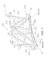
- FIG. 7 is a perspective view of a truss unit of the truss structure according to the embodiment.
- FIG. 8 is a perspective view of a spoke attachment member according to the embodiment.
- FIG. 9 is a partially enlarged cross-sectional view of the bicycle rim according to the other embodiment.
- a bicycle 1 includes a frame 3 , a handle 5 , front and rear wheels 7 , 9 .
- the handle 5 is fixed to a front fork 11 which is rotatably attached to the frame 3 .
- the front wheel 7 is rotatably attached to a pair of end portions 11 a of the front fork 11 via a front hub assembly 13 .
- the rear wheel 9 is rotatably attached to a pair of rear end portions 3 a of the frame 3 via a rear hub assembly 15 .
- Each of the front and rear wheels 7 , 9 includes a plurality of spokes 21 and a bicycle rim 25 .
- a bicycle tire 23 is configured to be attached to the bicycle rim 25 .
- the plurality of spokes 21 of the front wheel 7 connect the bicycle rim 25 to the front hub assembly 13 .
- the plurality of spokes 21 of the rear wheel 9 connect the bicycle rim 25 to the rear hub assembly 15 .
- the bicycle tire 23 is a separate member from the bicycle rim 25 .
- the bicycle rim 25 comprises the base member 27 , the cover member 29 , and the spoke attachment member 31 .
- the base member 27 preferably includes a truss structure 33 that defines the at least one opening S. More preferably, the base member 27 may include an annular truss structure 33 that defines a plurality of openings S.
- the cover member 29 at least partly covers the at least one opening S of the base member 27 .
- the spoke attachment member 31 is a separate member from the base member 27 and the cover member 29 . The spoke attachment member 31 is non-rotatably attached to the base member 27 .
- the base member 27 may preferably have an annular shape so that the bicycle rim 25 comprises an annular base member 27 , a cover member 29 , and a spoke attachment member 31 .
- the annular base member 27 has at least one opening S.
- the cover member 29 at least partly covers the at least one opening S of the annular base member 27 .
- the spoke attachment member 31 is a separate member from the annular base member 27 and the cover member 29 .
- the spoke attachment member 31 is non-rotatably attached to the annular base member 27 .
- the term “base member” also means an annular base member.
- the base member 27 can be an example of an annular base member so that the term “base member 27 ” is interchangeable with the term “annular base member 27 ”.
- the base member 27 is formed in a substantially annular shape.
- the base member 27 defines the at least one opening S.
- the base member 27 may have the at least one opening S.
- the base member 27 includes the truss structure 33 that defines the at least one opening S.
- the base member 27 includes the truss structure 33 that defines a plurality of openings S.
- the base member 27 may have a plurality of openings S. At least part of each of the plurality of openings S is provided on a radially outside from the spoke attachment member 31 .
- the truss structure 33 is formed in a substantially annular shape.
- the truss structure 33 preferably includes at least one slanting member 35 that intersects with a radial direction with respect to a rotational center axis O of the bicycle rim 25 .
- the truss structure 33 further includes at least one radially extending member 37 with respect to the rotational center axis O.
- the base member 27 may include at least one slanting member 35 that intersects with a radial direction with respect to a rotational center axis O of the bicycle rim 25 .
- the base member 27 may further include at least one radially extending member 37 with respect to the rotational center axis O.
- the truss structure 33 preferably includes a plurality of the slanting members 35 that intersect with the radial direction with respect to the rotational center axis O of the bicycle rim 25 .
- the truss structure 33 further includes a plurality of the radially extending members 37 with respect to the rotational center axis O.
- the base member 27 may include a plurality of the slanting members 35 that intersect with the radial direction with respect to the rotational center axis O of the bicycle rim 25 .
- the base member 27 may further include a plurality of the radially extending members 37 with respect to the rotational center axis O.
- the truss structure 33 includes a pair of the slanting members 35 a , 35 b that intersect with the radial direction with respect to the rotational center axis O of the bicycle rim 25 , and a junction 39 joining the pair of slanting members 35 a , 35 b.
- the truss structure 33 includes a plurality of first and second pairs of the slanting members 135 a , 135 b , 235 a , 235 b , the plurality of the radially extending members 37 , and a plurality of the junctions 39 .
- the truss structure may further include an inner periphery member 41 .
- the plurality of first pairs of slanting members 135 a , 135 b are arranged side by side in a circumferential direction with respect to the rotational center axis O.
- the first pair of slanting members 135 a , 135 b includes a first slanting member 135 a and a second slanting member 135 b .
- the first slanting member 135 a and the second slanting member 135 b are arranged adjacent to each other in the circumferential direction.
- the first slanting member 135 a extends radially outside from the junction 39 with an inclination. A radially inner portion of the first slanting member 135 a is attached to the junction 39 . A radially outer portion of the first slanting member 135 a is attached to a radially outer portion of the second slanting member 135 b.
- the second slanting member 135 b extends radially outside from the junction 39 with an inclination. A radially inner portion of the second slanting member 135 b is attached to the junction 39 . A radially outer portion of the second slanting member 135 b is attached to the radially outer portion of the first slanting member 135 a.
- the plurality of second pairs of slanting members 235 a , 235 b are arranged side by side in the circumferential direction.
- the plurality of second pairs of slanting members 235 a , 235 b are arranged at an interval with the plurality of first pairs of slanting members 135 a , 135 b in an axial direction parallel to the rotational center axis O.
- the second pair of slanting members 235 a , 235 b includes a third slanting member 235 a and a fourth slanting member 235 b .
- the third slanting member 235 a and the fourth slanting member 235 b are arranged adjacent to each other in the circumferential direction.
- the third slanting member 235 a is arranged opposed to the first slanting member 135 a in the axial direction.
- the third slanting member 235 a extends radially outside from the junction 39 with an inclination.
- a radially inner portion of the third slanting member 235 a is attached to the junction 39 .
- a radially outer portion of the third slanting member 235 a is attached to a radially outer portion of the fourth slanting member 235 b as illustrated in FIG. 6 .
- the fourth slanting member 235 b is arranged opposed to the second slanting member 135 b in the axial direction.
- the fourth slanting member 235 b extends radially outside from the junction 39 with an inclination.
- a radially inner portion of the fourth slanting member 235 b is attached to the junction 39 .
- a radially outer portion of the fourth slanting member 235 b is attached to a radially outer portion of the third slanting member 235 a.
- the plurality of radially extending members 37 extend along the radial direction with respect to the rotational center axis O.
- the plurality of radially extending members 37 include a plurality of first radially extending members 37 a , a plurality of second radially extending members 37 b , a plurality of third radially extending members 37 c , and a plurality of fourth radially extending members 37 d.
- the plurality of first radially extending members 37 a are arranged at an interval apart from each other in the circumferential direction.
- Each of the first radially extending members 37 a is arranged between the first slanting member 135 a and the second slanting member 135 b in the circumferential direction.
- a radially inner portion of each of the plurality of the first radially extending members 37 a is attached to the junction 39 .
- Each of the first radially extending members 37 a extends radially outside from the junction 39 .
- the plurality of second radially extending members 37 b are arranged at an interval apart from each other in the circumferential direction. Each of the second radially extending members 37 b is arranged between the adjacent first radially extending members 37 a in the circumferential direction.
- a radially outer portion of each of the plurality of the second radially extending members 37 b is attached to the radially outer portions of the first slanting member 135 a and the second slanting member 135 b .
- Each of the second radially extending members 37 b extends radially inside from the radially outer portions of the first slanting member 135 a and the second slanting member 135 b.
- Each of the plurality of third radially extending members 37 c is arranged opposed to the first radially extending member 37 a in the axial direction.
- the plurality of third radially extending members 37 c are arranged at an interval apart from each other in the circumferential direction.
- each of the plurality of the third radially extending members 37 c is attached to the junction 39 .
- Each of the third radially extending members 37 c is arranged between the third slanting member 235 a and the fourth slanting member 235 b in the circumferential direction.
- Each of the plurality of fourth radially extending members 37 d is arranged opposed to the second radially extending member 37 b in the axial direction.
- the plurality of fourth radially extending members 37 d are arranged at an interval apart from each other in the circumferential direction.
- each of the plurality of fourth radially extending members 37 d is attached to the radially outer portions of the third slanting member 235 a and the fourth slanting member 235 b .
- Each of the fourth radially extending members 37 d is arranged between the third slanting member 235 a and the fourth slanting member 235 b in the circumferential direction.
- a first spacing portion 37 e is formed on each of the first radially extending member 37 a and the second radially extending member 37 b .
- the first spacing portion 37 e of the first radially extending member 37 a projects toward the third radially extending member 37 c in the axial direction.
- the first spacing portion 37 e of the second radially extending member 37 b projects toward the fourth radially extending member 37 d in the axial direction.
- a second spacing portion 37 f is formed on each of the third radially extending member 37 c and the fourth radially extending member 37 d .
- the second spacing portion 37 f of the third radially extending member 37 c projects toward the first radially extending member 37 a in the axial direction.
- the second spacing portion 37 f of the fourth radially extending member 37 d projects toward the second radially extending member 37 b in the axial direction.
- the first spacing portion 37 e and the second spacing portion 37 f are attached to each other. Specifically, the first spacing portion 37 e and the second spacing portion 37 f are fixed each other in a state where the first spacing portion 37 e and the second spacing portion 37 f abut on each other. In the embodiment, the first spacing portion 37 e and the second spacing portion 37 f are attached to each other by adhesive. Alternatively, the first spacing portion 37 e and the second spacing portion 37 f are attached to each other by a mechanical fastener, such as a rivet, a bolt, and so on.
- a mechanical fastener such as a rivet, a bolt, and so on.
- An axially distance between the first radially extending member 37 a and the third radially extending member 37 c is held at a predetermined interval by the abutment of the first and second spacing portions 37 e , 37 f
- an axially distance between the second radially extending member 37 b and the fourth radially extending member 37 d is held at a predetermined interval by the abutment of the first and second spacing portions 37 e , 37 f.
- the truss structure 33 includes the pair of the slanting members 35 a , 35 b that intersect with the radial direction with respect to the rotational center axis O of the bicycle rim 25 , and the junction 39 joining the pair of slanting members 35 a , 35 b .
- the truss structure 33 further includes a radially extending member 37 with respect to the rotational center axis O. As shown in FIGS. 3 to 6 , the junction 39 joins the pair of slanting members 35 a , 35 b and the radially extending member 37 .
- the base member 27 may include the pair of the slanting members 35 a , 35 b that intersect with the radial direction with respect to the rotational center axis O of the bicycle rim 25 , and the junction 39 joining the pair of slanting members 35 a , 35 b .
- the base member 27 may further include a radially extending member 37 with respect to the rotational center axis O.
- the junction 39 joins the pair of slanting members 35 a , 35 b and the radially extending member 37 .
- each of the plurality of junctions 39 joins the first pair of the slanting members 135 a , 135 b and the second pair of slanting members 235 a , 235 b , and the radially extending members 37 (the first radially extending member 37 a and the third radially extending members 37 c ).
- each of the junctions 39 includes a first junction portion 39 a and a second junction portion 39 b .
- the first junction portion 39 a joins the first slanting member 135 a , the third slanting member 235 a , the first radially extending member 37 a , and the third radially extending members 37 c .
- the first junction portion 39 a is provided on a radially inner portion of the first slanting member 135 a , a radially inner portion of the third slanting member 235 a , and a radially inner portion of the first radially extending member 37 a.
- the second junction portion 39 b joins the second slanting member 135 b and the fourth slanting member 235 b .
- the second junction portion 39 b is provided on a radially inner portion of the second slanting member 135 b , a radially inner portion of the fourth slanting member 235 b , and a radially inner portion of the third radially extending members 37 c.
- the second junction portion 39 b is disposed adjacent to the first junction portion 39 a in the circumferential direction.
- the second junction portion 39 b is attached to the first junction portion 39 a .
- the second junction portion 39 b is attached to the first junction portion 39 a by adhesive.
- the inner periphery member 41 is formed in a substantially annular shape.
- the inner periphery member 41 is attached to the plurality of junction 39 .
- the inner periphery member 41 may define the plurality of openings S with the slanting members 35 and the radially extending members 37 .
- the inner periphery member 41 includes a plurality of arc portions 41 a .
- Each of the plurality of arc portions 41 a is formed in a substantially arc shape.
- the plurality of arc portions 41 a are arranged side by side in the circumferential direction on an inner peripheral side of the base member 27 . Specifically, each of the plurality of arc portions 41 a is arranged between the adjacent junctions 39 in the circumferential direction.
- Each of the plurality of arc portions 41 a is attached to the junctions 39 . Also, each of the plurality of arc portions 41 a is attached to the spoke attachment members 31 .
- each of the plurality of arc portions 41 a is attached to the first junction portion 39 a , the second junction portion 39 b , and the radially inner portions of the second radially extending member 37 b and the fourth radially extending member 37 d .
- the inner periphery member 41 may be integrally formed as a unitary one-piece member.
- the plurality of openings S of the base member 27 are formed by at least one of the first to fourth slanting members 135 a , 135 b , 235 a , 235 b and at least one of the first to fourth radially extending members 37 a , 37 b , 37 c , 37 d .
- At least one of the arc portions 41 a may form the plurality of openings S with at least one of the first to fourth slanting members 135 a , 135 b , 235 a , 235 b and at least one of the first to fourth radially extending members 37 a , 37 b , 37 c , 37 d.
- the truss structure 33 including the above configuration is assembled with a plurality of truss units 133 , as shown in FIG. 7 .
- Each of the plurality of truss units 133 includes the first pair of slanting members 135 a , 135 b (the first and second slanting members 135 a , 135 b ), the second pair of slanting members 235 a , 235 b (the third and fourth slanting members 235 a , 235 b ), the radially extending members 37 (the first to fourth radially extending members 37 a , 37 b , 37 c , 37 d ), and the arc portion 41 a .
- the truss structure 33 is formed by connecting the plurality of truss units 133 to each other in the circumferential direction.
- the plurality of truss units 133 is attached to each other by adhesive.
- the plurality of truss units 133 may also be attached to each other by a mechanical fastener, such as a rivet, a bolt, and so on.
- the cover member 29 preferably has an annular shape.
- the cover member 29 may have a non-annular shape.
- the cover member 29 is a separate member from the tire 23 .
- the tire 23 is disposed on a radially outer side of the cover member 29 (see FIG. 1 ).
- the cover member 29 covers the truss structure 33 of the base member 27 from outside of the truss structure 33 .
- the cover member 29 completely covers the at least one opening S of the base member 27 .
- the cover member 29 completely covers the plurality of openings S of the base member 27 .
- the cover member 29 has a radially outer peripheral part 29 a and a radially inner peripheral part 29 b .
- the radially inner peripheral part 29 b is included in a first cover portion 43 (described as follows).
- the radially outer peripheral part 29 a is included in a second cover portion 45 (described as follows).
- the cover member 29 includes the first cover portion 43 and the second cover portion 45 .
- the first cover portion 43 is attached to the second cover portion 45 in a state where the bicycle rim 25 is assembled.
- the cover member 29 includes a pair of the first cover portions 43 a , 43 b and the second cover portion 45 .
- the pair of first cover portions 43 a , 43 b are attached to the second cover portion 45 in a state where the bicycle rim 25 is assembled.
- the pair of first cover portions 43 a , 43 b are formed in a substantially annular shape. One of the pair of first cover portion 43 a , 43 b is arranged opposed to the other of the pair of first cover portion 43 a , 43 b in the axial direction.
- One of the pair of first cover portions 43 a , 43 b is attached to the inner periphery member 41 (the plurality of arc portions 41 a ) and a first side portion 27 c (see FIGS. 6 and 7 ) of the base member 27 .
- the first side portion 27 c of the base member 27 is formed by the plurality of first pairs of slanting members 135 a , 135 b (the first slanting members 135 a and the second slanting members 135 b ), the first radially extending members 37 a , and the second radially extending members 37 b (see FIGS. 6 and 7 ).
- the other of the pair of first cover portion 43 a , 43 b is attached to the inner periphery member 41 (the plurality of arc portions 41 a ) and a second side portion 27 d (see FIGS. 6 and 7 ) of the base member 27 .
- the second side portion 27 d is formed by the plurality of second pairs of slanting members 235 a , 235 b (the third slanting members 235 a and the fourth slanting members 235 b ), the third radially extending members 37 c , and the fourth radially extending members 37 d (see FIGS. 6 and 7 ).
- the inner circumference portion of the pair of first cover portions 43 a , 43 b forms the radially inner peripheral part 29 b of the cover member 29 .
- the spoke attachment member 31 is attached to the radially inner peripheral part 29 b .
- each of the spoke attachment members 31 is attached to the radially inner peripheral part 29 b .
- each of the spoke attachment members 31 is attached to hollow portion 47 provided on the pair of first cover portions 43 a , 43 b (see FIG. 5 ).
- the second cover portion 45 is formed in a substantially annular shape.
- the second cover portion 45 is attached to a radially outer portion of the base member 27 .
- the second cover portion 45 is attached to the radially outer portion of the truss structure 33 and radially outer portions 43 c of the pair of first cover portions 43 a , 43 b.
- the outer circumference portion of the second cover portion 45 forms the radially outer peripheral part 29 a of the cover member 29 .
- the tire 23 is disposed on the radially outer peripheral part 29 a of the cover member 29 .
- each of the spokes 21 is attached to the spoke attachment member 31 .
- one end of the spoke 21 is attached to the spoke attachment member 31
- the other end of the spoke 21 is attached to the front hub assembly 13 or the rear hub assembly 15 (see FIG. 1 ).
- the base member 27 has a radially outer peripheral part 27 a and a radially inner peripheral part 27 b .
- the spoke attachment member 31 is attached to the radially inner peripheral part 27 b of the base member 27 .
- the spoke attachment member 31 is attached to the radially inner peripheral part 29 b of the cover member 29 .
- the spoke attachment member 31 is attached to the junction 39 .
- the spoke attachment member 31 includes a tubular portion 31 a and a projecting portion 31 b extending from the tubular portion 31 a .
- the spoke attachment member 31 includes the tubular portion 31 a and a pair of projecting portions 31 b that each extend from the tubular portion 31 a.
- the tubular portion 31 a is formed in a substantially tubular shape.
- the spoke 21 is attached to the tubular portion 31 a .
- the one end of the spoke 21 is attached to an inner peripheral portion of the tubular portion 31 a.
- the pair of projecting portions 31 b function as rotation stopper of the tubular portion 31 a .
- the projecting portion 31 b is integrally formed on the tubular portion 31 a in the embodiment.
- the projecting portion 31 b can be a separate member from the tubular portion 31 a .
- Each of the pair of projecting portions 31 b extends outside from an outer peripheral surface of the tubular portion 31 a .
- the pair of projecting portions 31 b are arranged at an interval apart from each other in a circumferential direction of the tubular portion 31 a.
- the tubular portion 31 a and the pair of projecting portions 31 b are disposed between the first junction portion 39 a and the second junction portion 39 b that are adjacent to each other in the circumferential direction.
- the tubular portion 31 a and the pair of projecting portions 31 b are clamped by the first junction portion 39 a and the second junction portion 39 b .
- the tubular portion 31 a and the pair of projecting portions 31 b are attached to the first junction portion 39 a and the second junction portion 39 b by adhesive.
- each member of the bicycle rim 25 is formed as follows.
- the base member 27 has a first wear-resistance.
- the base member 27 has a first specific gravity.
- the base member 27 is made of a non-metallic material.
- the base member 27 is made of a fiber-reinforced plastic.
- the truss structure 33 of the base member 27 is preferably formed by injection molding.
- the cover member 29 has a second wear-resistance that is larger than the first wear-resistance.
- the cover member 29 has a second specific gravity that is larger than the first specific gravity.
- the cover member 29 is made of a metallic material.
- the cover member 29 is made of aluminum.
- the spoke attachment member 31 has a third wear-resistance that is larger than the first wear-resistance.
- the spoke attachment member 31 has a third specific gravity that is larger than the first specific gravity.
- the spoke attachment member 31 is made of a metallic material.
- the spoke attachment member 31 is made of aluminum.
- the spoke attachment member 31 is preferably shaped by forging.
- the truss structure 33 includes a plurality of truss units 133 .
- the truss structure 33 is formed as a unitary unit.
- the cover member 29 can include the brake contact surfaces.
- the brake contact surfaces are respectively formed on side portions 29 c of the cover member 29 , for example, in the first cover portions 43 a , 43 b.
- the first cover portions 43 a , 43 b are made of a metallic material
- the second cover portion 45 is made of a non-metallic material, for example, a fiber-reinforced plastic.
- cover member 29 includes the pair of first cover portion 43 a , 43 b .
- the pair of first cover portion 43 a , 43 b can be integrally formed as a unitary one-piece member.
- the cover member 29 can also include equal to or more than 3 piece members.
- spoke attachment member 31 includes the pair of projecting portions 31 b .
- spoke attachment member 31 can include a single projecting portion 31 b only.
- the spoke attachment member 31 can also include equal to or more than 3 projecting portions 31 b.
- the spoke attachment member 31 can be disposed between a pair of junction portions provided so as to be adjacent to each other in the axial direction.
- one of the pair of junction portions are provided on a radially inner portions of the first and second slanting members 135 a , 135 b , and a radially inner portions of the first radially extending members 37 a .
- the other of the pair of junction portions is provide on a radially inner portions of the third and fourth slanting members 235 a , 235 b , and a radially inner portions of the third radially extending members 37 c.
- the term “comprising” and its derivatives, as used herein, are intended to be open ended terms that specify the presence of the stated features, elements, components, groups, integers, and/or steps, but do not exclude the presence of other unstated features, elements, components, groups, integers and/or steps.
- the foregoing also applies to words having similar meanings such as the terms, “including”, “having” and their derivatives.
- the terms “part,” “section,” “portion,” “member” or “element” when used in the singular can have the dual meaning of a single part or a plurality of parts.
- the following directional terms “forward”, “rearward”, “above”, “downward”, “vertical”, “horizontal”, “below”, “transverse”, “inward” and “outward” as well as any other similar directional terms refer to those directions of the bicycle rim in a state the bicycle rim is mounted to a bicycle. Accordingly, these terms, as utilized to describe the present technology should be interpreted relative to the bicycle rim.
Landscapes
- Engineering & Computer Science (AREA)
- Mechanical Engineering (AREA)
- Chemical & Material Sciences (AREA)
- Materials Engineering (AREA)
- Tires In General (AREA)
- Braking Arrangements (AREA)
- Axle Suspensions And Sidecars For Cycles (AREA)
Abstract
A bicycle rim comprises a base member, a cover member, and a spoke attachment member. The base member includes a truss structure that defines at least one opening. The cover member at least partly covers the at least one opening of the base member. The spoke attachment member is a separate member from the base member and the cover member. The spoke attachment member is non-rotatably attached to the base member.
Description
The technology disclosed herein relates to a bicycle rim.
In recent years, various efforts have been made to not only reduce weight of bicycle members but also ensure stiffness of the bicycle members.
It is an object of the present invention to provide a bicycle rim capable of reducing weight thereof and ensuring sufficient stiffness thereof.
In accordance with a first aspect of the present invention, a bicycle rim comprises a base member, a cover member, and a spoke attachment member. The base member includes a truss structure that defines at least one opening. The cover member at least partly covers the at least one opening of the base member. The spoke attachment member is a separate member from the base member and the cover member. The spoke attachment member is non-rotatably attached to the base member.
With the bicycle rim according to the first aspect, the bicycle rim is capable of reducing weight thereof and ensuring sufficient stiffness thereof, because the bicycle rim comprises the base member including a truss structure, the cover member, and the spoke attachment member that is a separate member from the base member and the cover member.
In accordance with a second aspect of the present invention, the bicycle rim according to the first aspect is configured so that the truss structure includes at least one slanting member that intersects with a radial direction with respect to a rotational center axis of the bicycle rim.
With the bicycle rim according to the second aspect, the bicycle rim is capable of withstanding forces from multiple direction, because the truss structure includes at least one slanting member that intersects with a radial direction with respect to a rotational center axis of the bicycle rim. In other words, the bicycle rim is capable of reducing weight thereof and ensuring sufficient stiffness thereof.
In accordance with a third aspect of the present invention, the bicycle rim according to the second aspect is configured so that the truss structure further includes at least one radially extending member with respect to the rotational center axis.
With the bicycle rim according to the third aspect, the bicycle rim is capable of effectively withstanding forces from multiple direction, because the truss structure includes at least one radially extending member besides at least one slanting member. In other words, the bicycle rim is capable of reducing weight thereof and effectively ensuring sufficient stiffness thereof.
In accordance with a fourth aspect of the present invention, the bicycle rim according to any one of the first to third aspects is configured so that the truss structure includes a plurality of slanting members that intersect with a radial direction with respect to a rotational center axis of the bicycle rim.
With the bicycle rim according to the fourth aspect, the bicycle rim is capable of withstanding forces from multiple direction, because the truss structure includes a plurality of slanting members. In other words, the bicycle rim is capable of reducing weight thereof and ensuring sufficient stiffness thereof.
In accordance with a fifth aspect of the present invention, the bicycle rim according to the fourth aspect is configured so that the truss structure further includes a plurality of radially extending members with respect to the rotational center axis.
With the bicycle rim according to the fifth aspect, the bicycle rim is capable of effectively withstanding forces from multiple direction, because the truss structure includes a plurality of radially extending members besides at least one slanting member. In other words, the bicycle rim is capable of reducing weight thereof and effectively ensuring sufficient stiffness thereof.
In accordance with a sixth aspect of the present invention, the bicycle rim according to any one of the first to fifth aspects is configured so that the truss structure defines a plurality of openings.
With the bicycle rim according to the sixth aspect, the bicycle rim is capable of realizing further weight reduction thereof.
In accordance with a seventh aspect of the present invention, the bicycle rim according to any one of the first to sixth aspects is configured so that the base member has a radially outer peripheral part and a radially inner peripheral part. The spoke attachment member is attached to the radially inner peripheral part of the base member.
With the bicycle rim according to the seventh aspect, the bicycle rim is capable of realizing further weight reduction thereof, because it is possible to avoid lengthening a total length of a spoke by the above configuration.
In accordance with a eighth aspect of the present invention, the bicycle rim according to any one of the first to seventh aspects is configured so that the cover member has a radially outer peripheral part and a radially inner peripheral part. The spoke attachment member is attached to the radially inner peripheral part of the cover member.
With the bicycle rim according to the eighth aspect, the bicycle rim is capable of realizing further weight reduction thereof, because it is possible to avoid lengthening a total length of a spoke by the above configuration.
In accordance with a ninth aspect of the present invention, the bicycle rim according to any one of the first to eighth aspects is configured so that the truss structure includes a pair of slanting members that intersect with a radial direction with respect to a rotational center axis of the bicycle rim, and a junction joining the pair of slanting members.
With the bicycle rim according to the ninth aspect, the bicycle rim is capable of improving stiffness thereof, because the truss structure includes a pair of slanting members and a junction.
In accordance with a tenth aspect of the present invention, the bicycle rim according to the ninth aspect is configured so that the spoke attachment member is attached to the junction.
With the bicycle rim according to the tenth aspect, the bicycle rim is capable of improving stiffness thereof.
In accordance with an eleventh aspect of the present invention, the bicycle rim according to the ninth or tenth aspect is configured so that the truss structure includes a radially extending member with respect to the rotational center axis. The junction joins the pair of slanting members and the radially extending member.
With the bicycle rim according to the eleventh aspect, the bicycle rim is capable of improving stiffness thereof.
In accordance with a twelfth aspect of the present invention, the bicycle rim according to any one of the first to eleventh aspects is configured so that the cover member completely covers the at least one opening of the base member.
With the bicycle rim according to the twelfth aspect, the bicycle rim is capable of improving an aerodynamic characteristic thereof.
In accordance with a thirteenth aspect of the present invention, the bicycle rim according to any one of the first to twelfth aspects is configured so that the cover member completely covers the plurality of openings of the base member.
With the bicycle rim according to the thirteenth aspect, the bicycle rim is capable of improving an aerodynamic characteristic thereof.
In accordance with a fourteenth aspect of the present invention, the bicycle rim according to any one of the first to thirteenth aspects is configured so that the base member is made of a non-metallic material.
With the bicycle rim according to the fourteenth aspect, the bicycle rim is capable of realizing weight reduction thereof.
In accordance with a fifteenth aspect of the present invention, the bicycle rim according to the fourteenth aspect is configured so that the base member is made of a fiber-reinforced plastic.
With the bicycle rim according to the fifteenth aspect, the bicycle rim is capable of realizing weight reduction thereof and ensuring sufficient stiffness thereof.
In accordance with a sixteenth aspect of the present invention, the bicycle rim according to the fourteenth aspect is configured so that the truss structure of the base member is formed by injection molding.
With the bicycle rim according to the sixteenth aspect, productivity of the bicycle rim can be improved.
In accordance with a seventeenth aspect of the present invention, the bicycle rim according to any one of the first to sixteenth aspects is configured so that the cover member is made of a metallic material.
With the bicycle rim according to the seventeenth aspect, the bicycle rim is capable of realizing weight reduction thereof and ensuring sufficient stiffness thereof.
In accordance with an eighteenth aspect of the present invention, the bicycle rim according to the seventeenth aspect is configured so that the cover member is made of aluminum.
With the bicycle rim according to the eighteenth aspect, the bicycle rim is capable of realizing weight reduction thereof and ensuring sufficient stiffness thereof.
In accordance with a nineteenth aspect of the present invention, the bicycle rim according to any one of the first to eighteenth aspects is configured so that the spoke attachment member is made of a metallic material.
With the bicycle rim according to the nineteenth aspect, the bicycle rim is capable of realizing weight reduction thereof and ensuring sufficient stiffness thereof.
In accordance with a twentieth aspect of the present invention, the bicycle rim according to the nineteenth aspect is configured so that the spoke attachment member is made of aluminum.
With the bicycle rim according to the twentieth aspect, the bicycle rim is capable of realizing weight reduction thereof and ensuring sufficient stiffness thereof.
In accordance with a twenty first aspect of the present invention, the bicycle rim according to the nineteenth or twentieth aspect is configured so that the spoke attachment member is shaped by forging.
With the bicycle rim according to the twenty first aspect, productivity of the bicycle rim can be improved.
In accordance with a twenty second aspect of the present invention, the bicycle rim according to any one of the first to twenty first aspects is configured so that the spoke attachment member includes a tubular portion and a projecting portion extending from the tubular portion.
With the bicycle rim according to the twenty second aspect, rotation of the spoke attachment member is effectively restricted by the above configuration.
In accordance with a twenty third aspect of the present invention, the bicycle rim according to any one of the first to twenty second aspects is configured so that the base member has a first wear-resistance. The cover member has a second wear-resistance that is larger than the first wear-resistance. The spoke attachment member has a third wear-resistance that is larger than the first wear-resistance.
With the bicycle rim according to the twenty third aspect, the bicycle rim is capable of ensuring sufficient wear resistant thereof and realizing weight reduction thereof.
In accordance with a twenty fourth aspect of the present invention, the bicycle rim according to any one of the first to twenty third aspects is configured so that the base member has a first specific gravity. The cover member has a second specific gravity that is larger than the first specific gravity. The spoke attachment member has a third specific gravity that is larger than the first specific gravity.
With the bicycle rim according to the twenty fourth aspect, the bicycle rim is capable of ensuring sufficient stiffness thereof and realizing weight reduction thereof.
In accordance with a twenty fifth aspect of the present invention, the bicycle rim according to any one of the first to twenty fourth aspects is configured so that the cover member includes a first cover portion and a second cover portion. The first cover portion is attached to the second cover portion in a state where the bicycle rim is assembled.
With the bicycle rim according to the twenty fifth aspect, productivity of the bicycle rim can be improved.
In accordance with a twenty sixth aspect of the present invention, the bicycle rim according to any one of the first to twenty fifth aspects is configured so that the base member includes an annular truss structure that defines a plurality of openings.
With the bicycle rim according to the twenty sixth aspect, the bicycle rim is capable of reducing weight thereof and ensuring sufficient stiffness thereof.
In accordance with a twenty seventh aspect of the present invention, the bicycle rim according to any one of the first to twenty sixth aspects is configured so that the cover member has an annular shape.
With the bicycle rim according to the twenty seventh aspect, the bicycle rim is capable of reducing weight thereof and ensuring sufficient stiffness thereof.
In accordance with a twenty eighth aspect of the present invention, a bicycle rim comprises an annular base member, a cover member, and a spoke attachment member. The annular base member has at least one opening. The cover member at least partly covers the at least one opening of the base member. The spoke attachment member is a separate member from the base member and the cover member. The spoke attachment member is non-rotatably attached to the base member.
With the bicycle rim according to the twenty eighth aspect, the bicycle rim is capable of reducing weight thereof and ensuring sufficient stiffness thereof, because the bicycle rim comprises the annular base member having at least one opening, the cover member, and the spoke attachment member that is a separate member from the base member and the cover member.
In accordance with a twenty ninth aspect of the present invention, the bicycle rim according to the twenty eighth aspect is configured so that the annular base member includes at least one slanting member that intersects with a radial direction with respect to a rotational center axis of the bicycle rim.
With the bicycle rim according to the twenty ninth aspect, the bicycle rim is capable of withstanding forces from multiple direction, because the annular base member includes at least one slanting member that intersects with a radial direction with respect to a rotational center axis of the bicycle rim. In other words, the bicycle rim is capable of reducing weight thereof and ensuring sufficient stiffness thereof.
In accordance with a thirtieth aspect of the present invention, the bicycle rim according to the twenty eighth or twenty ninth aspect is configured so that the annular base member further includes at least one radially extending member with respect to the rotational center axis.
With the bicycle rim according to the thirtieth aspect, the bicycle rim is capable of effectively withstanding forces from multiple direction, because the annular base member includes at least one radially extending member besides at least one slanting member. In other words, the bicycle rim is capable of reducing weight thereof and effectively ensuring sufficient stiffness thereof.
In accordance with a thirty first aspect of the present invention, the bicycle rim according to any one of the twenty eighth to thirtieth aspects is configured so that the annular base member includes a plurality of slanting members that intersect with a radial direction with respect to a rotational center axis of the bicycle rim.
With the bicycle rim according to the thirty first aspect, the bicycle rim is capable of withstanding forces from multiple direction, because the annular base member includes a plurality of slanting members. In other words, the bicycle rim is capable of reducing weight thereof and ensuring sufficient stiffness thereof.
In accordance with a thirty second aspect of the present invention, the bicycle rim according to the thirty first aspect is configured so that the annular base member further includes a plurality of radially extending members with respect to the rotational center axis.
With the bicycle rim according to the thirty second aspect, the bicycle rim is capable of effectively withstanding forces from multiple direction, because the annular base member includes at least one slanting member and the plurality of radially extending members. In other words, the bicycle rim is capable of reducing weight thereof and effectively ensuring sufficient stiffness thereof.
In accordance with a thirty third aspect of the present invention, the bicycle rim according to any one of the twenty eighth to thirty second aspects is configured so that the annular base member has a plurality of openings.
With the bicycle rim according to the thirty third aspect, the bicycle rim is capable of realizing further weight reduction thereof.
In accordance with a thirty fourth aspect of the present invention, the bicycle rim according to any one of the twenty eighth to thirty third aspects is configured so that the cover member completely covers the at least one opening of the annular base member.
With the bicycle rim according to the thirty fourth aspect, the bicycle rim is capable of improving an aerodynamic characteristic thereof.
In accordance with a thirty fifth aspect of the present invention, the bicycle rim according to any one of the twenty eighth to thirty fourth aspects is configured so that the cover member completely covers the plurality of openings of the annular base member.
With the bicycle rim according to the thirty fifth aspect, the bicycle rim is capable of improving an aerodynamic characteristic thereof.
In accordance with a thirty sixth aspect of the present invention, the bicycle rim according to any one of the twenty eighth to thirty fifth aspects is configured so that the annular base member has a radially outer peripheral part and a radially inner peripheral part. The spoke attachment member is attached to the radially inner peripheral part of the annular base member.
With the bicycle rim according to the thirty sixth aspect, the bicycle rim is capable of realizing further weight reduction thereof, because it is possible to avoid lengthening a total length of a spoke by the above configuration.
In accordance with a thirty seventh aspect of the present invention, the bicycle rim according to any one of the twenty eighth to thirty sixth aspects is configured so that the cover member has a radially outer peripheral part and a radially inner peripheral part. The spoke attachment member is attached to the radially inner peripheral part of the cover member.
With the bicycle rim according to the thirty seventh aspect, the bicycle rim is capable of realizing further weight reduction thereof, because it is possible to avoid lengthening a total length of a spoke by the above configuration.
In accordance with a thirty eighth aspect of the present invention, the bicycle rim according to any one of the twenty eighth to thirty seventh aspects is configured so that the annular base member includes a pair of slanting members that intersect with a radial direction with respect to a rotational center axis of the bicycle rim, and a junction joining the pair of slanting members.
With the bicycle rim according to the thirty eighth aspect, the bicycle rim is capable of improving stiffness thereof, because the annular base member includes a pair of slanting members and a junction.
In accordance with a thirty ninth aspect of the present invention, the bicycle rim according to the thirty eighth aspect is configured so that the spoke attachment member is attached to the junction.
With the bicycle rim according to the thirty ninth aspect, the bicycle rim is capable of improving stiffness thereof.
In accordance with a fortieth aspect of the present invention, the bicycle rim according to the thirty eighth or thirty ninth aspect is configured so that the annular base member includes a radially extending member with respect to the rotational center axis. The junction joins the pair of slanting members and the radially extending member.
With the bicycle rim according to the fortieth aspect, the bicycle rim is capable of improving stiffness thereof.
In accordance with a forty first aspect of the present invention, the bicycle rim according to any one of the twenty eighth to fortieth aspects is configured so that the annular base member is made of a non-metallic material.
With the bicycle rim according to the forty first aspect, the bicycle rim is capable of realizing weight reduction thereof.
In accordance with a forty second aspect of the present invention, the bicycle rim according to any one of the twenty eighth to forty first aspects is configured so that the annular base member is made of a fiber-reinforced plastic.
With the bicycle rim according to the forty second aspect, the bicycle rim is capable of realizing weight reduction thereof and ensuring sufficient stiffness thereof.
In accordance with a forty third aspect of the present invention, the bicycle rim according to any one of the twenty eighth to forty second aspects is configured so that the cover member is made of a metallic material.
With the bicycle rim according to the forty third aspect, the bicycle rim is capable of realizing weight reduction thereof and ensuring sufficient stiffness thereof.
In accordance with a forty fourth aspect of the present invention, the bicycle rim according to any one of the twenty eighth to forty third aspects is configured so that the cover member is made of aluminum.
With the bicycle rim according to the forty fourth aspect, the bicycle rim is capable of realizing weight reduction thereof and ensuring sufficient stiffness thereof.
In accordance with a forty fifth aspect of the present invention, the bicycle rim according to any one of the twenty eighth to forty forth aspects is configured so that the spoke attachment member is made of a metallic material.
With the bicycle rim according to the forty fifth aspect, the bicycle rim is capable of realizing weight reduction thereof and ensuring sufficient stiffness thereof.
In accordance with a forty sixth aspect of the present invention, the bicycle rim according to any one of the twenty eighth to forty fifth aspects is configured so that the spoke attachment member is made of aluminum.
With the bicycle rim according to the forty sixth aspect, the bicycle rim is capable of realizing weight reduction thereof and ensuring sufficient stiffness thereof.
In accordance with a forty seventh aspect of the present invention, the bicycle rim according to any one of the twenty eighth to forty sixth aspects is configured so that the spoke attachment member includes a tubular portion and a projecting portion extending from the tubular portion.
With the bicycle rim according to the forty seventh aspect, rotation of the spoke attachment member is effectively restricted by the above configuration.
In accordance with a forty eighth aspect of the present invention, the bicycle rim according to any one of the twenty eighth to forty seventh aspects is configured so that the annular base member has a first wear-resistance. The cover member has a second wear-resistance that is larger than the first wear-resistance. The spoke attachment member has a third wear-resistance that is larger than the first wear-resistance.
With the bicycle rim according to the forty eighth aspect, the bicycle rim is capable of ensuring sufficient wear resistant thereof and realizing weight reduction thereof.
In accordance with a forty ninth aspect of the present invention, the bicycle rim according to any one of the twenty eighth to forty eighth aspects is configured so that the annular base member has a first specific gravity. The cover member has a second specific gravity that is larger than the first specific gravity. The spoke attachment member has a third specific gravity that is larger than the first specific gravity.
With the bicycle rim according to the forty ninth aspect, the bicycle rim is capable of ensuring sufficient stiffness thereof and realizing weight reduction thereof.
Referring now to the attached drawings, which form a part of this original disclosure:
Selected embodiments of the present technology will now be explained with reference to the drawings. It will be apparent to those skilled in the art from this disclosure that the following descriptions of the embodiments of the present technology are provided for illustration only and not for the purpose of limiting the technology as defined by the appended claims and their equivalents.
As shown FIG. 1 , a bicycle 1 includes a frame 3, a handle 5, front and rear wheels 7, 9. The handle 5 is fixed to a front fork 11 which is rotatably attached to the frame 3. The front wheel 7 is rotatably attached to a pair of end portions 11 a of the front fork 11 via a front hub assembly 13. The rear wheel 9 is rotatably attached to a pair of rear end portions 3 a of the frame 3 via a rear hub assembly 15.
Each of the front and rear wheels 7, 9 includes a plurality of spokes 21 and a bicycle rim 25. A bicycle tire 23 is configured to be attached to the bicycle rim 25. The plurality of spokes 21 of the front wheel 7 connect the bicycle rim 25 to the front hub assembly 13. The plurality of spokes 21 of the rear wheel 9 connect the bicycle rim 25 to the rear hub assembly 15. The bicycle tire 23 is a separate member from the bicycle rim 25.
<Bicycle Rim>
As shown in FIGS. 2 to 4 , the bicycle rim 25 comprises the base member 27, the cover member 29, and the spoke attachment member 31. The base member 27 preferably includes a truss structure 33 that defines the at least one opening S. More preferably, the base member 27 may include an annular truss structure 33 that defines a plurality of openings S. The cover member 29 at least partly covers the at least one opening S of the base member 27. The spoke attachment member 31 is a separate member from the base member 27 and the cover member 29. The spoke attachment member 31 is non-rotatably attached to the base member 27.
The base member 27 may preferably have an annular shape so that the bicycle rim 25 comprises an annular base member 27, a cover member 29, and a spoke attachment member 31. The annular base member 27 has at least one opening S. The cover member 29 at least partly covers the at least one opening S of the annular base member 27. The spoke attachment member 31 is a separate member from the annular base member 27 and the cover member 29. The spoke attachment member 31 is non-rotatably attached to the annular base member 27. For the sake of brevity, hereinafter, the term “base member” also means an annular base member. Thus, the base member 27 can be an example of an annular base member so that the term “base member 27” is interchangeable with the term “annular base member 27”.
—Base Member—
As shown in FIGS. 3 and 4 , the base member 27 is formed in a substantially annular shape. The base member 27 defines the at least one opening S. Thus, the base member 27 may have the at least one opening S.
In the embodiment, the base member 27 includes the truss structure 33 that defines the at least one opening S. Specifically, the base member 27 includes the truss structure 33 that defines a plurality of openings S. In other words, the base member 27 may have a plurality of openings S. At least part of each of the plurality of openings S is provided on a radially outside from the spoke attachment member 31.
As shown in FIGS. 3 and 5 , the truss structure 33 is formed in a substantially annular shape. The truss structure 33 preferably includes at least one slanting member 35 that intersects with a radial direction with respect to a rotational center axis O of the bicycle rim 25. Preferably, the truss structure 33 further includes at least one radially extending member 37 with respect to the rotational center axis O. The base member 27 may include at least one slanting member 35 that intersects with a radial direction with respect to a rotational center axis O of the bicycle rim 25. Preferably, the base member 27 may further include at least one radially extending member 37 with respect to the rotational center axis O.
The truss structure 33 preferably includes a plurality of the slanting members 35 that intersect with the radial direction with respect to the rotational center axis O of the bicycle rim 25. Preferably, the truss structure 33 further includes a plurality of the radially extending members 37 with respect to the rotational center axis O. The base member 27 may include a plurality of the slanting members 35 that intersect with the radial direction with respect to the rotational center axis O of the bicycle rim 25. Preferably, the base member 27 may further include a plurality of the radially extending members 37 with respect to the rotational center axis O.
The truss structure 33 includes a pair of the slanting members 35 a, 35 b that intersect with the radial direction with respect to the rotational center axis O of the bicycle rim 25, and a junction 39 joining the pair of slanting members 35 a, 35 b.
In the embodiment, as shown in FIG. 6 , the truss structure 33 includes a plurality of first and second pairs of the slanting members 135 a, 135 b, 235 a, 235 b, the plurality of the radially extending members 37, and a plurality of the junctions 39. The truss structure may further include an inner periphery member 41.
—Slanting Member—
As shown in FIG. 6 , the plurality of first pairs of slanting members 135 a, 135 b are arranged side by side in a circumferential direction with respect to the rotational center axis O.
The first pair of slanting members 135 a, 135 b includes a first slanting member 135 a and a second slanting member 135 b. The first slanting member 135 a and the second slanting member 135 b are arranged adjacent to each other in the circumferential direction.
The first slanting member 135 a extends radially outside from the junction 39 with an inclination. A radially inner portion of the first slanting member 135 a is attached to the junction 39. A radially outer portion of the first slanting member 135 a is attached to a radially outer portion of the second slanting member 135 b.
The second slanting member 135 b extends radially outside from the junction 39 with an inclination. A radially inner portion of the second slanting member 135 b is attached to the junction 39. A radially outer portion of the second slanting member 135 b is attached to the radially outer portion of the first slanting member 135 a.
The plurality of second pairs of slanting members 235 a, 235 b are arranged side by side in the circumferential direction. The plurality of second pairs of slanting members 235 a, 235 b are arranged at an interval with the plurality of first pairs of slanting members 135 a, 135 b in an axial direction parallel to the rotational center axis O.
The second pair of slanting members 235 a, 235 b includes a third slanting member 235 a and a fourth slanting member 235 b. The third slanting member 235 a and the fourth slanting member 235 b are arranged adjacent to each other in the circumferential direction.
The third slanting member 235 a is arranged opposed to the first slanting member 135 a in the axial direction. The third slanting member 235 a extends radially outside from the junction 39 with an inclination. A radially inner portion of the third slanting member 235 a is attached to the junction 39. A radially outer portion of the third slanting member 235 a is attached to a radially outer portion of the fourth slanting member 235 b as illustrated in FIG. 6 .
The fourth slanting member 235 b is arranged opposed to the second slanting member 135 b in the axial direction. The fourth slanting member 235 b extends radially outside from the junction 39 with an inclination. A radially inner portion of the fourth slanting member 235 b is attached to the junction 39. A radially outer portion of the fourth slanting member 235 b is attached to a radially outer portion of the third slanting member 235 a.
—Radially Extending Member—
As shown in FIGS. 3, 5, and 6 the plurality of radially extending members 37 extend along the radial direction with respect to the rotational center axis O. The plurality of radially extending members 37 include a plurality of first radially extending members 37 a, a plurality of second radially extending members 37 b, a plurality of third radially extending members 37 c, and a plurality of fourth radially extending members 37 d.
As shown in FIG. 6 , the plurality of first radially extending members 37 a are arranged at an interval apart from each other in the circumferential direction. Each of the first radially extending members 37 a is arranged between the first slanting member 135 a and the second slanting member 135 b in the circumferential direction.
A radially inner portion of each of the plurality of the first radially extending members 37 a is attached to the junction 39. Each of the first radially extending members 37 a extends radially outside from the junction 39.
The plurality of second radially extending members 37 b are arranged at an interval apart from each other in the circumferential direction. Each of the second radially extending members 37 b is arranged between the adjacent first radially extending members 37 a in the circumferential direction.
A radially outer portion of each of the plurality of the second radially extending members 37 b is attached to the radially outer portions of the first slanting member 135 a and the second slanting member 135 b. Each of the second radially extending members 37 b extends radially inside from the radially outer portions of the first slanting member 135 a and the second slanting member 135 b.
Each of the plurality of third radially extending members 37 c is arranged opposed to the first radially extending member 37 a in the axial direction. The plurality of third radially extending members 37 c are arranged at an interval apart from each other in the circumferential direction.
A radially inner portion of each of the plurality of the third radially extending members 37 c is attached to the junction 39. Each of the third radially extending members 37 c is arranged between the third slanting member 235 a and the fourth slanting member 235 b in the circumferential direction.
Each of the plurality of fourth radially extending members 37 d is arranged opposed to the second radially extending member 37 b in the axial direction. The plurality of fourth radially extending members 37 d are arranged at an interval apart from each other in the circumferential direction.
A radially outer portion of each of the plurality of fourth radially extending members 37 d is attached to the radially outer portions of the third slanting member 235 a and the fourth slanting member 235 b. Each of the fourth radially extending members 37 d is arranged between the third slanting member 235 a and the fourth slanting member 235 b in the circumferential direction.
As shown in FIG. 6 , a first spacing portion 37 e is formed on each of the first radially extending member 37 a and the second radially extending member 37 b. The first spacing portion 37 e of the first radially extending member 37 a projects toward the third radially extending member 37 c in the axial direction. The first spacing portion 37 e of the second radially extending member 37 b projects toward the fourth radially extending member 37 d in the axial direction.
A second spacing portion 37 f is formed on each of the third radially extending member 37 c and the fourth radially extending member 37 d. The second spacing portion 37 f of the third radially extending member 37 c projects toward the first radially extending member 37 a in the axial direction. The second spacing portion 37 f of the fourth radially extending member 37 d projects toward the second radially extending member 37 b in the axial direction.
The first spacing portion 37 e and the second spacing portion 37 f are attached to each other. Specifically, the first spacing portion 37 e and the second spacing portion 37 f are fixed each other in a state where the first spacing portion 37 e and the second spacing portion 37 f abut on each other. In the embodiment, the first spacing portion 37 e and the second spacing portion 37 f are attached to each other by adhesive. Alternatively, the first spacing portion 37 e and the second spacing portion 37 f are attached to each other by a mechanical fastener, such as a rivet, a bolt, and so on.
An axially distance between the first radially extending member 37 a and the third radially extending member 37 c is held at a predetermined interval by the abutment of the first and second spacing portions 37 e, 37 f Also, an axially distance between the second radially extending member 37 b and the fourth radially extending member 37 d is held at a predetermined interval by the abutment of the first and second spacing portions 37 e, 37 f.
—Junction—
As mentioned above, the truss structure 33 includes the pair of the slanting members 35 a, 35 b that intersect with the radial direction with respect to the rotational center axis O of the bicycle rim 25, and the junction 39 joining the pair of slanting members 35 a, 35 b. Preferably, the truss structure 33 further includes a radially extending member 37 with respect to the rotational center axis O. As shown in FIGS. 3 to 6 , the junction 39 joins the pair of slanting members 35 a, 35 b and the radially extending member 37. The base member 27 may include the pair of the slanting members 35 a, 35 b that intersect with the radial direction with respect to the rotational center axis O of the bicycle rim 25, and the junction 39 joining the pair of slanting members 35 a, 35 b. Preferably, the base member 27 may further include a radially extending member 37 with respect to the rotational center axis O. The junction 39 joins the pair of slanting members 35 a, 35 b and the radially extending member 37.
In the embodiment, as shown in FIG. 6 , each of the plurality of junctions 39 joins the first pair of the slanting members 135 a, 135 b and the second pair of slanting members 235 a, 235 b, and the radially extending members 37 (the first radially extending member 37 a and the third radially extending members 37 c).
Specifically, each of the junctions 39 includes a first junction portion 39 a and a second junction portion 39 b. The first junction portion 39 a joins the first slanting member 135 a, the third slanting member 235 a, the first radially extending member 37 a, and the third radially extending members 37 c. The first junction portion 39 a is provided on a radially inner portion of the first slanting member 135 a, a radially inner portion of the third slanting member 235 a, and a radially inner portion of the first radially extending member 37 a.
The second junction portion 39 b joins the second slanting member 135 b and the fourth slanting member 235 b. The second junction portion 39 b is provided on a radially inner portion of the second slanting member 135 b, a radially inner portion of the fourth slanting member 235 b, and a radially inner portion of the third radially extending members 37 c.
The second junction portion 39 b is disposed adjacent to the first junction portion 39 a in the circumferential direction. The second junction portion 39 b is attached to the first junction portion 39 a. For example, the second junction portion 39 b is attached to the first junction portion 39 a by adhesive.
—Inner Periphery Member—
As shown in FIG. 3 , the inner periphery member 41 is formed in a substantially annular shape. The inner periphery member 41 is attached to the plurality of junction 39. The inner periphery member 41 may define the plurality of openings S with the slanting members 35 and the radially extending members 37.
As shown in FIG. 5 , the inner periphery member 41 includes a plurality of arc portions 41 a. Each of the plurality of arc portions 41 a is formed in a substantially arc shape.
The plurality of arc portions 41 a are arranged side by side in the circumferential direction on an inner peripheral side of the base member 27. Specifically, each of the plurality of arc portions 41 a is arranged between the adjacent junctions 39 in the circumferential direction.
Each of the plurality of arc portions 41 a is attached to the junctions 39. Also, each of the plurality of arc portions 41 a is attached to the spoke attachment members 31.
In the embodiment, each of the plurality of arc portions 41 a is attached to the first junction portion 39 a, the second junction portion 39 b, and the radially inner portions of the second radially extending member 37 b and the fourth radially extending member 37 d. The inner periphery member 41 may be integrally formed as a unitary one-piece member.
Basically, the plurality of openings S of the base member 27 are formed by at least one of the first to fourth slanting members 135 a, 135 b, 235 a, 235 b and at least one of the first to fourth radially extending members 37 a, 37 b, 37 c, 37 d. At least one of the arc portions 41 a may form the plurality of openings S with at least one of the first to fourth slanting members 135 a, 135 b, 235 a, 235 b and at least one of the first to fourth radially extending members 37 a, 37 b, 37 c, 37 d.
The truss structure 33 including the above configuration is assembled with a plurality of truss units 133, as shown in FIG. 7 . Each of the plurality of truss units 133 includes the first pair of slanting members 135 a, 135 b (the first and second slanting members 135 a, 135 b), the second pair of slanting members 235 a, 235 b (the third and fourth slanting members 235 a, 235 b), the radially extending members 37 (the first to fourth radially extending members 37 a, 37 b, 37 c, 37 d), and the arc portion 41 a. The truss structure 33 is formed by connecting the plurality of truss units 133 to each other in the circumferential direction. For example, the plurality of truss units 133 is attached to each other by adhesive. Alternatively, the plurality of truss units 133 may also be attached to each other by a mechanical fastener, such as a rivet, a bolt, and so on.
(Cover Member)
As shown in FIG. 2 , the cover member 29 preferably has an annular shape.
Alternatively, the cover member 29 may have a non-annular shape. The cover member 29 is a separate member from the tire 23. The tire 23 is disposed on a radially outer side of the cover member 29 (see FIG. 1 ).
As shown in FIG. 4 , the cover member 29 covers the truss structure 33 of the base member 27 from outside of the truss structure 33. Preferably, the cover member 29 completely covers the at least one opening S of the base member 27. Specifically, the cover member 29 completely covers the plurality of openings S of the base member 27.
As shown in FIG. 4 , the cover member 29 has a radially outer peripheral part 29 a and a radially inner peripheral part 29 b. The radially inner peripheral part 29 b is included in a first cover portion 43 (described as follows). The radially outer peripheral part 29 a is included in a second cover portion 45 (described as follows).
The cover member 29 includes the first cover portion 43 and the second cover portion 45. The first cover portion 43 is attached to the second cover portion 45 in a state where the bicycle rim 25 is assembled.
In the embodiment, the cover member 29 includes a pair of the first cover portions 43 a, 43 b and the second cover portion 45. The pair of first cover portions 43 a, 43 b are attached to the second cover portion 45 in a state where the bicycle rim 25 is assembled.
The pair of first cover portions 43 a, 43 b are formed in a substantially annular shape. One of the pair of first cover portion 43 a, 43 b is arranged opposed to the other of the pair of first cover portion 43 a, 43 b in the axial direction.
One of the pair of first cover portions 43 a, 43 b, for example, the first cover portions 43 a, is attached to the inner periphery member 41 (the plurality of arc portions 41 a) and a first side portion 27 c (see FIGS. 6 and 7 ) of the base member 27. The first side portion 27 c of the base member 27 is formed by the plurality of first pairs of slanting members 135 a, 135 b (the first slanting members 135 a and the second slanting members 135 b), the first radially extending members 37 a, and the second radially extending members 37 b (see FIGS. 6 and 7 ).
The other of the pair of first cover portion 43 a, 43 b, for example, the first cover portions 43 b, is attached to the inner periphery member 41 (the plurality of arc portions 41 a) and a second side portion 27 d (see FIGS. 6 and 7 ) of the base member 27. The second side portion 27 d is formed by the plurality of second pairs of slanting members 235 a, 235 b (the third slanting members 235 a and the fourth slanting members 235 b), the third radially extending members 37 c, and the fourth radially extending members 37 d (see FIGS. 6 and 7 ).
The inner circumference portion of the pair of first cover portions 43 a, 43 b forms the radially inner peripheral part 29 b of the cover member 29. The spoke attachment member 31 is attached to the radially inner peripheral part 29 b. Specifically, each of the spoke attachment members 31 is attached to the radially inner peripheral part 29 b. For example, each of the spoke attachment members 31 is attached to hollow portion 47 provided on the pair of first cover portions 43 a, 43 b (see FIG. 5 ).
The second cover portion 45 is formed in a substantially annular shape. The second cover portion 45 is attached to a radially outer portion of the base member 27. Specifically, the second cover portion 45 is attached to the radially outer portion of the truss structure 33 and radially outer portions 43 c of the pair of first cover portions 43 a, 43 b.
The outer circumference portion of the second cover portion 45 forms the radially outer peripheral part 29 a of the cover member 29. The tire 23 is disposed on the radially outer peripheral part 29 a of the cover member 29.
—Spoke Attachment Member—
As shown in FIG. 8 , each of the spokes 21 is attached to the spoke attachment member 31. Specifically, one end of the spoke 21 is attached to the spoke attachment member 31, and the other end of the spoke 21 is attached to the front hub assembly 13 or the rear hub assembly 15 (see FIG. 1 ).
As shown in FIGS. 3 and 7 , the base member 27 has a radially outer peripheral part 27 a and a radially inner peripheral part 27 b. The spoke attachment member 31 is attached to the radially inner peripheral part 27 b of the base member 27. Also, the spoke attachment member 31 is attached to the radially inner peripheral part 29 b of the cover member 29. The spoke attachment member 31 is attached to the junction 39.
As shown in FIG. 8 , the spoke attachment member 31 includes a tubular portion 31 a and a projecting portion 31 b extending from the tubular portion 31 a. In the embodiment, the spoke attachment member 31 includes the tubular portion 31 a and a pair of projecting portions 31 b that each extend from the tubular portion 31 a.
The tubular portion 31 a is formed in a substantially tubular shape. The spoke 21 is attached to the tubular portion 31 a. Specifically, the one end of the spoke 21 is attached to an inner peripheral portion of the tubular portion 31 a.
The pair of projecting portions 31 b function as rotation stopper of the tubular portion 31 a. The projecting portion 31 b is integrally formed on the tubular portion 31 a in the embodiment. Alternatively, the projecting portion 31 b can be a separate member from the tubular portion 31 a. Each of the pair of projecting portions 31 b extends outside from an outer peripheral surface of the tubular portion 31 a. The pair of projecting portions 31 b are arranged at an interval apart from each other in a circumferential direction of the tubular portion 31 a.
As shown in FIGS. 5 to 7 , the tubular portion 31 a and the pair of projecting portions 31 b are disposed between the first junction portion 39 a and the second junction portion 39 b that are adjacent to each other in the circumferential direction. The tubular portion 31 a and the pair of projecting portions 31 b are clamped by the first junction portion 39 a and the second junction portion 39 b. In this state, the tubular portion 31 a and the pair of projecting portions 31 b are attached to the first junction portion 39 a and the second junction portion 39 b by adhesive.
In the above bicycle rim 25, each member of the bicycle rim 25 is formed as follows.
The base member 27 has a first wear-resistance. The base member 27 has a first specific gravity. Preferably, the base member 27 is made of a non-metallic material. For example, the base member 27 is made of a fiber-reinforced plastic. The truss structure 33 of the base member 27 is preferably formed by injection molding.
The cover member 29 has a second wear-resistance that is larger than the first wear-resistance. The cover member 29 has a second specific gravity that is larger than the first specific gravity. Preferably, the cover member 29 is made of a metallic material. For example, the cover member 29 is made of aluminum.
The spoke attachment member 31 has a third wear-resistance that is larger than the first wear-resistance. The spoke attachment member 31 has a third specific gravity that is larger than the first specific gravity. Preferably, the spoke attachment member 31 is made of a metallic material. For example, the spoke attachment member 31 is made of aluminum. The spoke attachment member 31 is preferably shaped by forging.
(A) In the above embodiment, explanation is performed as an example in which the truss structure 33 is formed in whole area of the bicycle rim 25. Instead of this, the truss structure 33 is partially formed in the bicycle rim 25.
(B) In the above embodiment, explanation is performed as an example in which the truss structure 33 includes a plurality of truss units 133. Instead of this, the truss structure 33 is formed as a unitary unit.
(C) In the above embodiment, explanation is performed as an example in which the first cover portions 43 a, 43 b are the same material as the second cover portion 45. Instead of this, a material of the first cover portions 43 a, 43 b can be different from a material of the second cover portion 45.
(D) In the above embodiment, a brake contact surface, on which each of a pair of bicycle brakes contacts, isn't explained in the explanation of the cover member 29.
The cover member 29 can include the brake contact surfaces. The brake contact surfaces are respectively formed on side portions 29 c of the cover member 29, for example, in the first cover portions 43 a, 43 b.
In this case, preferably, the first cover portions 43 a, 43 b are made of a metallic material, and the second cover portion 45 is made of a non-metallic material, for example, a fiber-reinforced plastic.
(E) In the above embodiment, explanation is performed as an example in which the cover member 29 includes the pair of first cover portion 43 a, 43 b. Instead of this, the pair of first cover portion 43 a, 43 b can be integrally formed as a unitary one-piece member. The cover member 29 can also include equal to or more than 3 piece members.
(F) In the above embodiment, explanation is performed as an example in which the first cover portion 43 and the second cover portion 45 are divided in the radial direction. Instead of this, as shown in FIG. 9 , the first cover portion 143 and the second cover portion 145 can be divided in the axial direction.
(G) In the above embodiment, explanation is performed as an example in which the spoke attachment member 31 includes the pair of projecting portions 31 b. Instead of this, the spoke attachment member 31 can include a single projecting portion 31 b only. The spoke attachment member 31 can also include equal to or more than 3 projecting portions 31 b.
(H) In the above embodiment, explanation is performed as an example in which the spoke attachment member 31 (the tubular portion 31 a and the projecting portion 31 b) is disposed between the first junction portion 39 a and the second junction portion 39 b in the circumferential direction.
Instead of this, the spoke attachment member 31 can be disposed between a pair of junction portions provided so as to be adjacent to each other in the axial direction.
In this case, one of the pair of junction portions are provided on a radially inner portions of the first and second slanting members 135 a, 135 b, and a radially inner portions of the first radially extending members 37 a. The other of the pair of junction portions is provide on a radially inner portions of the third and fourth slanting members 235 a, 235 b, and a radially inner portions of the third radially extending members 37 c.
General Interpretation of Terms
In understanding the scope of the present disclosure, the term “comprising” and its derivatives, as used herein, are intended to be open ended terms that specify the presence of the stated features, elements, components, groups, integers, and/or steps, but do not exclude the presence of other unstated features, elements, components, groups, integers and/or steps. The foregoing also applies to words having similar meanings such as the terms, “including”, “having” and their derivatives. Also, the terms “part,” “section,” “portion,” “member” or “element” when used in the singular can have the dual meaning of a single part or a plurality of parts. Also as used herein to describe the above embodiment(s), the following directional terms “forward”, “rearward”, “above”, “downward”, “vertical”, “horizontal”, “below”, “transverse”, “inward” and “outward” as well as any other similar directional terms refer to those directions of the bicycle rim in a state the bicycle rim is mounted to a bicycle. Accordingly, these terms, as utilized to describe the present technology should be interpreted relative to the bicycle rim.
The term “configured” as used herein to describe a component, section, or part of a device implies the existence of other unclaimed or unmentioned components, sections, members or parts of the device to carry out a desired function.
The terms of degree such as “substantially”, “about” and “approximately” as used herein mean a reasonable amount of deviation of the modified term such that the end result is not significantly changed.
While only selected embodiments have been chosen to illustrate the present technology, it will be apparent to those skilled in the art from this disclosure that various changes and modifications can be made herein without departing from the scope of the technology as defined in the appended claims. For example, the size, shape, location or orientation of the various components can be changed as needed and/or desired.
Components that are shown directly attached or contacting each other can have intermediate structures disposed between them. The functions of one element can be performed by two, and vice versa. The structures and/or functions of one embodiment can be adopted in another embodiment. It is not necessary for all advantages to be present in a particular embodiment at the same time. Every feature which is unique from the prior art, alone or in combination with other features, also should be considered a separate description of further technologies by the applicant, including the structural and/or functional concepts embodied by such feature(s).
Thus, the foregoing descriptions of the embodiments according to the present technologies are provided for illustration only, and not for the purpose of limiting the technology as defined by the appended claims and their equivalents.
Claims (43)
1. A bicycle rim comprising:
a base member including a truss structure that defines at least one opening; wherein the truss structure includes a pair of slanting members that intersect with a radial direction with respect to a rotational center axis of the bicycle rim, and a junction joining the pair of slanting members;
a cover member at least partly covering the at least one opening of the base member; and
a spoke attachment member that is a separate member from the base member and the cover member, the spoke attachment member non-rotatably attached to the base member; wherein the spoke attachment member includes a tubular portion protruding in the radial direction at the junction.
2. The bicycle rim according to claim 1 ; wherein
the truss structure further includes at least one radially extending member with respect to the rotational center axis.
3. The bicycle rim according to claim 1 ; wherein
the truss structure further includes a plurality of radially extending members with respect to the rotational center axis.
4. The bicycle rim according to claim 1 ; wherein
the truss structure defines a plurality of openings.
5. The bicycle rim according to claim 4 ; wherein
the cover member completely covers the plurality of openings of the base member.
6. The bicycle rim according to claim 1 ; wherein
the base member has a radially outer peripheral part and a radially inner peripheral part; and
the spoke attachment member is attached to the radially inner peripheral part of the base member.
7. The bicycle rim according to claim 1 ; wherein
the cover member has a radially outer peripheral part and a radially inner peripheral part; and
the spoke attachment member is attached to the radially inner peripheral part of the cover member.
8. The bicycle rim according to claim 1 ; wherein
the truss structure includes a radially extending member with respect to the rotational center axis; and
the junction joins the pair of slanting members and the radially extending member.
9. The bicycle rim according to claim 1 ; wherein
the cover member completely covers the at least one opening of the base member.
10. The bicycle rim according to claim 1 ; wherein
the base member is made of a non-metallic material.
11. The bicycle rim according to claim 10 ; wherein
the base member is made of a fiber-reinforced plastic.
12. The bicycle rim according to claim 10 ; wherein
the truss structure of the base member is formed by injection molding.
13. The bicycle rim according to claim 1 ; wherein
the cover member is made of a metallic material.
14. The bicycle rim according to claim 13 ; wherein
the cover member is made of aluminum.
15. The bicycle rim according to claim 1 ; wherein
the spoke attachment member is made of a metallic material.
16. The bicycle rim according to claim 15 ; wherein
the spoke attachment member is made of aluminum.
17. The bicycle rim according to claim 15 ; wherein
the spoke attachment member is shaped by forging.
18. The bicycle rim according to claim 1 ; wherein
the spoke attachment member includes a projecting portion extending from the tubular portion.
19. The bicycle rim according to claim 1 ; wherein
the base member has a first wear-resistance;
the cover member has a second wear-resistance that is larger than the first wear-resistance; and
the spoke attachment member has a third wear-resistance that is larger than the first wear-resistance.
20. The bicycle rim according to claim 1 ; wherein
the base member has a first specific gravity;
the cover member has a second specific gravity that is larger than the first specific gravity; and
the spoke attachment member has a third specific gravity that is larger than the first specific gravity.
21. The bicycle rim according to claim 1 ; wherein
the cover member includes a first cover portion and a second cover portion; and
the first cover portion is attached to the second cover portion in a state where the bicycle rim is assembled.
22. The bicycle rim according to claim 1 ; wherein
the base member includes an annular truss structure that defines a plurality of openings.
23. The bicycle rim according to claim 1 ; wherein
the cover member has an annular shape.
24. The bicycle rim according to claim 1 ; wherein the spoke attachment member is attached to a hollow portion provided on the junction.
25. A bicycle rim comprising:
an annular base member having at least one opening; wherein the annular base member includes a pair of slanting members that intersect with a radial direction with respect to a rotational center axis of the bicycle rim, and a junction joining the pair of slanting members;
a cover member at least partly covering the at least one opening of the annular base member; and
a spoke attachment member that is a separate member from the annular base member and the cover member, the spoke attachment member non-rotatably attached to the annular base member; wherein the spoke attachment member includes a tubular portion protruding in the radial direction at the junction.
26. The bicycle rim according to claim 25 ; wherein
the annular base member further includes at least one radially extending member with respect to the rotational center axis.
27. The bicycle rim according to claim 25 ; wherein
the annular base member further includes a plurality of radially extending members with respect to the rotational center axis.
28. The bicycle rim according to claim 25 ; wherein
the annular base member has a plurality of openings.
29. The bicycle rim according to claim 25 ; wherein
the cover member completely covers the at least one opening of the annular base member.
30. The bicycle rim according to claim 28 ; wherein
the cover member completely covers the plurality of openings of the annular base member.
31. The bicycle rim according to claim 25 ; wherein
the annular base member has a radially outer peripheral part and a radially inner peripheral part; and
the spoke attachment member is attached to the radially inner peripheral part of the annular base member.
32. The bicycle rim according to claim 25 ; wherein
the cover member has a radially outer peripheral part and a radially inner peripheral part; and
the spoke attachment member is attached to the radially inner peripheral part of the cover member.
33. The bicycle rim according to claim 25 ; wherein
the annular base member includes a radially extending member with respect to the rotational center axis; and
the junction joins the pair of slanting members and the radially extending member.
34. The bicycle rim according to claim 25 ; wherein
the annular base member is made of a non-metallic material.
35. The bicycle rim according to claim 34 ; wherein
the annular base member is made of a fiber-reinforced plastic.
36. The bicycle rim according to claim 25 ; wherein
the cover member is made of a metallic material.
37. The bicycle rim according to claim 36 ; wherein
the cover member is made of aluminum.
38. The bicycle rim according to claim 25 ; wherein
the spoke attachment member is made of a metallic material.
39. The bicycle rim according to claim 38 ; wherein
the spoke attachment member is made of aluminum.
40. The bicycle rim according to claim 25 ; wherein
the spoke attachment member includes a projecting portion extending from the tubular portion.
41. The bicycle rim according to claim 25 ; wherein the spoke attachment member is attached to a hollow portion provided on the junction.
42. A bicycle rim comprising:
an annular base member having at least one opening; wherein the annular base member has a first wear-resistance;
a cover member at least partly covering the at least one opening of the annular base member; wherein the cover member has a second wear-resistance that is larger than the first wear-resistance; and
a spoke attachment member that is a separate member from the annular base member and the cover member, the spoke attachment member non-rotatably attached to the annular base member; wherein the spoke attachment member has a third wear-resistance that is larger than the first wear-resistance.
43. A bicycle rim comprising:
an annular base member having at least one opening; wherein the annular base member has a first specific gravity;
a cover member at least partly covering the at least one opening of the annular base member; wherein the cover member has a second specific gravity that is larger than the first specific gravity; and
a spoke attachment member that is a separate member from the annular base member and the cover member, the spoke attachment member non-rotatably attached to the annular base member; wherein the spoke attachment member has a third specific gravity that is larger than the first specific gravity.
Priority Applications (6)
| Application Number | Priority Date | Filing Date | Title |
|---|---|---|---|
| US15/410,768 US10259262B2 (en) | 2017-01-20 | 2017-01-20 | Bicycle rim |
| DE102017221539.9A DE102017221539A1 (en) | 2017-01-20 | 2017-11-30 | BICYCLE WHEEL |
| TW107100859A TW201827257A (en) | 2017-01-20 | 2018-01-10 | A bicycle rim |
| CN201810039430.2A CN108327460B (en) | 2017-01-20 | 2018-01-16 | bicycle rim |
| CN202111293331.5A CN114083937B (en) | 2017-01-20 | 2018-01-16 | Bicycle rim |
| CN202111293682.6A CN114083938B (en) | 2017-01-20 | 2018-01-16 | Bicycle rim |
Applications Claiming Priority (1)
| Application Number | Priority Date | Filing Date | Title |
|---|---|---|---|
| US15/410,768 US10259262B2 (en) | 2017-01-20 | 2017-01-20 | Bicycle rim |
Publications (2)
| Publication Number | Publication Date |
|---|---|
| US20180207979A1 US20180207979A1 (en) | 2018-07-26 |
| US10259262B2 true US10259262B2 (en) | 2019-04-16 |
Family
ID=62812868
Family Applications (1)
| Application Number | Title | Priority Date | Filing Date |
|---|---|---|---|
| US15/410,768 Active 2037-09-17 US10259262B2 (en) | 2017-01-20 | 2017-01-20 | Bicycle rim |
Country Status (4)
| Country | Link |
|---|---|
| US (1) | US10259262B2 (en) |
| CN (3) | CN114083937B (en) |
| DE (1) | DE102017221539A1 (en) |
| TW (1) | TW201827257A (en) |
Families Citing this family (3)
| Publication number | Priority date | Publication date | Assignee | Title |
|---|---|---|---|---|
| WO2019113701A1 (en) * | 2017-12-13 | 2019-06-20 | Falcon Composites Corp. | Bicycle rims and methods of manufacture thereof |
| DE102023117319B4 (en) | 2023-06-30 | 2025-11-06 | Carbovation Gmbh | Rim with a rim bed component, rim walls and a rib component, as well as wheel and manufacturing process |
| DE102024117759A1 (en) * | 2024-06-24 | 2025-12-24 | Carbovation Gmbh | Bicycle rim with ribbed component spaced from rim walls, wheel and manufacturing process for wheel |
Citations (16)
| Publication number | Priority date | Publication date | Assignee | Title |
|---|---|---|---|---|
| US4720149A (en) * | 1984-09-13 | 1988-01-19 | International Technical Research S.A.H. | Mounting means for mounting balance weights on a motor vehicle wheel |
| US5499864A (en) * | 1993-06-16 | 1996-03-19 | Klein Bicycle Corporation | Bicycle wheel rims |
| WO2004091937A1 (en) | 2003-04-16 | 2004-10-28 | Vuelta International S.P.A. | Self-ventilating wheel rim, particularly for racing and mountain bicycles |
| EP1518717A1 (en) | 2003-09-27 | 2005-03-30 | Jaanluen Industry Co., Ltd. | Wheel having detachably securing spokes |
| EP1016553B1 (en) | 1998-12-29 | 2005-07-20 | Shimano Inc. | Bicycle Wheel |
| US20050161998A1 (en) * | 2004-01-27 | 2005-07-28 | Campagnolo S.R.L. | Spoke for a bicycle wheel, bicycle wheel comprising such a spoke and method for manufacturing such a spoke |
| US7013939B2 (en) | 2001-08-24 | 2006-03-21 | Michelin Recherche Et Technique S.A. | Compliant wheel |
| DE102004047264A1 (en) | 2004-09-24 | 2006-04-06 | Friebe, Moritz, Dr. | Hollow wheel rim for bicycle, comprising strong walls with openings covered by lightweight layers |
| US20060273654A1 (en) | 2005-06-03 | 2006-12-07 | Tung-Kuei Lien | Bicycle wheel rim |
| US20070200422A1 (en) | 2005-12-09 | 2007-08-30 | Davis Stephen J | Wheel having multiple tube frame structure |
| US20080231106A1 (en) * | 2007-03-23 | 2008-09-25 | Alex Global Technology, Inc. | Bicycle wheel rim |
| EP1475246B1 (en) | 2003-05-07 | 2009-02-25 | Shimano Inc. | Bicycle rim |
| US20090195055A1 (en) * | 2007-05-08 | 2009-08-06 | Alex Global Technology, Inc. | Wheel Rim |
| US8746808B2 (en) * | 2011-02-14 | 2014-06-10 | Shimano Components (Malaysia) Sdn. Bhd. | Bicycle rim |
| US20140346849A1 (en) * | 2013-05-23 | 2014-11-27 | Shimano Inc. | Bicycle rim |
| US20160263935A1 (en) | 2015-03-10 | 2016-09-15 | Dt Swiss Inc. | Rim for a mountain bike |
Family Cites Families (18)
| Publication number | Priority date | Publication date | Assignee | Title |
|---|---|---|---|---|
| FR2672251B1 (en) * | 1991-02-04 | 1995-09-29 | Martin Pierre | WHEEL RIM IN COMPOSITE MATERIALS FOR CYCLES AND THE LIKE. |
| JPH10250309A (en) * | 1997-03-17 | 1998-09-22 | R Thomasberg Paul | Tubeless tire and rim for bicycle |
| FR2801248B1 (en) * | 1999-11-18 | 2002-02-08 | Mavic Sa | DEVICE FOR HANGING THE END OF A RADIUS TO A RIM OR HUB |
| US6991300B2 (en) * | 2002-07-31 | 2006-01-31 | James Colegrove | Optimum compaction low void composite bicycle wheel rim |
| CN2619810Y (en) * | 2003-05-20 | 2004-06-09 | 漳州市芗城正兴汽车钢圈厂 | Reinforced heat radiating rim with ribs |
| US7360847B2 (en) * | 2005-05-27 | 2008-04-22 | Shimano Inc. | Bicycle hub |
| JP4317864B2 (en) * | 2006-10-25 | 2009-08-19 | 博実 藤井 | Wheel rim |
| US7377595B1 (en) * | 2007-02-28 | 2008-05-27 | Shimano Inc. | Bicycle rim |
| CN201068067Y (en) * | 2007-04-09 | 2008-06-04 | 王景辉 | Improved bicycle wheel rim structure |
| DE102008022781B4 (en) * | 2008-05-08 | 2018-10-18 | Shimano Inc. | bicycle rim |
| US8142312B2 (en) * | 2008-07-02 | 2012-03-27 | Shimano Inc. | Bicycle rear derailleur |
| FR2946563B1 (en) * | 2009-06-10 | 2015-08-21 | Olivier Philippot | METHOD FOR MANUFACTURING RIM FRAME IN COMPOSITE MATERIAL |
| FR2948319B1 (en) * | 2009-07-22 | 2012-01-06 | Salomon Sas | INTERFACE LINING FOR CYCLE WHEEL AND CYCLE WHEEL HAVING SUCH A TRIM |
| CN103448465A (en) * | 2012-05-30 | 2013-12-18 | 航翊科技股份有限公司 | Spoke fixing part for carbon fiber rim of bicycle |
| CN202879143U (en) * | 2012-10-12 | 2013-04-17 | 山东银光钰源轻金属精密成型有限公司 | Electric vehicle wheel hub |
| EP3094498B1 (en) * | 2014-01-15 | 2024-04-17 | Action Composites GmbH | Vehicle wheel having a combination of a wheel rim with rim well made from fibre composite material and a wheel disc |
| US9440498B2 (en) * | 2014-02-12 | 2016-09-13 | Specialized Bicycle Components, Inc. | Reinforced bicycle rim |
| TWM498676U (en) * | 2014-06-06 | 2015-04-11 | Shimano Kk | Bicycle rim |
-
2017
- 2017-01-20 US US15/410,768 patent/US10259262B2/en active Active
- 2017-11-30 DE DE102017221539.9A patent/DE102017221539A1/en active Pending
-
2018
- 2018-01-10 TW TW107100859A patent/TW201827257A/en unknown
- 2018-01-16 CN CN202111293331.5A patent/CN114083937B/en active Active
- 2018-01-16 CN CN201810039430.2A patent/CN108327460B/en active Active
- 2018-01-16 CN CN202111293682.6A patent/CN114083938B/en active Active
Patent Citations (16)
| Publication number | Priority date | Publication date | Assignee | Title |
|---|---|---|---|---|
| US4720149A (en) * | 1984-09-13 | 1988-01-19 | International Technical Research S.A.H. | Mounting means for mounting balance weights on a motor vehicle wheel |
| US5499864A (en) * | 1993-06-16 | 1996-03-19 | Klein Bicycle Corporation | Bicycle wheel rims |
| EP1016553B1 (en) | 1998-12-29 | 2005-07-20 | Shimano Inc. | Bicycle Wheel |
| US7013939B2 (en) | 2001-08-24 | 2006-03-21 | Michelin Recherche Et Technique S.A. | Compliant wheel |
| WO2004091937A1 (en) | 2003-04-16 | 2004-10-28 | Vuelta International S.P.A. | Self-ventilating wheel rim, particularly for racing and mountain bicycles |
| EP1475246B1 (en) | 2003-05-07 | 2009-02-25 | Shimano Inc. | Bicycle rim |
| EP1518717A1 (en) | 2003-09-27 | 2005-03-30 | Jaanluen Industry Co., Ltd. | Wheel having detachably securing spokes |
| US20050161998A1 (en) * | 2004-01-27 | 2005-07-28 | Campagnolo S.R.L. | Spoke for a bicycle wheel, bicycle wheel comprising such a spoke and method for manufacturing such a spoke |
| DE102004047264A1 (en) | 2004-09-24 | 2006-04-06 | Friebe, Moritz, Dr. | Hollow wheel rim for bicycle, comprising strong walls with openings covered by lightweight layers |
| US20060273654A1 (en) | 2005-06-03 | 2006-12-07 | Tung-Kuei Lien | Bicycle wheel rim |
| US20070200422A1 (en) | 2005-12-09 | 2007-08-30 | Davis Stephen J | Wheel having multiple tube frame structure |
| US20080231106A1 (en) * | 2007-03-23 | 2008-09-25 | Alex Global Technology, Inc. | Bicycle wheel rim |
| US20090195055A1 (en) * | 2007-05-08 | 2009-08-06 | Alex Global Technology, Inc. | Wheel Rim |
| US8746808B2 (en) * | 2011-02-14 | 2014-06-10 | Shimano Components (Malaysia) Sdn. Bhd. | Bicycle rim |
| US20140346849A1 (en) * | 2013-05-23 | 2014-11-27 | Shimano Inc. | Bicycle rim |
| US20160263935A1 (en) | 2015-03-10 | 2016-09-15 | Dt Swiss Inc. | Rim for a mountain bike |
Also Published As
| Publication number | Publication date |
|---|---|
| CN114083938B (en) | 2024-07-19 |
| CN114083937B (en) | 2023-05-05 |
| CN114083937A (en) | 2022-02-25 |
| DE102017221539A1 (en) | 2018-07-26 |
| CN108327460A (en) | 2018-07-27 |
| CN108327460B (en) | 2022-02-08 |
| CN114083938A (en) | 2022-02-25 |
| US20180207979A1 (en) | 2018-07-26 |
| TW201827257A (en) | 2018-08-01 |
Similar Documents
| Publication | Publication Date | Title |
|---|---|---|
| US9649880B2 (en) | Bicycle hub assembly | |
| US9403578B1 (en) | Bicycle sprocket assembly and bicycle rear sprocket assembly | |
| US9707801B2 (en) | Bicycle hub assembly | |
| US6431658B1 (en) | Bicycle hub | |
| US11059541B2 (en) | Bicycle hub assembly | |
| US9731550B2 (en) | Bicycle hub assembly | |
| US9815322B2 (en) | Bicycle hub and bicycle wheel assembly | |
| US10093389B2 (en) | Bicycle front sprocket, bicycle crank assembly, and bicycle drive train | |
| US9855794B1 (en) | Bicycle hub assembly | |
| US10703440B2 (en) | Bicycle rear sprocket assembly and bicycle rear sprocket | |
| US20180229801A1 (en) | Bicycle rear sprocket assembly | |
| US10442496B2 (en) | Bicycle sprocket assembly | |
| EP1820666A1 (en) | Bicycle disc brake hub | |
| US10259262B2 (en) | Bicycle rim | |
| US10451129B2 (en) | Bicycle disc brake rotor | |
| US10864964B2 (en) | Bicycle sprocket assembly | |
| US10131182B2 (en) | Motorcycle wheel | |
| US9752633B2 (en) | Bicycle disc brake rotor | |
| US20140145496A1 (en) | Wheel set for a bicycle | |
| US20100194183A1 (en) | Bicycle hub assembly | |
| CN110077519B (en) | Bicycle sprocket assembly | |
| EP2586625B1 (en) | Carbon fiber bicycle wheel |
Legal Events
| Date | Code | Title | Description |
|---|---|---|---|
| AS | Assignment |
Owner name: SHIMANO INC., JAPAN Free format text: ASSIGNMENT OF ASSIGNORS INTEREST;ASSIGNORS:IWAI, TOORU;NONOSHITA, TETSU;YOSHIDA, TOYOSHI;REEL/FRAME:041021/0872 Effective date: 20170119 |
|
| STCF | Information on status: patent grant |
Free format text: PATENTED CASE |
|
| MAFP | Maintenance fee payment |
Free format text: PAYMENT OF MAINTENANCE FEE, 4TH YEAR, LARGE ENTITY (ORIGINAL EVENT CODE: M1551); ENTITY STATUS OF PATENT OWNER: LARGE ENTITY Year of fee payment: 4 |