EP4098237A1 - Transducteur électromagnétique pour transmettre un stimulus vibratoire à un utilisateur et un système de stimulation comprenant un tel transducteur - Google Patents
Transducteur électromagnétique pour transmettre un stimulus vibratoire à un utilisateur et un système de stimulation comprenant un tel transducteur Download PDFInfo
- Publication number
- EP4098237A1 EP4098237A1 EP22171674.9A EP22171674A EP4098237A1 EP 4098237 A1 EP4098237 A1 EP 4098237A1 EP 22171674 A EP22171674 A EP 22171674A EP 4098237 A1 EP4098237 A1 EP 4098237A1
- Authority
- EP
- European Patent Office
- Prior art keywords
- electromagnet
- stimulation system
- electromechanical transducer
- transducer
- cover
- Prior art date
- Legal status (The legal status is an assumption and is not a legal conclusion. Google has not performed a legal analysis and makes no representation as to the accuracy of the status listed.)
- Granted
Links
Images
Classifications
-
- A—HUMAN NECESSITIES
- A61—MEDICAL OR VETERINARY SCIENCE; HYGIENE
- A61H—PHYSICAL THERAPY APPARATUS, e.g. DEVICES FOR LOCATING OR STIMULATING REFLEX POINTS IN THE BODY; ARTIFICIAL RESPIRATION; MASSAGE; BATHING DEVICES FOR SPECIAL THERAPEUTIC OR HYGIENIC PURPOSES OR SPECIFIC PARTS OF THE BODY
- A61H23/00—Percussion or vibration massage, e.g. using supersonic vibration; Suction-vibration massage; Massage with moving diaphragms
- A61H23/02—Percussion or vibration massage, e.g. using supersonic vibration; Suction-vibration massage; Massage with moving diaphragms with electric or magnetic drive
- A61H23/0218—Percussion or vibration massage, e.g. using supersonic vibration; Suction-vibration massage; Massage with moving diaphragms with electric or magnetic drive with alternating magnetic fields producing a translating or oscillating movement
-
- B—PERFORMING OPERATIONS; TRANSPORTING
- B60—VEHICLES IN GENERAL
- B60N—SEATS SPECIALLY ADAPTED FOR VEHICLES; VEHICLE PASSENGER ACCOMMODATION NOT OTHERWISE PROVIDED FOR
- B60N2/00—Seats specially adapted for vehicles; Arrangement or mounting of seats in vehicles
- B60N2/90—Details or parts not otherwise provided for
- B60N2/976—Details or parts not otherwise provided for massaging systems
-
- B—PERFORMING OPERATIONS; TRANSPORTING
- B64—AIRCRAFT; AVIATION; COSMONAUTICS
- B64D—EQUIPMENT FOR FITTING IN OR TO AIRCRAFT; FLIGHT SUITS; PARACHUTES; ARRANGEMENT OR MOUNTING OF POWER PLANTS OR PROPULSION TRANSMISSIONS IN AIRCRAFT
- B64D11/00—Passenger or crew accommodation; Flight-deck installations not otherwise provided for
- B64D11/06—Arrangements of seats, or adaptations or details specially adapted for aircraft seats
-
- A—HUMAN NECESSITIES
- A61—MEDICAL OR VETERINARY SCIENCE; HYGIENE
- A61H—PHYSICAL THERAPY APPARATUS, e.g. DEVICES FOR LOCATING OR STIMULATING REFLEX POINTS IN THE BODY; ARTIFICIAL RESPIRATION; MASSAGE; BATHING DEVICES FOR SPECIAL THERAPEUTIC OR HYGIENIC PURPOSES OR SPECIFIC PARTS OF THE BODY
- A61H2201/00—Characteristics of apparatus not provided for in the preceding codes
- A61H2201/01—Constructive details
- A61H2201/0119—Support for the device
- A61H2201/0138—Support for the device incorporated in furniture
- A61H2201/0149—Seat or chair
-
- A—HUMAN NECESSITIES
- A61—MEDICAL OR VETERINARY SCIENCE; HYGIENE
- A61H—PHYSICAL THERAPY APPARATUS, e.g. DEVICES FOR LOCATING OR STIMULATING REFLEX POINTS IN THE BODY; ARTIFICIAL RESPIRATION; MASSAGE; BATHING DEVICES FOR SPECIAL THERAPEUTIC OR HYGIENIC PURPOSES OR SPECIFIC PARTS OF THE BODY
- A61H2201/00—Characteristics of apparatus not provided for in the preceding codes
- A61H2201/01—Constructive details
- A61H2201/0165—Damping, vibration related features
-
- A—HUMAN NECESSITIES
- A61—MEDICAL OR VETERINARY SCIENCE; HYGIENE
- A61H—PHYSICAL THERAPY APPARATUS, e.g. DEVICES FOR LOCATING OR STIMULATING REFLEX POINTS IN THE BODY; ARTIFICIAL RESPIRATION; MASSAGE; BATHING DEVICES FOR SPECIAL THERAPEUTIC OR HYGIENIC PURPOSES OR SPECIFIC PARTS OF THE BODY
- A61H2201/00—Characteristics of apparatus not provided for in the preceding codes
- A61H2201/01—Constructive details
- A61H2201/0173—Means for preventing injuries
- A61H2201/0176—By stopping operation
-
- A—HUMAN NECESSITIES
- A61—MEDICAL OR VETERINARY SCIENCE; HYGIENE
- A61H—PHYSICAL THERAPY APPARATUS, e.g. DEVICES FOR LOCATING OR STIMULATING REFLEX POINTS IN THE BODY; ARTIFICIAL RESPIRATION; MASSAGE; BATHING DEVICES FOR SPECIAL THERAPEUTIC OR HYGIENIC PURPOSES OR SPECIFIC PARTS OF THE BODY
- A61H2201/00—Characteristics of apparatus not provided for in the preceding codes
- A61H2201/16—Physical interface with patient
- A61H2201/1602—Physical interface with patient kind of interface, e.g. head rest, knee support or lumbar support
- A61H2201/1623—Back
-
- A—HUMAN NECESSITIES
- A61—MEDICAL OR VETERINARY SCIENCE; HYGIENE
- A61H—PHYSICAL THERAPY APPARATUS, e.g. DEVICES FOR LOCATING OR STIMULATING REFLEX POINTS IN THE BODY; ARTIFICIAL RESPIRATION; MASSAGE; BATHING DEVICES FOR SPECIAL THERAPEUTIC OR HYGIENIC PURPOSES OR SPECIFIC PARTS OF THE BODY
- A61H2201/00—Characteristics of apparatus not provided for in the preceding codes
- A61H2201/16—Physical interface with patient
- A61H2201/1602—Physical interface with patient kind of interface, e.g. head rest, knee support or lumbar support
- A61H2201/1628—Pelvis
-
- A—HUMAN NECESSITIES
- A61—MEDICAL OR VETERINARY SCIENCE; HYGIENE
- A61H—PHYSICAL THERAPY APPARATUS, e.g. DEVICES FOR LOCATING OR STIMULATING REFLEX POINTS IN THE BODY; ARTIFICIAL RESPIRATION; MASSAGE; BATHING DEVICES FOR SPECIAL THERAPEUTIC OR HYGIENIC PURPOSES OR SPECIFIC PARTS OF THE BODY
- A61H2201/00—Characteristics of apparatus not provided for in the preceding codes
- A61H2201/50—Control means thereof
- A61H2201/5007—Control means thereof computer controlled
-
- A—HUMAN NECESSITIES
- A61—MEDICAL OR VETERINARY SCIENCE; HYGIENE
- A61H—PHYSICAL THERAPY APPARATUS, e.g. DEVICES FOR LOCATING OR STIMULATING REFLEX POINTS IN THE BODY; ARTIFICIAL RESPIRATION; MASSAGE; BATHING DEVICES FOR SPECIAL THERAPEUTIC OR HYGIENIC PURPOSES OR SPECIFIC PARTS OF THE BODY
- A61H2201/00—Characteristics of apparatus not provided for in the preceding codes
- A61H2201/50—Control means thereof
- A61H2201/5058—Sensors or detectors
- A61H2201/5064—Position sensors
-
- A—HUMAN NECESSITIES
- A61—MEDICAL OR VETERINARY SCIENCE; HYGIENE
- A61H—PHYSICAL THERAPY APPARATUS, e.g. DEVICES FOR LOCATING OR STIMULATING REFLEX POINTS IN THE BODY; ARTIFICIAL RESPIRATION; MASSAGE; BATHING DEVICES FOR SPECIAL THERAPEUTIC OR HYGIENIC PURPOSES OR SPECIFIC PARTS OF THE BODY
- A61H2201/00—Characteristics of apparatus not provided for in the preceding codes
- A61H2201/50—Control means thereof
- A61H2201/5058—Sensors or detectors
- A61H2201/5082—Temperature sensors
Definitions
- the invention relates to the field of stimulation systems intended for the transmission of vibratory stimuli to users, such as, for example, massage and/or multimedia chairs.
- the subject of the invention is more precisely an electromagnetic transducer, a stimulation system comprising such an electromagnetic transducer, and a vehicle integrating such a stimulation system.
- tactile/vibratory stimulation systems such as massage and/or multimedia armchairs
- electromagnetic transducers in order to transmit to the users of said stimulation systems vibratory stimuli contributing to an act of massage or to sensory transmissions in connection with a media consumed by the user or informative.
- vibratory stimulus is meant here and in the rest of this application the transmission of a movement/vibration to the user, this movement/vibration preferably having a frequency in the infrasound and/or the so-called deep low frequencies.
- this vibratory stimulus can have a frequency between 1 Hz and 100 Hz, or even between 5 Hz and 50 Hz.
- These electromagnetic transducers generally comprise a housing in which is mounted a flyweight, mounted to move in translation in said housing, and an electromagnet system for moving the flyweight.
- a flyweight mounted to move in translation in said housing
- an electromagnet system for moving the flyweight.
- the object of the invention is to solve the above problem and aims to provide an electromagnetic transducer allowing the provision of protection of the user vis-à-vis the heat emitted by the electromagnet. , and in particular its coil, and as well as thermal protection of the electromagnetic transducer during its activation, thus ensuring increased reliability of the electromagnetic transducer.
- the electromagnet is integral with the movable element and the magnet is integral with the casing.
- the first elastic return element comprises a thermal insulating material
- the electromechanical transducer further comprises a heat-sensitive element associated with the electromagnet.
- the electromagnet being integral with the movable element and the movable element itself being thermally insulated from the case by the first elastic return element, the heat evacuated towards the user is thus reduced.
- the fact of providing a heat-sensitive element associated with the electromagnet allows both protection of the user and proper operation of the transducer. Indeed, such a heat-sensitive element allows a limitation, or even a cut, of the current transmitted to the electromagnet in the event of overheating of the electromagnet, which could result in a rise in temperature of the housing potentially annoying for the user. or cause transducer malfunction.
- the material constituting at least an internal part of the stimulation system such as a foam of a chair or a massage table, when the stimulation system is a chair or a massage table, the material constituting a wall, when the stimulation system is a wall equipped with transducers according to the invention.
- a trim may or may not be associated with a covering, such as a fabric or a leather covering of an armchair, or even a wallpaper of a wall.
- thermal insulator means a material having a thermal conductivity of less than 1 Wm -1 .K -1 .
- the housing may comprise a cover having the bearing face and a body closed by said cover, the movable element being mounted so as to move with respect to the body.
- the cover can comprise at least one movable part vis-à-vis the body.
- the mobile part of the cowl can be connected to the body by means of a second elastic return element, the mobile part of the cowl and second elastic return element assembly having a resonance frequency higher than a resonance frequency of the element assembly. mobile and first elastic return element.
- such a second elastic return element can be provided by a peripheral part of the cover which is thinned and/or specially formed vis-à-vis the movable part which is central.
- the second elastic return element can be a separate element from the mobile part.
- the cover is able to move by being driven by the movement of the moving element and/or the variations in magnetic flux generated by the electromagnet.
- such a second elastic return element allows the movable element and the movable part of the cover to present different resonance frequencies, thus allowing the transducer to present a greater bandwidth with respect to the frequency of movement which can be transmitted to the user.
- the cover is able to take part in the transmission of the movement of the mobile element in order to produce a vibratory stimulus which can be used according to the cases of use mentioned in the preamble.
- the electromechanical transducer may further comprise a displacement sensor arranged in the casing and configured to supply a signal relating to the displacement of said casing.
- Such a displacement sensor makes it possible to provide information concerning both the orientation of the housing and the amplitude of the movement transmitted to the user. This information can then be used to optimize the massage act simulation applied to the user.
- Such a displacement sensor can be a displacement sensor as such, such as a capacitive sensor or a sensor making it possible to index a displacement, an orientation change sensor, such as a gyrometer or a gyroscope, or another accelerometer, or even a combination of several sensors.
- the displacement sensor can be secured to the cover.
- the displacement sensor is able to transmit information on the movement of the bonnet.
- thermosensitive element can be selected from thermo-controlled switches, preferably self-resetting, and temperature sensors.
- Such heat-sensitive elements are particularly suitable for making it possible to limit, or even eliminate, the power supply to the electromagnet.
- the heat-sensitive element can be associated with a threshold temperature from which the power supply to the electromagnet is limited or even eliminated.
- the movable element may comprise a core of the electromagnet, said core comprising at least one hollow shape such as a tubular shape.
- the core may include a winding of at least one sheet of ferrous material, two successive windings being separated from each other by a dielectric material. Such a winding is particularly suitable for limiting eddy current phenomena.
- the housing may comprise, at the level of the support face, an interface element comprising at least one elastomer, said interface element being intended to come into contact, through a possible covering, with the user in order to transmit to him the vibratory stimulus to the user.
- Said elastomer can be a silicone or a natural rubber or a synthetic rubber.
- Such an interface element provides a thermally insulating layer at the level of the support face limiting the transmission of heat from the case to the user. The comfort of the user is thus preserved.
- such an interface element can also limit the transmission of audible sound frequencies that could be generated by the movement of the mobile element and/or a possible mobile part of the cover.
- the interface element may include a plurality of cavities.
- the box comprising a body and a cover which has the bearing face, the body may comprise openings on a face opposite the cover.
- Such openings, or vents allow fluid communication between the housing formed by the casing and the exterior of the casing, thus allowing the evacuation of part of the thermal energy generated by the electromagnet.
- the invention further relates to a stimulation system intended to provide vibratory stimuli to a user comprising a pad and at least one electromechanical transducer according to the invention, said at least one transducer being housed in the pad with a flush bearing surface said filling.
- Such a stimulation system benefits from the advantages associated with the electromechanical transducer with which it is provided.
- the heat-sensitive element of the or each electromechanical transducer may be a temperature sensor and the stimulation system may further comprise at least one control unit of the electromechanical transducer(s) configured to power the electromagnet of the electromechanical transducer(s), the control unit being further configured to recover a temperature signal provided by the temperature sensor(s) and for, when one or more temperature signals provided by the temperature sensor(s) correspond to a temperature greater than or equal to, even strictly higher, at a threshold temperature, limit, or even stop, the supply of the electromagnet(s) for which the temperature signals supplied by the temperature sensor(s) corresponding to a temperature greater than or equal to the threshold temperature.
- Such a configuration of the stimulation system allows adaptation of the electromagnet power supply in the event of overheating. This avoids any risk of inconvenience to the user even in the event of significant stress on the electromagnetic transducer.
- the stimulation system may be a vehicle seat, said seat preferably being a seat intended to equip an aircraft.
- Such a stimulation system benefits more particularly from the advantages of the invention.
- the invention further relates to a vehicle comprising a stimulation system according to the invention.
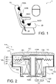
- the figure 1 illustrates, according to a schematic view, an aircraft chair, as a stimulation system 10, comprising four electromagnetic transducers 100A, 100B, 100C, 100D housed in a trim 30 of the aircraft chair, said chair being installed in an aircraft 1.
- the stimulation system 10 is an aircraft seat
- the invention is of course not limited to this sole application and relates to any type of stimulation system 10 intended to transmit vibratory stimuli and which is likely to include such electromagnetic transducers 100A, 100B, 100C, 100D.
- the stimulation system 10 can also be a chair of a motorized land or sea vehicle, an office chair or even a bed or a massage table, equipped with said electromagnetic transducers to supply, to the means of transmitting vibratory stimuli provided by the electromagnetic transducers, a massage or a sensory signal to the user of said stimulation system, without departing from the scope of the invention.
- transducers are aimed in particular at the admission of massage to users of said stimulation systems 10, other applications are perfectly possible, without departing from the scope of the invention.
- such transducers can be used in the context of user entertainment, such as as video game activities or consumption of multimedia content, the transducers being able to apply infrasound or low frequency stimulation in connection with said activities.
- such transducers can be used to transmit information to the user of said stimulation system 10, such as, for example and in the context of an application to a pilot's chair aircraft, force feedback concerning pilot commands or flight information.
- Such a stimulation system 10 can be a wall or a floor, including in their lining 30 (that is to say their internal material of said wall or floor), an electromagnetic transducer 100A, 100B, 100C, 100D to transmit a vibratory stimulus to the user when he comes into contact with a part of said wall or floor equipped with said electromagnetic transducer 100A, 100B, 100C, 100D.
- FIG 1 shows, in addition to the four electromagnetic transducers 100A, 100B, 100C, 100D which are integrated into the upholstery 30 of the chair, a control unit 20 of said transducers capable of supplying a control signal to said electromagnetic transducers 100A, 100B, 100C.
- a control unit 20 of said transducers capable of supplying a control signal to said electromagnetic transducers 100A, 100B, 100C.
- Such a configuration of the control unit 20 is of course only an example, other configurations are perfectly possible without departing from the scope of the invention, the control unit 20 being able for example to be integrated into a centralized control unit of a vehicle or even provided in two parts, a respective sub-unit integrated into each electromagnetic transducer 100A, 100B, 100C, 100D and a central unit connected to said control sub-unit.
- electromagnetic transducers 100A, 100B, 100C, 100D illustrated in the figure 1 is given by way of example only and is in no way limiting.
- the chair comprises a number of four electromagnetic transducers 100A, 100B, 100C, 100D with a distribution along the backrest and the seat, it is perfectly possible to distribute them differently.
- transducers electromagnetic 100A, 100B, 100C, 100D can be arranged in pairs distributed on either side of an axis of symmetry of the armchair with a similar distribution along the backrest and the seat (that is to say a configuration with 8 electromagnetic transducers), or a large electromagnetic transducer 100A, 100B, 100C, 100D for the seat and 6 smaller electromagnetic transducers 100A, 100B, 100C, 100D for the backrest.
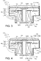
- the electromagnet 141 is secured to the movable element 120 and the first magnet 125 is secured to the housing 110.
- the housing 110 comprises a cover 115 having the bearing face 111 and a body 117 closed by said cover 115, the cover 115 being integral with the body 117.
- the body 117 has a main housing 118, delimited in part by the cover 115 and a secondary housing 119, opposite the cover 115.
- the main housing 118 and the secondary housing 119 each have a cylindrical shape of revolution and are in communication with each other at an open common base which is, for the main housing, opposite the cover 115.
- another shape of the body 117 is perfectly possible without departing from the scope of the invention.
- the body 117 and the cover 115 are made of a ferromagnetic material.
- the body can comprise openings 116, or vents, on a face opposite the cover.
- openings 116 allow fluid communication between the secondary housing 119 and the exterior of the body and thus allow the evacuation of part of the thermal energy generated by the electromagnet 141 during the operation of the electromagnetic transducer 100.
- the openings 116 can be chosen with a reduced size or with a metal mesh in order to provide electromagnetic shielding and thus avoid an emission outside the box 110 of any electromagnetic disturbances that the electromagnetic actuation system 140 could generate.
- the body 117 and the cover 115 can both be made of electrically conductive materials.
- the electromagnet 141 is referenced only by its coil, the core 121 being described independently of the rest of the electromagnet 141.
- the core 121 has the shape of a hollow cylinder of revolution with an open base that can also be defined as tubular, the bases of said cylinder having radial extensions so as to define along its side wall a housing for the coil of the electro -magnet 141.
- the core 121 can be in two parts, an outer cylinder 121A, having the radial extensions, and an inner cylinder 121B inscribed inside the outer cylinder.
- the outer cylinders and interior 121A, 121B of the core are electrically insulated from each other by means, for example, of a layer of dielectric material placed between them.
- the holding between the outer cylinder 121A and the inner cylinder 121B is achieved by crimping at the base of the inner cylinder 121B.
- Other holding systems, such as force fitting, can also be envisaged without departing from the scope of the invention.
- the core 121 can comprise a winding of at least one sheet of ferrous material, two successive windings being separated from each other by a dielectric material.
- a winding can, for example, be formed by winding a single sheet of ferrous material coated with the dielectric material such as a varnish.
- at least one of the outer cylinder 121A and of the inner cylinder 121B can comprise such a winding.
- the movable element 120 comprises only the coil of the electromagnet 141 and the core 121
- the mobile element 120 comprises an insert made of non-magnetic material, this insert being inserted into the core in order to increase the mass of the mobile element 120.
- the movable element, and therefore the electromagnet 141 is free of core 121.
- thermosensitive element 142 is, in the present embodiment, associated with the electromagnet 141 by being positioned between the coil of the electromagnet 141 and the core 121 or only in the coil to prevent excessive heating of the wire of the electromagnet coil. Such an association allows the thermosensitive element 142 to be subjected to the temperature variations of the electromagnet 141. Of course, other arrangement/association between the thermosensitive element 142 and the electromagnet 141 are possible. without departing from the scope of the invention.
- thermosensitive element 142 is a remote temperature sensor, such as an infrared temperature sensor
- the thermosensitive element 142 can be arranged on the wall of the case 110 facing the electromagnet 141 so as to allow a measurement of the temperature of the electromagnet 141.
- the thermosensitive element 142 can be a temperature sensor connected to the control unit 20 and associated with a threshold temperature from which the control unit reduces, or even eliminates, the supply of the electromagnet 141 and thus reduce the thermal energy released by the latter.
- the control unit 20 is configured to recover the temperature signal supplied by the heat-sensitive element and, when the signal supplied by the heat-sensitive element corresponds to a temperature greater than or equal to, or even strictly greater than, the threshold temperature , limit, or even stop, the supply of the electromagnet 141.
- the temperature sensor can be associated with two threshold temperatures, a first relatively low threshold temperature, for example, less than or equal to 50° C. or even 60° C., from which the supply of the electromagnet 141 is limited, and a second relatively high threshold temperature, for example greater than or equal to 80° C. or even 100° C., from which the power supply to the electromagnet 141 is stopped, this only resuming from limited manner, when the temperature passes a third threshold temperature intermediate to said first and second threshold temperatures.
- a first relatively low threshold temperature for example, less than or equal to 50° C. or even 60° C.
- a second relatively high threshold temperature for example greater than or equal to 80° C. or even 100° C.
- thermosensitive element 142 can be a thermo-controlled switch, preferably self-resetting, such as a self-resetting thermal fuse also known under the English name “polyswitch fuse”. According to this other possibility, the thermosensitive element 142 is arranged in series with the electromagnet in such a way that the supply of the electromagnet is stopped when the thermal fuse reaches a threshold temperature.
- the threshold temperature with which the heat-sensitive element is associated is preferably less than or equal to 100°C, or even less than or equal to 70°C or even less than or equal to 60°C.
- said threshold temperature can be selected according to the type of protection expected. Indeed, a temperature of 100°C is particularly suitable for protecting the electromagnet 141 and in particular the dielectric material used for the winding of the coil of the electromagnet 141, whereas a temperature of 60°C is more suitable when the aim is to preserve the comfort of the user as well as possible (a temperature of 100° C. is nevertheless acceptable, in particular because of the use of an interface element 113, as discussed below).
- the first magnet 145 can be arranged on one face of the cover 115, in the present embodiment , the support face 111, being integral with the latter, or on one of the faces of the housing 110 which is opposite the cover 115.
- the first magnet 145 is arranged on an outer face of the cover 115, it is also possible, without departing from the scope of the invention, that the first magnet either arranged on an internal face of said cover as described below in the context of the second embodiment and illustrated in the picture 3 .
- this face can either be an external face or an internal face of said box 110.
- the electromagnetic actuation system 140 may comprise, in addition to the first magnet 145, a second magnet 146 secured to one of a face of the cover 115 and the one of the faces of the housing 110 which is opposite the cover 115, as shown in the picture 3 , the first magnet 145 being integral with one other of a face of the cover 115 and one of the faces of the housing 110 which is opposite the cover 115.
- the movable element 120 is housed partly in the main housing 118 and partly in the secondary housing 119.
- the secondary housing 119 can be equipped with guide elements 147, such as a sliding bearing, along which a part of the mobile element 120, here a radial extension of the core 121 slides during the movement in translation of the movable element 120.
- guide elements 147 such as a sliding bearing, along which a part of the mobile element 120, here a radial extension of the core 121 slides during the movement in translation of the movable element 120.
- Such sliding bearings can be provided by a polyamide, such as a Nylon, or by a Polyoxymethylene, also known by the acronym POM.
- the movable element 120 is connected to the walls of the main housing 118 by means of the first elastic return element 130.
- the first elastic return element 130 comprises at least one thermal insulating material in order to limit the transmission of thermal energy from the element mobile 120 (to be more precise of the electromagnet 141) towards the housing 110.
- This same insulating material is also preferentially non-magnetic, in order to avoid any interference with the electromagnetic actuation system 140 and more precisely not to short-circuit the core magnetic flux between electromagnet 141 and first magnet 145 which produces the attraction-repulsion effect.
- the first elastic return element 130 can, for example, comprise a resin, such as a poly(methyl methacrylate) resin, alone or impregnating a fibrous support or fabric.
- a resin such as a poly(methyl methacrylate) resin
- the casing 110 may comprise at least one damper 122A, 122B arranged to interpose itself between the casing and the movable element during a possible extreme displacement.
- the housing 110 may comprise a first and a second damper 122A, 122B, the first damper 122A on an internal face cover 115 facing the movable element 120, and the second damper 122B, on an internal face of the body 117 at the opposite the inner face of the cover 115.
- the damper 122A, 122B can comprise an elastomer, such as a silicone or a rubber (natural or synthetic).
- the mobile element 120, the first elastic return element 130 and the damper(s) 122A, 122B can be configured so that the mobile element 120 has a resonance frequency of between 1 and 100 Hz, or even between 5 and 50 Hz and preferably between 10 and 30 Hz.
- the housing 110 may comprise, as illustrated in the picture 2 , at the support face 111, the interface element 113 comprising at least one elastomer, said interface element 113 being intended to come into abutment, through a possible covering, of the user for him transmit the movement of the mobile element 120.
- the interface element can comprise a plurality of cavities. Such cavities make it possible to give the interface element cushioning and additional thermal insulation with respect to an interface element devoid of such cavities.
- the electromagnetic transducer can comprise a displacement sensor 143 arranged in the casing and configured to provide a signal relating to the movement of the case.
- the displacement sensor can thus be selected from the group comprising accelerometers, gyrometers and gyroscopes.
- the displacement sensor 151 can be, for example, arranged integral with the cover 115 or, according to a possibility not illustrated, integral with the body 117.
- the control unit 20 is able to determine information concerning the electromagnetic transducer 100 and the stimulation system 10, such as the orientation of the stimulation system 10, the installation of a new user on said stimulation system 10, an estimate of the diverence of said user, and thus adapt the world of operation of the or each electromagnetic transducer according to the determined information.
- This same information can also be used to adjust certain environmental parameters of the stimulation system. 10, such as the orientation of one or more lights, airflow, or equipment such as a screen.
- the displacement sensor 151 and the thermosensitive element 142 are both connected to a connector 152 passing through the housing 110 in order to allow the connection to the control unit 20.
- This same connector 152 is also used to connect the electromagnet 141 to the control unit in order to authorize its supply by the latter.
- the picture 3 illustrates an electromagnetic transducer 100 according to a second embodiment in which cover 115 comprises at least one movable part 115A vis-à-vis the body 117, such that the displacement of the movable element 120 drives said movable part 115A of the cover 115 on the go.
- An electromagnetic transducer 100 according to this second embodiment differs from an electromagnetic transducer 100 according to the first embodiment in that the cover 115 is movable with respect to the body 117 of the housing 110, in that the first magnet 145 is arranged on an internal face of the cover 115 housed in the damper 122B and in that a second magnet 146 is provided arranged on an internal face of the body 117 housed in the damper 122A.
- the cover 115 is arranged to move in translation relative to the body 117 of the housing 110, in such a way that the movement of the mobile element causes the cover 115 to move.
- the body may comprise, as illustrated in the picture 3 , stops, able to delimit the amplitude of movement of the cover 115 vis-à-vis the body 117.
- the cover 115 can be shaped in such a way as to have a resonance frequency of between 50 and 150 Hz, preferably between 75 and 125 Hz. In this way, by having a resonance frequency distinct from that of the mobile element 120, in correspondence or not to a harmonic of the resonance frequency of the mobile element 120, the electromagnetic transducer 100 is able to provide a vibratory stimulus over a larger frequency range and thus facilitate the relaxation of the user.
- the figure 4 illustrates an electromagnetic transducer 100 according to a third embodiment in which cover 115 comprises a second elastic return element 115B connecting mobile part 115A of cover 115 to body 117.
- An electromagnetic transducer 100 according to a third embodiment differs from an electromagnetic transducer 100 according to the first embodiment in that it comprises the second elastic return element 115B and in that a mobile part 115A of the cover moves vis -à-vis the body 117 by deformation of said second elastic return element 115B.
- the second elastic return element 115B and the movable part 115B can be provided in the form of two separate parts from each other, one constituting the second elastic return element and the movable part forming the cover as such.
- the second elastic element comprises a ferromagnetic material, such as for example a filler of ferrous material from a resin, in order to ensure magnetic continuity between the body 117 and the movable part 115B of the cover 115.
- the cover 115 can be formed in one piece having a variable thickness or a suitable shape with a central part, forming the mobile part 115A, and a peripheral part 115B, shaped by its thickness or its shape, to form the second elastic return element, by which the cover 115 is connected to the body 111.
- the peripheral part 115B can have a relatively reduced thickness and/or a specific shape with respect to the mobile part 115A .
- the peripheral part has sufficient elasticity to form the second elastic return element 115B and the movable part 115A has, due to its relatively high thickness, sufficient rigidity to transmit a movement to the user.
Landscapes
- Engineering & Computer Science (AREA)
- Health & Medical Sciences (AREA)
- Aviation & Aerospace Engineering (AREA)
- Rehabilitation Therapy (AREA)
- Animal Behavior & Ethology (AREA)
- Epidemiology (AREA)
- Pain & Pain Management (AREA)
- Physical Education & Sports Medicine (AREA)
- Veterinary Medicine (AREA)
- Life Sciences & Earth Sciences (AREA)
- Public Health (AREA)
- General Health & Medical Sciences (AREA)
- Mechanical Engineering (AREA)
- Transportation (AREA)
- Percussion Or Vibration Massage (AREA)
- Apparatuses For Generation Of Mechanical Vibrations (AREA)
- Reciprocating, Oscillating Or Vibrating Motors (AREA)
Abstract
Description
- L'invention concerne le domaine des systèmes de stimulation destinés à la transmission de stimuli vibratoires à des utilisateurs, tels que par exemple des fauteuils massant et/ou de multimédia.
- L'invention a plus précisément pour objet un transducteur électromagnétique, un système de stimulation comprenant un tel transducteur électromagnétique, et un véhicule intégrant un tel système de stimulation.
- Il est connu d'équiper des systèmes de stimulation tactile/vibratoire, tels que des fauteuils massant et/ou de multimédia, par des transducteurs électromagnétiques afin de transmettre aux utilisateurs desdits systèmes de stimulation des stimuli vibratoires contribuant à un acte de massage ou à des transmissions sensitives en lien avec un média consommé par l'utilisateur ou informatif.
- Par stimulus vibratoire, on entend ici et dans le reste de cette demande la transmission d'un mouvement/vibration à l'utilisateur, ce mouvement/vibration présentant préférentiellement une fréquence dans l'infrason et/ou les basses fréquences dites profondes. Ainsi un tel stimulus vibratoire peut avoir une fréquence comprise entre 1 Hz et 100 Hz, voire entre 5 Hz et 50 Hz.
- Ces transducteurs électromagnétiques comprennent généralement un boîtier dans lequel est montée une masselotte, montée mobile en translation dans ledit boîtier, et un système d'électro-aimant pour déplacer la masselotte. Néanmoins, compte tenu de la masse relativement importante d'une telle masselotte, le courant nécessaire pour la déplacer est relativement important et l'électro-aimant est sujet à un échauffement important qui peut être gênant pour l'utilisateur.
- Ce problème est en partie résolu, comme cela est notamment montré dans le document
US 4354067 , par un couplage thermique de la bobine de l'électro-aimant avec le boîtier et en prévoyant un boîtier au moins en partie dans un matériau conducteur thermique. De cette manière, l'énergie thermique générée lors de l'alimentation en courant de l'électro-aimant peut être au moins en partie dissipée par le boîtier en matériau conducteur thermique. - Néanmoins, si une telle solution permet de limiter l'élévation de température du transducteur électromagnétique, elle n'est pas totalement satisfaisante, puisque la dissipation thermique est obtenue par le boîtier. De ce fait, la chaleur dissipée par le boîtier se fait en partie au contact de l'utilisateur qui reste donc soumis à un échauffement relativement important malgré l'optimisation de la dissipation thermique. Ainsi, il n'existe pas, à l'heure actuelle, de transducteur électromagnétique pour un système de stimulation, tel qu'un dispositif de massage, qui soit exempt d'un tel problème de soumission de l'utilisateur à la chaleur dégagée par l'électro-aimant lors de son activation tout en assurant une fiabilité accrue du transducteur électromagnétique.
- Ainsi, l'invention a pour objet de résoudre le problème ci-dessus et vise la fourniture d'un transducteur électromagnétique autorisant la fourniture d'une protection de l'utilisateur vis-à-vis de la chaleur émise par l'électro-aimant, et en particulier sa bobine, et de même qu'une protection thermique du transducteur électromagnétique pendant son activation assurant ainsi une fiabilité accrue du transducteur électromagnétique.
- L'invention concerne à cet effet, un transducteur électromécanique pour transmettre un stimulus vibratoire à un utilisateur, le transducteur électromécanique étant destiné à être logé dans une garniture d'un système de stimulation avec une face d'appui affleurant ladite garniture pour transmettre le stimulus à un utilisateur dudit système de stimulation, le transducteur électromécanique comprenant :
- un boîtier présentant la face d'appui,
- un élément mobile monté mobile en translation dans le boîtier au moyen d'au moins un premier élément de rappel élastique,
- un système d'actionnement électromagnétique, configuré pour mettre en mouvement l'élément mobile, le système d'actionnement comprenant un électro-aimant et au moins un premier aimant.
- L'électro-aimant est solidaire de l'élément mobile et l'aimant est solidaire du boîtier.
- Le premier élément de rappel élastique comprend un matériau isolant thermique, et le transducteur électromécanique comprend en outre un élément thermosensible associé à l'électro-aimant.
- Avec une telle configuration, l'électro-aimant étant solidaire de l'élément mobile et l'élément mobile étant lui-même isolé thermiquement du boîtier par le premier élément de rappel élastique, la chaleur évacuée vers l'utilisateur est ainsi réduite.
- De plus, le fait de prévoir un élément thermosensible associé à l'électro-aimant autorise à la fois une protection de l'utilisateur et un bon fonctionnement du transducteur. En effet, un tel élément thermosensible autorise une limitation, voire une coupure, du courant transmis à l'électro-aimant en cas d'échauffement de l'électro-aimant dont pourrait résulter une élévation en température du boîtier potentiellement gênante pour l'utilisateur ou engendrer un disfonctionnement du transducteur.
- Ainsi avec une telle combinaison d'isolation thermique et de protection thermique autorisée par l'élément thermosensible, il est possible de protéger l'utilisateur de la gêne que pourrait engendrer la chaleur émise par l'électro-aimant du transducteur électromagnétique pendant son activation.
- On notera, de plus, avec une telle configuration dans laquelle l'électroaimant est solidaire de l'élément mobile, on évite les risques d'endommagement de l'électroaimant par l'élément mobile lors de ses déplacements. Il en résulte donc une fiabilité accrue vis-à-vis des transducteurs électromagnétiques de l'art antérieur pour lesquels l'électroaimant est agencé solidaire au boîtier et qui présente, de ce fait, un risque d'endommagement lors des déplacements de l'élément mobile.
- Par garniture du système de stimulation il doit être entendu ci-dessus et dans le reste de ce document le matériau constituant au moins une partie interne du système de stimulation, telle qu'une mousse d'un fauteuil ou d'une table de massage, lorsque de le système de stimulation est un fauteuil ou une table de massage, le matériau constituant un mur, lorsque de le système de stimulation est un mur équipé de transducteurs selon l'invention. Bien entendu, une telle garniture peut être ou non associée à un habillage, tel qu'un tissu ou un habillage de cuir d'un fauteuil, ou encore un papier peint d'un mur.
- On entend ci-dessus et dans le reste de ce document par « isolant thermique », un matériau présentant une conductivité thermique inférieure à 1 W.m-1.K-1.
- Le boîtier peut comprendre un capot présentant la face d'appui et un corps fermé par ledit capot, l'élément mobile étant monté mobile vis-à-vis du corps.
- Le capot peut comprendre au moins une partie mobile vis-à-vis du corps.
- La partie mobile du capot peut être reliée au corps au moyen d'un deuxième élément de rappel élastique, l'ensemble partie mobile du capot et deuxième élément de rappel élastique présentant une fréquence de résonnance supérieure à une fréquence de résonnance de l'ensemble élément mobile et premier élément de rappel élastique.
- On notera qu'un tel deuxième élément de rappel élastique peut être fourni par une partie périphérique du capot qui est amincie ou/et spécialement formée vis-à-vis de la partie mobile qui est centrale.
- En variante à cette possibilité, le deuxième élément de rappel élastique peut être un élément distinct de la partie mobile.
- Dans une telle configuration, le capot est à même de se déplacer en étant entrainé par le déplacement de l'élément mobile et/ou le les variations de flux magnétique générées par l'électroaimant.
- Ainsi, un tel deuxième élément de rappel élastique permet à l'élément mobile et la partie mobile du capot de présenter des fréquences de résonnance différentes permettant ainsi au transducteur de présenter une bande passante plus importante quant à la fréquence de mouvement transmissible à l'utilisateur
- Avec une l'une ou l'autre de ces configurations, le capot est apte à participer à la transmission du mouvement de l'élément mobile afin de produire un stimulus vibratoire pouvant être utilisé selon les cas d'usage cités en préambule.
- Le transducteur électromécanique peut comprendre en outre un capteur de déplacement agencé dans le boîtier et configuré pour fournir un signal relatif au déplacement dudit boîtier.
- Un tel capteur de déplacement permet de fournir des informations concernant à la fois l'orientation du boîtier et l'amplitude du mouvement transmis à l'utilisateur. Ces informations peuvent ensuite être utilisées pour optimiser la simulation d'acte de massage appliqué à l'utilisateur.
- Un tel capteur de déplacement peut être un capteur de déplacement en tant que tel, tel qu'un capteur capacitif ou un capteur permettant d'indexer un déplacement, un capteur de changement d'orientation, tel qu'un gyromètre ou un gyroscope, ou encore un accéléromètre, voire une combinaison de plusieurs capteurs.
- Le capteur de déplacement peut être solidaire du capot.
- De cette manière, le capteur de déplacement est à même de transmettre des informations sur le mouvement du capot.
- L'élément thermosensible peut être sélectionné parmi les interrupteurs thermo-commandés, préférentiellement auto-réarmables, et les capteurs de température.
- De tels éléments thermosensibles sont particulièrement adaptés pour permettre de limiter, voire supprimer, l'alimentation de l'électro-aimant.
- L'élément thermosensible peut être associé à une température seuil à partir de laquelle l'alimentation de l'électro-aimant est limitée voire supprimée.
- L'élément mobile peut comprendre un noyau de l'électro-aimant, ledit noyau comprenant au moins une forme creuse telle qu'une forme tubulaire.
- Un tel noyau de forme creuse permet d'optimiser les performances de l'électro-aimant avec une limitation les phénomènes de courant de Foucault qui pourraient les perturber. Le noyau peut comporter un enroulement d'au moins une feuille en matériau ferreux, deux enroulements successifs étant séparés l'un de l'autre par un matériau diélectrique. Un tel enroulement est particulièrement adapté pour limiter les phénomènes de courant de Foucault.
- Le boîtier peut comporter au niveau de la face d'appui un élément d'interface comprenant au moins un élastomère, ledit élément d'interface étant destiné à venir en appui, au travers d'un éventuel habillage, de l'utilisateur pour lui transmettre le stimulus vibratoire à l'utilisateur.
- Ledit élastomère peut être un silicone ou un caoutchouc nature ou un caoutchouc synthétique.
- Un tel élément d'interface fourni une couche isolante thermiquement au niveau de la face d'appui limitant la transmission de chaleur du boîtier vers l'utilisateur. Le confort de l'utilisateur en est ainsi préservé.
- On notera, de plus, qu'un tel élément d'interface peut également limiter la transmission des fréquences sonores audibles que pourrait générer le déplacement de l'élément mobile et/ou une éventuelle partie mobile du capot.
- L'élément d'interface peut comprendre une pluralité de cavités.
- De telles cavités permettent de conférer à l'élément d'interface un amorti et une isolation thermique supplémentaire vis-à-vis d'un élément d'interface dépourvue de telles cavités. Le boîtier comportant un corps et un capot qui présente la face d'appui, le corps peut comprendre des ouvertures sur une face opposée au capot.
- De telles ouvertures, ou évents, permettent une communication fluidique entre le logement formé par le boîtier et l'extérieur du boîtier autorisant ainsi l'évacuation d'une partie de l'énergie thermique générée par l'électro-aimant.
- L'invention concerne en outre un système de stimulation destiné à fournir des stimuli vibratoires à un utilisateur comprenant une garniture et au moins un transducteur électromécanique selon l'invention, ledit au moins un transducteur étant logé dans la garniture avec une face d'appui affleurant ladite garniture.
- Un tel système de stimulation bénéficie des avantages liés au transducteur électromécanique dont il est pourvu.
- L'élément thermosensible du ou de chaque transducteur électromécanique peut être un capteur de température et le système de stimulation peut comprendre en outre au moins une unité de commande du ou des transducteurs électromécaniques configurée pour alimenter l'électro-aimant du ou des transducteurs électromécaniques, l'unité de commande étant en outre configurée pour récupérer un signal de température fourni par le ou les capteurs de température et pour, lorsqu'un ou plusieurs signaux de température fournis par le ou les capteurs de température correspondent à une température supérieure ou égale, voire strictement supérieure, à une température seuil, limiter, voire arrêter, l'alimentation du ou des électro-aimants pour lequel les signaux de température fournis par le ou les capteurs de température correspondant à une température supérieure ou égale à la température seuil.
- Une telle configuration du système de stimulation autorise une adaptation de l'alimentation de l'électro-aimant en cas de surchauffe. On évite ainsi tout risque de désagréments pour l'utilisateur même en cas de sollicitation significative du transducteur électromagnétique.
- Le système de stimulation peut-être un siège de véhicule, ledit siège étant préférentiellement un siège destiné à équiper un aéronef.
- Un tel système de stimulation bénéficie plus particulièrement des avantages de l'invention.
- L'invention concerne en outre un véhicule comprenant un système de stimulation selon l'invention.
- Un tel véhicule permet d'offrir à ces passagers les avantages liés au système de stimulation qui l'équipe.
- La présente invention sera mieux comprise à la lecture de la description d'exemples de réalisation, donnés à titre purement indicatif et nullement limitatif, en faisant référence aux dessins annexés sur lesquels :
- [
Fig.1 ] illustre un système de stimulation, ici un fauteuil de massage pour un aéronef, selon l'invention équipé de quatre transducteurs électromagnétiques selon l'invention. - [
Fig.2 ] illustre une vue en section schématique d'un transducteur électromagnétique selon un premier mode de réalisation dans lequel un capot d'un boîtier dudit transducteur est solidaire d'un corps de ce même boîtier. - [
Fig.3 ] illustre une vue en section schématique d'un transducteur électromagnétique selon un deuxième mode de réalisation dans lequel le capot du boîtier du transducteur est monté mobile en translation vis-à-vis du corps du boîtier. - [
Fig.4 ] illustre une vue en section schématique d'un transducteur électromagnétique selon un troisième mode de réalisation dans lequel le capot comprend une partie centrale mobile vis-à-vis du corps ceci au moyen au moyen d'un élément de rappel élastique. - Des parties identiques, similaires ou équivalentes des différentes figures portent les mêmes références numériques de façon à faciliter le passage d'une figure à l'autre.
- Les différentes parties représentées sur les figures ne le sont pas nécessairement selon une échelle uniforme, pour rendre les figures plus lisibles.
- Les différentes possibilités (variantes et modes de réalisation) doivent être comprises comme n'étant pas exclusives les unes des autres et pouvant se combiner entre elles.
- La
figure 1 illustre, selon une vue schématique, un fauteuil d'aéronef, en tant que système de stimulation 10, comprenant quatre transducteurs électromagnétiques 100A, 100B, 100C, 100D logés dans une garniture 30 du fauteuil d'aéronef, ledit fauteuil étant installé dans un aéronef 1. - On notera que bien entendu, si dans le présent exemple, le système de stimulation 10 est un fauteuil d'aéronef, l'invention ne se limite, bien entendu, pas à cette seule application et concerne tout type de systèmes de stimulation 10 destiné à transmettre des stimuli vibratoires et qui est susceptible de comporter de tel transducteurs électromagnétiques 100A, 100B, 100C, 100D. Ainsi, selon des possibilités non illustrées et non limitatives, le système de stimulation 10 peut également être un fauteuil de véhicule motorisé terrestre ou marin, un fauteuil de bureau ou encore un lit ou une table de massage, équipés desdits transducteurs électromagnétiques pour fournir, au moyen de la transmission de stimuli vibratoires fournis par les transducteurs électromagnétiques, un massage ou un signal sensitif à l'utilisateur dudit système de stimulation, ceci sans que l'on sorte du cadre de l'invention.
- De plus, si de tels transducteurs visent en particulier l'admission de massage à des usagers desdits systèmes de stimulation 10, d'autres applications sont parfaitement envisageables, sans que l'on sorte du cadre de l'invention. En particulier, de tels transducteurs peuvent être utilisés dans le cadre de divertissements de l'utilisateur, tels que des activités de jeux vidéo ou de consommation de contenues multimédia, les transducteurs étant à même d'appliquer des stimulations infrason ou basses fréquences en lien avec lesdites activités. Selon une autre possibilité d'application de l'invention, de tels transducteurs peuvent être utilisés pour transmettre une information à l'utilisateur dudit système de stimulation 10, telle que, par exemple et dans le cadre d'une application à un fauteuil de pilote d'aéronef, un retour de force concernant des commandes de pilotage ou des informations de vol.
- De même, si de tels systèmes de stimulation sont généralement des meubles, voire des fauteuils, d'autres types de systèmes de stimulation peuvent être envisagés sans que l'on sorte du cadre de l'invention. Ainsi un tel système de stimulation 10 peut être un mur ou un planché, incluant dans leur garniture 30 (c'est-à-dire leur matériau interne dudit mur ou planché), un transducteur électromagnétique 100A, 100B, 100C, 100D pour transmettre un stimulus vibratoire à l'utilisateur lorsqu'il rentre en contact avec une partie dudit mur ou planché équipée par ledit transducteur électromagnétique 100A, 100B, 100C, 100D.
- On notera que la
figure 1 montre, outre les quatre transducteurs électromagnétiques 100A, 100B, 100C, 100D qui sont intégrés à la garniture 30 du fauteuil, une unité de commande 20 desdits transducteurs apte à fournir un signal de commande auxdits transducteurs électromagnétiques 100A, 100B, 100C. Une telle configuration de l'unité de commande 20 est bien entendu qu'un exemple, d'autres configurations sont parfaitement envisageables sans que l'on sorte du cadre de l'invention, l'unité de commande 20 pouvant par exemple être intégrée à une unité de commande centralisée d'un véhicule ou encore fournie en deux partie, une sous-unité respective intégrée à chaque transducteur électromagnétique 100A, 100B, 100C, 100D et une unité centrale connectée auxdites sous-unité de commande. - De même la configuration de transducteurs électromagnétiques 100A, 100B, 100C, 100D illustrée sur la
figure 1 est donnée qu'à titre d'exemple et n'est nullement limitative. Ainsi, si le fauteuil comprend un nombre de quatre transducteurs électromagnétiques 100A, 100B, 100C, 100Davec une répartition le long du dossier et de l'assise, il est parfaitement envisageable de les répartir autrement. Par exemple, les transducteurs électromagnétiques 100A, 100B, 100C, 100D peuvent être agencés par paires réparties de part et d'autre d'un axe de symétrie du fauteuil avec une répartition similaire le long du dossier et de l'assise (c'est-à-dire une configuration à 8 transducteurs électromagnétiques), ou encore un transducteur électromagnétique 100A, 100B, 100C, 100D de grande taille pour l'assise et 6 transducteurs électromagnétiques 100A, 100B, 100C, 100D de plus petite taille pour le dossier. - Dans le cadre d'un premier mode de réalisation et comme illustré sur la
figure 2 , le transducteur électromagnétique 100 comprend : - un boîtier 110 présentant la face d'appui 111,
- un élément mobile 120 logé dans le boîtier 110 et monté dans le boîtier 110 mobile en translation au moyen d'au moins un premier élément de rappel élastique 130 réalisé dans un matériau isolant thermique, et,
- un système d'actionnement électromagnétique 140, configuré pour mettre en mouvement l'élément mobile, le système d'actionnement comprenant un électro-aimant 141 et un premier aimant 145, l'électro-aimant 141 incluant un élément thermosensible 142.
- Conformément à l'invention, l'électro-aimant 141 est solidaire de l'élément mobile 120 et le premier aimant 125 est solidaire du boîtier 110.
- Dans le présent mode de réalisation, le boîtier 110 comprend un capot 115 présentant la face d'appui 111 et un corps 117 fermé par ledit capot 115, le capot 115 étant solidaire du corps 117.
- Le corps 117 présente un logement principal 118, délimité en partie par le capot 115 et un logement secondaire 119, à l'opposé du capot 115. Conformément à la
figure 2 , le logement principal 118 et Le logement secondaire 119 présentent chacun une forme cylindrique de révolution et sont en communication l'un avec l'autre au niveau d'une base commune ouverte qui est, pour le logement principal, à l'opposé du capot 115. Bien entendu, d'autre forme du corps 117 est parfaitement envisageable sans que l'on sorte du cadre de l'invention. - De manière préférentielle, le corps 117 et le capot 115 sont réalisés dans un matériau ferromagnétique.
- Selon une possibilité de l'invention, reprise dans le présent mode de réalisation, le corps peut comprendre des ouvertures 116, ou évents, sur une face opposée au capot. De telles ouvertures 116 permettent une communication fluidique entre le logement secondaire 119 et l'extérieur du corps et autorisent ainsi l'évacuation d'une partie de l'énergie thermique générée par l'électro-aimant 141 lors du fonctionnement du transducteur électromagnétique 100.
- On notera, que dans le cadre d'une application de l'invention dans laquelle le système de stimulation 10 équipe un aéronef, les ouvertures 116 peuvent être choisies avec une taille réduite ou avec un maillage métallique afin de fournir un blindage électromagnétique et ainsi éviter une émission en dehors du boîtier 110 des éventuelles perturbations électromagnétiques que le système d'actionnement électromagnétique 140 pourrait générer. En conformité avec une telle application, le corps 117 et le capot 115 peuvent être tout deux réalisés dans des matériaux conducteurs électriques.
- Dans le cadre du ce premier mode réalisation, l'élément mobile 120 comprend :
- l'électro-aimant 141, comprenant une bobine en matériau conducteur électrique, tel que du cuivre, et incluant l'élément thermosensible 142, et
- un noyau 121 en matériau ferromagnétique de l'électro-aimant 141.
- Ainsi, dans la présente divulgation, par simplification et abus de langage, l'électro-aimant 141 est référencé uniquement par sa bobine, le noyau 121 étant décrit de manière indépendante du reste de l'électro-aimant 141.
- Comme montré sur la
figure 1 , le noyau 121 présente une forme de cylindre de révolution creux et à base ouverte pouvant également être définie comme tubulaire, les bases dudit cylindre présentant des extensions radiales de manière à définir le long de sa paroi latérale un logement pour la bobine de l'électro-aimant 141. - Selon une possibilité de l'invention, conforme au présent mode de réalisation, le noyau 121 peut se présenter en deux parties, un cylindre extérieur 121A, présentant les extensions radiales et, un cylindre intérieur 121B inscrit à l'intérieur du cylindre extérieur. Selon cette possibilité et afin de limiter les courants de Foucaults, les cylindres extérieur et intérieur 121A, 121B du noyau sont isolés électriquement l'un de l'autre au moyen, par exemple, d'une couche de matériau diélectrique disposée entre eux. On notera que dans l'exemple de réalisation de ce premier mode de réalisation, le maintien entre le un cylindre extérieur 121A et le cylindre intérieur 121B est réalisé par un sertissage au niveau de la base du cylindre intérieur 121B. D'autres systèmes de maintien, tel qu'un montage en force, sont également envisageables sans que l'on sorte du cadre de l'invention.
- En variante et selon une configuration avantageuse non illustrée, le noyau 121 peut comprendre un enroulement d'au moins une feuille en matériau ferreux, deux enroulements successifs étant séparés l'un de l'autre par un matériau diélectrique. Un tel enroulement peut, par exemple, être formé par l'enroulement d'une seule feuille en matériau ferreux revêtue du matériau diélectrique tel qu'un vernis. Selon cette même variante, en conformité à la possibilité de ce premier mode de réalisation selon laquelle le noyau 121 peut être en deux parties, au moins l'un du cylindre extérieur 121A et du cylindre intérieur 121B peut comprendre un tel enroulement.
- On notera également que, si dans le présent mode de réalisation, l'élément mobile 120 comprend uniquement la bobine de l'électro-aimant 141 et le noyau 121, il est également envisageable, sans que l'on sorte du cadre de l'invention que l'élément mobile 120 comprend un insert en matériau amagnétique, cet insert venant s'insérer dans le noyau afin d'augmenter la masse de l'élément mobile 120. De la même façon, il est envisageable sans que l'on sorte du cadre de l'invention, que l'élément mobile, et donc l'électro-aimant 141, soit exempt de noyau 121.
- L'élément thermosensible 142 est, dans le présent mode de réalisation, associé à l'électro-aimant 141 en étant positionné entre la bobine de l'électro-aimant 141 et le noyau 121ou seulement dans la bobine pour prévenir un échauffement excessif du fil de la bobine de l'électro-aimant. Une telle association permet à l'élément thermosensible 142 d'être soumis aux variations de température de l'électro-aimant 141. Bien entendu, d'autre agencement/ association entre l'élément thermosensible 142 et l'électro-aimant 141 sont envisageables sans que l'on sorte du cadre de l'invention. Ainsi, par exemple, dans le cas où l'élément thermosensible 142 est un capteur de température à distance, tel qu'un capteur de température par infrarouge, l'élément thermosensible 142 peut être agencé sur la paroi du boîtier 110 en regard de l'électro-aimant 141 de manière à permette une mesure de la température de l'électro-aimant 141.
- Selon une possibilité de l'invention reprise dans le présent mode de réalisation, l'élément thermosensible 142 peut être un capteur de température relié à l'unité de commande 20 et associé à une température seuil à partir duquel l'unité de commande réduit, voire supprime, l'alimentation de l'électro-aimant 141 et ainsi en réduire l'énergie thermique dégagé par ce dernier. Ainsi, l'unité de commande 20 est configurée pour récupérer le signal de température fourni par l'élément thermosensible et pour, lorsque le signal fourni par l'élément thermosensible correspond à une température supérieure ou égale, voire strictement supérieure, à la température seuil, limiter, voire arrêter, l'alimentation de l'électro-aimant 141.
- Selon cette même possibilité, le capteur de température peut être associé à deux température seuil, une première température seuil relativement basse, par exemple, inférieur ou égale à 50°C voire 60°C, à partir de laquelle l'alimentation de l'électroaimant 141 est limitée, et une deuxième température seuil relativement haute, par exemple supérieure ou égale à 80°C voire à 100°C, à partir de laquelle l'alimentation de l'électroaimant 141 est arrêtée, celle-ci ne reprenant, que de manière limité, lorsque la température passe une troisième température seuil intermédiaire auxdits première et deuxième températures seuil.
- Selon une autre possibilité, non illustrée, l'élément thermosensible 142 peut être un interrupteur thermo-commandé, préférentiellement auto-réarmable, tel qu'un fusible thermique auto-réarmable également connu sous la dénomination anglaise « polyswitch fuse ». Selon cette autre possibilité, l'élément thermosensible 142 est agencé en série avec l'électro-aimant de telle manière que l'alimentation de l'électro-aimant soit stoppée lorsque le fusible thermique atteint une température seuil.
- Quelle que soit la configuration de l'élément thermosensible 142 sélectionnée, la température seuil à laquelle est associé l'élément thermosensible est préférentiellement inférieure ou égale à 100°C, voire inférieure ou égale à 70°C ou encore inférieure ou égale à 60°C.
- On notera que ladite température seuil peut être sélectionnée en fonction du type de protection attendu. En effet, une température de 100°C est particulièrement adaptée pour une protection de l'électroaimant 141 et notamment du matériau diélectrique utilisé pour le bobinage de la bobine de l'électroaimant 141 alors qu'une température de 60°C est plus adaptée lorsque l'on cherche à préserver au mieux le confort de l'utilisateur (une température de 100°C est néanmoins acceptable notamment en raison de l'utilisation d'un élément d'interface 113, tel que cela est discuté ci-après).
- Afin de permettre la mise en déplacement de l'électro-aimant 141 et donc de l'élément mobile vis-à-vis du boîtier 110, le premier aimant 145 peut être agencé sur une face du capot 115, dans le présent mode de réalisation, la face d'appui 111, en étant solidaire de ce dernier, ou sur l'une des faces du boîtier 110 qui est opposée au capot 115.
- On notera, que bien entendu, si dans le présent mode de réalisation, le premier aimant 145 est agencé sur une face externe du capot 115, il est également envisageable, sans que l'on sorte du cadre de l'invention que le premier aimant soit agencé sur une face interne dudit capot comme cela est décrit ci-après dans le cadre du deuxième mode de réalisation et illustré sur la
figure 3 . De même, lorsque l'aimant est agencé sur l'une des faces du boitier 110, opposée au capot, cette face peut aussi bien être une face externe qu'une face interne dudit boîtier 110. - Selon une autre variante qui sera également décrite dans le cadre du deuxième mode de réalisation, le système d'actionnement électromagnétique 140 peut comporter, outre le premier aimant 145, un deuxième aimant 146 solidaire de l'un parmi une face du capot 115 et l'une des faces du boîtier 110 qui est opposée au capot 115, comme cela est montré sur la
figure 3 , le premier aimant 145 étant solidaire d'un autre parmi une face du capot 115 et l'une des faces du boîtier 110 qui est opposée au capot 115. Avec une telle variante, on obtient une efficacité renforcée du système d'actionnement électromagnétique 140 et il est possible d'utiliser des premiers et deuxièmes aimants 145, 146 avec un dimensionnement réduit. - Comme montré sur la
figure 2 , l'élément mobile 120 est logé pour partie dans le logement principal 118 et pour partie dans le logement secondaire 119. - Afin de guider l'élément mobile 120 pendant sa translation, le logement secondaire 119 peut être équipé d'éléments de guidage 147, tel qu'un palier glissant, le long duquel une partie de l'élément mobile 120, ici une extension radiale du noyau 121 coulisse pendant le déplacement en translation de l'élément mobile 120. De tels paliers glissant peuvent être fournis par un polyamide, tel qu'un Nylon, ou par un Polyoxyméthylène, également connu sous le sigle POM.
- L'élément mobile 120 est relié aux parois du logement principal 118 au moyen du premier élément de rappel élastique 130. Le premier élément de rappel élastique 130 comprend au moins un matériau isolant thermique afin de limiter la transmission d'énergie thermique de l'élément mobile 120 (pour être plus précis de l'électro-aimant 141) vers le boîtier 110. Ce même matériau isolant est également préférentiellement amagnétique, afin d'éviter toute interférence avec le système d'actionnement électromagnétique140et plus précisément ne pas court-circuiter le flux magnétique du noyau entre électro-aimant 141 et le premier aimant 145qui produit l'effet d'attraction-répulsion.
- Ainsi, le premier élément de rappel élastique 130 peut, par exemple, comprendre une résine, tel qu'une résine de poly(méthacrylate de méthyle), seule ou imprégnant un support fibreux ou tissu.
- Conformément au présent mode de réalisation, le boîtier 110 peut comprendre au moins un amortisseur 122A, 122B disposé pour s'interposer entre le boîtier et l'élément mobile lors d'un éventuel déplacement extrémal. Ainsi, comme illustré sur la
figure 2 , le boîtier 110 peut comprendre un premier et un deuxième amortisseur 122A, 122B, le premier amortisseur 122A sur une face interne capot 115 en regard de l'élément mobile 120, et le deuxième amortisseur 122B, sur une face interne du corps 117 à l'opposé de la face interne du capot 115. - Ainsi, l'amortisseur 122A, 122B peut comprendre un élastomère, tel qu'un silicone ou un caoutchouc (naturel ou synthétique).
- L'élément mobile 120, le premier élément de rappel élastique 130 et le ou les amortisseurs 122A, 122B peuvent être configurés pour que l'élément mobile 120 présente une fréquence de résonnance comprise entre 1 et 100 Hz, voire entre 5 et 50 Hz et préférentiellement entre 10 et 30 Hz.
- Afin de fournir une isolation thermique supplémentaire, le boîtier 110 peut comporter, comme illustré sur la
figure 2 , au niveau de la face d'appui 111 l'élément d'interface 113 comprenant au moins un élastomère, ledit élément d'interface 113 étant destiné à venir en appui, au travers d'un éventuel habillage, de l'utilisateur pour lui transmettre le mouvement de l'élément mobile 120. - Selon une possibilité non illustrée, l'élément d'interface peut comprendre une pluralité de cavités. De telles cavités permettent de conférer à l'élément d'interface un amorti et une isolation thermique supplémentaire vis-à-vis d'un élément d'interface dépourvu de telles cavités.
- On notera également, qu'afin de déterminer l'orientation du transducteur électromagnétique 100 et/ou déterminer l'intensité des déplacements de l'élément mobile, le transducteur électromagnétique peut comprendre un capteur de déplacement 143 agencé dans le boîtier et configuré pour fournir un signal relatif au déplacement du boîtier. Le capteur de déplacement peut ainsi être sélectionné dans le groupe comprenant les accéléromètres, les gyromètres et les gyroscopes.
- Comme illustré sur la
figure 1 le capteur de déplacement 151 peut être, par exemple, agencé solidaire du capot 115 ou encore, selon une possibilité non illustrée, solidaire au corps 117. - Avec un tel équipement du transducteur électromagnétique 100, l'unité de commande 20 est à même de déterminer des informations concernant le transducteur électromagnétique 100 et le système de stimulation 10, telles que l'orientation du système de stimulation 10, l'installation d'un nouvel utilisateur sur ledit système de stimulation 10, une estimation de la corpulence dudit utilisateur, et ainsi adapter le monde de fonctionnement du ou de chaque transducteurs électromagnétiques en fonction des informations déterminées. Ces mêmes informations peuvent également être utilisées afin de régler certains paramètres environnementaux du système de stimulation 10, tels que l'orientation d'une ou plusieurs lumières, d'un flux d'air ou d'un équipement tel qu'un écran.
- Dans le présent mode de réalisation, le capteur de déplacement 151 et l'élément thermosensible 142 sont tous deux reliés à un connecteur 152 traversant le boîtier 110 afin de permettre la connexion à l'unité de commande 20. Ce même connecteur 152 est également utilisé pour connecter l'électro-aimant 141 à l'unité de commande afin d'autoriser son alimentation par cette dernière.
- La
figure 3 illustre un transducteur électromagnétique 100 selon un deuxième mode de réalisation dans lequel capot 115 comprend au moins une partie mobile 115A vis-à-vis du corps 117, de telle manière que le déplacement de l'élément mobile 120 entraîne ladite partie mobile 115A du capot 115 en déplacement. - Un transducteur électromagnétique 100 selon ce deuxième mode de réalisation se différencie d'un transducteur électromagnétique 100 selon le premier mode en ce que le capot 115 est mobile vis-à-vis du corps 117 du boîtier 110,en ce que le premier aimant 145 est agencé sur une face interne du capot 115 logé dans l'amortisseur 122B et en ce qu'il est prévu un deuxième aimant 146 agencé sur une face interne du corps 117 logé dans l'amortisseur 122A.
- Ainsi, selon ce deuxième mode de réalisation, le capot 115 est agencé mobile en translation vis-à-vis du corps 117 du boîtier 110, de telle manière que le déplacement de l'élément mobile entraîne le capot 115 en déplacement. Pour se faire, le corps peut comporter, comme illustré sur la
figure 3 , des butées, à même de délimiter l'amplitude de déplacement du capot 115 vis-à-vis du corps 117. Selon cette possibilité, il est également possible, comme montré sur lafigure 3 , de prévoir un joint périphérique 114 s'interposant entre capot 115et l'une des butées (ici la butée inférieur), ceci afin de réduire, voire supprimer, l'émission de sonore que pourrait générer le déplacement du capot 115. - Le capot 115 peut être conformé, de telle manière à présenter une fréquence de résonnance comprise entre 50 et 150 Hz, préférentiellement entre 75 et 125 HZ. De cette manière, en ayant une fréquence de résonnance distincte de celle de l'élément mobile 120, en correspondance ou non à une harmonique de la fréquence de résonnance de l'élément mobile 120, le transducteur électromagnétique 100 est à même de fournir un stimulus vibratoire sur une plage de fréquence plus importante et ainsi faciliter la détente de l'utilisateur.
- La
figure 4 illustre un transducteur électromagnétique 100 selon un troisième mode de réalisation dans lequel capot 115 comprend un deuxième élément de rappel élastique 115B reliant la partie mobile 115A du capot 115 au corps 117. - Un transducteur électromagnétique 100 selon un troisième mode de réalisation se différencie d'un transducteur électromagnétique 100 selon le premier mode de réalisation en ce qu'il comprend le deuxième élément de rappel élastique 115B et en ce que une partie mobile 115A du capot se déplace vis-à-vis du corps 117 par déformation dudit deuxième élément de rappel élastique 115B.
- Selon une première possibilité du présent mode de réalisation, comme cela est montré sur la
figure 4 , le deuxième élément de rappel élastique 115B et la partie mobile 115B peuvent être fournis sous la forme de deux pièces distinctes l'une de l'autre, l'une constituant le deuxième élément de rappel élastique et la partie mobile formant le capot en tant que tel. Selon cette possibilité, le deuxième élément élastique comprend un matériau ferromagnétique, tel que par exemple une charge en matériau ferreux d'une résine, afin d'assurer une continuité magnétique entre le corps 117 et la partie mobile 115B du capot 115. - En variante, selon une possibilité non illustrée, le capot 115 peut être formé d'une seule pièce présentant une épaisseur variable ou une forme adaptée avec une partie centrale, formant la partie mobile 115A, et une partie périphérique 115B, conformée par son épaisseur ou sa forme, pour former le deuxième élément de rappel élastique, par laquelle le capot 115 est relié au corps 111. Ainsi la partie périphérique 115B peut présenter une épaisseur relativement réduite et/ou une forme spécifique vis-à-vis de la partie mobile 115A. De cette manière, de par sa relative faible épaisseur et/ou sa forme, la partie périphérique présente une élasticité suffisante pour former le deuxième élément de rappel élastique 115B et la partie mobile 115A présente, de par son épaisseur relativement forte, une rigidité suffisante pour transmettre un mouvement à l'utilisateur.
Claims (10)
- Transducteur électromécanique (100, 100A, 100B, 100C, 100D) pour transmettre un stimulus vibratoire à un utilisateur, le transducteur électromécanique (100, 100A, 100B, 100C, 100D) étant destiné à être logé dans une garniture (30) d'un système de stimulation (10) avec une face d'appui (111) affleurant ladite garniture (30) pour transmettre le stimulus vibratoire à l'utilisateur dudit système de stimulation, le transducteur électromécanique (100, 100A, 100B, 100C, 100D) comprenant :- un boîtier (110) présentant la face d'appui (111),- un élément mobile (120) monté mobile en translation dans le boîtier (110) au moyen d'au moins un premier élément de rappel élastique (130),- un système d'actionnement électromagnétique (140), configuré pour mettre en mouvement l'élément mobile (120), le système d'actionnement (140) comprenant un électro-aimant (141) et au moins un premier aimant (145),le transducteur électromagnétique (100, 100A, 100B, 100C, 100D) étant caractérisé en ce que l'électro-aimant (141) est solidaire de l'élément mobile (120) et en ce que l'aimant (145) est solidaire du boîtier (110),en ce que le premier élément de rappel élastique (130) comprend un matériau isolant thermique présentant une conductivité thermique inférieure à 1 Wm-1K-1, eten ce que le transducteur électromécanique (100, 100A, 100B, 100C, 100D) comprend en outre un élément thermosensible (142) associé à l'électro-aimant (141) et sélectionné parmi les interrupteurs thermo-commandés et les capteurs de température, l'élément thermosensible étant adapté pour permettre de limiter ou supprimer l'alimentation de l'électro-aimant.
- Transducteur électromécanique (100, 100A, 100B, 100C, 100D) selon la revendication 1, dans lequel le boîtier (110) comprend un capot (115) présentant la face d'appui (111) et un corps (117) fermé par ledit capot (115), l'élément mobile (120) étant monté mobile en translation vis-à-vis du corps (117),
dans lequel le capot (115) comprend au moins une partie mobile (115A) vis-à-vis du corps (117). - Transducteur électromécanique (100, 100A, 100B, 100C, 100D) selon la revendications 2, dans lequel la partie mobile (115A) du capot (115) est reliée au corps (117) au moyen d'un deuxième élément de rappel élastique (115B), l'ensemble partie mobile (115B) du capot (115) et deuxième élément de rappel élastique (115B) présentant une fréquence de résonnance supérieure à une fréquence de résonnance de l'ensemble élément mobile (120) et premier élément de rappel élastique (130).
- Transducteur électromécanique (100, 100A, 100B, 100C, 100D) selon l'une quelconque des revendications 1 à 3 comprenant en outre un capteur de déplacement (151) agencé dans le boîtier (110) et configuré pour fournir un signal relatif au déplacement du boîtier (110).
- Transducteur électromécanique (100, 100A, 100B, 100C, 100D) selon l'une quelconque des revendications 1 à 4, dans lequel l'élément mobile (120) comprend un noyau (121) de l'électro-aimant (141), ledit noyau (121) comprenant au moins une forme creuse telle qu'une forme tubulaire.
- Transducteur électromécanique (100, 100A, 100B, 100C, 100D) selon l'une quelconque des revendications 1 à 5, dans lequel le boîtier (110) comporte au niveau de la face d'appui (111) un élément d'interface (113) comprenant au moins un élastomère, ledit élément d'interface étant destiné à venir en appui, au travers d'un éventuel habillage du système de stimulation (10), de l'utilisateur pour lui transmettre le stimulus vibratoire à l'utilisateur.
- Système de stimulation(10) destiné à fournir des stimuli vibratoire à un utilisateur et comprenant une garniture et au moins un transducteur électromécanique (100, 100A, 100B, 100C, 100D) selon l'une quelconque des revendications 1 à 6, ledit au moins un transducteur électromagnétique (100, 100A, 100B, 100C, 100D) étant logé dans la garniture (30) avec une face d'appui (111) affleurant ladite garniture (30).
- Système de stimulation (10)selon la revendication 7, dans lequel l'élément thermosensible (142) de le ou chaque transducteur électromécanique (100, 100A, 100B, 100C, 100D) est un capteur de température et dans lequel le système de stimulation (10) comprend en outre au moins une unité de commande (20) du ou des transducteurs électromécaniques (100A, 100B, 100C, 100D) configurée pour alimenter l'électro-aimant (141) du ou des transducteurs électromécaniques (100A, 100B, 100C, 100D), l'unité de commande (20) étant en outre configurée pour récupérer un signal de température fourni par le ou les capteurs de température et pour, lorsqu'un ou plusieurs signaux de température fournis par le ou les capteurs de température correspondent à une température supérieure ou égale, voire strictement supérieure, à une température seuil, limiter, voire arrêter, l'alimentation du ou des électro-aimants (141) pour lequel le ou les signaux de température fournis par le ou les capteurs de température correspondant à une température supérieure ou égale à la température seuil.
- Système de stimulation(10) selon la revendication 8, dans lequel le Système de stimulation (10) est un siège de véhicule, ledit siège étant préférentiellement un siège destiné à équiper un aéronef.
- Véhicule (1) comprenant un système de stimulation selon l'une quelconque des revendications 1 à 9.
Applications Claiming Priority (1)
| Application Number | Priority Date | Filing Date | Title |
|---|---|---|---|
| FR2105702A FR3123206B1 (fr) | 2021-05-31 | 2021-05-31 | Transducteur électromagnétique pour transmettre un stimulus vibratoire à un utilisateur et un système de stimulation comprenant un tel transducteur |
Publications (2)
| Publication Number | Publication Date |
|---|---|
| EP4098237A1 true EP4098237A1 (fr) | 2022-12-07 |
| EP4098237B1 EP4098237B1 (fr) | 2024-02-28 |
Family
ID=76807812
Family Applications (1)
| Application Number | Title | Priority Date | Filing Date |
|---|---|---|---|
| EP22171674.9A Active EP4098237B1 (fr) | 2021-05-31 | 2022-05-04 | Transducteur électromagnétique pour transmettre un stimulus vibratoire à un utilisateur et un système de stimulation comprenant un tel transducteur |
Country Status (3)
| Country | Link |
|---|---|
| US (1) | US20220378651A1 (fr) |
| EP (1) | EP4098237B1 (fr) |
| FR (1) | FR3123206B1 (fr) |
Families Citing this family (4)
| Publication number | Priority date | Publication date | Assignee | Title |
|---|---|---|---|---|
| US12465548B2 (en) * | 2021-07-01 | 2025-11-11 | Toyota Motor Engineering & Manufacturing North America, Inc. | Artificial muscle light weight seat massager and haptic response chair |
| US20240033174A1 (en) * | 2022-07-28 | 2024-02-01 | Samsung Electronics Co., Ltd. | Massage apparatus |
| KR20250137642A (ko) | 2023-01-20 | 2025-09-18 | 레겟 앤드 플랫 캐나다 코포레이션 | 익사이터 기반 시트 마사지 시스템에서 코일 압축의 감소 |
| EP4473952A1 (fr) * | 2023-06-08 | 2024-12-11 | Jean-Philippe Thome | Dispositif de prevention des escarres, element de support de meuble comportant un tel dispositif et procede d'equipement d'un element de support avec un tel dispositif de prevention |
Citations (5)
| Publication number | Priority date | Publication date | Assignee | Title |
|---|---|---|---|---|
| US4354067A (en) | 1978-05-17 | 1982-10-12 | Bodysonic Kabushiki Kaisha | Audio-band electromechanical vibration converter |
| FR2627693A1 (fr) * | 1988-02-26 | 1989-09-01 | Romain Michel | Appareil electromagnetique pour traitements medicaux par stimulations vibratoires locales |
| EP0553525A1 (fr) * | 1990-02-17 | 1993-08-04 | Jeong Gi Lee | Haut-parleur à contact corporel |
| JP2011062449A (ja) * | 2009-09-18 | 2011-03-31 | Panasonic Electric Works Co Ltd | マッサージ機 |
| WO2015161038A1 (fr) * | 2014-04-16 | 2015-10-22 | Hamilton Christopher Chad | Dispositifs de stimulation |
Family Cites Families (12)
| Publication number | Priority date | Publication date | Assignee | Title |
|---|---|---|---|---|
| JP3382061B2 (ja) * | 1995-05-31 | 2003-03-04 | 松下電工株式会社 | リニア振動モータ |
| US6487300B1 (en) * | 1999-12-17 | 2002-11-26 | Samsung Electro-Mechanics Co., Ltd. | Vibration speaker |
| US7755227B2 (en) * | 2005-10-19 | 2010-07-13 | Alps Electric Co., Ltd. | Vibration generator |
| EP2355544A1 (fr) * | 2009-12-21 | 2011-08-10 | Nxp B.V. | Élément de suspension pour actionneur à vibration |
| CN110012674A (zh) * | 2016-08-05 | 2019-07-12 | 萨巴帕克公司 | 提供触感的换能器系统 |
| WO2019044824A1 (fr) * | 2017-08-31 | 2019-03-07 | パイオニア株式会社 | Siège |
| US12023299B2 (en) * | 2017-11-27 | 2024-07-02 | Jaguar Precision Industry Co., Ltd. | Massage device |
| CN108670782A (zh) * | 2018-05-04 | 2018-10-19 | 郑州飞龙医疗设备有限公司 | 一种脉冲智能治疗枪 |
| KR102131846B1 (ko) * | 2018-11-16 | 2020-07-09 | 부전전자 주식회사 | 선형 진동발생장치 |
| KR20210047576A (ko) * | 2019-10-22 | 2021-04-30 | 주식회사 씨케이머티리얼즈랩 | 래디얼 마그넷 액추에이터 |
| US11354986B2 (en) * | 2020-01-28 | 2022-06-07 | GM Global Technology Operations LLC | Haptic device with vibration motor and seat assembly |
| FR3121883B1 (fr) * | 2021-04-19 | 2024-08-30 | Faurecia Sieges Dautomobile | Siège de véhicule |
-
2021
- 2021-05-31 FR FR2105702A patent/FR3123206B1/fr active Active
-
2022
- 2022-05-04 EP EP22171674.9A patent/EP4098237B1/fr active Active
- 2022-05-27 US US17/804,401 patent/US20220378651A1/en not_active Abandoned
Patent Citations (5)
| Publication number | Priority date | Publication date | Assignee | Title |
|---|---|---|---|---|
| US4354067A (en) | 1978-05-17 | 1982-10-12 | Bodysonic Kabushiki Kaisha | Audio-band electromechanical vibration converter |
| FR2627693A1 (fr) * | 1988-02-26 | 1989-09-01 | Romain Michel | Appareil electromagnetique pour traitements medicaux par stimulations vibratoires locales |
| EP0553525A1 (fr) * | 1990-02-17 | 1993-08-04 | Jeong Gi Lee | Haut-parleur à contact corporel |
| JP2011062449A (ja) * | 2009-09-18 | 2011-03-31 | Panasonic Electric Works Co Ltd | マッサージ機 |
| WO2015161038A1 (fr) * | 2014-04-16 | 2015-10-22 | Hamilton Christopher Chad | Dispositifs de stimulation |
Also Published As
| Publication number | Publication date |
|---|---|
| US20220378651A1 (en) | 2022-12-01 |
| FR3123206B1 (fr) | 2025-01-10 |
| FR3123206A1 (fr) | 2022-12-02 |
| EP4098237B1 (fr) | 2024-02-28 |
Similar Documents
| Publication | Publication Date | Title |
|---|---|---|
| EP4098237B1 (fr) | Transducteur électromagnétique pour transmettre un stimulus vibratoire à un utilisateur et un système de stimulation comprenant un tel transducteur | |
| EP0894484B1 (fr) | Valve acoustique apte à opérer un filtrage sélectif et non linéaire du son | |
| US20150117668A1 (en) | Airplane seat, audio system, and airplane | |
| EP2932353A1 (fr) | Actionneur pour module d'interface tactile à retour haptique | |
| FR2694354A1 (fr) | Support élastique à remplissage de fluide comportant une chambre de réception de vide et une chambre d'air auxiliaire pour permettre les variations de volume d'une chambre d'équilibre. | |
| FR2991111A1 (fr) | Ensemble de prises electriques | |
| FR2579283A1 (fr) | Amortisseur de vibrations electromagnetique | |
| EP0893636B1 (fr) | Agencement d'électrovanne à moyen de fixation élastique sur son support, tel qu'un bloc hydraulique | |
| FR3102724A1 (fr) | Dispositif de vibration intégré à un siège | |
| EP3276200B1 (fr) | Dispositif antivibratoire hydraulique | |
| FR3054628A1 (fr) | Dispositif antivibratoire hydraulique | |
| EP2244168A2 (fr) | Dispositif de commande à retour haptique et actionneur correspondant | |
| EP1623107B1 (fr) | DISPOSITIF D’INJECTION DE FLUIDE | |
| FR3079014A1 (fr) | Actionneur de vanne, vanne et machine correspondantes | |
| EP3453103B1 (fr) | Composant de réduction du bruit monté sur la carcasse d'un moteur électrique | |
| WO1997014160A1 (fr) | Actionneur lineaire electromagnetique a plateaux mobiles et regulateur de fluides a vannes pilotees par un tel actionneur | |
| EP0419352A1 (fr) | Electrovanne à aimant permanent | |
| FR3054619A1 (fr) | Servocommande a stabilisation integree au distributeur pour les commandes de vol d'un aeronef | |
| EP2360534A2 (fr) | Boîte pour mouvement horloger à remontage automatique comportant un dispositif de verrouillage de la masse oscillante | |
| WO2010046494A1 (fr) | Dispositif de commande à retour haptique | |
| WO2016005119A1 (fr) | Injecteur de carburant | |
| WO2016016211A1 (fr) | Vanne thermostatique | |
| EP2353446A1 (fr) | Systeme d'activation automatique de tiroir de mobilier et mobilier equipe d'un tel systeme | |
| FR3070441A1 (fr) | Systeme d'alimentation ameliore pour l'alimentation de moteur-fusee | |
| WO2001038714A1 (fr) | Injecteur electromagnetique de gaz basse pression |
Legal Events
| Date | Code | Title | Description |
|---|---|---|---|
| PUAI | Public reference made under article 153(3) epc to a published international application that has entered the european phase |
Free format text: ORIGINAL CODE: 0009012 |
|
| STAA | Information on the status of an ep patent application or granted ep patent |
Free format text: STATUS: THE APPLICATION HAS BEEN PUBLISHED |
|
| AK | Designated contracting states |
Kind code of ref document: A1 Designated state(s): AL AT BE BG CH CY CZ DE DK EE ES FI FR GB GR HR HU IE IS IT LI LT LU LV MC MK MT NL NO PL PT RO RS SE SI SK SM TR |
|
| STAA | Information on the status of an ep patent application or granted ep patent |
Free format text: STATUS: REQUEST FOR EXAMINATION WAS MADE |
|
| 17P | Request for examination filed |
Effective date: 20230509 |
|
| RBV | Designated contracting states (corrected) |
Designated state(s): AL AT BE BG CH CY CZ DE DK EE ES FI FR GB GR HR HU IE IS IT LI LT LU LV MC MK MT NL NO PL PT RO RS SE SI SK SM TR |
|
| GRAP | Despatch of communication of intention to grant a patent |
Free format text: ORIGINAL CODE: EPIDOSNIGR1 |
|
| STAA | Information on the status of an ep patent application or granted ep patent |
Free format text: STATUS: GRANT OF PATENT IS INTENDED |
|
| INTG | Intention to grant announced |
Effective date: 20230929 |
|
| GRAS | Grant fee paid |
Free format text: ORIGINAL CODE: EPIDOSNIGR3 |
|
| GRAA | (expected) grant |
Free format text: ORIGINAL CODE: 0009210 |
|
| STAA | Information on the status of an ep patent application or granted ep patent |
Free format text: STATUS: THE PATENT HAS BEEN GRANTED |
|
| AK | Designated contracting states |
Kind code of ref document: B1 Designated state(s): AL AT BE BG CH CY CZ DE DK EE ES FI FR GB GR HR HU IE IS IT LI LT LU LV MC MK MT NL NO PL PT RO RS SE SI SK SM TR |
|
| REG | Reference to a national code |
Ref country code: GB Ref legal event code: FG4D Free format text: NOT ENGLISH |
|
| REG | Reference to a national code |
Ref country code: CH Ref legal event code: EP |
|
| REG | Reference to a national code |
Ref country code: DE Ref legal event code: R096 Ref document number: 602022002108 Country of ref document: DE |
|
| REG | Reference to a national code |
Ref country code: IE Ref legal event code: FG4D Free format text: LANGUAGE OF EP DOCUMENT: FRENCH |
|
| REG | Reference to a national code |
Ref country code: LT Ref legal event code: MG9D |
|
| PG25 | Lapsed in a contracting state [announced via postgrant information from national office to epo] |
Ref country code: IS Free format text: LAPSE BECAUSE OF FAILURE TO SUBMIT A TRANSLATION OF THE DESCRIPTION OR TO PAY THE FEE WITHIN THE PRESCRIBED TIME-LIMIT Effective date: 20240628 |
|
| REG | Reference to a national code |
Ref country code: NL Ref legal event code: MP Effective date: 20240228 |
|
| PG25 | Lapsed in a contracting state [announced via postgrant information from national office to epo] |
Ref country code: LT Free format text: LAPSE BECAUSE OF FAILURE TO SUBMIT A TRANSLATION OF THE DESCRIPTION OR TO PAY THE FEE WITHIN THE PRESCRIBED TIME-LIMIT Effective date: 20240228 |
|
| PG25 | Lapsed in a contracting state [announced via postgrant information from national office to epo] |
Ref country code: GR Free format text: LAPSE BECAUSE OF FAILURE TO SUBMIT A TRANSLATION OF THE DESCRIPTION OR TO PAY THE FEE WITHIN THE PRESCRIBED TIME-LIMIT Effective date: 20240529 |
|
| PG25 | Lapsed in a contracting state [announced via postgrant information from national office to epo] |
Ref country code: HR Free format text: LAPSE BECAUSE OF FAILURE TO SUBMIT A TRANSLATION OF THE DESCRIPTION OR TO PAY THE FEE WITHIN THE PRESCRIBED TIME-LIMIT Effective date: 20240228 Ref country code: RS Free format text: LAPSE BECAUSE OF FAILURE TO SUBMIT A TRANSLATION OF THE DESCRIPTION OR TO PAY THE FEE WITHIN THE PRESCRIBED TIME-LIMIT Effective date: 20240528 Ref country code: NL Free format text: LAPSE BECAUSE OF FAILURE TO SUBMIT A TRANSLATION OF THE DESCRIPTION OR TO PAY THE FEE WITHIN THE PRESCRIBED TIME-LIMIT Effective date: 20240228 |
|
| PG25 | Lapsed in a contracting state [announced via postgrant information from national office to epo] |
Ref country code: ES Free format text: LAPSE BECAUSE OF FAILURE TO SUBMIT A TRANSLATION OF THE DESCRIPTION OR TO PAY THE FEE WITHIN THE PRESCRIBED TIME-LIMIT Effective date: 20240228 |
|
| PG25 | Lapsed in a contracting state [announced via postgrant information from national office to epo] |
Ref country code: RS Free format text: LAPSE BECAUSE OF FAILURE TO SUBMIT A TRANSLATION OF THE DESCRIPTION OR TO PAY THE FEE WITHIN THE PRESCRIBED TIME-LIMIT Effective date: 20240528 Ref country code: NO Free format text: LAPSE BECAUSE OF FAILURE TO SUBMIT A TRANSLATION OF THE DESCRIPTION OR TO PAY THE FEE WITHIN THE PRESCRIBED TIME-LIMIT Effective date: 20240528 Ref country code: NL Free format text: LAPSE BECAUSE OF FAILURE TO SUBMIT A TRANSLATION OF THE DESCRIPTION OR TO PAY THE FEE WITHIN THE PRESCRIBED TIME-LIMIT Effective date: 20240228 Ref country code: LT Free format text: LAPSE BECAUSE OF FAILURE TO SUBMIT A TRANSLATION OF THE DESCRIPTION OR TO PAY THE FEE WITHIN THE PRESCRIBED TIME-LIMIT Effective date: 20240228 Ref country code: IS Free format text: LAPSE BECAUSE OF FAILURE TO SUBMIT A TRANSLATION OF THE DESCRIPTION OR TO PAY THE FEE WITHIN THE PRESCRIBED TIME-LIMIT Effective date: 20240628 Ref country code: HR Free format text: LAPSE BECAUSE OF FAILURE TO SUBMIT A TRANSLATION OF THE DESCRIPTION OR TO PAY THE FEE WITHIN THE PRESCRIBED TIME-LIMIT Effective date: 20240228 Ref country code: GR Free format text: LAPSE BECAUSE OF FAILURE TO SUBMIT A TRANSLATION OF THE DESCRIPTION OR TO PAY THE FEE WITHIN THE PRESCRIBED TIME-LIMIT Effective date: 20240529 Ref country code: FI Free format text: LAPSE BECAUSE OF FAILURE TO SUBMIT A TRANSLATION OF THE DESCRIPTION OR TO PAY THE FEE WITHIN THE PRESCRIBED TIME-LIMIT Effective date: 20240228 Ref country code: ES Free format text: LAPSE BECAUSE OF FAILURE TO SUBMIT A TRANSLATION OF THE DESCRIPTION OR TO PAY THE FEE WITHIN THE PRESCRIBED TIME-LIMIT Effective date: 20240228 Ref country code: BG Free format text: LAPSE BECAUSE OF FAILURE TO SUBMIT A TRANSLATION OF THE DESCRIPTION OR TO PAY THE FEE WITHIN THE PRESCRIBED TIME-LIMIT Effective date: 20240228 |
|
| PG25 | Lapsed in a contracting state [announced via postgrant information from national office to epo] |
Ref country code: PL Free format text: LAPSE BECAUSE OF FAILURE TO SUBMIT A TRANSLATION OF THE DESCRIPTION OR TO PAY THE FEE WITHIN THE PRESCRIBED TIME-LIMIT Effective date: 20240228 Ref country code: PT Free format text: LAPSE BECAUSE OF FAILURE TO SUBMIT A TRANSLATION OF THE DESCRIPTION OR TO PAY THE FEE WITHIN THE PRESCRIBED TIME-LIMIT Effective date: 20240628 |
|
| REG | Reference to a national code |
Ref country code: AT Ref legal event code: MK05 Ref document number: 1660569 Country of ref document: AT Kind code of ref document: T Effective date: 20240228 |
|
| PG25 | Lapsed in a contracting state [announced via postgrant information from national office to epo] |
Ref country code: SE Free format text: LAPSE BECAUSE OF FAILURE TO SUBMIT A TRANSLATION OF THE DESCRIPTION OR TO PAY THE FEE WITHIN THE PRESCRIBED TIME-LIMIT Effective date: 20240228 Ref country code: PT Free format text: LAPSE BECAUSE OF FAILURE TO SUBMIT A TRANSLATION OF THE DESCRIPTION OR TO PAY THE FEE WITHIN THE PRESCRIBED TIME-LIMIT Effective date: 20240628 Ref country code: PL Free format text: LAPSE BECAUSE OF FAILURE TO SUBMIT A TRANSLATION OF THE DESCRIPTION OR TO PAY THE FEE WITHIN THE PRESCRIBED TIME-LIMIT Effective date: 20240228 Ref country code: LV Free format text: LAPSE BECAUSE OF FAILURE TO SUBMIT A TRANSLATION OF THE DESCRIPTION OR TO PAY THE FEE WITHIN THE PRESCRIBED TIME-LIMIT Effective date: 20240228 |
|
| PG25 | Lapsed in a contracting state [announced via postgrant information from national office to epo] |
Ref country code: DK Free format text: LAPSE BECAUSE OF FAILURE TO SUBMIT A TRANSLATION OF THE DESCRIPTION OR TO PAY THE FEE WITHIN THE PRESCRIBED TIME-LIMIT Effective date: 20240228 |
|
| PG25 | Lapsed in a contracting state [announced via postgrant information from national office to epo] |
Ref country code: SM Free format text: LAPSE BECAUSE OF FAILURE TO SUBMIT A TRANSLATION OF THE DESCRIPTION OR TO PAY THE FEE WITHIN THE PRESCRIBED TIME-LIMIT Effective date: 20240228 |
|
| PG25 | Lapsed in a contracting state [announced via postgrant information from national office to epo] |
Ref country code: EE Free format text: LAPSE BECAUSE OF FAILURE TO SUBMIT A TRANSLATION OF THE DESCRIPTION OR TO PAY THE FEE WITHIN THE PRESCRIBED TIME-LIMIT Effective date: 20240228 Ref country code: CZ Free format text: LAPSE BECAUSE OF FAILURE TO SUBMIT A TRANSLATION OF THE DESCRIPTION OR TO PAY THE FEE WITHIN THE PRESCRIBED TIME-LIMIT Effective date: 20240228 |
|
| PG25 | Lapsed in a contracting state [announced via postgrant information from national office to epo] |
Ref country code: AT Free format text: LAPSE BECAUSE OF FAILURE TO SUBMIT A TRANSLATION OF THE DESCRIPTION OR TO PAY THE FEE WITHIN THE PRESCRIBED TIME-LIMIT Effective date: 20240228 |
|
| PG25 | Lapsed in a contracting state [announced via postgrant information from national office to epo] |
Ref country code: SK Free format text: LAPSE BECAUSE OF FAILURE TO SUBMIT A TRANSLATION OF THE DESCRIPTION OR TO PAY THE FEE WITHIN THE PRESCRIBED TIME-LIMIT Effective date: 20240228 |
|
| PG25 | Lapsed in a contracting state [announced via postgrant information from national office to epo] |
Ref country code: SM Free format text: LAPSE BECAUSE OF FAILURE TO SUBMIT A TRANSLATION OF THE DESCRIPTION OR TO PAY THE FEE WITHIN THE PRESCRIBED TIME-LIMIT Effective date: 20240228 Ref country code: SK Free format text: LAPSE BECAUSE OF FAILURE TO SUBMIT A TRANSLATION OF THE DESCRIPTION OR TO PAY THE FEE WITHIN THE PRESCRIBED TIME-LIMIT Effective date: 20240228 Ref country code: RO Free format text: LAPSE BECAUSE OF FAILURE TO SUBMIT A TRANSLATION OF THE DESCRIPTION OR TO PAY THE FEE WITHIN THE PRESCRIBED TIME-LIMIT Effective date: 20240228 Ref country code: EE Free format text: LAPSE BECAUSE OF FAILURE TO SUBMIT A TRANSLATION OF THE DESCRIPTION OR TO PAY THE FEE WITHIN THE PRESCRIBED TIME-LIMIT Effective date: 20240228 Ref country code: DK Free format text: LAPSE BECAUSE OF FAILURE TO SUBMIT A TRANSLATION OF THE DESCRIPTION OR TO PAY THE FEE WITHIN THE PRESCRIBED TIME-LIMIT Effective date: 20240228 Ref country code: CZ Free format text: LAPSE BECAUSE OF FAILURE TO SUBMIT A TRANSLATION OF THE DESCRIPTION OR TO PAY THE FEE WITHIN THE PRESCRIBED TIME-LIMIT Effective date: 20240228 Ref country code: AT Free format text: LAPSE BECAUSE OF FAILURE TO SUBMIT A TRANSLATION OF THE DESCRIPTION OR TO PAY THE FEE WITHIN THE PRESCRIBED TIME-LIMIT Effective date: 20240228 |
|
| REG | Reference to a national code |
Ref country code: DE Ref legal event code: R097 Ref document number: 602022002108 Country of ref document: DE |
|
| REG | Reference to a national code |
Ref country code: DE Ref legal event code: R119 Ref document number: 602022002108 Country of ref document: DE |
|
| PG25 | Lapsed in a contracting state [announced via postgrant information from national office to epo] |
Ref country code: IT Free format text: LAPSE BECAUSE OF FAILURE TO SUBMIT A TRANSLATION OF THE DESCRIPTION OR TO PAY THE FEE WITHIN THE PRESCRIBED TIME-LIMIT Effective date: 20240228 |
|
| PG25 | Lapsed in a contracting state [announced via postgrant information from national office to epo] |
Ref country code: IT Free format text: LAPSE BECAUSE OF FAILURE TO SUBMIT A TRANSLATION OF THE DESCRIPTION OR TO PAY THE FEE WITHIN THE PRESCRIBED TIME-LIMIT Effective date: 20240228 |
|
| PLBE | No opposition filed within time limit |
Free format text: ORIGINAL CODE: 0009261 |
|
| STAA | Information on the status of an ep patent application or granted ep patent |
Free format text: STATUS: NO OPPOSITION FILED WITHIN TIME LIMIT |
|
| PG25 | Lapsed in a contracting state [announced via postgrant information from national office to epo] |
Ref country code: MC Free format text: LAPSE BECAUSE OF FAILURE TO SUBMIT A TRANSLATION OF THE DESCRIPTION OR TO PAY THE FEE WITHIN THE PRESCRIBED TIME-LIMIT Effective date: 20240228 |
|
| PG25 | Lapsed in a contracting state [announced via postgrant information from national office to epo] |
Ref country code: LU Free format text: LAPSE BECAUSE OF NON-PAYMENT OF DUE FEES Effective date: 20240504 |
|
| PG25 | Lapsed in a contracting state [announced via postgrant information from national office to epo] |
Ref country code: MC Free format text: LAPSE BECAUSE OF FAILURE TO SUBMIT A TRANSLATION OF THE DESCRIPTION OR TO PAY THE FEE WITHIN THE PRESCRIBED TIME-LIMIT Effective date: 20240228 Ref country code: LU Free format text: LAPSE BECAUSE OF NON-PAYMENT OF DUE FEES Effective date: 20240504 |
|
| 26N | No opposition filed |
Effective date: 20241129 |
|
| REG | Reference to a national code |
Ref country code: BE Ref legal event code: MM Effective date: 20240531 |
|
| PG25 | Lapsed in a contracting state [announced via postgrant information from national office to epo] |
Ref country code: DE Free format text: LAPSE BECAUSE OF NON-PAYMENT OF DUE FEES Effective date: 20241203 |
|
| PG25 | Lapsed in a contracting state [announced via postgrant information from national office to epo] |
Ref country code: IE Free format text: LAPSE BECAUSE OF NON-PAYMENT OF DUE FEES Effective date: 20240504 |
|
| PG25 | Lapsed in a contracting state [announced via postgrant information from national office to epo] |
Ref country code: SI Free format text: LAPSE BECAUSE OF FAILURE TO SUBMIT A TRANSLATION OF THE DESCRIPTION OR TO PAY THE FEE WITHIN THE PRESCRIBED TIME-LIMIT Effective date: 20240228 Ref country code: BE Free format text: LAPSE BECAUSE OF NON-PAYMENT OF DUE FEES Effective date: 20240531 |
|
| PGFP | Annual fee paid to national office [announced via postgrant information from national office to epo] |
Ref country code: FR Payment date: 20250530 Year of fee payment: 4 |
|
| PG25 | Lapsed in a contracting state [announced via postgrant information from national office to epo] |
Ref country code: CY Free format text: LAPSE BECAUSE OF FAILURE TO SUBMIT A TRANSLATION OF THE DESCRIPTION OR TO PAY THE FEE WITHIN THE PRESCRIBED TIME-LIMIT; INVALID AB INITIO Effective date: 20220504 |
|
| PG25 | Lapsed in a contracting state [announced via postgrant information from national office to epo] |
Ref country code: HU Free format text: LAPSE BECAUSE OF FAILURE TO SUBMIT A TRANSLATION OF THE DESCRIPTION OR TO PAY THE FEE WITHIN THE PRESCRIBED TIME-LIMIT; INVALID AB INITIO Effective date: 20220504 |
|
| REG | Reference to a national code |
Ref country code: CH Ref legal event code: H13 Free format text: ST27 STATUS EVENT CODE: U-0-0-H10-H13 (AS PROVIDED BY THE NATIONAL OFFICE) Effective date: 20251223 |
|
| PG25 | Lapsed in a contracting state [announced via postgrant information from national office to epo] |
Ref country code: CH Free format text: LAPSE BECAUSE OF NON-PAYMENT OF DUE FEES Effective date: 20250531 |