EP4097812B1 - Apparatus for electrically insulating a lateral connecting portion of a laminated multi-phase busbar - Google Patents
Apparatus for electrically insulating a lateral connecting portion of a laminated multi-phase busbar Download PDFInfo
- Publication number
- EP4097812B1 EP4097812B1 EP20702278.1A EP20702278A EP4097812B1 EP 4097812 B1 EP4097812 B1 EP 4097812B1 EP 20702278 A EP20702278 A EP 20702278A EP 4097812 B1 EP4097812 B1 EP 4097812B1
- Authority
- EP
- European Patent Office
- Prior art keywords
- housing
- section
- constricted neck
- extended head
- outs
- Prior art date
- Legal status (The legal status is an assumption and is not a legal conclusion. Google has not performed a legal analysis and makes no representation as to the accuracy of the status listed.)
- Active
Links
- 230000002093 peripheral effect Effects 0.000 claims description 10
- 230000000295 complement effect Effects 0.000 claims description 9
- 239000012777 electrically insulating material Substances 0.000 claims description 4
- 239000004033 plastic Substances 0.000 description 3
- 229920003023 plastic Polymers 0.000 description 3
- 239000003677 Sheet moulding compound Substances 0.000 description 2
- 238000010292 electrical insulation Methods 0.000 description 2
- 239000011810 insulating material Substances 0.000 description 2
- 239000000463 material Substances 0.000 description 2
- 239000002184 metal Substances 0.000 description 2
- 229910052751 metal Inorganic materials 0.000 description 2
- 230000001681 protective effect Effects 0.000 description 2
- RYGMFSIKBFXOCR-UHFFFAOYSA-N Copper Chemical compound [Cu] RYGMFSIKBFXOCR-UHFFFAOYSA-N 0.000 description 1
- 239000004952 Polyamide Substances 0.000 description 1
- 229910000639 Spring steel Inorganic materials 0.000 description 1
- 239000012080 ambient air Substances 0.000 description 1
- 238000010276 construction Methods 0.000 description 1
- 229910052802 copper Inorganic materials 0.000 description 1
- 239000010949 copper Substances 0.000 description 1
- 238000001746 injection moulding Methods 0.000 description 1
- 238000003780 insertion Methods 0.000 description 1
- 230000037431 insertion Effects 0.000 description 1
- 230000003993 interaction Effects 0.000 description 1
- 239000007788 liquid Substances 0.000 description 1
- 238000004519 manufacturing process Methods 0.000 description 1
- 238000000465 moulding Methods 0.000 description 1
- 229920002647 polyamide Polymers 0.000 description 1
- 239000011347 resin Substances 0.000 description 1
- 229920005989 resin Polymers 0.000 description 1
- 230000035939 shock Effects 0.000 description 1
- 229910001220 stainless steel Inorganic materials 0.000 description 1
- 239000010935 stainless steel Substances 0.000 description 1
Images


Classifications
-
- H—ELECTRICITY
- H02—GENERATION; CONVERSION OR DISTRIBUTION OF ELECTRIC POWER
- H02G—INSTALLATION OF ELECTRIC CABLES OR LINES, OR OF COMBINED OPTICAL AND ELECTRIC CABLES OR LINES
- H02G5/00—Installations of bus-bars
- H02G5/005—Laminated bus-bars
-
- H—ELECTRICITY
- H01—ELECTRIC ELEMENTS
- H01B—CABLES; CONDUCTORS; INSULATORS; SELECTION OF MATERIALS FOR THEIR CONDUCTIVE, INSULATING OR DIELECTRIC PROPERTIES
- H01B13/00—Apparatus or processes specially adapted for manufacturing conductors or cables
- H01B13/06—Insulating conductors or cables
-
- H—ELECTRICITY
- H02—GENERATION; CONVERSION OR DISTRIBUTION OF ELECTRIC POWER
- H02B—BOARDS, SUBSTATIONS OR SWITCHING ARRANGEMENTS FOR THE SUPPLY OR DISTRIBUTION OF ELECTRIC POWER
- H02B1/00—Frameworks, boards, panels, desks, casings; Details of substations or switching arrangements
- H02B1/20—Bus-bar or other wiring layouts, e.g. in cubicles, in switchyards
Definitions
- the invention is related to an apparatus for electrically insulating a lateral connecting portion of a laminated multi-phase busbar according to claim 1.
- Multi-phase busbars are used in low voltage switchgears to conduct and distribute alternating electrical current to different electrical devices which are installed in switch gear cabinets.
- laminated multi-phase busbars have been developed which comprise a base layer and a cover layer of electrically insulating material between which two or more layers of conducting sheet metal, in particular copper sheets, are arranged which are electrically insulated from each other by means of insulating intermediate layers.
- the lateral connecting portions are also used to provide for an electrical connection between different busbars in two or more switch gear cabinets which are arranged in a row. Moreover, the lateral connecting portions serve to reduce the lengths of laminated busbars, as long busbars for large switchgear cabinets can be spilt up into a plurality of shorter busbar sections which are joint at the customer site, in order to ease handling and reduce transportation costs.
- the electrical connection of the conducting layers of one busbar or busbar section to the conducting layers of an adjoining busbar or bus bar section at the lateral connecting portions is usually done by means of bridging elements each of which has two terminal members which are clamped to the contact sections of the conducting layers which are to be electrically connected.
- Bridging elements for electrically interconnecting the connecting portions are disclosed in WO2018114690A1 of the applicant, and in EP 0 025 947 A1 and JP 2019080484A .
- One problem of the afore-described laminated busbars is that the connecting portions of a busbar which are not used for interconnecting the same to a neighboring busbar or a power supply, must be electrically insulated when using the busbar, in order to avoid any risk of an electrical shock to operators, or sparking when energizing the busbar.
- an apparatus for electrically insulating a lateral connecting portion of a laminated multi-phase busbar comprising comprises an elongated housing which is composed of a first and a second housing section each of which is made of an electrically insulating material like plastics, e.g. GPO-3 or another suitable sheet molding compound with insulating properties.
- the first and the second housing sections are pivotally connected to each other along a hinge section which extends in a longitudinal direction of the housing.
- the elongated housing has a length which in a preferred embodiment extends over the entire length of a lateral connecting portion of a laminated busbar.
- an opening is provided between the two housing sections which is adapted to receive the connecting portion of a laminated multi-phase busbar, so that the housing functions as an insulating cover which entirely covers the terminals located in the connecting portion of a busbar when applying an electric voltage to the different conducting layers of the busbar.
- the first housing section comprises a plurality of first engagement means and the second housing section comprises a plurality of second complementary engagement means which are adapted to engage with the first engagement means when pivoting the first and second housing section towards each other from a first assembling position to a second clamping position.
- first assembling position in which the first and second housing sections are opened up in a rather linear configuration, comparable to an open book, the first engagement means of the first housing section and the second engagement means of the second housing section can be moved above and into each other.
- both housing sections After connecting the engagement means of first and second housing sections to each other, so that they form a hinge which extends along the hinge section of the housing, both housing sections are pivoted about an imaginary axis towards each other which axis extends in a direction that is parallel to the lateral edge of the connecting portion of a busbar.
- the apparatus further comprises a resilient, preferably U-shaped or V-shaped bracket which has a first and a second leg and an opening that is arranged between the first and second leg.
- the first and second legs of the resilient bracket have a length and distance to each other which allows them to be positioned over the peripheral surface of the first and second housing section of the housing after both housing sections have been pivoted around the afore mentioned imaginary axis against the peripheral surface and components which are located in the connecting portion on either side of the lateral connecting portion of the busbar.
- the connecting portion of the busbar extends through the opening opposite of the hinge section, and the first and second leg of the resilient bracket apply a biasing force to the peripheral surfaces of the first and second housing section which urges the housing sections towards each other, thereby clamping the housing to the connecting portion of the busbar.
- the resilient bracket may be formed of any suitable resilient plastics material like polyamide or the like, the material used is preferably metal, e.g. spring steel or stainless steel, because the electrical insulation is provided by the insulating material of the first and second housing sections against which the legs of the bracket abut.
- the apparatus has the advantage that it can be manufactured at low costs, e.g. by heat molding a sheet molding compound or by injection molding, and is easy to assemble and mountable to a busbar. Due to the resilient bracket and the long travel of the resilient legs, the apparatus reliably clamps to the connecting portions of busbars of varying thicknesses without the need of a time-consuming adjustments of clamping screws or the like. Another advantage of the apparatus according to the invention can be seen in that temperature variations of the ambient air do not significantly affect the magnitude of the clamping force, and as desired number of brackets, e.g. 2 or more brackets, can be mounted side by side at the front side of the apparatus, in order to provide for a sufficient clamping force when mounting the apparatus to large busbars.
- the first engagement means comprise a plurality of first engagement elements which are preferably equidistantly spaced along the longitudinal hinge section at the first housing section.
- the first engagement elements are separated by first cut-outs, wherein all of the cut-outs do preferably have an identical or at least substantially identical shape.
- the second engagement means comprise a plurality of second engagement elements which are equidistantly spaced along the longitudinal hinge section which is provided at the second housing section.
- the second engagement elements have a preferably identical shape and are separated by intermediate second cut-outs as described herein before with regard to the first engagement elements.
- each of the first engagement elements comprises a first constricted neck portion which projects in a direction away from the opening which receives the connecting portions of the laminated busbar and a first extended head portion which is formed at the constricted neck portion.
- each of the first cut-outs comprises a first extended head section which is located adjacent to the first constricted neck portion, and a first constricted neck section which is located adjacent to the first extended head portion.
- each of the second engagement elements preferably comprises a second constricted neck portion which projects in a direction away from the opening and a second extended head portion which is formed at the second constricted neck portion.
- Each of the second cut-outs comprises a second extended head section which is located adjacent to the second constricted neck portion and a second constricted neck section which is located adjacent the first extended head portion.
- the width of the first constricted neck portions of the first engagement elements is smaller than the width of the second constricted neck sections of the second cut-outs.
- the width of the second constricted neck portions of the second engagement elements is smaller than the width of the first constricted neck sections of the first cut-outs.
- each of the first and second extended head portions of the afore-described embodiment may comprise a nose-type projection.
- the nose-type projections which are formed at the first extended head portions of the first engagement elements extend in a direction which is preferably parallel and opposite to the direction of nose-type projections of the second extended head portions which are formed at the second engagement elements.
- first and second housing section may be formed as identical parts which are assembled upside down, in order to provide for the housing of the apparatus which serves as a protective cover for the end portions of the busbar.
- the production costs for an additional mold may be saved.
- opposing grooves may be provided on the peripheral surfaces of the first and second housing section. These opposing grooves are adapted to receive the legs of the resilient bracket, thereby safely holding the brackets in place when mounting them on the outer periphery of the first and second housing sections.
- complementary locking elements in particular hooks and openings for receiving the hooks or hooks and ridges, may be advantageously provided at the first and second leg of each resilient bracket and in the associated grooves for receiving the legs of the brackets, in order to prevent the brackets from slipping off the peripheral surface of the housing in a direction perpendicular to the direction of the pivotal axis extending along the hinge portion.
- further locking elements may be provided at the inner surface of the first and/or second housing section. These further locking elements are preferably adapted to mechanically interact with an associated connecting portion of a laminated multi-phase busbar, in order to prevent the housing from slipping off a lateral connecting portion after mounting the housing to the lateral connecting portion of the laminated multi-phase busbar.
- a laminated multi-phase busbar 100 comprises a plurality of conducting layers 102 and insulating layers 104 which are arranged between the conducting layers 102.
- the conducting layers 102 of the laminated multi-phase busbar 100 which may be accommodated in a first switch gear cabinet (not shown) project from the insulating layers 104 and form a lateral connecting portion 106 with contact surfaces 102.1 to 102.3, to which an electric power supply (not shown) or a further busbar 100 may be connected.
- an apparatus 1 which is shown in Figs. 1 to 5 comprises an elongated housing 2 which includes a first and a second housing section 2a, 2b made of an electrically insulating material, in particular plastics.
- the two housing sections 2a and 2b are pivotally connected to each other along a hinge section 4, which is indicated in Fig. 1 by the dashed dotted line and which extends in a longitudinal direction of the housing 2.
- An opening 6 is arranged opposite to the longitudinal hinge section 4 which receives the connecting portion 106 of the busbar 100, as it is indicated in Fig. 1 .
- the first housing section 2a comprises a plurality of first engagement means 20
- the second housing section 2b comprises a plurality of second engagement means 30 which are complementary to the first engagement means 20 and which are adapted to engage with the first engagement means 20 when pivoting the housing sections 2a, 2b towards each other from a first assembling position ( Fig. 5b ) to a second clamping position ( Fig. 1 and Fig. 2 ).
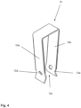
- the apparatus 1 further includes a preferably U-shaped resilient bracket 10 which is shown in Figs. 1 , 2 and 4 and which comprises a first and a second leg 10a, 10b and an opening 10c that is arranged between the first and second leg 10a, 10b.
- the first and second leg 10a, 10b and the opening 10c of the bracket 10 are adapted to be positioned over the peripheral surface of the first and second housing sections 2a, 2b in the second engaging position, in which the first and second legs 10a and 10b urge the two housing sections 2a, 2b towards each other, thereby clamping the inner parts of the first and second housing sections 2a, 2b to the periphery of the busbar 100 which is to be electrically insulated.
- the first engagement means 20 comprise a plurality of first engagement elements 20a which are equidistantly spaced along the longitudinal hinge section 4 at the first housing section 2a and which are separated by first cut-outs 22a.
- the second engagement means 30 comprise a plurality of second engagement elements 30b which are equidistantly spaced along the longitudinal hinge section 4 at the second housing section 2b and which are separated by second cut-outs 32b.
- Each of the first engagement elements 20a comprises a first constricted neck portion 20a1 ( Fig. 5a, 5b ) which projects in a direction away from the opening 6 which receives the connecting portion 106 of the busbar 100 and a first extended head portion 20a2 which is formed thereat.
- Each of the first cut-outs 22a comprises a first extended head section 22a2 which is arranged adjacent to the first constricted neck portion 20a1 and a first constricted neck section 22a1 which is located adjacent the first extended head portion 20a2, as it is shown in Figs. 5a and 5b . As it can be seen from Fig.
- each of the first and second neck sections 22a1 and 22a2 of the first cut-outs 22a extends from a preferably straight rear edge of an adjoining first engagement element 20a to the constricted neck portion 20a1 and extended head portion 20a2 of a first engagement element 20a, thereby forming the shown L-type contour of the first cut-outs 22a.
- each of the second engagement elements 30b comprises a second constricted neck portion 30b1 projecting in a direction away from the opening 6 and a second extended head portion 30b2 formed thereat.
- each of the second cut-outs 32b comprises a second extended head section 32b2 which is positioned adjacent to the second constricted neck portion 30b1, and also comprises a second constricted neck section 32b1 that is located adjacent to the first extended head portion 30b2.
- each of the first and second neck sections 32b1 and 32b2 of the second cut-outs 32b extends from a preferably straight rear edge of an adjoining second engagement element 30b to the constricted neck portion 30b1 and extended head portion 30b2 of a second engagement element 30b, respectively, thereby forming the shown L-type contour of the second cut-outs 32b.
- the width of the first constricted neck portions 20a1 of the first engagement elements 20a is smaller than the width of said second constricted neck sections 32b1 of the second cut-outs 32b point.
- the width of the second constricted neck portions 30b1 of the second engagement elements 30b is smaller than the width of the first constricted neck sections 22a1 of the first cut-outs 22a, as it is indicated in Figs. 5a and 5b by the dash dotted lines.
- each of the first and second extended head portions 20a2, 30b2 comprises a nose-type projection 9a, 9b.
- the orientation of the nose-type projections 9a, 9b is such that the projections 9a which are formed at the first extended head portions 20a2 of the first engagement elements 20a extend in a direction which is parallel and opposite to the nose-type projections 9b which are formed at the second extended head portions 30b2 of the second engagement elements 30b.
- first and second housing sections 2a, 2b can be manufactured as identical parts in one and the same mold and can be assembled to the final housing 2 by simply turning one part upside down relative to the other complementary part before engaging the first and second engagement means 20, 30.
- first and second nose-type projections 9a, 9b abutting each other in the second clamping position of the apparatus 1 provide for an increased flexibility of the hinge section 4.
- opposing grooves 8 may be formed on the peripheral surfaces of the first and second housing section 2a, 2b for receiving the legs 10a, 10b of the resilient bracket 10.
- complementary locking elements in form of hooks may be formed inside the grooves 8, which engage with associated openings 12a formed at the legs 10a, 10b of each bracket 10 after moving a bracket 10 into a desired end position on the periphery of the housing 2.
- one pair of grooves 8 for receiving an associated resilient bracket 10 may also be provided at the top and at the bottom of the housing 2, with the grooves 8 extending in a vertical direction parallel to the imaginary axis ( Fig. 1 ) extending along the hinge section 4 of the mounted apparatus 1.
- These additional grooves and resilient brackets 10 allow for an improved stability of the apparatus 1 when it is mounted at the busbar 100.
- further locking elements like jaws or the like (not shown) may be provided at the inner surface of the first and/or second housing section 2a, 2b. These further locking elements are adapted to interact with a connecting portion 106 of a busbar, in order to provide for additional friction or even a form locking interaction which prevent the housing from slipping off the connecting portion 106 after mounting the housing 2 to the busbar 100.
Description
- The invention is related to an apparatus for electrically insulating a lateral connecting portion of a laminated multi-phase busbar according to
claim 1. - Multi-phase busbars are used in low voltage switchgears to conduct and distribute alternating electrical current to different electrical devices which are installed in switch gear cabinets. In order to conduct all three or even more phases of an alternating current in a single busbar, laminated multi-phase busbars have been developed which comprise a base layer and a cover layer of electrically insulating material between which two or more layers of conducting sheet metal, in particular copper sheets, are arranged which are electrically insulated from each other by means of insulating intermediate layers.
- An afore-described busbar in which the different layers are laminated to each other by means of liquid resin is described in
DE 10 2005 015 945 B4 - In order to supply electric energy from a power source to a laminated multi-phase busbar, it is known to remove the insulating material in a lateral section of the sandwich of layers and expand the uncoated conducting layers which project from the intermediate insulating layers, so as to provide for e.g. four lateral connecting portions, that is one for each phase and one for protective earth, to which the terminals of the electric power source can be connected.
- The lateral connecting portions are also used to provide for an electrical connection between different busbars in two or more switch gear cabinets which are arranged in a row. Moreover, the lateral connecting portions serve to reduce the lengths of laminated busbars, as long busbars for large switchgear cabinets can be spilt up into a plurality of shorter busbar sections which are joint at the customer site, in order to ease handling and reduce transportation costs.
- The electrical connection of the conducting layers of one busbar or busbar section to the conducting layers of an adjoining busbar or bus bar section at the lateral connecting portions is usually done by means of bridging elements each of which has two terminal members which are clamped to the contact sections of the conducting layers which are to be electrically connected. Bridging elements for electrically interconnecting the connecting portions are disclosed in
WO2018114690A1 of the applicant, and inEP 0 025 947 A1 andJP 2019080484A - One problem of the afore-described laminated busbars is that the connecting portions of a busbar which are not used for interconnecting the same to a neighboring busbar or a power supply, must be electrically insulated when using the busbar, in order to avoid any risk of an electrical shock to operators, or sparking when energizing the busbar.
- Accordingly, it is an object of the present invention to provide an apparatus which allows for a cost efficient and reliable electrical insulation of the connecting portion of a laminated multi-phase busbar.
- This object is achieved by an apparatus as claimed in
claim 1. - According to the invention, an apparatus for electrically insulating a lateral connecting portion of a laminated multi-phase busbar comprising comprises an elongated housing which is composed of a first and a second housing section each of which is made of an electrically insulating material like plastics, e.g. GPO-3 or another suitable sheet molding compound with insulating properties. The first and the second housing sections are pivotally connected to each other along a hinge section which extends in a longitudinal direction of the housing. The elongated housing has a length which in a preferred embodiment extends over the entire length of a lateral connecting portion of a laminated busbar.
- Opposite to the longitudinal hinge section an opening is provided between the two housing sections which is adapted to receive the connecting portion of a laminated multi-phase busbar, so that the housing functions as an insulating cover which entirely covers the terminals located in the connecting portion of a busbar when applying an electric voltage to the different conducting layers of the busbar.
- In order to provide for the hinge portion and allow the first and second housing section to be mounted together and to be adapted to the thickness of a busbar, which might vary due to the number and thickness of the conducting layers used, the first housing section comprises a plurality of first engagement means and the second housing section comprises a plurality of second complementary engagement means which are adapted to engage with the first engagement means when pivoting the first and second housing section towards each other from a first assembling position to a second clamping position. In the first assembling position, in which the first and second housing sections are opened up in a rather linear configuration, comparable to an open book, the first engagement means of the first housing section and the second engagement means of the second housing section can be moved above and into each other. After connecting the engagement means of first and second housing sections to each other, so that they form a hinge which extends along the hinge section of the housing, both housing sections are pivoted about an imaginary axis towards each other which axis extends in a direction that is parallel to the lateral edge of the connecting portion of a busbar.
- The apparatus further comprises a resilient, preferably U-shaped or V-shaped bracket which has a first and a second leg and an opening that is arranged between the first and second leg. The first and second legs of the resilient bracket have a length and distance to each other which allows them to be positioned over the peripheral surface of the first and second housing section of the housing after both housing sections have been pivoted around the afore mentioned imaginary axis against the peripheral surface and components which are located in the connecting portion on either side of the lateral connecting portion of the busbar. In this second clamping position, in which the first and second housing sections are firmly mechanically connected to each other in the direction of the pivot axis, thereby forming the hinge section, the connecting portion of the busbar extends through the opening opposite of the hinge section, and the first and second leg of the resilient bracket apply a biasing force to the peripheral surfaces of the first and second housing section which urges the housing sections towards each other, thereby clamping the housing to the connecting portion of the busbar. Though the resilient bracket may be formed of any suitable resilient plastics material like polyamide or the like, the material used is preferably metal, e.g. spring steel or stainless steel, because the electrical insulation is provided by the insulating material of the first and second housing sections against which the legs of the bracket abut.
- The apparatus has the advantage that it can be manufactured at low costs, e.g. by heat molding a sheet molding compound or by injection molding, and is easy to assemble and mountable to a busbar. Due to the resilient bracket and the long travel of the resilient legs, the apparatus reliably clamps to the connecting portions of busbars of varying thicknesses without the need of a time-consuming adjustments of clamping screws or the like. Another advantage of the apparatus according to the invention can be seen in that temperature variations of the ambient air do not significantly affect the magnitude of the clamping force, and as desired number of brackets, e.g. 2 or more brackets, can be mounted side by side at the front side of the apparatus, in order to provide for a sufficient clamping force when mounting the apparatus to large busbars.
- According to another object of the invention, the first engagement means comprise a plurality of first engagement elements which are preferably equidistantly spaced along the longitudinal hinge section at the first housing section. The first engagement elements are separated by first cut-outs, wherein all of the cut-outs do preferably have an identical or at least substantially identical shape. In a similar manner, the second engagement means comprise a plurality of second engagement elements which are equidistantly spaced along the longitudinal hinge section which is provided at the second housing section. In the same way as the first engagement elements, also the second engagement elements have a preferably identical shape and are separated by intermediate second cut-outs as described herein before with regard to the first engagement elements.
- Preferably, each of the first engagement elements comprises a first constricted neck portion which projects in a direction away from the opening which receives the connecting portions of the laminated busbar and a first extended head portion which is formed at the constricted neck portion.
- In this embodiment, each of the first cut-outs comprises a first extended head section which is located adjacent to the first constricted neck portion, and a first constricted neck section which is located adjacent to the first extended head portion.
- Moreover, each of the second engagement elements preferably comprises a second constricted neck portion which projects in a direction away from the opening and a second extended head portion which is formed at the second constricted neck portion. Each of the second cut-outs comprises a second extended head section which is located adjacent to the second constricted neck portion and a second constricted neck section which is located adjacent the first extended head portion.
- In a most preferred embodiment of the invention which provides for a very easy and fast assembling of the apparatus, the width of the first constricted neck portions of the first engagement elements is smaller than the width of the second constricted neck sections of the second cut-outs. Moreover, the width of the second constricted neck portions of the second engagement elements is smaller than the width of the first constricted neck sections of the first cut-outs. This layout of the first and second engagement elements provides for the advantage that the first and second housing sections can be joined together by simply inserting the first constricted neck portions of the first housing section into the corresponding second constricted neck sections of the cut-outs formed at the second housing section and vice versa while holding the first and the second housing sections in the V-shaped configuration. After the insertion of the constricted neck portions into the associated neck sections of the cut-outs (openings), the first and the second housing sections can be pivoted towards each other in order to constitute the hinge which extends along the longitudinal hinge section.
- According to a further object of the invention, each of the first and second extended head portions of the afore-described embodiment may comprise a nose-type projection. The nose-type projections which are formed at the first extended head portions of the first engagement elements extend in a direction which is preferably parallel and opposite to the direction of nose-type projections of the second extended head portions which are formed at the second engagement elements.
- This construction provides for the advantage that the first and second housing section may be formed as identical parts which are assembled upside down, in order to provide for the housing of the apparatus which serves as a protective cover for the end portions of the busbar. As a result, the production costs for an additional mold may be saved.
- According to a further aspect of the present invention, opposing grooves may be provided on the peripheral surfaces of the first and second housing section. These opposing grooves are adapted to receive the legs of the resilient bracket, thereby safely holding the brackets in place when mounting them on the outer periphery of the first and second housing sections.
- In this embodiment of the invention complementary locking elements, in particular hooks and openings for receiving the hooks or hooks and ridges, may be advantageously provided at the first and second leg of each resilient bracket and in the associated grooves for receiving the legs of the brackets, in order to prevent the brackets from slipping off the peripheral surface of the housing in a direction perpendicular to the direction of the pivotal axis extending along the hinge portion.
- According to another aspect of the invention further locking elements may be provided at the inner surface of the first and/or second housing section. These further locking elements are preferably adapted to mechanically interact with an associated connecting portion of a laminated multi-phase busbar, in order to prevent the housing from slipping off a lateral connecting portion after mounting the housing to the lateral connecting portion of the laminated multi-phase busbar.
- The invention is hereinafter described with reference to the accompanying drawings.
- In the drawings
- Fig. 1
- is schematic view of a laminated multi-phase busbar with an apparatus according to the invention mounted thereat,
- Fig. 2
- is a cross sectional view of the apparatus of
Fig. 1 along a plane extending through one of the brackets, - Fig. 3a
- is a 3-dimensional view of the outer side of the first housing section of the apparatus of
Fig. 1 , - Fig. 3b
- is a 3-dimensional view of the outer side of the second housing section of the apparatus of
Fig. 1 , - Fig. 4
- is a 3-dimensional view of a preferred embodiment of a resilient bracket,
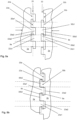
- Fig. 5a
- is a partial top view of the first and second engagement elements before engaging the same with each other, and
- Fig. 5b
- is a partial top view of the first and second engagement elements after engaging the same.
- As it is shown in
Figs. 1 and2 , a laminatedmulti-phase busbar 100 comprises a plurality of conductinglayers 102 and insulatinglayers 104 which are arranged between the conducting layers 102. The conducting layers 102 of the laminatedmulti-phase busbar 100 which may be accommodated in a first switch gear cabinet (not shown) project from the insulatinglayers 104 and form alateral connecting portion 106 with contact surfaces 102.1 to 102.3, to which an electric power supply (not shown) or afurther busbar 100 may be connected. - In order to electrically insulate the
lateral connecting portion 106 of thebusbar 100, anapparatus 1 which is shown inFigs. 1 to 5 comprises anelongated housing 2 which includes a first and asecond housing section housing sections hinge section 4, which is indicated inFig. 1 by the dashed dotted line and which extends in a longitudinal direction of thehousing 2. Anopening 6 is arranged opposite to thelongitudinal hinge section 4 which receives the connectingportion 106 of thebusbar 100, as it is indicated inFig. 1 . - As it can be best seen from
Figs. 1 ,3a ,3b and5a , thefirst housing section 2a comprises a plurality of first engagement means 20, and thesecond housing section 2b comprises a plurality of second engagement means 30 which are complementary to the first engagement means 20 and which are adapted to engage with the first engagement means 20 when pivoting thehousing sections Fig. 5b ) to a second clamping position (Fig. 1 andFig. 2 ). - The
apparatus 1 further includes a preferably U-shapedresilient bracket 10 which is shown inFigs. 1 ,2 and4 and which comprises a first and asecond leg opening 10c that is arranged between the first andsecond leg second leg opening 10c of thebracket 10 are adapted to be positioned over the peripheral surface of the first andsecond housing sections second legs housing sections second housing sections busbar 100 which is to be electrically insulated. - As it is further shown in
Figs. 3a ,3b and5a, 5b , the first engagement means 20 comprise a plurality offirst engagement elements 20a which are equidistantly spaced along thelongitudinal hinge section 4 at thefirst housing section 2a and which are separated by first cut-outs 22a. The second engagement means 30 comprise a plurality ofsecond engagement elements 30b which are equidistantly spaced along thelongitudinal hinge section 4 at thesecond housing section 2b and which are separated by second cut-outs 32b. - Each of the
first engagement elements 20a comprises a first constricted neck portion 20a1 (Fig. 5a, 5b ) which projects in a direction away from theopening 6 which receives the connectingportion 106 of thebusbar 100 and a first extended head portion 20a2 which is formed thereat. Each of the first cut-outs 22a comprises a first extended head section 22a2 which is arranged adjacent to the first constricted neck portion 20a1 and a first constricted neck section 22a1 which is located adjacent the first extended head portion 20a2, as it is shown inFigs. 5a and 5b . As it can be seen fromFig. 5a , each of the first and second neck sections 22a1 and 22a2 of the first cut-outs 22a extends from a preferably straight rear edge of an adjoiningfirst engagement element 20a to the constricted neck portion 20a1 and extended head portion 20a2 of afirst engagement element 20a, thereby forming the shown L-type contour of the first cut-outs 22a. - Moreover, as it is further shown in
Figs. 5a and 5b , each of thesecond engagement elements 30b comprises a second constricted neck portion 30b1 projecting in a direction away from theopening 6 and a second extended head portion 30b2 formed thereat. In a similar way, each of the second cut-outs 32b comprises a second extended head section 32b2 which is positioned adjacent to the second constricted neck portion 30b1, and also comprises a second constricted neck section 32b1 that is located adjacent to the first extended head portion 30b2. As it can be seen fromFig. 5a , each of the first and second neck sections 32b1 and 32b2 of the second cut-outs 32b extends from a preferably straight rear edge of an adjoiningsecond engagement element 30b to the constricted neck portion 30b1 and extended head portion 30b2 of asecond engagement element 30b, respectively, thereby forming the shown L-type contour of the second cut-outs 32b. - In order to easily engage the
engagement elements 20a arranged at thefirst housing section 2a with the secondcomplementary engagement elements 30b of thesecond housing section 2b, the width of the first constricted neck portions 20a1 of thefirst engagement elements 20a is smaller than the width of said second constricted neck sections 32b1 of the second cut-outs 32b point. In addition here to, the width of the second constricted neck portions 30b1 of thesecond engagement elements 30b is smaller than the width of the first constricted neck sections 22a1 of the first cut-outs 22a, as it is indicated inFigs. 5a and 5b by the dash dotted lines. - As it can be seen from
Fig. 5a and 5b , each of the first and second extended head portions 20a2, 30b2 comprises a nose-type projection type projections projections 9a which are formed at the first extended head portions 20a2 of thefirst engagement elements 20a extend in a direction which is parallel and opposite to the nose-type projections 9b which are formed at the second extended head portions 30b2 of thesecond engagement elements 30b. - This however provides for the advantage, that the first and
second housing sections final housing 2 by simply turning one part upside down relative to the other complementary part before engaging the first and second engagement means 20, 30. Moreover, the first and second nose-type projections Fig. 1 ) provide for an increased flexibility of thehinge section 4. - As it is further shown in
Fig. 1 and3a , opposinggrooves 8 may be formed on the peripheral surfaces of the first andsecond housing section legs resilient bracket 10. - In order to prevent the
legs grooves 8, complementary locking elements in form of hooks, preferablybarbs 12b, may be formed inside thegrooves 8, which engage with associatedopenings 12a formed at thelegs bracket 10 after moving abracket 10 into a desired end position on the periphery of thehousing 2. However, it is also conceivable to provide the hooks at thelegs brackets 10 and openings, or alternatively ridges (not shown), inside thegrooves 8. As it is further shown inFig. 1 , one pair ofgrooves 8 for receiving an associatedresilient bracket 10 may also be provided at the top and at the bottom of thehousing 2, with thegrooves 8 extending in a vertical direction parallel to the imaginary axis (Fig. 1 ) extending along thehinge section 4 of themounted apparatus 1. These additional grooves andresilient brackets 10 allow for an improved stability of theapparatus 1 when it is mounted at thebusbar 100. - Eventually, further locking elements like jaws or the like (not shown) may be provided at the inner surface of the first and/or
second housing section portion 106 of a busbar, in order to provide for additional friction or even a form locking interaction which prevent the housing from slipping off the connectingportion 106 after mounting thehousing 2 to thebusbar 100. -
- 1
- apparatus
- 2
- housing
- 2a
- first housing section
- 2b
- second housing section
- 4
- hinge section
- 6
- opening for receiving connecting portion of busbar
- 8
- grooves in periphery of housing sections
- 9a, 9b
- nose-type projection
- 10
- resilient bracket
- 10a
- first leg of resilient bracket
- 10b
- second leg of resilient bracket
- 10c
- opening of resilient bracket
- 12a, b
- complementary locking elements
- 20
- first engagement means
- 20a
- first engagement elements
- 20a1
- constricted neck portion of first engagement elements
- 20a2
- extended head portion of first engagement elements
- 22a
- first cut-outs between first engagement elements
- 22a1
- constricted neck section of first cut-outs
- 22a2
- extended head section of first cut-outs
- 30
- second engagement means
- 30b
- second engagement elements
- 30b1
- constricted neck portion of second engagement elements
- 30b2
- extended head portion of second engagement elements
- 32b
- second cut-outs between second engagement elements
- 32b1
- constricted neck section of second cut-outs
- 32b2
- extended head section of second cut-outs
- 100
- laminated multi-phase busbar
- 102
- conducting layers
- 102.1
- contact surface
- 102.2
- contact surface
- 102.3
- contact surface
- 104
- insulating layers
- 106
- lateral connecting portion
Claims (10)
- Apparatus (1) for electrically insulating a lateral connecting portion (106) of a laminated multi-phase busbar (100), the apparatus being characterized by comprising:an elongated housing (2) having a first and a second housing section (2a, 2b) made of an electrically insulating material which are pivotally connected to each other along a hinge section (4) extending in a longitudinal direction of said housing (2) and an opening (6) arranged opposite to said longitudinal hinge section (4) for receiving a connecting portion (106) of a laminated multi-phase busbar (100),wherein said first housing section (2a) comprises a plurality of first engagement (20) means and said second housing section (2b) comprises a plurality of second complementary engagement means (30) which are adapted to engage with said first engagement means (20) when pivoting said first and second housing section (2a, 2b) towards each other from a first assembling position to a second clamping position; said apparatus (1) further comprising a resilient bracket (10) having a first and a second leg (10a, 10b) and an opening (10c) arranged between said first and second leg (10a, 10b), said first and second leg (10a, 10b) and said opening (10c) of said bracket (10) being adapted to be positioned over the peripheral surface of said first and second housing section (2a, 2b) in said second engaging position for urging said first and second housing (2a, 2b) section towards each other.
- Apparatus according to claim 1,
characterized in that said first engagement means (20) comprise a plurality of first engagement elements (20a) which are equidistantly spaced along said longitudinal hinge section (4) at said first housing section (2a) and which are separated by first cut-outs (22a), and that said second engagement means (30) comprise a plurality of second engagement elements (30b) which are equidistantly spaced along said longitudinal hinge section (4) at said second housing section (2b) and which are separated by second cut-outs (32b). - Apparatus according to claim 2,
characterized in that each of said first engagement elements (20a) comprises a first constricted neck portion (20a1) projecting in a direction away from said opening (6) and a first extended head portion (20a2) formed thereat, and in that each of said first cut-outs (22a) comprises a first extended head section (22a2) adjacent to said first constricted neck portion (20a1) and a first constricted neck section (22a1) adjacent said first extended head portion (20a2). - Apparatus according to claim 2 or 3,
characterized in that each of said second engagement elements (30b) comprises a second constricted neck portion (30b1) projecting in a direction away from said opening 6 and a second extended head portion (30b2) formed thereat, and in that each of said second cut-outs (32b) comprises a second extended head section (32b2) adjacent to said second constricted neck portion (30b1) and a second constricted neck section (32b1) adjacent said first extended head portion (30b2). - Apparatus according to claims 3 and 4,
characterized in that the width of said first constricted neck portions (20a1) of said first engagement elements (20a) is smaller than the width of said second constricted neck sections (32b1) of said second cut-outs (32b) and that the width of said second constricted neck portions (30b1) of said second engagement elements (30b) is smaller than the width of said first constricted neck sections (22a1) of said first cut-outs (22a). - Apparatus according to any of the claims 3 to 5,
characterized in that each of said first and second extended head portions (20a2, 30b2) comprises a nose-type projection, wherein said nose-type projections formed at said first extended head portions (20a2) of said first engagement elements (20a) extend in a direction parallel and opposite to said nose-type projections of said second extended head portions (30b2) which are formed at said second engagement elements (30b). - Apparatus according to any of the preceding claims,
characterized in that said first and second housing section (2a, 2b) are identical. - Apparatus according to any of the preceding claims,
characterized in that opposing grooves (8) are formed on the peripheral surfaces of the first and second housing section (2a, 2b) for receiving the legs (10a, 10b) of the resilient bracket (10). - Apparatus according to claim 8,
characterized in that complementary locking elements (12a, 12b), in particular hooks and openings for receiving the hooks or hooks and ridges, are provided at said legs (10a, 10b) of said resilient bracket (10) and at said associated grooves (8), for preventing the bracket (10) from slipping off the peripheral surface of said housing (2). - Apparatus according to any of the preceding claims,
characterized in that further locking elements are provided at the inner surface of said first and/or second housing section, said further locking elements being adapted to interact with a connecting portion (106) of a laminated multi-phase busbar (100), to prevent said housing from slipping off a lateral connecting portion (106) after mounting the housing (2) to said lateral connecting portion (106).
Applications Claiming Priority (1)
| Application Number | Priority Date | Filing Date | Title |
|---|---|---|---|
| PCT/EP2020/051912 WO2021151464A1 (en) | 2020-01-27 | 2020-01-27 | Apparatus for electrically insulating a lateral connecting portion of a laminated multi-phase busbar |
Publications (2)
| Publication Number | Publication Date |
|---|---|
| EP4097812A1 EP4097812A1 (en) | 2022-12-07 |
| EP4097812B1 true EP4097812B1 (en) | 2023-12-20 |
Family
ID=69326531
Family Applications (1)
| Application Number | Title | Priority Date | Filing Date |
|---|---|---|---|
| EP20702278.1A Active EP4097812B1 (en) | 2020-01-27 | 2020-01-27 | Apparatus for electrically insulating a lateral connecting portion of a laminated multi-phase busbar |
Country Status (4)
| Country | Link |
|---|---|
| US (1) | US20220360065A1 (en) |
| EP (1) | EP4097812B1 (en) |
| CN (1) | CN114631239B (en) |
| WO (1) | WO2021151464A1 (en) |
Family Cites Families (22)
| Publication number | Priority date | Publication date | Assignee | Title |
|---|---|---|---|---|
| US3202756A (en) * | 1963-04-02 | 1965-08-24 | Square D Co | Insulated bus bars and assembly |
| US3384856A (en) * | 1966-04-15 | 1968-05-21 | Gen Electric | Multi-phase electric power distribution system |
| US3726988A (en) * | 1972-07-17 | 1973-04-10 | Ite Imperial Corp | Weatherproof bus duct |
| US3882265A (en) * | 1974-05-03 | 1975-05-06 | Gen Electric | Electrical busway with improved joint construction |
| FR2466122A1 (en) * | 1979-09-19 | 1981-03-27 | Cit Alcatel | ENERGY DISTRIBUTION BAR |
| JPH0617326U (en) * | 1992-08-05 | 1994-03-04 | 矢崎総業株式会社 | Bus bar wiring board |
| US5442135A (en) * | 1993-03-25 | 1995-08-15 | Siemens Energy & Automation, Inc. | Electrical power distribution busway and housing |
| DE19540339A1 (en) * | 1995-10-28 | 1997-04-30 | Kloeckner Moeller Gmbh | Outlet and device box of an energy distribution system |
| JP3729122B2 (en) * | 2001-11-09 | 2005-12-21 | 日産自動車株式会社 | Power wiring structure |
| EP1455617A1 (en) * | 2001-12-08 | 2004-09-15 | Rittal GmbH & Co. KG | Frame section |
| DE102004018904B4 (en) * | 2004-04-15 | 2013-11-14 | Wago Verwaltungsgesellschaft Mbh | Screwless busbar connection for electrical terminals |
| DE102005015945B4 (en) | 2005-04-07 | 2015-07-02 | Abb Ag | Contact device for a two- or multi-phase busbar arrangement |
| DE102006058327B3 (en) * | 2006-12-11 | 2008-05-15 | Siemens Ag | Conductor rail packet, has inner conductor rail of packet provided with reticular rail and recesses, which are arranged corresponding to cross webs of corresponding reticular rail |
| GB2502926B (en) * | 2011-03-31 | 2014-11-26 | Eldre Corp | Multiple wrapped laminated bus bar system and method |
| CN202183579U (en) * | 2011-06-23 | 2012-04-04 | 扬州市天海滑线电气有限公司 | Multilayer dense insulation type bus duct |
| WO2013160920A1 (en) * | 2012-04-24 | 2013-10-31 | IAM S.r.l. | Adaptable prefabricated laminated busbarsystem and a method for a adapting the length of said busbarsystem |
| CN203039312U (en) * | 2013-01-22 | 2013-07-03 | 广东伊顿母线有限公司 | Bus duct splicing apparatus |
| US9190791B1 (en) * | 2014-07-31 | 2015-11-17 | Power Distribution, Inc. | Electrical busway splice connector |
| CN205753291U (en) * | 2016-05-12 | 2016-11-30 | 镇江加勒智慧电力科技股份有限公司(中外合资) | Master row insulating protective plate |
| EP3555977B1 (en) * | 2016-12-19 | 2021-07-14 | ABB Schweiz AG | Multi-phase busbar for conducting electric energy and method of manufacturing the same |
| JP7042466B2 (en) * | 2017-10-26 | 2022-03-28 | 共同カイテック株式会社 | Partial structure in the bus duct trunk line, other bus duct structures, bus duct system and connection method of bus duct system. |
| CN111954962B (en) * | 2018-04-16 | 2024-01-23 | Abb瑞士股份有限公司 | Device for electrically interconnecting two laminated polyphase bus bars and switchgear cabinet comprising such a device |
-
2020
- 2020-01-27 CN CN202080076287.XA patent/CN114631239B/en active Active
- 2020-01-27 WO PCT/EP2020/051912 patent/WO2021151464A1/en unknown
- 2020-01-27 EP EP20702278.1A patent/EP4097812B1/en active Active
-
2022
- 2022-07-22 US US17/870,974 patent/US20220360065A1/en active Pending
Also Published As
| Publication number | Publication date |
|---|---|
| CN114631239A (en) | 2022-06-14 |
| CN114631239B (en) | 2023-12-26 |
| EP4097812A1 (en) | 2022-12-07 |
| US20220360065A1 (en) | 2022-11-10 |
| WO2021151464A1 (en) | 2021-08-05 |
Similar Documents
| Publication | Publication Date | Title |
|---|---|---|
| US20200194977A1 (en) | Conductor for a power distribution system | |
| US5055059A (en) | Current connection member for large amperages, especially to be used in metal-enclosed electric systems | |
| EP4097812B1 (en) | Apparatus for electrically insulating a lateral connecting portion of a laminated multi-phase busbar | |
| CA2264791A1 (en) | Busway elbow device | |
| US6142807A (en) | High current and low current electrical busway systems having compatible bus plug | |
| WO2019201429A1 (en) | Apparatus for electrically interconnecting two laminated multi-phase busbars and switchboard arrangement including such an apparatus | |
| EP3382832A1 (en) | Power bus connection system with fusible conductive material | |
| EP3981049B1 (en) | Coupling element for electrically coupling the lateral connecting portions of a first and second laminated busbar via a circuit breaker and an arrangement including such an element | |
| US11189998B2 (en) | Apparatus for electrically interconnecting two laminated multi-phase busbars | |
| EP3817025B1 (en) | Conductor assembly for a power distribution system | |
| CA2134053C (en) | Meter socket pan and assembly | |
| EP3817163B1 (en) | Conductor assembly for a power distribution system | |
| EP4145479B1 (en) | An accessory device for a medium voltage vacuum contactor | |
| US10411441B2 (en) | Load centers with neutral bus bars for breaker plug-on neutral connections | |
| CN108432054B (en) | Clamp terminal block for interconnecting two bushings and associated connection piece | |
| KR100931842B1 (en) | switchboard | |
| WO2000027006A1 (en) | Device for connecting bus bars | |
| NZ207374A (en) | Insulative bus bar support |
Legal Events
| Date | Code | Title | Description |
|---|---|---|---|
| STAA | Information on the status of an ep patent application or granted ep patent |
Free format text: STATUS: UNKNOWN |
|
| STAA | Information on the status of an ep patent application or granted ep patent |
Free format text: STATUS: THE INTERNATIONAL PUBLICATION HAS BEEN MADE |
|
| PUAI | Public reference made under article 153(3) epc to a published international application that has entered the european phase |
Free format text: ORIGINAL CODE: 0009012 |
|
| STAA | Information on the status of an ep patent application or granted ep patent |
Free format text: STATUS: REQUEST FOR EXAMINATION WAS MADE |
|
| 17P | Request for examination filed |
Effective date: 20220701 |
|
| AK | Designated contracting states |
Kind code of ref document: A1 Designated state(s): AL AT BE BG CH CY CZ DE DK EE ES FI FR GB GR HR HU IE IS IT LI LT LU LV MC MK MT NL NO PL PT RO RS SE SI SK SM TR |
|
| DAV | Request for validation of the european patent (deleted) | ||
| DAX | Request for extension of the european patent (deleted) | ||
| GRAP | Despatch of communication of intention to grant a patent |
Free format text: ORIGINAL CODE: EPIDOSNIGR1 |
|
| STAA | Information on the status of an ep patent application or granted ep patent |
Free format text: STATUS: GRANT OF PATENT IS INTENDED |
|
| RIC1 | Information provided on ipc code assigned before grant |
Ipc: H02B 1/20 20060101ALN20230816BHEP Ipc: H02G 5/00 20060101AFI20230816BHEP |
|
| INTG | Intention to grant announced |
Effective date: 20230831 |
|
| GRAS | Grant fee paid |
Free format text: ORIGINAL CODE: EPIDOSNIGR3 |
|
| GRAA | (expected) grant |
Free format text: ORIGINAL CODE: 0009210 |
|
| STAA | Information on the status of an ep patent application or granted ep patent |
Free format text: STATUS: THE PATENT HAS BEEN GRANTED |
|
| AK | Designated contracting states |
Kind code of ref document: B1 Designated state(s): AL AT BE BG CH CY CZ DE DK EE ES FI FR GB GR HR HU IE IS IT LI LT LU LV MC MK MT NL NO PL PT RO RS SE SI SK SM TR |
|
| REG | Reference to a national code |
Ref country code: GB Ref legal event code: FG4D |
|
| REG | Reference to a national code |
Ref country code: DE Ref legal event code: R096 Ref document number: 602020023025 Country of ref document: DE |
|
| REG | Reference to a national code |
Ref country code: CH Ref legal event code: EP |
|
| REG | Reference to a national code |
Ref country code: IE Ref legal event code: FG4D |
|
| PG25 | Lapsed in a contracting state [announced via postgrant information from national office to epo] |
Ref country code: GR Free format text: LAPSE BECAUSE OF FAILURE TO SUBMIT A TRANSLATION OF THE DESCRIPTION OR TO PAY THE FEE WITHIN THE PRESCRIBED TIME-LIMIT Effective date: 20240321 |
|
| REG | Reference to a national code |
Ref country code: LT Ref legal event code: MG9D |
|
| PG25 | Lapsed in a contracting state [announced via postgrant information from national office to epo] |
Ref country code: LT Free format text: LAPSE BECAUSE OF FAILURE TO SUBMIT A TRANSLATION OF THE DESCRIPTION OR TO PAY THE FEE WITHIN THE PRESCRIBED TIME-LIMIT Effective date: 20231220 |