EP4097812B1 - Dispostif pour isoler une extrémité de connexion d'un jeu de barres laminées multi phases - Google Patents
Dispostif pour isoler une extrémité de connexion d'un jeu de barres laminées multi phases Download PDFInfo
- Publication number
- EP4097812B1 EP4097812B1 EP20702278.1A EP20702278A EP4097812B1 EP 4097812 B1 EP4097812 B1 EP 4097812B1 EP 20702278 A EP20702278 A EP 20702278A EP 4097812 B1 EP4097812 B1 EP 4097812B1
- Authority
- EP
- European Patent Office
- Prior art keywords
- housing
- section
- constricted neck
- extended head
- outs
- Prior art date
- Legal status (The legal status is an assumption and is not a legal conclusion. Google has not performed a legal analysis and makes no representation as to the accuracy of the status listed.)
- Active
Links
- 230000002093 peripheral effect Effects 0.000 claims description 10
- 230000000295 complement effect Effects 0.000 claims description 9
- 239000012777 electrically insulating material Substances 0.000 claims description 4
- 239000004033 plastic Substances 0.000 description 3
- 229920003023 plastic Polymers 0.000 description 3
- 239000003677 Sheet moulding compound Substances 0.000 description 2
- 238000010292 electrical insulation Methods 0.000 description 2
- 239000011810 insulating material Substances 0.000 description 2
- 239000000463 material Substances 0.000 description 2
- 239000002184 metal Substances 0.000 description 2
- 229910052751 metal Inorganic materials 0.000 description 2
- 230000001681 protective effect Effects 0.000 description 2
- RYGMFSIKBFXOCR-UHFFFAOYSA-N Copper Chemical compound [Cu] RYGMFSIKBFXOCR-UHFFFAOYSA-N 0.000 description 1
- 239000004952 Polyamide Substances 0.000 description 1
- 229910000639 Spring steel Inorganic materials 0.000 description 1
- 239000012080 ambient air Substances 0.000 description 1
- 238000010276 construction Methods 0.000 description 1
- 229910052802 copper Inorganic materials 0.000 description 1
- 239000010949 copper Substances 0.000 description 1
- 238000001746 injection moulding Methods 0.000 description 1
- 238000003780 insertion Methods 0.000 description 1
- 230000037431 insertion Effects 0.000 description 1
- 230000003993 interaction Effects 0.000 description 1
- 239000007788 liquid Substances 0.000 description 1
- 238000004519 manufacturing process Methods 0.000 description 1
- 238000000465 moulding Methods 0.000 description 1
- 229920002647 polyamide Polymers 0.000 description 1
- 239000011347 resin Substances 0.000 description 1
- 229920005989 resin Polymers 0.000 description 1
- 230000035939 shock Effects 0.000 description 1
- 229910001220 stainless steel Inorganic materials 0.000 description 1
- 239000010935 stainless steel Substances 0.000 description 1
Images


Classifications
-
- H—ELECTRICITY
- H02—GENERATION; CONVERSION OR DISTRIBUTION OF ELECTRIC POWER
- H02G—INSTALLATION OF ELECTRIC CABLES OR LINES, OR OF COMBINED OPTICAL AND ELECTRIC CABLES OR LINES
- H02G5/00—Installations of bus-bars
- H02G5/005—Laminated bus-bars
-
- H—ELECTRICITY
- H01—ELECTRIC ELEMENTS
- H01B—CABLES; CONDUCTORS; INSULATORS; SELECTION OF MATERIALS FOR THEIR CONDUCTIVE, INSULATING OR DIELECTRIC PROPERTIES
- H01B13/00—Apparatus or processes specially adapted for manufacturing conductors or cables
- H01B13/06—Insulating conductors or cables
-
- H—ELECTRICITY
- H02—GENERATION; CONVERSION OR DISTRIBUTION OF ELECTRIC POWER
- H02B—BOARDS, SUBSTATIONS OR SWITCHING ARRANGEMENTS FOR THE SUPPLY OR DISTRIBUTION OF ELECTRIC POWER
- H02B1/00—Frameworks, boards, panels, desks, casings; Details of substations or switching arrangements
- H02B1/20—Bus-bar or other wiring layouts, e.g. in cubicles, in switchyards
Definitions
- the invention is related to an apparatus for electrically insulating a lateral connecting portion of a laminated multi-phase busbar according to claim 1.
- Multi-phase busbars are used in low voltage switchgears to conduct and distribute alternating electrical current to different electrical devices which are installed in switch gear cabinets.
- laminated multi-phase busbars have been developed which comprise a base layer and a cover layer of electrically insulating material between which two or more layers of conducting sheet metal, in particular copper sheets, are arranged which are electrically insulated from each other by means of insulating intermediate layers.
- the lateral connecting portions are also used to provide for an electrical connection between different busbars in two or more switch gear cabinets which are arranged in a row. Moreover, the lateral connecting portions serve to reduce the lengths of laminated busbars, as long busbars for large switchgear cabinets can be spilt up into a plurality of shorter busbar sections which are joint at the customer site, in order to ease handling and reduce transportation costs.
- the electrical connection of the conducting layers of one busbar or busbar section to the conducting layers of an adjoining busbar or bus bar section at the lateral connecting portions is usually done by means of bridging elements each of which has two terminal members which are clamped to the contact sections of the conducting layers which are to be electrically connected.
- Bridging elements for electrically interconnecting the connecting portions are disclosed in WO2018114690A1 of the applicant, and in EP 0 025 947 A1 and JP 2019080484A .
- One problem of the afore-described laminated busbars is that the connecting portions of a busbar which are not used for interconnecting the same to a neighboring busbar or a power supply, must be electrically insulated when using the busbar, in order to avoid any risk of an electrical shock to operators, or sparking when energizing the busbar.
- an apparatus for electrically insulating a lateral connecting portion of a laminated multi-phase busbar comprising comprises an elongated housing which is composed of a first and a second housing section each of which is made of an electrically insulating material like plastics, e.g. GPO-3 or another suitable sheet molding compound with insulating properties.
- the first and the second housing sections are pivotally connected to each other along a hinge section which extends in a longitudinal direction of the housing.
- the elongated housing has a length which in a preferred embodiment extends over the entire length of a lateral connecting portion of a laminated busbar.
- an opening is provided between the two housing sections which is adapted to receive the connecting portion of a laminated multi-phase busbar, so that the housing functions as an insulating cover which entirely covers the terminals located in the connecting portion of a busbar when applying an electric voltage to the different conducting layers of the busbar.
- the first housing section comprises a plurality of first engagement means and the second housing section comprises a plurality of second complementary engagement means which are adapted to engage with the first engagement means when pivoting the first and second housing section towards each other from a first assembling position to a second clamping position.
- first assembling position in which the first and second housing sections are opened up in a rather linear configuration, comparable to an open book, the first engagement means of the first housing section and the second engagement means of the second housing section can be moved above and into each other.
- both housing sections After connecting the engagement means of first and second housing sections to each other, so that they form a hinge which extends along the hinge section of the housing, both housing sections are pivoted about an imaginary axis towards each other which axis extends in a direction that is parallel to the lateral edge of the connecting portion of a busbar.
- the apparatus further comprises a resilient, preferably U-shaped or V-shaped bracket which has a first and a second leg and an opening that is arranged between the first and second leg.
- the first and second legs of the resilient bracket have a length and distance to each other which allows them to be positioned over the peripheral surface of the first and second housing section of the housing after both housing sections have been pivoted around the afore mentioned imaginary axis against the peripheral surface and components which are located in the connecting portion on either side of the lateral connecting portion of the busbar.
- the connecting portion of the busbar extends through the opening opposite of the hinge section, and the first and second leg of the resilient bracket apply a biasing force to the peripheral surfaces of the first and second housing section which urges the housing sections towards each other, thereby clamping the housing to the connecting portion of the busbar.
- the resilient bracket may be formed of any suitable resilient plastics material like polyamide or the like, the material used is preferably metal, e.g. spring steel or stainless steel, because the electrical insulation is provided by the insulating material of the first and second housing sections against which the legs of the bracket abut.
- the apparatus has the advantage that it can be manufactured at low costs, e.g. by heat molding a sheet molding compound or by injection molding, and is easy to assemble and mountable to a busbar. Due to the resilient bracket and the long travel of the resilient legs, the apparatus reliably clamps to the connecting portions of busbars of varying thicknesses without the need of a time-consuming adjustments of clamping screws or the like. Another advantage of the apparatus according to the invention can be seen in that temperature variations of the ambient air do not significantly affect the magnitude of the clamping force, and as desired number of brackets, e.g. 2 or more brackets, can be mounted side by side at the front side of the apparatus, in order to provide for a sufficient clamping force when mounting the apparatus to large busbars.
- the first engagement means comprise a plurality of first engagement elements which are preferably equidistantly spaced along the longitudinal hinge section at the first housing section.
- the first engagement elements are separated by first cut-outs, wherein all of the cut-outs do preferably have an identical or at least substantially identical shape.
- the second engagement means comprise a plurality of second engagement elements which are equidistantly spaced along the longitudinal hinge section which is provided at the second housing section.
- the second engagement elements have a preferably identical shape and are separated by intermediate second cut-outs as described herein before with regard to the first engagement elements.
- each of the first engagement elements comprises a first constricted neck portion which projects in a direction away from the opening which receives the connecting portions of the laminated busbar and a first extended head portion which is formed at the constricted neck portion.
- each of the first cut-outs comprises a first extended head section which is located adjacent to the first constricted neck portion, and a first constricted neck section which is located adjacent to the first extended head portion.
- each of the second engagement elements preferably comprises a second constricted neck portion which projects in a direction away from the opening and a second extended head portion which is formed at the second constricted neck portion.
- Each of the second cut-outs comprises a second extended head section which is located adjacent to the second constricted neck portion and a second constricted neck section which is located adjacent the first extended head portion.
- the width of the first constricted neck portions of the first engagement elements is smaller than the width of the second constricted neck sections of the second cut-outs.
- the width of the second constricted neck portions of the second engagement elements is smaller than the width of the first constricted neck sections of the first cut-outs.
- each of the first and second extended head portions of the afore-described embodiment may comprise a nose-type projection.
- the nose-type projections which are formed at the first extended head portions of the first engagement elements extend in a direction which is preferably parallel and opposite to the direction of nose-type projections of the second extended head portions which are formed at the second engagement elements.
- first and second housing section may be formed as identical parts which are assembled upside down, in order to provide for the housing of the apparatus which serves as a protective cover for the end portions of the busbar.
- the production costs for an additional mold may be saved.
- opposing grooves may be provided on the peripheral surfaces of the first and second housing section. These opposing grooves are adapted to receive the legs of the resilient bracket, thereby safely holding the brackets in place when mounting them on the outer periphery of the first and second housing sections.
- complementary locking elements in particular hooks and openings for receiving the hooks or hooks and ridges, may be advantageously provided at the first and second leg of each resilient bracket and in the associated grooves for receiving the legs of the brackets, in order to prevent the brackets from slipping off the peripheral surface of the housing in a direction perpendicular to the direction of the pivotal axis extending along the hinge portion.
- further locking elements may be provided at the inner surface of the first and/or second housing section. These further locking elements are preferably adapted to mechanically interact with an associated connecting portion of a laminated multi-phase busbar, in order to prevent the housing from slipping off a lateral connecting portion after mounting the housing to the lateral connecting portion of the laminated multi-phase busbar.
- a laminated multi-phase busbar 100 comprises a plurality of conducting layers 102 and insulating layers 104 which are arranged between the conducting layers 102.
- the conducting layers 102 of the laminated multi-phase busbar 100 which may be accommodated in a first switch gear cabinet (not shown) project from the insulating layers 104 and form a lateral connecting portion 106 with contact surfaces 102.1 to 102.3, to which an electric power supply (not shown) or a further busbar 100 may be connected.
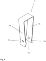
- an apparatus 1 which is shown in Figs. 1 to 5 comprises an elongated housing 2 which includes a first and a second housing section 2a, 2b made of an electrically insulating material, in particular plastics.
- the two housing sections 2a and 2b are pivotally connected to each other along a hinge section 4, which is indicated in Fig. 1 by the dashed dotted line and which extends in a longitudinal direction of the housing 2.
- An opening 6 is arranged opposite to the longitudinal hinge section 4 which receives the connecting portion 106 of the busbar 100, as it is indicated in Fig. 1 .
- the first housing section 2a comprises a plurality of first engagement means 20
- the second housing section 2b comprises a plurality of second engagement means 30 which are complementary to the first engagement means 20 and which are adapted to engage with the first engagement means 20 when pivoting the housing sections 2a, 2b towards each other from a first assembling position ( Fig. 5b ) to a second clamping position ( Fig. 1 and Fig. 2 ).
- the apparatus 1 further includes a preferably U-shaped resilient bracket 10 which is shown in Figs. 1 , 2 and 4 and which comprises a first and a second leg 10a, 10b and an opening 10c that is arranged between the first and second leg 10a, 10b.
- the first and second leg 10a, 10b and the opening 10c of the bracket 10 are adapted to be positioned over the peripheral surface of the first and second housing sections 2a, 2b in the second engaging position, in which the first and second legs 10a and 10b urge the two housing sections 2a, 2b towards each other, thereby clamping the inner parts of the first and second housing sections 2a, 2b to the periphery of the busbar 100 which is to be electrically insulated.
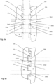
- the first engagement means 20 comprise a plurality of first engagement elements 20a which are equidistantly spaced along the longitudinal hinge section 4 at the first housing section 2a and which are separated by first cut-outs 22a.
- the second engagement means 30 comprise a plurality of second engagement elements 30b which are equidistantly spaced along the longitudinal hinge section 4 at the second housing section 2b and which are separated by second cut-outs 32b.
- Each of the first engagement elements 20a comprises a first constricted neck portion 20a1 ( Fig. 5a, 5b ) which projects in a direction away from the opening 6 which receives the connecting portion 106 of the busbar 100 and a first extended head portion 20a2 which is formed thereat.
- Each of the first cut-outs 22a comprises a first extended head section 22a2 which is arranged adjacent to the first constricted neck portion 20a1 and a first constricted neck section 22a1 which is located adjacent the first extended head portion 20a2, as it is shown in Figs. 5a and 5b . As it can be seen from Fig.
- each of the first and second neck sections 22a1 and 22a2 of the first cut-outs 22a extends from a preferably straight rear edge of an adjoining first engagement element 20a to the constricted neck portion 20a1 and extended head portion 20a2 of a first engagement element 20a, thereby forming the shown L-type contour of the first cut-outs 22a.
- each of the second engagement elements 30b comprises a second constricted neck portion 30b1 projecting in a direction away from the opening 6 and a second extended head portion 30b2 formed thereat.
- each of the second cut-outs 32b comprises a second extended head section 32b2 which is positioned adjacent to the second constricted neck portion 30b1, and also comprises a second constricted neck section 32b1 that is located adjacent to the first extended head portion 30b2.
- each of the first and second neck sections 32b1 and 32b2 of the second cut-outs 32b extends from a preferably straight rear edge of an adjoining second engagement element 30b to the constricted neck portion 30b1 and extended head portion 30b2 of a second engagement element 30b, respectively, thereby forming the shown L-type contour of the second cut-outs 32b.
- the width of the first constricted neck portions 20a1 of the first engagement elements 20a is smaller than the width of said second constricted neck sections 32b1 of the second cut-outs 32b point.
- the width of the second constricted neck portions 30b1 of the second engagement elements 30b is smaller than the width of the first constricted neck sections 22a1 of the first cut-outs 22a, as it is indicated in Figs. 5a and 5b by the dash dotted lines.
- each of the first and second extended head portions 20a2, 30b2 comprises a nose-type projection 9a, 9b.
- the orientation of the nose-type projections 9a, 9b is such that the projections 9a which are formed at the first extended head portions 20a2 of the first engagement elements 20a extend in a direction which is parallel and opposite to the nose-type projections 9b which are formed at the second extended head portions 30b2 of the second engagement elements 30b.
- first and second housing sections 2a, 2b can be manufactured as identical parts in one and the same mold and can be assembled to the final housing 2 by simply turning one part upside down relative to the other complementary part before engaging the first and second engagement means 20, 30.
- first and second nose-type projections 9a, 9b abutting each other in the second clamping position of the apparatus 1 provide for an increased flexibility of the hinge section 4.
- opposing grooves 8 may be formed on the peripheral surfaces of the first and second housing section 2a, 2b for receiving the legs 10a, 10b of the resilient bracket 10.
- complementary locking elements in form of hooks may be formed inside the grooves 8, which engage with associated openings 12a formed at the legs 10a, 10b of each bracket 10 after moving a bracket 10 into a desired end position on the periphery of the housing 2.
- one pair of grooves 8 for receiving an associated resilient bracket 10 may also be provided at the top and at the bottom of the housing 2, with the grooves 8 extending in a vertical direction parallel to the imaginary axis ( Fig. 1 ) extending along the hinge section 4 of the mounted apparatus 1.
- These additional grooves and resilient brackets 10 allow for an improved stability of the apparatus 1 when it is mounted at the busbar 100.
- further locking elements like jaws or the like (not shown) may be provided at the inner surface of the first and/or second housing section 2a, 2b. These further locking elements are adapted to interact with a connecting portion 106 of a busbar, in order to provide for additional friction or even a form locking interaction which prevent the housing from slipping off the connecting portion 106 after mounting the housing 2 to the busbar 100.
Landscapes
- Engineering & Computer Science (AREA)
- Manufacturing & Machinery (AREA)
- Connector Housings Or Holding Contact Members (AREA)
- Installation Of Bus-Bars (AREA)
Claims (10)
- Appareil (1) pour isoler électriquement une partie de connexion latérale (106) d'une barre omnibus multiphase stratifiée (100), l'appareil étant caractérisé en ce qu'il comprend :
un boîtier allongé (2) comportant une première et une seconde section de boîtier (2a, 2b) constituées d'un matériau électriquement isolant qui sont reliées de manière pivotante l'une à l'autre le long d'une section de charnière (4) s'étendant dans une direction longitudinale dudit boîtier (2) et une ouverture (6) située à l'opposé de ladite section de charnière longitudinale (4) pour recevoir une partie de connexion (106) d'une barre omnibus multiphase stratifiée (100), ladite première section de boîtier (2a) comprenant une pluralité de premiers moyens de mise en prise (20) et ladite seconde section de boîtier (2b) comprenant une pluralité de seconds moyens de mise en prise complémentaires (30) qui sont conçus pour venir en prise avec lesdits premiers moyens de mise en prise (20) lors du pivotement desdites première et seconde sections de boîtier (2a, 2b) l'une vers l'autre d'une première position d'assemblage à une seconde position de serrage ; ledit appareil (1) comprenant en outre un support élastique (10) ayant une première et une seconde patte (10a, 10b) et une ouverture (10c) disposée entre lesdites première et seconde pattes (10a, 10b), lesdites première et seconde pattes (10a, 10b) et ladite ouverture (10c) dudit support (10) étant conçues pour être positionnées sur la surface périphérique desdites première et seconde sections de boîtier (2a, 2b) dans ladite seconde position de mise en prise pour pousser lesdites première et seconde sections de boîtier (2a, 2b) l'une vers l'autre. - Appareil selon la revendication 1,
caractérisé en ce que lesdits premiers moyens de mise en prise (20) comprennent une pluralité de premiers éléments de mise en prise (20a) qui sont espacés de manière équidistante le long de ladite section de charnière longitudinale (4) au niveau de ladite première section de logement (2a) et qui sont séparés par des premières découpes (22a), et en ce que lesdits seconds moyens de mise en prise (30) comprennent une pluralité de seconds éléments de mise en prise (30b) qui sont espacés de manière équidistante le long de ladite section de charnière longitudinale (4) au niveau de ladite seconde section de logement (2b) et qui sont séparés par des secondes découpes (32b). - Appareil selon la revendication 2,
caractérisé en ce que chacun desdits premiers éléments de mise en prise (20a) comprend une première partie de col rétrécie (20a1) faisant saillie dans une direction opposée à ladite ouverture (6) et une première partie de tête étendue (20a2) formée à cet endroit, et en ce que chacune desdites premières découpes (22a) comprend une première section de tête étendue (22a2) adjacente à ladite première partie de col rétrécie (20a1) et une première section de col rétrécie (22a1) adjacente à ladite première partie de tête étendue (20a2). - Appareil selon la revendication 2 ou 3,
caractérisé en ce que chacun desdits seconds éléments de mise en prise (30b) comprend une seconde partie de col rétrécie (30b1) faisant saillie dans une direction opposée à ladite ouverture (6) et une seconde partie de tête étendue (30b2) formée à cet endroit, et en ce que chacune desdites secondes découpes (32b) comprend une seconde section de tête étendue (32b2) adjacente à ladite seconde partie de col rétrécie (30b1) et une seconde section de col rétrécie (32b1) adjacente à ladite première partie de tête étendue (30b2). - Appareil selon les revendications 3 et 4,
caractérisé en ce que la largeur desdites premières parties de col rétrécies (20a1) des premiers éléments de mise en prise (20a) est inférieure à la largeur desdites secondes sections de col rétrécies (32b1) desdites secondes découpes (32b) et en ce que la largeur desdites secondes parties de col rétrécies (30b1) desdits seconds éléments de mise en prise (30b) est inférieure à la largeur desdites premières sections de col rétrécies (22a1) desdites premières découpes (22a). - Appareil selon l'une quelconque des revendications 3 à 5,
caractérisé en ce que chacune desdites première et seconde parties de tête étendues (20a2, 30b2) comprend une saillie de type nez, lesdites saillies de type nez formées au niveau desdites premières parties de tête étendues (20a2) desdits premiers éléments de mise en prise (20a) s'étendant dans une direction parallèle et opposée auxdites saillies de type nez desdites secondes parties de tête étendues (30b2) qui sont formées au niveau desdits seconds éléments de mise en prise (30b). - Appareil selon l'une quelconque des revendications précédentes,
caractérisé en ce que lesdites première et seconde sections de boîtier (2a, 2b) sont identiques. - Appareil selon l'une quelconque des revendications précédentes,
caractérisé en ce que des rainures opposées (8) sont formées sur les surfaces périphériques des première et seconde sections de boîtier (2a, 2b) pour recevoir les pattes (10a, 10b) du support élastique (10). - Appareil selon la revendication 8,
caractérisé en ce que des éléments de verrouillage complémentaires (12a, 12b), en particulier des crochets et des ouvertures pour recevoir les crochets ou des crochets et des crêtes, sont fournis au niveau desdites pattes (10a, 10b) dudit support élastique (10) et au niveau desdites rainures associées (8), afin d'empêcher le support (10) de glisser de la surface périphérique dudit boîtier (2). - Appareil selon l'une quelconque des revendications précédentes,
caractérisé en ce que d'autres éléments de verrouillage sont fournis au niveau de la surface intérieure desdites première et/ou seconde sections de boîtier, lesdits autres éléments de verrouillage étant conçus pour interagir avec une partie de connexion (106) d'une barre omnibus multiphase stratifiée (100), afin d'empêcher ledit boîtier de glisser d'une partie de connexion latérale (106) après le montage du boîtier (2) sur ladite partie de connexion latérale (106).
Applications Claiming Priority (1)
| Application Number | Priority Date | Filing Date | Title |
|---|---|---|---|
| PCT/EP2020/051912 WO2021151464A1 (fr) | 2020-01-27 | 2020-01-27 | Appareil d'isolation électrique d'une partie de connexion latérale d'une barre omnibus multi-phase stratifiée |
Publications (2)
| Publication Number | Publication Date |
|---|---|
| EP4097812A1 EP4097812A1 (fr) | 2022-12-07 |
| EP4097812B1 true EP4097812B1 (fr) | 2023-12-20 |
Family
ID=69326531
Family Applications (1)
| Application Number | Title | Priority Date | Filing Date |
|---|---|---|---|
| EP20702278.1A Active EP4097812B1 (fr) | 2020-01-27 | 2020-01-27 | Dispostif pour isoler une extrémité de connexion d'un jeu de barres laminées multi phases |
Country Status (4)
| Country | Link |
|---|---|
| US (1) | US11990740B2 (fr) |
| EP (1) | EP4097812B1 (fr) |
| CN (1) | CN114631239B (fr) |
| WO (1) | WO2021151464A1 (fr) |
Family Cites Families (22)
| Publication number | Priority date | Publication date | Assignee | Title |
|---|---|---|---|---|
| US3202756A (en) * | 1963-04-02 | 1965-08-24 | Square D Co | Insulated bus bars and assembly |
| US3384856A (en) * | 1966-04-15 | 1968-05-21 | Gen Electric | Multi-phase electric power distribution system |
| US3726988A (en) * | 1972-07-17 | 1973-04-10 | Ite Imperial Corp | Weatherproof bus duct |
| US3882265A (en) * | 1974-05-03 | 1975-05-06 | Gen Electric | Electrical busway with improved joint construction |
| FR2466122A1 (fr) * | 1979-09-19 | 1981-03-27 | Cit Alcatel | Barre de distribution d'energie |
| JPH0617326U (ja) * | 1992-08-05 | 1994-03-04 | 矢崎総業株式会社 | ブスバー配線板 |
| US5442135A (en) * | 1993-03-25 | 1995-08-15 | Siemens Energy & Automation, Inc. | Electrical power distribution busway and housing |
| DE19540339A1 (de) * | 1995-10-28 | 1997-04-30 | Kloeckner Moeller Gmbh | Abgangs- und Gerätekasten eines Energieverteilsystems |
| JP3729122B2 (ja) * | 2001-11-09 | 2005-12-21 | 日産自動車株式会社 | 電力用配線構造 |
| EP1455617A1 (fr) * | 2001-12-08 | 2004-09-15 | Rittal GmbH & Co. KG | Profile de bati |
| DE102004018904B4 (de) * | 2004-04-15 | 2013-11-14 | Wago Verwaltungsgesellschaft Mbh | Schraubenloser Sammelschienenanschluss für elektrische Klemmen |
| DE102005015945B4 (de) | 2005-04-07 | 2015-07-02 | Abb Ag | Kontakteinrichtung für eine zwei- oder mehrphasige Stromschienenanordnung |
| DE102006058327B3 (de) * | 2006-12-11 | 2008-05-15 | Siemens Ag | Stromschienenpaket |
| WO2012135673A2 (fr) * | 2011-03-31 | 2012-10-04 | Eldre Corporation | Système et procédé de barre omnibus laminée revêtue multiple |
| CN202183579U (zh) * | 2011-06-23 | 2012-04-04 | 扬州市天海滑线电气有限公司 | 一种多层密集绝缘型母线槽 |
| BR112014026721A2 (pt) * | 2012-04-24 | 2018-11-13 | Iam S R L | sistema de barras condutoras, laminadas, pré-fabricadas e adaptáveis e um método para adaptar o comprimento desse sistema de barras condutoras |
| CN203039312U (zh) * | 2013-01-22 | 2013-07-03 | 广东伊顿母线有限公司 | 一种母线槽插接装置 |
| US9190791B1 (en) * | 2014-07-31 | 2015-11-17 | Power Distribution, Inc. | Electrical busway splice connector |
| CN205753291U (zh) * | 2016-05-12 | 2016-11-30 | 镇江加勒智慧电力科技股份有限公司(中外合资) | 母排绝缘防护板 |
| CN110291690B (zh) * | 2016-12-19 | 2020-12-01 | Abb瑞士股份有限公司 | 用于传导电能的多相汇流排及其制造方法 |
| JP7042466B2 (ja) * | 2017-10-26 | 2022-03-28 | 共同カイテック株式会社 | バスダクト幹線における一部構造、他のバスダクト構造、バスダクトシステム及びバスダクトシステムの接続方法。 |
| WO2019201419A1 (fr) * | 2018-04-16 | 2019-10-24 | Abb Schweiz Ag | Appareil d'interconnexion électrique de deux barres omnibus polyphasées stratifiées et armoire de distribution comprenant un tel appareil |
-
2020
- 2020-01-27 EP EP20702278.1A patent/EP4097812B1/fr active Active
- 2020-01-27 WO PCT/EP2020/051912 patent/WO2021151464A1/fr unknown
- 2020-01-27 CN CN202080076287.XA patent/CN114631239B/zh active Active
-
2022
- 2022-07-22 US US17/870,974 patent/US11990740B2/en active Active
Also Published As
| Publication number | Publication date |
|---|---|
| CN114631239B (zh) | 2023-12-26 |
| US20220360065A1 (en) | 2022-11-10 |
| WO2021151464A1 (fr) | 2021-08-05 |
| CN114631239A (zh) | 2022-06-14 |
| EP4097812A1 (fr) | 2022-12-07 |
| US11990740B2 (en) | 2024-05-21 |
Similar Documents
| Publication | Publication Date | Title |
|---|---|---|
| US20200194977A1 (en) | Conductor for a power distribution system | |
| US5055059A (en) | Current connection member for large amperages, especially to be used in metal-enclosed electric systems | |
| EP4097812B1 (fr) | Dispostif pour isoler une extrémité de connexion d'un jeu de barres laminées multi phases | |
| CA2264791A1 (fr) | Coude de barre bus | |
| US6142807A (en) | High current and low current electrical busway systems having compatible bus plug | |
| WO2019201429A1 (fr) | Appareil d'interconnexion électrique de deux barres omnibus polyphasées stratifiées et agencement de tableau de contrôle comprenant un tel appareil | |
| EP3981049B1 (fr) | Élément de couplage pour coupler électriquement les parties de connexion latérales d'une première et d'une seconde barre omnibus stratifiée par l'intermédiaire d'un disjoncteur et agencement comprenant un tel élément | |
| US10158203B2 (en) | Power bus connection system with fusible conductive material | |
| US11189998B2 (en) | Apparatus for electrically interconnecting two laminated multi-phase busbars | |
| EP3817025B1 (fr) | Ensemble conducteur pour un système de distribution d'énergie | |
| CA2134053C (fr) | Cuvette et assemblage de socle de compteur | |
| EP3817163B1 (fr) | Ensemble conducteur pour un système de distribution d'énergie | |
| EP1131867B1 (fr) | Dispositif de connexion de barres-omnibus | |
| EP4145479B1 (fr) | Dispositif accessoire pour contacteur sous vide moyenne tension | |
| CN108432054B (zh) | 用于互连两个套管的钳型接线盒以及相关的连接件 | |
| KR100931842B1 (ko) | 배전반 | |
| NZ207374A (en) | Insulative bus bar support |
Legal Events
| Date | Code | Title | Description |
|---|---|---|---|
| STAA | Information on the status of an ep patent application or granted ep patent |
Free format text: STATUS: UNKNOWN |
|
| STAA | Information on the status of an ep patent application or granted ep patent |
Free format text: STATUS: THE INTERNATIONAL PUBLICATION HAS BEEN MADE |
|
| PUAI | Public reference made under article 153(3) epc to a published international application that has entered the european phase |
Free format text: ORIGINAL CODE: 0009012 |
|
| STAA | Information on the status of an ep patent application or granted ep patent |
Free format text: STATUS: REQUEST FOR EXAMINATION WAS MADE |
|
| 17P | Request for examination filed |
Effective date: 20220701 |
|
| AK | Designated contracting states |
Kind code of ref document: A1 Designated state(s): AL AT BE BG CH CY CZ DE DK EE ES FI FR GB GR HR HU IE IS IT LI LT LU LV MC MK MT NL NO PL PT RO RS SE SI SK SM TR |
|
| DAV | Request for validation of the european patent (deleted) | ||
| DAX | Request for extension of the european patent (deleted) | ||
| GRAP | Despatch of communication of intention to grant a patent |
Free format text: ORIGINAL CODE: EPIDOSNIGR1 |
|
| STAA | Information on the status of an ep patent application or granted ep patent |
Free format text: STATUS: GRANT OF PATENT IS INTENDED |
|
| RIC1 | Information provided on ipc code assigned before grant |
Ipc: H02B 1/20 20060101ALN20230816BHEP Ipc: H02G 5/00 20060101AFI20230816BHEP |
|
| INTG | Intention to grant announced |
Effective date: 20230831 |
|
| GRAS | Grant fee paid |
Free format text: ORIGINAL CODE: EPIDOSNIGR3 |
|
| GRAA | (expected) grant |
Free format text: ORIGINAL CODE: 0009210 |
|
| STAA | Information on the status of an ep patent application or granted ep patent |
Free format text: STATUS: THE PATENT HAS BEEN GRANTED |
|
| AK | Designated contracting states |
Kind code of ref document: B1 Designated state(s): AL AT BE BG CH CY CZ DE DK EE ES FI FR GB GR HR HU IE IS IT LI LT LU LV MC MK MT NL NO PL PT RO RS SE SI SK SM TR |
|
| REG | Reference to a national code |
Ref country code: GB Ref legal event code: FG4D |
|
| REG | Reference to a national code |
Ref country code: DE Ref legal event code: R096 Ref document number: 602020023025 Country of ref document: DE |
|
| REG | Reference to a national code |
Ref country code: CH Ref legal event code: EP |
|
| REG | Reference to a national code |
Ref country code: IE Ref legal event code: FG4D |
|
| PG25 | Lapsed in a contracting state [announced via postgrant information from national office to epo] |
Ref country code: GR Free format text: LAPSE BECAUSE OF FAILURE TO SUBMIT A TRANSLATION OF THE DESCRIPTION OR TO PAY THE FEE WITHIN THE PRESCRIBED TIME-LIMIT Effective date: 20240321 |
|
| REG | Reference to a national code |
Ref country code: LT Ref legal event code: MG9D |
|
| PG25 | Lapsed in a contracting state [announced via postgrant information from national office to epo] |
Ref country code: LT Free format text: LAPSE BECAUSE OF FAILURE TO SUBMIT A TRANSLATION OF THE DESCRIPTION OR TO PAY THE FEE WITHIN THE PRESCRIBED TIME-LIMIT Effective date: 20231220 |
|
| REG | Reference to a national code |
Ref country code: NL Ref legal event code: MP Effective date: 20231220 |
|
| PG25 | Lapsed in a contracting state [announced via postgrant information from national office to epo] |
Ref country code: ES Free format text: LAPSE BECAUSE OF FAILURE TO SUBMIT A TRANSLATION OF THE DESCRIPTION OR TO PAY THE FEE WITHIN THE PRESCRIBED TIME-LIMIT Effective date: 20231220 |
|
| PG25 | Lapsed in a contracting state [announced via postgrant information from national office to epo] |
Ref country code: LT Free format text: LAPSE BECAUSE OF FAILURE TO SUBMIT A TRANSLATION OF THE DESCRIPTION OR TO PAY THE FEE WITHIN THE PRESCRIBED TIME-LIMIT Effective date: 20231220 Ref country code: GR Free format text: LAPSE BECAUSE OF FAILURE TO SUBMIT A TRANSLATION OF THE DESCRIPTION OR TO PAY THE FEE WITHIN THE PRESCRIBED TIME-LIMIT Effective date: 20240321 Ref country code: FI Free format text: LAPSE BECAUSE OF FAILURE TO SUBMIT A TRANSLATION OF THE DESCRIPTION OR TO PAY THE FEE WITHIN THE PRESCRIBED TIME-LIMIT Effective date: 20231220 Ref country code: ES Free format text: LAPSE BECAUSE OF FAILURE TO SUBMIT A TRANSLATION OF THE DESCRIPTION OR TO PAY THE FEE WITHIN THE PRESCRIBED TIME-LIMIT Effective date: 20231220 Ref country code: BG Free format text: LAPSE BECAUSE OF FAILURE TO SUBMIT A TRANSLATION OF THE DESCRIPTION OR TO PAY THE FEE WITHIN THE PRESCRIBED TIME-LIMIT Effective date: 20240320 |
|
| PGFP | Annual fee paid to national office [announced via postgrant information from national office to epo] |
Ref country code: DE Payment date: 20240119 Year of fee payment: 5 |
|
| REG | Reference to a national code |
Ref country code: AT Ref legal event code: MK05 Ref document number: 1643280 Country of ref document: AT Kind code of ref document: T Effective date: 20231220 |
|
| PG25 | Lapsed in a contracting state [announced via postgrant information from national office to epo] |
Ref country code: NL Free format text: LAPSE BECAUSE OF FAILURE TO SUBMIT A TRANSLATION OF THE DESCRIPTION OR TO PAY THE FEE WITHIN THE PRESCRIBED TIME-LIMIT Effective date: 20231220 |