EP4097490B1 - Lichtbogendetektionsantenne in elektrischen messgerätsystemen - Google Patents
Lichtbogendetektionsantenne in elektrischen messgerätsystemen Download PDFInfo
- Publication number
- EP4097490B1 EP4097490B1 EP21705837.9A EP21705837A EP4097490B1 EP 4097490 B1 EP4097490 B1 EP 4097490B1 EP 21705837 A EP21705837 A EP 21705837A EP 4097490 B1 EP4097490 B1 EP 4097490B1
- Authority
- EP
- European Patent Office
- Prior art keywords
- current
- transformer
- arc detection
- current transformer
- detection antenna
- Prior art date
- Legal status (The legal status is an assumption and is not a legal conclusion. Google has not performed a legal analysis and makes no representation as to the accuracy of the status listed.)
- Active
Links
Images



Classifications
-
- G—PHYSICS
- G01—MEASURING; TESTING
- G01R—MEASURING ELECTRIC VARIABLES; MEASURING MAGNETIC VARIABLES
- G01R15/00—Details of measuring arrangements of the types provided for in groups G01R17/00 - G01R29/00, G01R33/00 - G01R33/26 or G01R35/00
- G01R15/14—Adaptations providing voltage or current isolation, e.g. for high-voltage or high-current networks
- G01R15/18—Adaptations providing voltage or current isolation, e.g. for high-voltage or high-current networks using inductive devices, e.g. transformers
- G01R15/183—Adaptations providing voltage or current isolation, e.g. for high-voltage or high-current networks using inductive devices, e.g. transformers using transformers with a magnetic core
-
- G—PHYSICS
- G01—MEASURING; TESTING
- G01R—MEASURING ELECTRIC VARIABLES; MEASURING MAGNETIC VARIABLES
- G01R19/00—Arrangements for measuring currents or voltages or for indicating presence or sign thereof
- G01R19/25—Arrangements for measuring currents or voltages or for indicating presence or sign thereof using digital measurement techniques
- G01R19/2513—Arrangements for monitoring electric power systems, e.g. power lines or loads; Logging
-
- G—PHYSICS
- G01—MEASURING; TESTING
- G01R—MEASURING ELECTRIC VARIABLES; MEASURING MAGNETIC VARIABLES
- G01R22/00—Arrangements for measuring time integral of electric power or current, e.g. electricity meters
- G01R22/06—Arrangements for measuring time integral of electric power or current, e.g. electricity meters by electronic methods
- G01R22/061—Details of electronic electricity meters
- G01R22/068—Arrangements for indicating or signaling faults
-
- G—PHYSICS
- G01—MEASURING; TESTING
- G01R—MEASURING ELECTRIC VARIABLES; MEASURING MAGNETIC VARIABLES
- G01R31/00—Arrangements for testing electric properties; Arrangements for locating electric faults; Arrangements for electrical testing characterised by what is being tested not provided for elsewhere
- G01R31/08—Locating faults in cables, transmission lines, or networks
- G01R31/081—Locating faults in cables, transmission lines, or networks according to type of conductors
- G01R31/086—Locating faults in cables, transmission lines, or networks according to type of conductors in power transmission or distribution networks, i.e. with interconnected conductors
-
- G—PHYSICS
- G01—MEASURING; TESTING
- G01R—MEASURING ELECTRIC VARIABLES; MEASURING MAGNETIC VARIABLES
- G01R31/00—Arrangements for testing electric properties; Arrangements for locating electric faults; Arrangements for electrical testing characterised by what is being tested not provided for elsewhere
- G01R31/12—Testing dielectric strength or breakdown voltage ; Testing or monitoring effectiveness or level of insulation, e.g. of a cable or of an apparatus, for example using partial discharge measurements; Electrostatic testing
- G01R31/1227—Testing dielectric strength or breakdown voltage ; Testing or monitoring effectiveness or level of insulation, e.g. of a cable or of an apparatus, for example using partial discharge measurements; Electrostatic testing of components, parts or materials
- G01R31/1263—Testing dielectric strength or breakdown voltage ; Testing or monitoring effectiveness or level of insulation, e.g. of a cable or of an apparatus, for example using partial discharge measurements; Electrostatic testing of components, parts or materials of solid or fluid materials, e.g. insulation films, bulk material; of semiconductors or LV electronic components or parts; of cable, line or wire insulation
-
- G—PHYSICS
- G01—MEASURING; TESTING
- G01R—MEASURING ELECTRIC VARIABLES; MEASURING MAGNETIC VARIABLES
- G01R31/00—Arrangements for testing electric properties; Arrangements for locating electric faults; Arrangements for electrical testing characterised by what is being tested not provided for elsewhere
- G01R31/50—Testing of electric apparatus, lines, cables or components for short-circuits, continuity, leakage current or incorrect line connections
- G01R31/52—Testing for short-circuits, leakage current or ground faults
-
- G—PHYSICS
- G01—MEASURING; TESTING
- G01R—MEASURING ELECTRIC VARIABLES; MEASURING MAGNETIC VARIABLES
- G01R31/00—Arrangements for testing electric properties; Arrangements for locating electric faults; Arrangements for electrical testing characterised by what is being tested not provided for elsewhere
- G01R31/50—Testing of electric apparatus, lines, cables or components for short-circuits, continuity, leakage current or incorrect line connections
- G01R31/66—Testing of connections, e.g. of plugs or non-disconnectable joints
- G01R31/68—Testing of releasable connections, e.g. of terminals mounted on a printed circuit board
- G01R31/69—Testing of releasable connections, e.g. of terminals mounted on a printed circuit board of terminals at the end of a cable or a wire harness; of plugs; of sockets, e.g. wall sockets or power sockets in appliances
-
- H—ELECTRICITY
- H01—ELECTRIC ELEMENTS
- H01H—ELECTRIC SWITCHES; RELAYS; SELECTORS; EMERGENCY PROTECTIVE DEVICES
- H01H71/00—Details of the protective switches or relays covered by groups H01H73/00 - H01H83/00
- H01H71/10—Operating or release mechanisms
- H01H71/12—Automatic release mechanisms with or without manual release
- H01H71/123—Automatic release mechanisms with or without manual release using a solid-state trip unit
- H01H71/125—Automatic release mechanisms with or without manual release using a solid-state trip unit characterised by sensing elements, e.g. current transformers
-
- H—ELECTRICITY
- H01—ELECTRIC ELEMENTS
- H01Q—ANTENNAS, i.e. RADIO AERIALS
- H01Q1/00—Details of, or arrangements associated with, antennas
- H01Q1/50—Structural association of antennas with earthing switches, lead-in devices or lightning protectors
-
- H—ELECTRICITY
- H02—GENERATION; CONVERSION OR DISTRIBUTION OF ELECTRIC POWER
- H02H—EMERGENCY PROTECTIVE CIRCUIT ARRANGEMENTS
- H02H1/00—Details of emergency protective circuit arrangements
- H02H1/0007—Details of emergency protective circuit arrangements concerning the detecting means
- H02H1/0015—Using arc detectors
Definitions
- This disclosure relates generally to the field of safety in electrical utility systems, and more specifically relates to an arc detection antenna installed in an electric meter for detecting electrical arcs between electrical metering components included in a utility box at a premises.
- an electric meter is electrically connected to a meter socket, which is usually located in a utility box positioned on an outside wall of the premises.
- the electric meter may include meter blades, which are received in the meter socket and held in place by a tension force applied to the blades by the meter socket.
- the installation of a new meter to replace an old meter may create a phenomenon known as "arcing" where an electrical arc is formed in a gap between a meter blade and a corresponding socket jaw of the meter socket as the meter is installed. Arcing may also occur randomly, subsequent to the installation period. For example, if the tension force of the socket is lessened, then gaps may occur between the blades and the socket. The gaps provide an environment conducive to arcing.
- the presence of arcing in an electric metering system may cause high heat, and in some instances, a fire that may cause significant damages to the components of the electric meter systems, the premises, and may also injure humans, such as workers assisting with a meter replacement. Therefore, it is important to detect arcing conditions before any damage or endangerment occurs.
- an electric meter can be configured with an arc detection component.
- the arc detection component is typically placed at a location within the meter that is away from the meter blades and the meter sockets. The large distance between the arc detection component and the location of the arcing can lead to inaccurate detection of the arcing.
- Prior art US2019/227105 teaches such an electricity meter comprising a meter base that connects to a meter socket via blades, the meter comprising two current transformers for measuring current flow in two separate paths, where a secondary coil is also used as an antenna that picks up electromagnetic radiation caused by arcing and passes the signal to an arc detection circuit.
- Prior art US 5 185 684 discloses a circuit breaker with an arc fault detection circuit connected to an arc detector antenna transducer.
- the transducer comprises a current transformer coaxially arranged with an electrical field sensor loop antenna.
- the electric meter capable of detecting electrical arcing between the electrical meter and a meter socket in a utility box that is connected to a power line.
- the electric meter includes a baseplate assembly and a housing assembly.
- the baseplate assembly includes an electrical conductor connecting two meter blades. Each of the meter blades is configured to be positioned in a corresponding socket jaw of the meter socket to electrically connect the electric meter to the meter socket.
- the baseplate assembly further includes a current-transformer structure including a current transformer holder and a current transformer cover forming an enclosed space.
- the current-transformer structure also includes a current transformer positioned in the enclosed space and inductively coupled to the electrical conductor.
- the current-transformer structure further includes an arc detection antenna placed in the enclosed space and adjacent to the current transformer.
- the leads of the arc detection antenna extend outside the current-transformer structure.
- the housing assembly is configured to be coupled to the meter baseplate assembly and includes a circuit board hosting an arc detection circuit configured to detect electrical arcing.
- the leads of the arc detection antenna are electrically connected to the arc detection circuit.
- a current-transformer structure in another example, includes a current transformer holder and a current transformer cover forming an enclosed space when connected to the current transformer holder.
- the current-transformer structure also includes a current transformer positioned in the enclosed space.
- the current-transformer structure further includes an arc detection antenna placed in the enclosed space and adjacent to the current transformer. The leads of the arc detection antenna extend outside the current-transformer structure. The arc detection antenna is located between the current transformer and either the cover or the holder.
- an electric meter for detecting arcing conditions between the electric meter and a meter socket in the utility box at premises.
- an electric meter may include a baseplate assembly containing a baseplate and at least an electrical conductor connecting two meter blades. Each of the meter blades extends from the baseplate and is configured to engage a corresponding socket jaw of the meter socket to electrically connect the electric meter to the meter socket that is connected to a power line.
- the baseplate assembly further includes a current transformer inductively coupled to the electrical conductor to provide a current to a metrology circuit of the meter so that the meter can monitor the electrical current levels in the power line.
- the current transformer is placed inside an enclosed space of a current-transformer structure formed by a current transformer holder and a current transformer cover.
- the current-transformer structure further includes an arc detection antenna, such as a loop antenna.
- the arc detection antenna can be placed inside the enclosed space of the current-transformer structure and adjacent to the current transformer. Leads of the arc detection antenna and leads of the current transformer extend outside the current-transformer structure and are isolated from each other.
- the electric meter may further include a housing assembly configured to be coupled to the baseplate assembly to form a complete meter assembly.
- the housing assembly includes at least one circuit board hosting an arc detection circuit configured to detect the electrical arcing conditions based on the signal generated by the arc detection antenna.
- the leads of the arc detection antenna are electrically connected to the arc detection circuit.
- the same circuit board or a different circuit board in the housing assembly may host a measurement circuit configured to measure the power consumed by the premises. For example, the leads of the current transformer can be electrically connected to the measurement circuit for measurement purposes.
- the current-transformer structure is placed next to the baseplate of the meter and the circuit board hosting the arc detection circuit is placed at one end of the housing assembly that is further away from the baseplate.
- the arc detection antenna is in close proximity to the place where the arcing occurs (i.e., the blades) and thus can detect the arcing with higher accuracy.
- the arc detection antenna is placed inside the current-transformer structure which is properly insulated, the arc detection antenna is not exposed to the high voltage condition near the blades and thus can function properly.
- the electric meter disclosed herein can provide more accurate arc detection.
- the current-transformer structure generally provides a larger space for placing the arc detection antenna than the circuit board.
- the detection sensitivity of the arc detection antenna can be increased and/or the number of turns of the arc detection antenna can be reduced. This leads to more flexibility in the design or performance of the arc detection antenna than the prior approach.
- FIGS. 1A and 1B show block diagrams of an electric meter, a utility box, and a meter socket.
- FIG. 1A is a diagram depicting an electric meter 102 that includes one or more blades, such as blades 103.
- FIG. 1A also shows a utility box 100 including a meter socket 104.
- the meter socket 104 includes receptacles 105, also referred to as "socket jaws" 105, into which the blades 103 may be positioned or engaged.
- the socket jaws 105 include utility-side socket jaws 105A and premises-side socket jaws 105B.
- the electric meter 102 may be fitted into the meter socket 104, as indicated by the dotted lines in FIG.
- the meter socket 104 may include springs or other means to provide a tension force on the blades to maintain the position of the blades within the socket jaws of the meter socket 104.
- the meter socket 104 and blades may each include one or more surfaces made out of a conductive material to allow electricity to flow between the meter socket 104 and the blades.
- the blades 103 and the socket jaws 105 may be configured such that electrical signals are transmitted between a utility side of the meter socket 104 and the electric meter 102, and between the electric meter 102 and a premises side of the meter socket 104.
- electrical signals received from the utility company may be transmitted to the electric meter 102 via the utility-side socket jaws 105A and blades (not visible in FIG. 1A ) on the utility side of the electric meter 102.
- the electrical signals may be transmitted to the premises via the blades 103 on the premises side of the electric meter 102 and the premises-side socket jaws 105B.
- the electric meter 102 may perform operations as the electrical signals are transmitted between the utility side and the premises side, including generating voltage sense or current sense signals, determining measurements, and other operations.
- the electric meter 102 may also be configured to detect arcing conditions near the blades 103 and the socket jaws 105.
- FIG. 1B is a diagram depicting an example configuration of the utility box 100 with the electric meter 102 installed.
- the electric meter 102 may be installed by being positioned in the meter socket 104 (not visible in FIG. 1B ).
- the utility box 100 may be positioned proximate to a premises 180 which receives power from a utility company.
- Power lines 190 may be electrically connected to the utility box 100 to supply power to the premises 180 from the utility company.
- the power from the power lines 190 may be routed through the meter socket 104 included in the utility box 100, such as by being transmitted between utility-side and premises-side meter socket jaws via the installed electric meter 102.
- the installed electric meter 102 may measure various aspects of the power supplied via the power lines 190, such as to determine an overall power usage by the premises 180.
- the installed electric meter 102 may also detect the arcing conditions between the electrical meter 102 and the meter socket 104 in the utility box 100.
- the detected arcing conditions can be utilized to determine whether to disconnect the electric meter 102 from the meter socket 104, thereby disconnecting the electric meter 102 from the power line 190, or to instruct the electric meter 102 to open one or more disconnect switches in the electric meter 102.
- FIG. 2 is a block diagram depicting a simplified example of components contained in an electric meter 102 capable of detecting an electrical arc between the electric meter 102 and the meter socket 104, according to some aspects of the present disclosure.
- the electric meter 102 shown in FIG. 2 includes a meter base 220, a metrology circuit 250, and a communication component 208 that are supported by and at least partially contained within a housing of the electric meter 102.
- the meter base 220 includes two pairs of terminals 224A/228A and 224B/128B (such as the meter blades 103 shown in FIG. 1 ) that are electrically connected together by electrical conductors 226A and 226B, respectively.
- Each of the terminals 224A, 224B, 228A, and 228B extends from the housing of the electric meter 102 to engage a meter socket (e.g., the meter socket 104 shown in FIG. 1 ) that is connected to a power line (e.g., the power line 192 shown in FIG. 1 ).
- Each of the terminal pairs 224A/228A and 124B/128B is configured to connect in-line with a conductor in the power line where all of the electrical signals that pass through the power line from an energy source to a load passes through the terminal pairs 224A/228A and 224B/228B to the load.
- the terminal pairs 224A/228A and 224B/228B and the electrical conductors 226A and 226B effectively become part of the power line connected between the generation source and the load when the electric meter 102 is connected to the meter socket.
- the meter base 220 further includes current transformers 232A and 232B that are inductively coupled to the electrical conductors 226A and 226B, respectively.
- the current transformers 232A and 232B are electrically connected to a measurement circuit 210 of the metrology circuits 250.
- the alternating current waveforms in the electrical conductors 226A and 226B induce a current in the current transformers 232A and 232B, respectively.
- the current can be utilized to monitor electrical current levels in the power line such as by a current sense circuit in the measurement circuit 210.
- the measurement circuit 210 may include other circuits for measuring purposes, such as a voltage sense circuit for measuring the voltage of the power line.
- the voltage sense circuit may be connected to the terminals 224A, 228A, 124B, and 128B to measure the voltage. Voltage sense signals and current sense signals generated by the voltage sense circuit and the current sense circuit, respectively, may be routed to a processing device (not shown in FIG. 2 ) of the metrology circuits 250 to, for example, determine the power consumed by the premises.
- the meter base 220 also includes arc detection antennas 234A and 234B placed adjacent to the current transformers 232A and 232B, respectively.
- the arc detection antennas 234A and 234B are electrically connected to an arc detection circuit 262 of the metrology circuits 250.
- the arc detection antennas 234A and 234B provide detected signals to the arc detection circuit 262 for detecting arcing conditions between the terminals 224A, 224B, 228A, and 228B and their respective socket jaws in the meter socket.
- the arc detection circuit 262 can analyze the signals received from an arc detection antenna by filtering the received signals to focus on the signal in a certain frequency band to detect the arcing conditions.
- the current transformer 232A (or 232B) and the arc detection antenna 234A (or 234B) are placed in an enclosed structure referred to herein as a current transformer structure 236A (or 236B).
- the electric meter 102 may be communicatively coupled to a remote device (not shown in FIG. 2 ) through a communication component 208.
- the communication component 208 may include one or more communication devices, such as a communication antenna and a radio, to send and receive message signals through a network between the electric meter 102 and the remote device.
- the electric meter 102 may send a message containing the measured power consumption or other data to the remote device.
- the remote device may be communicatively coupled to multiple meters and may communicate the message across a network to a central system, such as a central system associated with an operator of the power utility.
- the communication component 108 may also transmit a message indicating an arcing condition in the utility box 100.
- the central system may process the message and, in response, transmit a signal instructing the electric meter 102 to disconnect the power to the premises when arcing occurs.
- the electric meter 102 can disconnect the power to the premises by opening disconnect switches 240A and/or 240B as shown in FIG. 2 .
- Each of the disconnect switches 240A and 240B moves between a closed position and an opened position. In the closed position the disconnect switches 240A and 240B establish an electrical connection between the terminal pairs 224A/228A and 224B/228B, respectively. In the opened position, the disconnect switches 240A and 240B disconnect the terminal pairs 224A/228A and 224B/228B, respectively.
- the disconnect switches 240A and 240B move between the closed and opened positions based on control signals from the metrology circuits 250.
- the metrology circuits 250 can include a disconnect circuit 222 which can include an actuation device or other means to control the disconnect switches 240A and 240B to move between the closed position and the opened position.
- FIG. 3 shows a cutaway side view of an electric meter 300 capable of detecting arcing conditions in a utility box according to some aspects of the present disclosure.
- the electric meter 300 includes a baseplate assembly 302 and a housing assembly 304.
- the various components of the meter base 220 discussed above with respect to FIG. 2 are installed in the baseplate assembly 302.
- two meter blades 312 and 310 are connected by an electrical conductor 314 that passes through the ring formed by a current-transformer structure 306.
- the meter blades 312 and 310 extend from the outer side of a baseplate 320 of the baseplate assembly 302 so that they can be positioned into the socket jaws of the meter socket when being installed into the utility box.
- the housing assembly 304 of the electric meter 300 includes a register cover 308, one or more printed circuit boards 318 and other components.
- the register cover 308 When the register cover 308 is connected to the baseplate 320, it encloses the printed circuit boards 318.
- the printed circuit boards 318 are installed on the front end of the housing assembly 304, i.e., the end that is away from the baseplate 320.
- the measurement circuit 210 and the arc detection circuit 262 discussed above with respect to FIG. 2 are placed on one printed circuit board 318. In other examples, the measurement circuit 210 and the arc detection circuit 262 may be placed on separate printed circuit boards 318.
- FIG. 4 shows an expanded view of the electric meter 300 including the baseplate assembly 302 and the housing assembly 304 and two alternative outer covers 420 of the electric meter 300.
- the housing assembly 304 is used to hold the printed circuit boards 318 on the end that is away from the baseplate 320.
- the baseplate assembly 302 includes the current-transformer structure 306 and the current-transformer structure 406 (not visible in FIG. 3 ).
- the current-transformer structures 306 and 406 corresponds to the current transformer components 236A and 236B shown in FIG. 2 , respectively.
- An electrical conductor 314 (or 408) passes through the ring formed by the current-transformer structure 306 (or 406) and connects two blades configured to be placed in the meter socket.
- the leads 404 (or 410) of the current transformer and the arc detection antenna extend outside the current-transformer structure 306 and can be connected to their respective circuits. As shown in FIGS. 3 and 4 , the current-transformer structures 306 and 406 are installed on the inner side of the baseplate 320 and is in proximity to the baseplate 320.
- the current-transformer structure 306 is in proximity to the blades and thus to the place where the arcing occurs. Therefore, by placing the arc detection antenna inside the current-transformer structure 306, a more accurate arc detection can be achieved than placing the arc detection antenna in locations such as on or near the printed circuit board 318. In the meantime, the arc detection antenna can be shielded from the high voltage by leveraging the existing high-voltage protection of the current-transformer structure 306.
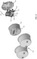
- FIGS. 5A and 5B show an example of a current-transformer structure 500 that can be installed in an electric meter for detecting an arcing condition in the utility box, according to some aspects of the present disclosure.
- the current-transformer structure 500 can be used as the current-transformer structure 306 or 406 shown in FIG. 4 . More specifically, FIG. 5A shows the assembled current-transformer structure 500 and FIG. 5B shows various components of the current-transformer structure 500.
- the current-transformer structure 500 includes a current transformer holder 502, a current transformer 504, an arc detection antenna 508, and a current transformer cover 510.
- the current transformer 504 corresponds to the current transformer 232A or 232B described above with respect to FIG. 2
- the arc detection antenna 508 corresponds to the arc detection antenna 234A or 234B in FIG.2 .
- the current transformer holder 502 can be connected to the current transformer cover 510 to form an enclosed donut-shaped space.
- the current transformer 504 and the arc detection antenna 508 are placed adjacent to each other in this enclosed donut-shaped space and between the current transformer holder 502 and the current transformer cover 510.
- the current transformer cover 510 can be connected or affixed to the transformer holder 502 through, for example, a latch 516 or other mechanical means to securely hold the current transformer 504 and the arc detection antenna 508 within the enclosed space.
- the arc detection antenna 508 is placed between the current transformer 504 and the current transformer cover 510 as shown in FIG. 5B , or, alternatively, the arc detection antenna 508 is placed between the current transformer 504 and the current transformer holder 502. If the arc detection antenna 508 is placed between the current transformer 504 and the current transformer cover 510, the arc detection antenna 508 can be affixed to the top surface of the current transformer 504 through, for example, glue (e.g., epoxy), tape, or other adhesive materials or mechanism means. Alternatively, or additionally, the arc detection antenna 508 may be affixed to the inner surface of the current transformer cover 510 using adhesive materials or mechanical affixing means.
- the arc detection antenna 508 can be affixed to the bottom surface of the current transformer or the inner surface of the current transformer holder 502 using proper affixing means.
- the current transformer cover 510 or the current transformer holder 502 may include a custom housing portion to hold the arc detection antenna 508.
- the leads 506 of the current transformer 504 and the leads 512 of the arc detection antenna 508 are isolated from each other and extend outside the enclosed space of the current-transformer structure 500.
- the leads 506 and the leads 512 can extend outside the current-transformer structure 500 through the same openings 514 as shown in FIG. 5B . In other configurations, they may pass through different openings.
- a single-phase electric meter can include the current-transformer structure presented herein to detect arc detection occurring on the single-phase line.
- a three-phase electric meter can include three current-transformer structures presented herein to detect the arcing conditions in the respective phases.
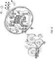
- FIG. 6 shows an example of a baseplate assembly of a three-phase electric meter incorporating three current-transformer structures presented herein.
- only one of the current transformer structures in a multi-phase electric meter is equipped with an arc detection antenna to detect arcing condition.
- the arc detection antenna can be placed in the current transformer structure on the centrally located phase such that the arc detection antenna is more equidistant to all of the blades.
Landscapes
- Physics & Mathematics (AREA)
- General Physics & Mathematics (AREA)
- Engineering & Computer Science (AREA)
- Power Engineering (AREA)
- Measuring Instrument Details And Bridges, And Automatic Balancing Devices (AREA)
- Testing Electric Properties And Detecting Electric Faults (AREA)
- Testing Relating To Insulation (AREA)
- Geophysics And Detection Of Objects (AREA)
- Structure Of Receivers (AREA)
Claims (15)
- Stromzähler (102), der Lichtbögen zwischen dem Stromzähler (102) und einer Zählerbuchse (104) in einem Versorgungskasten (100) detektieren kann, der mit einer Stromleitung (190) verbunden ist, wobei der Stromzähler (102) Folgendes umfasst:
eine Basisplattenanordnung (220), die Folgendes umfasst:einen elektrischen Leiter, der zwei Zählerzungen (103) verbindet, wobei jede der Zählerzungen (103) zum Positionieren in einer entsprechenden Buchsenaufnahme (105) der Zählerbuchse (104) konfiguriert ist, um den Stromzähler (102) elektrisch mit der Zählerbuchse (104) zu verbinden; undeine Stromwandlerstruktur (500), die Folgendes umfasst:einen Stromwandlerhalter (502) und eine Stromwandlerabdeckung (510), die einen geschlossenen Raum bilden;einen Stromwandler (504), der in dem geschlossenen Raum positioniert und induktiv mit dem elektrischen Leiter gekoppelt ist; undeine Bogendetektionsantenne (508), die in dem geschlossenen Raum und neben dem Stromwandler (504) platziert ist, wobei sich Leitungen (512) der Bogendetektionsantenne (508) aus der Stromwandlerstruktur (500) erstrecken; undeine Gehäuseanordnung (304), die zum Koppeln mit der Basisplattenanordnung (220) konfiguriert ist, wobei die Gehäuseanordnung (304) Folgendes umfasst:
eine Leiterplatte (250), die eine Bogendetektionsschaltung (262) beherbergt, die zum Detektieren von Lichtbögen konfiguriert ist, wobei die Leitungen (512) der Bogendetektionsantenne (508) elektrisch mit der Bogendetektionsschaltung (262) verbunden sind. - Stromzähler (102) nach Anspruch 1, wobei die Bogendetektionsantenne (508) mit einem Befestigungsmittel an der Stromwandlerabdeckung (510) oder dem Stromwandlerhalter (502) befestigt ist.
- Stromzähler (102) nach Anspruch 1, wobei die Bogendetektionsantenne (508) mit einem Befestigungsmittel an dem Stromwandler (504) befestigt ist.
- Stromzähler (102) nach Anspruch 1, wobei die Bogendetektionsantenne (508) zwischen dem Stromwandler (504) und der Stromwandlerabdeckung (510) oder zwischen dem Stromwandler (504) und dem Stromwandlerhalter (502) positioniert ist.
- Stromzähler (102) nach Anspruch 1, wobei die Bogendetektionsantenne (508) an einer Stelle innerhalb der Stromwandlerstruktur (500) und zwischen dem Stromwandler (504) und einem Abschnitt der Stromwandlerstruktur (500) einer Innenseite der Basisplattenanordnung (220) zugewandt positioniert ist.
- Stromzähler (102) nach Anspruch 1, wobei die Leiterplatte (250) an einem Ende der Gehäuseanordnung (304) positioniert ist, die einem mit der Basisplattenanordnung (220) gekoppelten Ende gegenüberliegt.
- Stromzähler (102) nach Anspruch 1, wobeidie Leitungen (512) der Bogendetektionsantenne (508) durch eine oder mehrere Öffnungen an dem Stromwandlerhalter (502) oder der Stromwandlerabdeckung (510) aus der Stromwandlerstruktur (500) erstreckt sind;Leitungen (506) des Stromwandlers (504) durch dieselben ein oder mehreren Öffnungen aus der Stromwandlerstruktur (500) erstreckt sind; unddie Leitungen (512) der Bogendetektionsantenne (508) und die Leitungen (506) des Stromwandlers (504) voneinander isoliert sind.
- Stromzähler (102) nach Anspruch 1, wobei die Bogendetektionsantenne (508) eine Schleifenantenne ist.
- Stromwandlerstruktur (500), die Folgendes umfasst:eine Stromwandlerabdeckung (510);einen Stromwandlerhalter (502), der, wenn er mit der Stromwandlerabdeckung verbunden ist, einen geschlossenen Raum bildet;einen Stromwandler (504), der innerhalb des geschlossenen Raums positioniert ist; undeine Bogendetektionsantenne (508), die innerhalb des geschlossenen Raums und neben dem Stromwandler (504) platziert ist, wobei sich Leitungen (512) der Bogendetektionsantenne (508) aus der Stromwandlerstruktur (504) erstrecken; undwobei die Bogendetektionsantenne (508) zwischen dem Stromwandler (504) und der Stromwandlerabdeckung (510) oder zwischen dem Stromwandlerhalter (502) und dem Stromwandler (504) positioniert ist.
- Stromwandlerstruktur (500) nach Anspruch 9, wobei die Bogendetektionsantenne (508) an der Abdeckung des Stromwandlers (504) oder am Stromwandlerhalter (502) befestigt ist.
- Stromwandlerstruktur (500) nach Anspruch 9, wobei die Bogendetektionsantenne (508) am Stromwandler (504) befestigt ist.
- Stromwandlerstruktur (500) nach Anspruch 9, die ferner ein Befestigungsmittel umfasst, das zum Befestigen der Wandlerabdeckung am Wandlerhalter (502) konfiguriert ist, wobei das Befestigungsmittel eine Verriegelung umfasst.
- Stromwandlerstruktur (500) nach Anspruch 9, wobei die Bogendetektionsantenne (508) an einer Stelle innerhalb der Stromwandlerstruktur (500) und zwischen dem Stromwandler (504) und einem Abschnitt der Stromwandlerstruktur (500) einer Innenseite der Basisplatte zugewandt positioniert ist.
- Stromwandlerstruktur (500) nach Anspruch 9, wobeidie Leitungen (512) der Bogendetektionsantenne (508) durch eine oder mehrere Öffnungen an dem Stromwandlerhalter (502) oder der Stromwandlerabdeckung (510) aus der Stromwandlerstruktur (500) erstreckt sind;Leitungen (506) des Stromwandlers (504) durch dieselben ein oder mehreren Öffnungen aus der Stromwandlerstruktur (500) erstreckt sind; unddie Leitungen (512) der Bogendetektionsantenne (508) und die Leitungen des Stromwandlers (504) voneinander isoliert sind.
- Stromwandlerstruktur (500) nach Anspruch 9, wobei die Bogendetektionsantenne (508) eine Schleifenantenne ist.
Applications Claiming Priority (2)
| Application Number | Priority Date | Filing Date | Title |
|---|---|---|---|
| US16/776,833 US11444444B2 (en) | 2020-01-30 | 2020-01-30 | Arc detection antenna in electric meter systems |
| PCT/US2021/015092 WO2021154728A1 (en) | 2020-01-30 | 2021-01-26 | Arc detection antenna in electric meter systems |
Publications (2)
| Publication Number | Publication Date |
|---|---|
| EP4097490A1 EP4097490A1 (de) | 2022-12-07 |
| EP4097490B1 true EP4097490B1 (de) | 2025-03-05 |
Family
ID=74626260
Family Applications (1)
| Application Number | Title | Priority Date | Filing Date |
|---|---|---|---|
| EP21705837.9A Active EP4097490B1 (de) | 2020-01-30 | 2021-01-26 | Lichtbogendetektionsantenne in elektrischen messgerätsystemen |
Country Status (7)
| Country | Link |
|---|---|
| US (1) | US11444444B2 (de) |
| EP (1) | EP4097490B1 (de) |
| JP (1) | JP7789003B2 (de) |
| AU (1) | AU2021213104A1 (de) |
| BR (1) | BR112022014059A2 (de) |
| CA (1) | CA3167732A1 (de) |
| WO (1) | WO2021154728A1 (de) |
Families Citing this family (3)
| Publication number | Priority date | Publication date | Assignee | Title |
|---|---|---|---|---|
| US11226357B2 (en) * | 2019-09-27 | 2022-01-18 | Landis+Gyr Innovations, Inc. | Electrical arc detection for electric meter socket connections |
| GB202304435D0 (en) | 2023-03-27 | 2023-05-10 | Landis & Gyr Technology Inc | Arc sensor antenna |
| WO2025198591A1 (en) * | 2024-03-21 | 2025-09-25 | Sensata Technologies, Inc. | Wireless arc detection in an electrical system |
Family Cites Families (21)
| Publication number | Priority date | Publication date | Assignee | Title |
|---|---|---|---|---|
| US2652521A (en) * | 1949-08-22 | 1953-09-15 | Nu Way Corp | Shield for transformer coils |
| US2601250A (en) * | 1951-01-27 | 1952-06-24 | Otis Elevator Co | Safety mechanism for doors |
| JPH0330875U (de) * | 1989-08-02 | 1991-03-26 | ||
| JPH0348327U (de) * | 1989-09-19 | 1991-05-09 | ||
| US5185686A (en) * | 1991-03-28 | 1993-02-09 | Eaton Corporation | Direction sensing arc detection |
| US5185684A (en) | 1991-03-28 | 1993-02-09 | Eaton Corporation | Frequency selective arc detection |
| US5434509A (en) | 1992-07-30 | 1995-07-18 | Blades; Frederick K. | Method and apparatus for detecting arcing in alternating-current power systems by monitoring high-frequency noise |
| US20130243425A1 (en) * | 1996-12-24 | 2013-09-19 | Convergence Wireless, Inc. | Method and apparatus for the zonal transmission of data using building lighting fixtures |
| US7417419B2 (en) * | 2003-02-03 | 2008-08-26 | Landis+Gyr, Inc. | Method and arrangement for connecting electrical components in an electricity meter |
| DE102011006666B4 (de) * | 2011-04-01 | 2013-07-04 | Bender Gmbh & Co. Kg | Vorrichtung zur Isolationsfehlersuche |
| DE102012218504A1 (de) | 2012-10-11 | 2014-04-17 | Bender Gmbh & Co. Kg | Differenzstrom-Überwachungseinrichtung mit Lichtbogenerkennung |
| US9537198B2 (en) * | 2013-10-01 | 2017-01-03 | Telefonaktiebolaget L M Ericsson (Publ) | Wideband impedance transformer |
| EP3072144B1 (de) | 2013-11-22 | 2019-01-09 | Schneider Electric USA, Inc. | Multifunktionsschutzschalter mit einer einzigen prüftaste |
| US20160010442A1 (en) * | 2014-05-12 | 2016-01-14 | Qmast LLC, a Colorado Limited Liability Company | Circulation methodologies and systems for hydrocarbon production from oil shale and oil sands and well-rehabilitation and formational pressurization of conventional hydrocarbon systems |
| CN204116416U (zh) * | 2014-10-31 | 2015-01-21 | 上海金陵智能电表有限公司 | 一种大安培插拔式三相多功能智能电能表的外壳结构及插座结构 |
| GB2537113B (en) * | 2015-04-01 | 2018-05-23 | High Voltage Partial Discharge Ltd | Apparatus and method for monitoring partial discharge |
| US10511157B2 (en) * | 2016-08-29 | 2019-12-17 | Landis+Gyr Innovations, Inc. | Arc detection in electric meter systems |
| CN106771477B (zh) * | 2016-11-28 | 2020-09-01 | 国网福建省电力有限公司 | 大口径高灵敏度的高压直流电缆泄漏电流检测传感器 |
| US11215650B2 (en) * | 2017-02-28 | 2022-01-04 | Veris Industries, Llc | Phase aligned branch energy meter |
| US10578659B2 (en) * | 2017-10-20 | 2020-03-03 | Landis+Gyr Llc | Method and system for hot socket detection and tampering detection in a utility meter |
| US10816580B2 (en) | 2018-01-24 | 2020-10-27 | Landis+Gyr Llc | Electric meter contact arc detector employing dual-purposed inductive components |
-
2020
- 2020-01-30 US US16/776,833 patent/US11444444B2/en active Active
-
2021
- 2021-01-26 BR BR112022014059A patent/BR112022014059A2/pt unknown
- 2021-01-26 WO PCT/US2021/015092 patent/WO2021154728A1/en not_active Ceased
- 2021-01-26 AU AU2021213104A patent/AU2021213104A1/en active Pending
- 2021-01-26 EP EP21705837.9A patent/EP4097490B1/de active Active
- 2021-01-26 JP JP2022546538A patent/JP7789003B2/ja active Active
- 2021-01-26 CA CA3167732A patent/CA3167732A1/en active Pending
Also Published As
| Publication number | Publication date |
|---|---|
| WO2021154728A1 (en) | 2021-08-05 |
| US11444444B2 (en) | 2022-09-13 |
| US20210242675A1 (en) | 2021-08-05 |
| JP7789003B2 (ja) | 2025-12-19 |
| AU2021213104A1 (en) | 2022-09-08 |
| JP2023513074A (ja) | 2023-03-30 |
| CA3167732A1 (en) | 2021-08-05 |
| BR112022014059A2 (pt) | 2022-09-13 |
| EP4097490A1 (de) | 2022-12-07 |
Similar Documents
| Publication | Publication Date | Title |
|---|---|---|
| EP4097490B1 (de) | Lichtbogendetektionsantenne in elektrischen messgerätsystemen | |
| US12520157B2 (en) | Communication enabled circuit breakers | |
| RU2615597C2 (ru) | Комбинированный датчик тока и способ установки упомянутого датчика | |
| US8193803B2 (en) | Current measuring device | |
| US7174261B2 (en) | Power line sensors and systems incorporating same | |
| US6348800B1 (en) | Multi-phase ground fault current sensor system | |
| JP5976121B2 (ja) | 電源開閉装置用小型接続システム | |
| CN102854363B (zh) | 测量装置以及包括该测量装置的电气设备单元 | |
| US20140132249A1 (en) | Mixed current sensor and method for fitting said sensor | |
| EP2807664B1 (de) | Kombinationstransformator für ein stromsystem | |
| CN105044480A (zh) | 测量电气设备中流动电流的至少一个电变量的装置 | |
| KR102581728B1 (ko) | 누전 및 과열방지 경보형 에너지하베스팅 모듈을 구비한 수배전반 | |
| JPWO2013057925A1 (ja) | 電気機器の状態監視装置 | |
| EP4643142A1 (de) | Lichtbogenerkennungsantenne | |
| US20250341547A1 (en) | Residual current operated device with all-current sensitive detection of differential currents and charging plug, in-cable control box, charging cable and charger therewith | |
| US11249136B2 (en) | Switch with a signal generating unit and a self-test unit | |
| FI122736B (fi) | Laite energiankulutuksen mittaamiseksi sekä elektroniikkakomponentti ja niiden käytöt | |
| KR20010027246A (ko) | 교류 전류센서 및 이것을 내장하는 전력기기 | |
| CN102651293A (zh) | 断路器 | |
| JPH0545384A (ja) | 変流器 | |
| RU176289U1 (ru) | Электрический полюс автоматического выключателя | |
| CN121773494A (zh) | 配线用断路器的电子跳闸部 | |
| EP2394179A1 (de) | Strommess-nebenschluss | |
| JP2020112404A (ja) | 高圧導体の状態表示装置 |
Legal Events
| Date | Code | Title | Description |
|---|---|---|---|
| STAA | Information on the status of an ep patent application or granted ep patent |
Free format text: STATUS: UNKNOWN |
|
| STAA | Information on the status of an ep patent application or granted ep patent |
Free format text: STATUS: THE INTERNATIONAL PUBLICATION HAS BEEN MADE |
|
| PUAI | Public reference made under article 153(3) epc to a published international application that has entered the european phase |
Free format text: ORIGINAL CODE: 0009012 |
|
| STAA | Information on the status of an ep patent application or granted ep patent |
Free format text: STATUS: REQUEST FOR EXAMINATION WAS MADE |
|
| 17P | Request for examination filed |
Effective date: 20220715 |
|
| AK | Designated contracting states |
Kind code of ref document: A1 Designated state(s): AL AT BE BG CH CY CZ DE DK EE ES FI FR GB GR HR HU IE IS IT LI LT LU LV MC MK MT NL NO PL PT RO RS SE SI SK SM TR |
|
| DAV | Request for validation of the european patent (deleted) | ||
| DAX | Request for extension of the european patent (deleted) | ||
| P01 | Opt-out of the competence of the unified patent court (upc) registered |
Effective date: 20230517 |
|
| RAP1 | Party data changed (applicant data changed or rights of an application transferred) |
Owner name: LANDIS+GYR TECHNOLOGY, INC. |
|
| STAA | Information on the status of an ep patent application or granted ep patent |
Free format text: STATUS: EXAMINATION IS IN PROGRESS |
|
| 17Q | First examination report despatched |
Effective date: 20240325 |
|
| GRAP | Despatch of communication of intention to grant a patent |
Free format text: ORIGINAL CODE: EPIDOSNIGR1 |
|
| STAA | Information on the status of an ep patent application or granted ep patent |
Free format text: STATUS: GRANT OF PATENT IS INTENDED |
|
| INTG | Intention to grant announced |
Effective date: 20240903 |
|
| GRAS | Grant fee paid |
Free format text: ORIGINAL CODE: EPIDOSNIGR3 |
|
| GRAA | (expected) grant |
Free format text: ORIGINAL CODE: 0009210 |
|
| STAA | Information on the status of an ep patent application or granted ep patent |
Free format text: STATUS: THE PATENT HAS BEEN GRANTED |
|
| AK | Designated contracting states |
Kind code of ref document: B1 Designated state(s): AL AT BE BG CH CY CZ DE DK EE ES FI FR GB GR HR HU IE IS IT LI LT LU LV MC MK MT NL NO PL PT RO RS SE SI SK SM TR |
|
| REG | Reference to a national code |
Ref country code: GB Ref legal event code: FG4D |
|
| REG | Reference to a national code |
Ref country code: CH Ref legal event code: EP |
|
| REG | Reference to a national code |
Ref country code: IE Ref legal event code: FG4D |
|
| REG | Reference to a national code |
Ref country code: DE Ref legal event code: R096 Ref document number: 602021027125 Country of ref document: DE |
|
| REG | Reference to a national code |
Ref country code: NL Ref legal event code: FP |
|
| PG25 | Lapsed in a contracting state [announced via postgrant information from national office to epo] |
Ref country code: RS Free format text: LAPSE BECAUSE OF FAILURE TO SUBMIT A TRANSLATION OF THE DESCRIPTION OR TO PAY THE FEE WITHIN THE PRESCRIBED TIME-LIMIT Effective date: 20250605 |
|
| PG25 | Lapsed in a contracting state [announced via postgrant information from national office to epo] |
Ref country code: FI Free format text: LAPSE BECAUSE OF FAILURE TO SUBMIT A TRANSLATION OF THE DESCRIPTION OR TO PAY THE FEE WITHIN THE PRESCRIBED TIME-LIMIT Effective date: 20250305 |
|
| PG25 | Lapsed in a contracting state [announced via postgrant information from national office to epo] |
Ref country code: ES Free format text: LAPSE BECAUSE OF FAILURE TO SUBMIT A TRANSLATION OF THE DESCRIPTION OR TO PAY THE FEE WITHIN THE PRESCRIBED TIME-LIMIT Effective date: 20250305 |
|
| REG | Reference to a national code |
Ref country code: LT Ref legal event code: MG9D |
|
| PG25 | Lapsed in a contracting state [announced via postgrant information from national office to epo] |
Ref country code: NO Free format text: LAPSE BECAUSE OF FAILURE TO SUBMIT A TRANSLATION OF THE DESCRIPTION OR TO PAY THE FEE WITHIN THE PRESCRIBED TIME-LIMIT Effective date: 20250605 |
|
| PG25 | Lapsed in a contracting state [announced via postgrant information from national office to epo] |
Ref country code: HR Free format text: LAPSE BECAUSE OF FAILURE TO SUBMIT A TRANSLATION OF THE DESCRIPTION OR TO PAY THE FEE WITHIN THE PRESCRIBED TIME-LIMIT Effective date: 20250305 |
|
| PG25 | Lapsed in a contracting state [announced via postgrant information from national office to epo] |
Ref country code: LV Free format text: LAPSE BECAUSE OF FAILURE TO SUBMIT A TRANSLATION OF THE DESCRIPTION OR TO PAY THE FEE WITHIN THE PRESCRIBED TIME-LIMIT Effective date: 20250305 |
|
| PG25 | Lapsed in a contracting state [announced via postgrant information from national office to epo] |
Ref country code: GR Free format text: LAPSE BECAUSE OF FAILURE TO SUBMIT A TRANSLATION OF THE DESCRIPTION OR TO PAY THE FEE WITHIN THE PRESCRIBED TIME-LIMIT Effective date: 20250606 Ref country code: BG Free format text: LAPSE BECAUSE OF FAILURE TO SUBMIT A TRANSLATION OF THE DESCRIPTION OR TO PAY THE FEE WITHIN THE PRESCRIBED TIME-LIMIT Effective date: 20250305 |
|
| REG | Reference to a national code |
Ref country code: AT Ref legal event code: MK05 Ref document number: 1773361 Country of ref document: AT Kind code of ref document: T Effective date: 20250305 |
|
| PG25 | Lapsed in a contracting state [announced via postgrant information from national office to epo] |
Ref country code: SE Free format text: LAPSE BECAUSE OF FAILURE TO SUBMIT A TRANSLATION OF THE DESCRIPTION OR TO PAY THE FEE WITHIN THE PRESCRIBED TIME-LIMIT Effective date: 20250305 |
|
| PG25 | Lapsed in a contracting state [announced via postgrant information from national office to epo] |
Ref country code: SM Free format text: LAPSE BECAUSE OF FAILURE TO SUBMIT A TRANSLATION OF THE DESCRIPTION OR TO PAY THE FEE WITHIN THE PRESCRIBED TIME-LIMIT Effective date: 20250305 |
|
| PG25 | Lapsed in a contracting state [announced via postgrant information from national office to epo] |
Ref country code: PT Free format text: LAPSE BECAUSE OF FAILURE TO SUBMIT A TRANSLATION OF THE DESCRIPTION OR TO PAY THE FEE WITHIN THE PRESCRIBED TIME-LIMIT Effective date: 20250707 |
|
| PG25 | Lapsed in a contracting state [announced via postgrant information from national office to epo] |
Ref country code: IT Free format text: LAPSE BECAUSE OF FAILURE TO SUBMIT A TRANSLATION OF THE DESCRIPTION OR TO PAY THE FEE WITHIN THE PRESCRIBED TIME-LIMIT Effective date: 20250305 Ref country code: PL Free format text: LAPSE BECAUSE OF FAILURE TO SUBMIT A TRANSLATION OF THE DESCRIPTION OR TO PAY THE FEE WITHIN THE PRESCRIBED TIME-LIMIT Effective date: 20250305 |
|
| PG25 | Lapsed in a contracting state [announced via postgrant information from national office to epo] |
Ref country code: AT Free format text: LAPSE BECAUSE OF FAILURE TO SUBMIT A TRANSLATION OF THE DESCRIPTION OR TO PAY THE FEE WITHIN THE PRESCRIBED TIME-LIMIT Effective date: 20250305 |
|
| PG25 | Lapsed in a contracting state [announced via postgrant information from national office to epo] |
Ref country code: EE Free format text: LAPSE BECAUSE OF FAILURE TO SUBMIT A TRANSLATION OF THE DESCRIPTION OR TO PAY THE FEE WITHIN THE PRESCRIBED TIME-LIMIT Effective date: 20250305 Ref country code: CZ Free format text: LAPSE BECAUSE OF FAILURE TO SUBMIT A TRANSLATION OF THE DESCRIPTION OR TO PAY THE FEE WITHIN THE PRESCRIBED TIME-LIMIT Effective date: 20250305 |
|
| PG25 | Lapsed in a contracting state [announced via postgrant information from national office to epo] |
Ref country code: RO Free format text: LAPSE BECAUSE OF FAILURE TO SUBMIT A TRANSLATION OF THE DESCRIPTION OR TO PAY THE FEE WITHIN THE PRESCRIBED TIME-LIMIT Effective date: 20250305 |
|
| PG25 | Lapsed in a contracting state [announced via postgrant information from national office to epo] |
Ref country code: SK Free format text: LAPSE BECAUSE OF FAILURE TO SUBMIT A TRANSLATION OF THE DESCRIPTION OR TO PAY THE FEE WITHIN THE PRESCRIBED TIME-LIMIT Effective date: 20250305 |
|
| PG25 | Lapsed in a contracting state [announced via postgrant information from national office to epo] |
Ref country code: IS Free format text: LAPSE BECAUSE OF FAILURE TO SUBMIT A TRANSLATION OF THE DESCRIPTION OR TO PAY THE FEE WITHIN THE PRESCRIBED TIME-LIMIT Effective date: 20250705 |
|
| REG | Reference to a national code |
Ref country code: DE Ref legal event code: R097 Ref document number: 602021027125 Country of ref document: DE |
|
| PLBE | No opposition filed within time limit |
Free format text: ORIGINAL CODE: 0009261 |
|
| STAA | Information on the status of an ep patent application or granted ep patent |
Free format text: STATUS: NO OPPOSITION FILED WITHIN TIME LIMIT |
|
| PG25 | Lapsed in a contracting state [announced via postgrant information from national office to epo] |
Ref country code: DK Free format text: LAPSE BECAUSE OF FAILURE TO SUBMIT A TRANSLATION OF THE DESCRIPTION OR TO PAY THE FEE WITHIN THE PRESCRIBED TIME-LIMIT Effective date: 20250305 |
|
| REG | Reference to a national code |
Ref country code: CH Ref legal event code: L10 Free format text: ST27 STATUS EVENT CODE: U-0-0-L10-L00 (AS PROVIDED BY THE NATIONAL OFFICE) Effective date: 20260114 |
|
| REG | Reference to a national code |
Ref country code: CH Ref legal event code: U11 Free format text: ST27 STATUS EVENT CODE: U-0-0-U10-U11 (AS PROVIDED BY THE NATIONAL OFFICE) Effective date: 20260201 |
|
| 26N | No opposition filed |
Effective date: 20251208 |
|
| PGFP | Annual fee paid to national office [announced via postgrant information from national office to epo] |
Ref country code: NL Payment date: 20260121 Year of fee payment: 6 |
|
| PGFP | Annual fee paid to national office [announced via postgrant information from national office to epo] |
Ref country code: GB Payment date: 20260123 Year of fee payment: 6 |
|
| PGFP | Annual fee paid to national office [announced via postgrant information from national office to epo] |
Ref country code: DE Payment date: 20260121 Year of fee payment: 6 |
|
| PGFP | Annual fee paid to national office [announced via postgrant information from national office to epo] |
Ref country code: FR Payment date: 20260123 Year of fee payment: 6 |
|
| PGFP | Annual fee paid to national office [announced via postgrant information from national office to epo] |
Ref country code: TR Payment date: 20260122 Year of fee payment: 6 |
|
| PGFP | Annual fee paid to national office [announced via postgrant information from national office to epo] |
Ref country code: CH Payment date: 20260201 Year of fee payment: 6 |