EP4097000B1 - Rettungsgürtel - Google Patents
Rettungsgürtel Download PDFInfo
- Publication number
- EP4097000B1 EP4097000B1 EP21702015.5A EP21702015A EP4097000B1 EP 4097000 B1 EP4097000 B1 EP 4097000B1 EP 21702015 A EP21702015 A EP 21702015A EP 4097000 B1 EP4097000 B1 EP 4097000B1
- Authority
- EP
- European Patent Office
- Prior art keywords
- wearer
- life preserver
- main body
- body portion
- neck
- Prior art date
- Legal status (The legal status is an assumption and is not a legal conclusion. Google has not performed a legal analysis and makes no representation as to the accuracy of the status listed.)
- Active
Links
Images




Classifications
-
- B—PERFORMING OPERATIONS; TRANSPORTING
- B63—SHIPS OR OTHER WATERBORNE VESSELS; RELATED EQUIPMENT
- B63C—LAUNCHING, HAULING-OUT, OR DRY-DOCKING OF VESSELS; LIFE-SAVING IN WATER; EQUIPMENT FOR DWELLING OR WORKING UNDER WATER; MEANS FOR SALVAGING OR SEARCHING FOR UNDERWATER OBJECTS
- B63C9/00—Life-saving in water
- B63C9/08—Life-buoys, e.g. rings; Life-belts, jackets, suits, or the like
- B63C9/081—Life-buoys, e.g. rings; Life-belts, jackets, suits, or the like having compartments comprising elements which are filled with gas by deployment, e.g. sponge-like elements
-
- B—PERFORMING OPERATIONS; TRANSPORTING
- B63—SHIPS OR OTHER WATERBORNE VESSELS; RELATED EQUIPMENT
- B63C—LAUNCHING, HAULING-OUT, OR DRY-DOCKING OF VESSELS; LIFE-SAVING IN WATER; EQUIPMENT FOR DWELLING OR WORKING UNDER WATER; MEANS FOR SALVAGING OR SEARCHING FOR UNDERWATER OBJECTS
- B63C9/00—Life-saving in water
- B63C9/08—Life-buoys, e.g. rings; Life-belts, jackets, suits, or the like
- B63C9/13—Life-buoys, e.g. rings; Life-belts, jackets, suits, or the like attachable to body member, e.g. arm, neck, head or waist
- B63C9/15—Life-buoys, e.g. rings; Life-belts, jackets, suits, or the like attachable to body member, e.g. arm, neck, head or waist having gas-filled compartments
- B63C9/155—Life-buoys, e.g. rings; Life-belts, jackets, suits, or the like attachable to body member, e.g. arm, neck, head or waist having gas-filled compartments inflatable
-
- B—PERFORMING OPERATIONS; TRANSPORTING
- B63—SHIPS OR OTHER WATERBORNE VESSELS; RELATED EQUIPMENT
- B63C—LAUNCHING, HAULING-OUT, OR DRY-DOCKING OF VESSELS; LIFE-SAVING IN WATER; EQUIPMENT FOR DWELLING OR WORKING UNDER WATER; MEANS FOR SALVAGING OR SEARCHING FOR UNDERWATER OBJECTS
- B63C9/00—Life-saving in water
- B63C9/08—Life-buoys, e.g. rings; Life-belts, jackets, suits, or the like
- B63C9/11—Life-buoys, e.g. rings; Life-belts, jackets, suits, or the like covering the torso, e.g. harnesses
- B63C9/125—Life-buoys, e.g. rings; Life-belts, jackets, suits, or the like covering the torso, e.g. harnesses having gas-filled compartments
- B63C9/1255—Life-buoys, e.g. rings; Life-belts, jackets, suits, or the like covering the torso, e.g. harnesses having gas-filled compartments inflatable
-
- B—PERFORMING OPERATIONS; TRANSPORTING
- B63—SHIPS OR OTHER WATERBORNE VESSELS; RELATED EQUIPMENT
- B63C—LAUNCHING, HAULING-OUT, OR DRY-DOCKING OF VESSELS; LIFE-SAVING IN WATER; EQUIPMENT FOR DWELLING OR WORKING UNDER WATER; MEANS FOR SALVAGING OR SEARCHING FOR UNDERWATER OBJECTS
- B63C9/00—Life-saving in water
- B63C9/08—Life-buoys, e.g. rings; Life-belts, jackets, suits, or the like
- B63C9/13—Life-buoys, e.g. rings; Life-belts, jackets, suits, or the like attachable to body member, e.g. arm, neck, head or waist
- B63C2009/133—Life-buoys, e.g. rings; Life-belts, jackets, suits, or the like attachable to body member, e.g. arm, neck, head or waist specially adapted for being attachable to the user's head or neck, e.g. like a cap or collar
Definitions
- the present invention relates to a life preserver.
- life preservers such as lifejackets
- an inflatable main body portion for providing buoyancy for the wearer so that the wearer's head is supported above the surface of the water in order to prevent drowning.
- Lifejackets typically include an opening for the wearer's head and neck.
- Single lobe lifejackets have a single lobe that lies over the wearer's chest and a neck portion that lies behind the wearer's neck, with an aperture for the wearer's head.
- Such lifejackets have the benefit that when inflated the single lobe does not form a channel for water to the wearer's airways. They also have better self-righting characteristics that twin lobe lifejackets.
- to make the lifejacket secure when inflated around the neck the neck aperture must not be too large. Consequently, such lifejackets are difficult to don over the head particularly if wearing a bulky jacket or coat with a hood.
- GB 1 014 214 A discloses a life preserver according to the preamble of claim 1.
- Embodiments of the present invention seek to provide an improved life preserver.
- a life preserver including an inflatable main body portion formed by corresponding front and rear layers of material that are connected around their outer peripheries and which each have an aperture for a wearer's neck, wherein the main body portion further comprises additional layer of material that is connected to the front and rear layers of material around the apertures to form a surface that, upon inflation of the main body portion, encircles the wearer's neck.
- the surface is configured to grip the wearer's neck on inflation, which will tend to prevent the life preserver riding up over the wearer's head.
- the aperture when the life preserver is deflated, can consequently be made larger so that the life preserver is easier to don but which still fits securely around the wearer's neck once inflated.
- the additional layer of material is formed from two joined sheets of material that are configured to lie within and parallel to the corresponding front and rear layers of material prior to inflation of the main body portion.
- the life preserver includes a panel of material mounted on a front surface of the main body portion adjacent to, or partially overlying, the neck aperture for protecting the wearer's airways from water splashes.
- a portion of the panel adjacent to, or partially overlying, the neck aperture is further coupled to the main body portion by a strap arrangement that passes through the neck aperture and is mounted to a rear surface of the main body portion.
- the panel is mounted over a component attached to the main body portion, such as an inflation system for the main body portion and the first and second inflatable lobes. This may prevent damage caused by snagging of the component during movement of the wearer.
- a component attached to the main body portion such as an inflation system for the main body portion and the first and second inflatable lobes. This may prevent damage caused by snagging of the component during movement of the wearer.
- the life preserver includes first and second inflatable lobes extending from the main body portion which are configured to respectively occupy a position on the left and right hand side of the wearer's body when in use.
- Such an arrangement may avoid some of the disadvantages of a conventional twin lobe lifejacket described above.
- the main body portion having an aperture for a wearer's neck from which the first and second inflatable lobes extend may not allow a direct passage between the lobes to the wearer's mouth as this is blocked by the main body portion.
- the provision of the two lobes may provide the life preserver with improved self-righting properties and/or improved height of mouth/face plane angle.
- the life preserver is configured such that at least one of the lobes extends obliquely or perpendicularly with respect to an adjacent surface of the wearer's torso when in use.
- the first and second inflatable lobes may occupy a position on the left and right hand side of the front of the wearer's torso when in use. This may provide the life preserver with improved self-righting properties.
- the first and second inflatable lobes are coupled together at a position spaced apart from the main body portion such that adjacent facing edges of the first and second inflatable lobes abut one another in use, the first and second inflatable lobes moving independently of one another and tending to cause self-righting of the wearer when lying face down in water.
- the first and second inflatable lobes may coupled together by a strap arrangement that also mounts the life preserver to the wearer's waist in use.
- the first and second inflatable lobes may occupy a position on the left and right hand side of the back of the wearer's torso when in use. This may provide improved height of mouth/face plane angle for the wearer.
- the first and second inflatable lobes may coupled together at a position spaced apart from the main body portion so that the first and second inflatable lobes extends obliquely or perpendicularly with respect to the back of the wearer's torso.
- the life preserver includes a first set of the first and second inflatable lobes that occupy the position on the left and right hand side of the front of the wearer's torso when in use and a second set of the first and second inflatable lobes that occupy the position on the left and right hand side of the wearer's back when in use.
- the life preserver may be configured such that the main body portion is formed by corresponding front and rear layers of material that are connected around their outer peripheries and which each have an aperture for the wearer's neck, wherein the main body portion further comprises additional layer of material that is connected to the front and rear layers of material around the apertures in the front and rear layers to form a surface that, upon inflation of the main body portion, encircles the wearer's neck. The surface may grip the wearer's neck on inflation.
- the invention is defined by the independent claim 1.
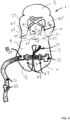
- the life preserver 1 includes a main body portion 3 having an aperture 5 for surrounding a wearer's neck when in use.
- the life preserver 1 further includes first and second inflatable torso buoyancy sections 7 and 9 which form symmetrically disposed lobes that lie on opposite sides of a wearer's torso.
- First, proximal ends of the first and second torso buoyancy sections 7, 9 are joined to the main body portion 3.
- the first and second torso buoyancy sections 7, 9 are preferably integrally formed with the main body portion 3 so that a common inflation chamber extends between the first and second torso buoyancy sections 7, 9 and the main body portion 3.
- the first and second torso buoyancy sections 7, 9 each extend from said first, proximal end to a second end 11, 13, which is a distal end.
- each torso buoyancy section 7, 9 When inflated, each torso buoyancy section 7, 9 may be an elongate member of generally elliptical or oval cross section.
- a waist strap 31 is connected to the bottom surface (the surface facing the wearer's body in use) of each of the buoyancy sections 7 and 9 near the distal ends 11 and 13 thereof and extends around the wearer's waist in use. Ends of the strap 31 are coupled and decoupled from one another by a releasable buckle 33 and shown in figure 2 .
- the first and second torso buoyancy sections 7 and 9 extend in a direction generally obliquely or perpendicularly to the chest of the wearer (rather than lying parallel to chest of the wearer as for a conventional lifejacket). This may be achieved by selecting the a point of attachment 47 and 49, respectively, of the waist strap 31 (see Figure 4 ) to the first torso buoyancy section 7 and to the second torso buoyancy section 9 and the fixed length of waist strap 31 between those points 47 and 49 such that, when the life preserver 1 is inflated the adjacent facing edges 51 and 53 of the first and section buoyancy sections 7 and 9 are pressed together and the first and section buoyancy sections 7 and 9 rotate away from each other, pivoting about the respective points of attachment 47 and 49. This tends to cause the first and second torso buoyancy sections 7 and 9 to extend generally obliquely or perpendicularly to the wearer's chest.
- the length of the strap between the points of attachment 47 and 49 is selected to be less than D so that the first and second torso buoyancy sections 7 and 9 cannot lie parallel to chest of the wearer and are forced to rotate about the points of attachment 47 and 49 so that the first and second torso buoyancy sections 7 and 9 extend in a direction generally obliquely or perpendicularly to the chest of the wearer.
- the arrangement of the torso buoyancy 7 and 9 sections is advantageous in the event that the wearer is lying facing the surface of water, as shown in Figure 8 , which might happen when the wearer is unconscious in an emergency situation.
- the orientation and freedom to independently rotate of the torso buoyancy sections 7 and 9 allows the torso buoyancy sections to move independently of one another to create a rolling effect to aid self-righting, i.e. so that the wearer rotates through 180 degrees, as indicated by arrows 50, so that the wearer faces away from the surface of the water.
- the arrangement of the waist strap 31 and the first and second buoyancy sections 7 and 9 means that the life preserver 1 is unstable in water when the wearer is lying face down in the water and one or other of the torso buoyancy sections 7,9 will move relative to the other, which will cause the life preserver and the wearer to rotate into the desired upwardly facing position.
- the oblique or perpendicular orientation of the torso buoyancy sections 7,9 reduces the overall width of the life preserver 1, providing less restriction to wearer arm movements than a conventional twin lobe lifejacket and so making swimming easier.
- first and second torso buoyancy sections 7,9 are generally elliptical or oval in transverse cross-section, the width dimension being greater than the depth dimension.
- the torso buoyancy sections 7,9 rotate relative to the main body portion 3 so that the larger dimension, instead of overlying and being generally parallel to the chest of the wearer, extends generally perpendicular to or obliquely to the chest of the wearer.
- a wave splash guard panel 15 is attached to the main body portion 3 at a position just below, or partially obscuring, the neck aperture 5.
- the splash guard panel 15 may be generally rectangular or trapezoidal in shape, although other shapes may be used.
- the splash guard panel 15 is attached to the main body portion 3 at least partially along its side edges 17 and 19.
- An inflation cartridge, partially shown at 21 contains compressed gas (e.g. CO 2 ) for inflating the life preserver 1.
- compressed gas e.g. CO 2
- the inflation cartridge 21 can be manually or automatically activated.
- the inflation cartridge 21 is positioned on the front surface of the main body portion 3 and is partially covered by the splash guard panel 15, which reduces the likelihood of the inflation cartridge 21 being caught on another object and causing damage to the life preserver 1 during evacuation or other movements of the wearer.
- the life preserver 1 is also inflatable by a mouth-operable inflator 23 to allow manual inflation in the event of failure of the inflation cartridge 21 or to top up the inflation pressure.
- a non-return valve and a closure cap may prevent water flowing down the inflator 23 and into the inflation chamber of the life preserver 1.
- the inflator 23 passes through an opening in the splash guard panel 15 and lies over the top of the splash guard panel 15 so that is it easily accessible to the wearer.
- the upper edge 55 of the splash guard panel 15 is connected to opposite outer edges 57 and 59 of the main body portion 3 by splash guard panel straps 61 and 63 which extend over the rear surface of the life preserver 1(facing the wearer's body in use).
- the straps 61 and 63 may be connected to the panel 15 along a line 65 extending downwardly from the upper edge 55 of the panel 15, and generally perpendicularly to the upper edge 55 of the panel 15, for a distance approximately equal to the width of the straps 61 and 63.
- connection between the straps 61 and 63 tends to lift the splash guard panel 15 upwards towards the wearer's mouth when the life preserver 1 is inflated and may also tend to fold the outer edges 57 and 59 of the main body portion 3 so that they extend generally obliquely or parallel to the surface of the chest of the wearer and so have a similar orientation to the torso buoyancy sections 7 and 9 and the neck buoyancy sections 35 and 37.
- the splash guard panel straps 61 and 63 when the life preserver 1 is inflated, form surface 64 which will be positioned against the wearer's chin in use, to provide a support for the chin and to tend to close the wearer's mouth.
- the life preserver 1 may also be provided with a whistle 25 and a light 27. As shown in figure 1 , reflective tape 73, to help the wearer be seen, may be provided at various positions on the life preserver 1.
- the main body portion 3 extends behind the wearer's neck and is provided with first and section neck buoyancy sections 35 and 37 which form symmetrically disposed lobes that extend above and behind the wearer's shoulders in use.
- the first and second neck buoyancy sections 35 and 37 are preferably integrally formed with the main body portion 3 (and the torso buoyancy sections 7 and 9) so that a single inflation chamber exists within the first and second neck buoyancy sections 35 and 37 and the main body portion 3 (and the torso buoyancy sections 7 and 9).
- each neck buoyancy section 35 and 37 When inflated, each neck buoyancy section 35 and 37 may be an elongate member of generally elliptical or oval cross section.
- the first and section neck buoyancy sections 35 and 37 in use, extend obliquely or generally perpendicularly to the surface of the wearer's back to provide the desired face plane angle and height of mouth (to be described in more detail later with reference to figure 7 ).
- the orientation of the first and second neck buoyancy portions 35 and 37 is provided by a strap arrangement.
- a first strap 39 is connected to the free, distal end 41 of the first neck buoyancy section and a second strap 43 connected to the free, distal end 45 of the second neck buoyancy section 37.
- the first strap 39 is connected to the proximal end of the second neck buoyancy section 37 where this meets the main body portion 3.
- the second strap 43 is connected to the upper part of the first neck buoyancy section 35 where this meets the main body portion 3.
- the first and second neck buoyancy sections 35 and 37 may be pulled into the orientation shown when the life preserver 1 is inflated.
- the straps 39 and 43 may be connected to one another at the point where they cross over.
- the strap arrangement may comprise a single strap which connects the free, distal ends 41 and 45 of the first and second neck buoyancy sections 35 and 37 directly.
- first and second neck buoyancy sections 35 and 37 are generally elliptical or oval in transverse cross-section, the width dimension being greater than the depth dimension.
- the first and second neck buoyancy sections 35 and 37 rotate relative to the main body portion 3 so that the larger dimension, instead of being generally parallel to the back of the wearer, extends generally perpendicular to or obliquely to the back of the wearer.
- a back strap 67 shown by dashed lines 67, may be provided which connects the main body portion 3 at a position behind the wearer's neck to the waist strap 31 and which extends generally in a direction along the wearer's spine.
- Such a strap 67 may be particularly useful to ensure that the life preserver 1 fits securely to a smaller wearer.
- the waist belt 31, as shown in figure 4 may be provided with a pocket 69 that contains a floating "buddy line” that allows survivors to link themselves in the water for safety.
- the waist belt 31 may also include a lifting becket 71, as shown in figures 1 and 4 ) which allows the wearer to be lifted from the water.
- the main body portion 3 is formed from two panels of coated fabric (typically a nylon or polyester coated with a polymer such as polyurethane), having the shape shown at 80 in figure 5 .
- Two such panels 80 are welded or glued (or otherwise attached) together around the periphery as shown at 82 in figure 5 .
- the splash guard panel 15 is formed by attaching the panel shown at 84 to the front one of the panels 80 at an appropriate position.
- the splash guard 15 straps 61 and 63 may be formed from a single piece of material as shown at 86.
- an additional neck section 87 is provided which, like the main body portion 3 is formed of two panels 88 of coated fabric that are welded or glued (or otherwise attached) together around the periphery as shown at 90.
- the additional neck section 87 has an aperture 92 which corresponds in shape to the neck aperture 5 of the main body portion 3.
- the additional neck section 87 is positioned between the two panels 80 of the main body portion 3 so that its aperture 92 corresponds in orientation to the aperture 5 of the main body portion 3 (i.e. inverted from the orientation shown in figure 5 ).
- the lower one of the panels 80 of the main body portion 3 is welded or glued (or otherwise attached) to the lower one of the panels 88 of the additional neck section 87 around the periphery of the apertures 5 and 92, as indicated at 94.
- the upper one of the panels 80 of the main body portion 3 and the upper one of the panels 88 of the additional neck section 87 are welded or glued (or otherwise attached) together around the periphery of the apertures 5, 92 as shown at 94.
- the welds (or other types of connections) 82, 90 and 94 create a fluid-tight chamber for the life preserver 1 to allow it to be inflated.
- the lower and upper panels 80 of the main body portion are not directly connected to each other around the aperture 5 but instead have the additional neck section 87 as an intermediate element. This allows the distance between the upper and lower panels 80 of the main body portion 3 to increase when the life preserver 1 is inflated, creating a wall which extends against and around and grips the wearer's neck.
- the wall is formed by the panels 88 of the additional neck section 87 moving away from one another due to inflation so that they form an approximately cyclical wall around the wearer's neck.
- Figures 6A, 6B and 6C are cross sections taken along the line A-A in figure 2 .
- Figure 6A shows the arrangement of the additional neck section 87 within the main body portion 3 when the life preserver is in the generally deflated state.
- Figure 6C shows the configuration when the life preserver 1 is fully inflated.
- the panels 88 of the additional neck section 87 in the fully inflated state, form a generally cyclical wall that extends around the wearer's neck and exerts gentle pressure against the neck, as shown by the arrows 96.
- Such an arrangement allows the life preserver unit to be securely and comfortably positioned around the wearer's neck when inflated, but allows the neck aperture 5 (and 92) to be large enough to allow easy donning even when the wearer is wearing a bulky jacket or coat with a hood.
- the additional neck section 87 may be formed from a single panel.
- Figure 7 shows the mouth freeboard (the distance that the mouth of the wearer lies above the surface above the water at A).
- Figure 7 also shows the face plane angle at B.
- the arrangement of the neck buoyancy sections 35 and 37 provides additional buoyancy at the neck of the wearer, as indicated by the arrow C, which tends to increase the mouth freeboard A and also gives a face plane angle of at least 40 degrees to the water surface.
- the additional neck section 87 may be provided in a life preserver without the torso buoyancy sections 7 and 9 and/or the neck buoyancy sections 35 and 37.
- the torso buoyancy sections 7 and 9 and/or the neck buoyancy sections 35 and 37 may be provided in a life preserver without the additional neck section 87.
- the splash guard panel 15 may be provided in a life preserver without the torso buoyancy sections 7 and 9 and/or the neck buoyancy sections 35 and 37. It should also be appreciated that the torso buoyancy sections 7 and 9 and/or the neck buoyancy sections 35 and 37 may be provided in a life preserver without the splash guard panel 15. It should further be appreciated that the splash guard panel 15 may be provided in a life preserver without the additional neck section 87. It should also be appreciated that the additional neck section 87 may be provided in a life preserver without the splash guard panel 15.
Landscapes
- Engineering & Computer Science (AREA)
- Mechanical Engineering (AREA)
- Ocean & Marine Engineering (AREA)
- Professional, Industrial, Or Sporting Protective Garments (AREA)
- Organic Low-Molecular-Weight Compounds And Preparation Thereof (AREA)
Claims (14)
- Rettungsgürtel, einschließlich eines aufblasbaren Hauptkörperabschnitts (3), der aus einer entsprechenden vorderen und einer hinteren Materialschicht (80) gebildet ist, die an ihren Außenrändern (82) verbunden sind und die jeweils eine Apertur (5) für einen Hals eines Trägers haben, wobei der Hauptkörperabschnitt (3) ferner eine zusätzliche Materialschicht (87) umfasst, die mit der vorderen und der hinteren Materialschicht (80) um die Aperturen (5) verbunden ist, um eine Oberfläche zu bilden, die beim Aufblasen des Hauptkörperabschnitts (3) den Hals des Trägers umgibt, wobei die Oberfläche so konfiguriert ist, dass sie den Hals des Trägers beim Aufblasen festhält, und dadurch gekennzeichnet ist, dass die zusätzliche Materialschicht (87) aus zwei miteinander verbundenen Materialbahnen (88) gebildet ist, die so konfiguriert sind, dass sie vor dem Aufblasen des Hauptkörperabschnitts (3) innerhalb und parallel zu der entsprechenden vorderen und der hinteren Materialschicht (80) liegen.
- Rettungsgürtel nach Anspruch 1, einschließlich einer Platte (15) aus Material, die an einer Vorderfläche des Hauptkörperabschnitts (3) benachbart mit oder teilweise über der Halsapertur (5) montiert ist, um die Atemwege des Trägers vor Wasserspritzern zu schützen.
- Rettungsgürtel nach Anspruch 2, wobei ein Abschnitt der Platte (15), der benachbart mit der Halsapertur (5) ist oder teilweise darüber liegt, ferner durch eine Riemenanordnung (61, 63) mit dem Hauptkörperabschnitt (3) gekoppelt ist, die durch die Halsapertur (5) verläuft und an einer hinteren Oberfläche des Hauptkörperabschnitts (5) montiert ist.
- Rettungsgürtel nach Anspruch 2 oder 3, wobei die Platte (15) über einer Komponente (23) montiert ist, die an dem Hauptkörperabschnitt (3) befestigt ist, wie ein Aufblassystem für den Hauptkörperabschnitt (3).
- Rettungsgürtel nach einem der Ansprüche 1 bis 4, einschließlich eines ersten und eines zweiten aufblasbaren Lappens (7, 9), die sich von dem Hauptkörperabschnitt (3) erstrecken und so konfiguriert sind, dass sie jeweils eine Position auf der linken und der rechten Seite des Körpers des Trägers einnehmen, wenn sie verwendet werden.
- Rettungsgürtel nach Anspruch 5, wobei der Rettungsgürtel so konfiguriert ist, dass sich mindestens einer der Lappen (7, 9) schräg oder senkrecht in Bezug auf eine benachbarte Oberfläche des Rumpfes des Trägers erstreckt, wenn er verwendet wird.
- Rettungsgürtel nach Anspruch 5 oder 6, wobei der erste und der zweite aufblasbare Lappen (7, 9) eine Position auf der linken und der rechten Seite der Vorderseite des Rumpfes des Trägers einnehmen, wenn sie verwendet werden.
- Rettungsgürtel nach Anspruch 7, wobei der erste und der zweite aufblasbare Lappen (7, 9) an einer Position (47, 49) miteinander gekoppelt sind, die von dem Hauptkörperabschnitt (3) derart beabstandet ist, dass benachbarte gegenüberliegende Kanten des ersten und des zweiten aufblasbaren Lappens (7, 9) aneinander stoßen, wenn sie verwendet werden, wobei sich der erste und der zweite aufblasbare Lappen (7, 9) unabhängig voneinander bewegen und dazu neigen, eine Selbstaufrichtung des Trägers zu bewirken, wenn er mit dem Gesicht nach unten im Wasser liegt.
- Rettungsgürtel nach Anspruch 8, wobei der erste und der zweite aufblasbare Lappen (7, 9) durch eine Riemenanordnung (31) miteinander gekoppelt sind, die auch den Rettungsgürtel an der Taille des Trägers montiert, wenn sie verwendet wird.
- Rettungsgürtel nach Anspruch 5 oder 6, wobei der erste und der zweite aufblasbare Lappen (35, 37) eine Position auf der linken und der rechten Seite der Rückseite des Rumpfes des Trägers einnehmen, wenn sie verwendet werden.
- Rettungsgürtel nach Anspruch 10, wobei der erste und der zweite aufblasbare Lappen (35, 37) an einer Position (41, 45) miteinander gekoppelt sind, die von dem Hauptkörperabschnitt (3) beabstandet ist, sodass sich der erste und der zweite aufblasbare Lappen (35, 37) schräg oder senkrecht in Bezug auf den Rücken des Rumpfes des Trägers erstrecken.
- Rettungsgürtel nach Anspruch 7 und 10 und wahlweise nach Anspruch 8, 9 oder 11, einschließlich eines ersten Satzes des ersten und des zweiten aufblasbaren Lappens (7, 9), die die Position auf der linken und der rechten Seite der Vorderseite des Rumpfes des Trägers einnehmen, wenn sie verwendet werden, und eines zweiten Satzes des ersten und des zweiten aufblasbaren Lappens (35, 37), die die Position auf der linken und der rechten Seite der Rückseite des Rumpfes des Trägers einnehmen, wenn sie verwendet werden.
- Rettungsgürtel nach einem der Ansprüche 1 bis 12, wobei die vordere und die hintere Materialschicht (80) an der zusätzlichen Materialschicht (87) um einen Außenrand (94) der Apertur (5) für den Hals des Trägers in der vorderen und der hinteren Materialschicht (80) befestigt sind.
- Rettungsgürtel nach einem der Ansprüche 1 bis 13, wobei die zusätzliche Materialschicht (87) beim Aufblasen des Hauptkörperabschnitts (3) eine allgemein zylindrische Wand um den Hals des Trägers bildet.
Applications Claiming Priority (2)
| Application Number | Priority Date | Filing Date | Title |
|---|---|---|---|
| GB2001111.0A GB2591299B (en) | 2020-01-27 | 2020-01-27 | Life preserver |
| PCT/EP2021/051763 WO2021151894A1 (en) | 2020-01-27 | 2021-01-26 | Life preserver |
Publications (2)
| Publication Number | Publication Date |
|---|---|
| EP4097000A1 EP4097000A1 (de) | 2022-12-07 |
| EP4097000B1 true EP4097000B1 (de) | 2025-02-19 |
Family
ID=69725889
Family Applications (1)
| Application Number | Title | Priority Date | Filing Date |
|---|---|---|---|
| EP21702015.5A Active EP4097000B1 (de) | 2020-01-27 | 2021-01-26 | Rettungsgürtel |
Country Status (7)
| Country | Link |
|---|---|
| US (1) | US20230094472A1 (de) |
| EP (1) | EP4097000B1 (de) |
| AU (1) | AU2021213404A1 (de) |
| DK (1) | DK4097000T3 (de) |
| FI (1) | FI4097000T3 (de) |
| GB (1) | GB2591299B (de) |
| WO (1) | WO2021151894A1 (de) |
Family Cites Families (14)
| Publication number | Priority date | Publication date | Assignee | Title |
|---|---|---|---|---|
| GB647188A (en) * | 1948-08-28 | 1950-12-06 | Frankenstein & Sons Manchester | Improvements in or relating to inflatable body-attachments for marine lifesaving |
| GB679610A (en) * | 1950-03-16 | 1952-09-17 | Rfd Co Ltd | Improvements in inflatable life-jackets |
| GB707289A (en) * | 1953-02-16 | 1954-04-14 | Nat Res Dev | Improvements in inflatable life-jackets |
| GB870877A (en) * | 1959-02-17 | 1961-06-21 | Frankenstein & Sons Manchester | Improvements in or relating to inflatable body-attachments for marine lifesaving |
| GB1014214A (en) * | 1963-05-22 | 1965-12-22 | Frankenstein Group Ltd | Improvements in or relating to inflatable articles |
| FR1377151A (fr) * | 1963-12-10 | 1964-10-31 | Accessoire de sauvetage nautique individuel | |
| GB1503975A (en) * | 1975-11-19 | 1978-03-15 | Rfd Inflatables Ltd | Inflatable lifejackets |
| US4297758A (en) * | 1980-01-28 | 1981-11-03 | Switlik Parachute Company, Inc. | Life preserver of the encapsulated type |
| USRE31305E (en) * | 1980-01-28 | 1983-07-12 | Switlik Parachute Company, Inc. | Life preserver of the encapsulated type |
| GB2162129B (en) * | 1984-05-18 | 1987-08-12 | George Williams | Life jackets |
| DE502006007983D1 (de) * | 2005-10-26 | 2010-11-11 | Bernhardt Appbau Gmbh U Co | Rettungsweste |
| US9366505B2 (en) * | 2011-05-10 | 2016-06-14 | David G. Kent | Maritime ballistic safety carrier |
| CN108248796B (zh) * | 2018-03-09 | 2020-01-17 | 陈俊杰 | 可充气救生衣 |
| CN208393598U (zh) * | 2018-03-09 | 2019-01-18 | 陈俊杰 | 可充气救生衣 |
-
2020
- 2020-01-27 GB GB2001111.0A patent/GB2591299B/en active Active
-
2021
- 2021-01-26 EP EP21702015.5A patent/EP4097000B1/de active Active
- 2021-01-26 WO PCT/EP2021/051763 patent/WO2021151894A1/en not_active Ceased
- 2021-01-26 US US17/759,573 patent/US20230094472A1/en active Pending
- 2021-01-26 FI FIEP21702015.5T patent/FI4097000T3/fi active
- 2021-01-26 DK DK21702015.5T patent/DK4097000T3/da active
- 2021-01-26 AU AU2021213404A patent/AU2021213404A1/en active Pending
Also Published As
| Publication number | Publication date |
|---|---|
| GB2591299B (en) | 2024-01-31 |
| AU2021213404A1 (en) | 2022-08-25 |
| EP4097000A1 (de) | 2022-12-07 |
| WO2021151894A1 (en) | 2021-08-05 |
| FI4097000T3 (fi) | 2025-05-22 |
| GB202001111D0 (en) | 2020-03-11 |
| US20230094472A1 (en) | 2023-03-30 |
| DK4097000T3 (da) | 2025-05-19 |
| GB2591299A (en) | 2021-07-28 |
Similar Documents
| Publication | Publication Date | Title |
|---|---|---|
| US6066016A (en) | Inflatable transportable water craft for survival or recreational applications | |
| US5516233A (en) | Water safety and survival system | |
| US6558082B1 (en) | Combined ballast and signalling device for a personal flotation device | |
| US6530725B1 (en) | Water safety and survival system | |
| US4681552A (en) | Combined life vest device and buoyancy compensator | |
| US20040258481A1 (en) | Personal flotation device with eccentric fixed and mobile ballast and buoyant members | |
| US9067658B2 (en) | Inflatable swim vest | |
| US20040033739A1 (en) | Multi-chambered personal survival device and an orally inflated, flush mounted, hybrid bladder | |
| WO2008083077A1 (en) | Personal flotation device | |
| EP0630336B1 (de) | Verbesserungen an schwimmwesten | |
| CA2503084C (en) | Personal flotation device | |
| US6203246B1 (en) | Break away counter weight assembly with neutralizing buoyancy offset for diver's safety | |
| US6527479B1 (en) | Break away counterweight with neutralizing buoyancy offset for diver's safety | |
| US20230094472A1 (en) | Life preserver | |
| JP4121521B2 (ja) | 救命具 | |
| USRE42238E1 (en) | Combined ballast and signalling device for a personal flotation device | |
| GB2480255A (en) | A lifejacket with an integral chin support | |
| US20030194277A1 (en) | No-lock pneumatic coupler | |
| US11731745B1 (en) | Personal flotation, evacuation and rescue device | |
| JPH08244683A (ja) | 簡易救命具 | |
| CA1145619A (en) | Personal floatation device | |
| EP3867141B1 (de) | Rettungsgürtel | |
| AU710021B2 (en) | Sprayhood | |
| GB2465846A (en) | Lifejacket with chest buoyancy sections adapted to provide improved support in water | |
| US7169001B2 (en) | Life jacket |
Legal Events
| Date | Code | Title | Description |
|---|---|---|---|
| STAA | Information on the status of an ep patent application or granted ep patent |
Free format text: STATUS: UNKNOWN |
|
| STAA | Information on the status of an ep patent application or granted ep patent |
Free format text: STATUS: THE INTERNATIONAL PUBLICATION HAS BEEN MADE |
|
| PUAI | Public reference made under article 153(3) epc to a published international application that has entered the european phase |
Free format text: ORIGINAL CODE: 0009012 |
|
| STAA | Information on the status of an ep patent application or granted ep patent |
Free format text: STATUS: REQUEST FOR EXAMINATION WAS MADE |
|
| 17P | Request for examination filed |
Effective date: 20220809 |
|
| AK | Designated contracting states |
Kind code of ref document: A1 Designated state(s): AL AT BE BG CH CY CZ DE DK EE ES FI FR GB GR HR HU IE IS IT LI LT LU LV MC MK MT NL NO PL PT RO RS SE SI SK SM TR |
|
| DAV | Request for validation of the european patent (deleted) | ||
| DAX | Request for extension of the european patent (deleted) | ||
| GRAP | Despatch of communication of intention to grant a patent |
Free format text: ORIGINAL CODE: EPIDOSNIGR1 |
|
| STAA | Information on the status of an ep patent application or granted ep patent |
Free format text: STATUS: GRANT OF PATENT IS INTENDED |
|
| INTG | Intention to grant announced |
Effective date: 20240918 |
|
| GRAS | Grant fee paid |
Free format text: ORIGINAL CODE: EPIDOSNIGR3 |
|
| GRAA | (expected) grant |
Free format text: ORIGINAL CODE: 0009210 |
|
| STAA | Information on the status of an ep patent application or granted ep patent |
Free format text: STATUS: THE PATENT HAS BEEN GRANTED |
|
| AK | Designated contracting states |
Kind code of ref document: B1 Designated state(s): AL AT BE BG CH CY CZ DE DK EE ES FI FR GB GR HR HU IE IS IT LI LT LU LV MC MK MT NL NO PL PT RO RS SE SI SK SM TR |
|
| REG | Reference to a national code |
Ref country code: GB Ref legal event code: FG4D |
|
| REG | Reference to a national code |
Ref country code: CH Ref legal event code: EP |
|
| REG | Reference to a national code |
Ref country code: IE Ref legal event code: FG4D |
|
| REG | Reference to a national code |
Ref country code: DE Ref legal event code: R096 Ref document number: 602021026339 Country of ref document: DE |
|
| REG | Reference to a national code |
Ref country code: DK Ref legal event code: T3 Effective date: 20250516 |
|
| REG | Reference to a national code |
Ref country code: FI Ref legal event code: FGE |
|
| REG | Reference to a national code |
Ref country code: NL Ref legal event code: MP Effective date: 20250219 |
|
| PG25 | Lapsed in a contracting state [announced via postgrant information from national office to epo] |
Ref country code: RS Free format text: LAPSE BECAUSE OF FAILURE TO SUBMIT A TRANSLATION OF THE DESCRIPTION OR TO PAY THE FEE WITHIN THE PRESCRIBED TIME-LIMIT Effective date: 20250519 |
|
| PG25 | Lapsed in a contracting state [announced via postgrant information from national office to epo] |
Ref country code: PL Free format text: LAPSE BECAUSE OF FAILURE TO SUBMIT A TRANSLATION OF THE DESCRIPTION OR TO PAY THE FEE WITHIN THE PRESCRIBED TIME-LIMIT Effective date: 20250219 |
|
| PG25 | Lapsed in a contracting state [announced via postgrant information from national office to epo] |
Ref country code: ES Free format text: LAPSE BECAUSE OF FAILURE TO SUBMIT A TRANSLATION OF THE DESCRIPTION OR TO PAY THE FEE WITHIN THE PRESCRIBED TIME-LIMIT Effective date: 20250219 |
|
| REG | Reference to a national code |
Ref country code: LT Ref legal event code: MG9D |
|
| PG25 | Lapsed in a contracting state [announced via postgrant information from national office to epo] |
Ref country code: IS Free format text: LAPSE BECAUSE OF FAILURE TO SUBMIT A TRANSLATION OF THE DESCRIPTION OR TO PAY THE FEE WITHIN THE PRESCRIBED TIME-LIMIT Effective date: 20250619 Ref country code: NO Free format text: LAPSE BECAUSE OF FAILURE TO SUBMIT A TRANSLATION OF THE DESCRIPTION OR TO PAY THE FEE WITHIN THE PRESCRIBED TIME-LIMIT Effective date: 20250519 |
|
| PG25 | Lapsed in a contracting state [announced via postgrant information from national office to epo] |
Ref country code: NL Free format text: LAPSE BECAUSE OF FAILURE TO SUBMIT A TRANSLATION OF THE DESCRIPTION OR TO PAY THE FEE WITHIN THE PRESCRIBED TIME-LIMIT Effective date: 20250219 |
|
| PG25 | Lapsed in a contracting state [announced via postgrant information from national office to epo] |
Ref country code: HR Free format text: LAPSE BECAUSE OF FAILURE TO SUBMIT A TRANSLATION OF THE DESCRIPTION OR TO PAY THE FEE WITHIN THE PRESCRIBED TIME-LIMIT Effective date: 20250219 |
|
| PG25 | Lapsed in a contracting state [announced via postgrant information from national office to epo] |
Ref country code: PT Free format text: LAPSE BECAUSE OF FAILURE TO SUBMIT A TRANSLATION OF THE DESCRIPTION OR TO PAY THE FEE WITHIN THE PRESCRIBED TIME-LIMIT Effective date: 20250620 Ref country code: LV Free format text: LAPSE BECAUSE OF FAILURE TO SUBMIT A TRANSLATION OF THE DESCRIPTION OR TO PAY THE FEE WITHIN THE PRESCRIBED TIME-LIMIT Effective date: 20250219 |
|
| PG25 | Lapsed in a contracting state [announced via postgrant information from national office to epo] |
Ref country code: BG Free format text: LAPSE BECAUSE OF FAILURE TO SUBMIT A TRANSLATION OF THE DESCRIPTION OR TO PAY THE FEE WITHIN THE PRESCRIBED TIME-LIMIT Effective date: 20250219 Ref country code: GR Free format text: LAPSE BECAUSE OF FAILURE TO SUBMIT A TRANSLATION OF THE DESCRIPTION OR TO PAY THE FEE WITHIN THE PRESCRIBED TIME-LIMIT Effective date: 20250520 |
|
| REG | Reference to a national code |
Ref country code: AT Ref legal event code: MK05 Ref document number: 1768074 Country of ref document: AT Kind code of ref document: T Effective date: 20250219 |
|
| PG25 | Lapsed in a contracting state [announced via postgrant information from national office to epo] |
Ref country code: SE Free format text: LAPSE BECAUSE OF FAILURE TO SUBMIT A TRANSLATION OF THE DESCRIPTION OR TO PAY THE FEE WITHIN THE PRESCRIBED TIME-LIMIT Effective date: 20250219 |
|
| PG25 | Lapsed in a contracting state [announced via postgrant information from national office to epo] |
Ref country code: SM Free format text: LAPSE BECAUSE OF FAILURE TO SUBMIT A TRANSLATION OF THE DESCRIPTION OR TO PAY THE FEE WITHIN THE PRESCRIBED TIME-LIMIT Effective date: 20250219 |
|
| PG25 | Lapsed in a contracting state [announced via postgrant information from national office to epo] |
Ref country code: AT Free format text: LAPSE BECAUSE OF FAILURE TO SUBMIT A TRANSLATION OF THE DESCRIPTION OR TO PAY THE FEE WITHIN THE PRESCRIBED TIME-LIMIT Effective date: 20250219 |
|
| PG25 | Lapsed in a contracting state [announced via postgrant information from national office to epo] |
Ref country code: EE Free format text: LAPSE BECAUSE OF FAILURE TO SUBMIT A TRANSLATION OF THE DESCRIPTION OR TO PAY THE FEE WITHIN THE PRESCRIBED TIME-LIMIT Effective date: 20250219 Ref country code: CZ Free format text: LAPSE BECAUSE OF FAILURE TO SUBMIT A TRANSLATION OF THE DESCRIPTION OR TO PAY THE FEE WITHIN THE PRESCRIBED TIME-LIMIT Effective date: 20250219 |
|
| PG25 | Lapsed in a contracting state [announced via postgrant information from national office to epo] |
Ref country code: RO Free format text: LAPSE BECAUSE OF FAILURE TO SUBMIT A TRANSLATION OF THE DESCRIPTION OR TO PAY THE FEE WITHIN THE PRESCRIBED TIME-LIMIT Effective date: 20250219 |
|
| PG25 | Lapsed in a contracting state [announced via postgrant information from national office to epo] |
Ref country code: SK Free format text: LAPSE BECAUSE OF FAILURE TO SUBMIT A TRANSLATION OF THE DESCRIPTION OR TO PAY THE FEE WITHIN THE PRESCRIBED TIME-LIMIT Effective date: 20250219 |
|
| REG | Reference to a national code |
Ref country code: DE Ref legal event code: R097 Ref document number: 602021026339 Country of ref document: DE |
|
| PLBE | No opposition filed within time limit |
Free format text: ORIGINAL CODE: 0009261 |
|
| STAA | Information on the status of an ep patent application or granted ep patent |
Free format text: STATUS: NO OPPOSITION FILED WITHIN TIME LIMIT |
|
| 26N | No opposition filed |
Effective date: 20251120 |
|
| PGFP | Annual fee paid to national office [announced via postgrant information from national office to epo] |
Ref country code: DK Payment date: 20260126 Year of fee payment: 6 Ref country code: DE Payment date: 20260128 Year of fee payment: 6 |
|
| PGFP | Annual fee paid to national office [announced via postgrant information from national office to epo] |
Ref country code: FI Payment date: 20260126 Year of fee payment: 6 Ref country code: IT Payment date: 20260121 Year of fee payment: 6 |
|
| PGFP | Annual fee paid to national office [announced via postgrant information from national office to epo] |
Ref country code: FR Payment date: 20260126 Year of fee payment: 6 |