EP4096971B1 - Insassensicherheitssystem für ein kraftfahrzeug sowie verfahren zum betreiben eines solchen insassensicherheitssystems - Google Patents
Insassensicherheitssystem für ein kraftfahrzeug sowie verfahren zum betreiben eines solchen insassensicherheitssystems Download PDFInfo
- Publication number
- EP4096971B1 EP4096971B1 EP21703366.1A EP21703366A EP4096971B1 EP 4096971 B1 EP4096971 B1 EP 4096971B1 EP 21703366 A EP21703366 A EP 21703366A EP 4096971 B1 EP4096971 B1 EP 4096971B1
- Authority
- EP
- European Patent Office
- Prior art keywords
- steering wheel
- wheel rim
- occupant safety
- steering
- safety system
- Prior art date
- Legal status (The legal status is an assumption and is not a legal conclusion. Google has not performed a legal analysis and makes no representation as to the accuracy of the status listed.)
- Active
Links
Images



Classifications
-
- B—PERFORMING OPERATIONS; TRANSPORTING
- B60—VEHICLES IN GENERAL
- B60R—VEHICLES, VEHICLE FITTINGS, OR VEHICLE PARTS, NOT OTHERWISE PROVIDED FOR
- B60R21/00—Arrangements or fittings on vehicles for protecting or preventing injuries to occupants or pedestrians in case of accidents or other traffic risks
- B60R21/02—Occupant safety arrangements or fittings, e.g. crash pads
- B60R21/09—Control elements or operating handles movable from an operative to an out-of-the way position, e.g. pedals, switch knobs, window cranks
-
- B—PERFORMING OPERATIONS; TRANSPORTING
- B60—VEHICLES IN GENERAL
- B60R—VEHICLES, VEHICLE FITTINGS, OR VEHICLE PARTS, NOT OTHERWISE PROVIDED FOR
- B60R21/00—Arrangements or fittings on vehicles for protecting or preventing injuries to occupants or pedestrians in case of accidents or other traffic risks
- B60R21/02—Occupant safety arrangements or fittings, e.g. crash pads
- B60R21/16—Inflatable occupant restraints or confinements designed to inflate upon impact or impending impact, e.g. air bags
- B60R21/23—Inflatable members
- B60R21/231—Inflatable members characterised by their shape, construction or spatial configuration
-
- B—PERFORMING OPERATIONS; TRANSPORTING
- B62—LAND VEHICLES FOR TRAVELLING OTHERWISE THAN ON RAILS
- B62D—MOTOR VEHICLES; TRAILERS
- B62D1/00—Steering controls, i.e. means for initiating a change of direction of the vehicle
- B62D1/02—Steering controls, i.e. means for initiating a change of direction of the vehicle vehicle-mounted
- B62D1/16—Steering columns
- B62D1/18—Steering columns yieldable or adjustable, e.g. tiltable
- B62D1/19—Steering columns yieldable or adjustable, e.g. tiltable incorporating energy-absorbing arrangements, e.g. by being yieldable or collapsible
- B62D1/197—Steering columns yieldable or adjustable, e.g. tiltable incorporating energy-absorbing arrangements, e.g. by being yieldable or collapsible incorporating devices for preventing ingress of the steering column into the passengers space in case of accident
-
- B—PERFORMING OPERATIONS; TRANSPORTING
- B60—VEHICLES IN GENERAL
- B60R—VEHICLES, VEHICLE FITTINGS, OR VEHICLE PARTS, NOT OTHERWISE PROVIDED FOR
- B60R21/00—Arrangements or fittings on vehicles for protecting or preventing injuries to occupants or pedestrians in case of accidents or other traffic risks
- B60R21/02—Occupant safety arrangements or fittings, e.g. crash pads
- B60R21/16—Inflatable occupant restraints or confinements designed to inflate upon impact or impending impact, e.g. air bags
- B60R21/23—Inflatable members
- B60R21/231—Inflatable members characterised by their shape, construction or spatial configuration
- B60R2021/23107—Inflatable members characterised by their shape, construction or spatial configuration the bag being integrated in a multi-bag system
-
- B—PERFORMING OPERATIONS; TRANSPORTING
- B60—VEHICLES IN GENERAL
- B60R—VEHICLES, VEHICLE FITTINGS, OR VEHICLE PARTS, NOT OTHERWISE PROVIDED FOR
- B60R21/00—Arrangements or fittings on vehicles for protecting or preventing injuries to occupants or pedestrians in case of accidents or other traffic risks
- B60R21/02—Occupant safety arrangements or fittings, e.g. crash pads
- B60R21/16—Inflatable occupant restraints or confinements designed to inflate upon impact or impending impact, e.g. air bags
- B60R21/23—Inflatable members
- B60R21/231—Inflatable members characterised by their shape, construction or spatial configuration
- B60R2021/23169—Inflatable members characterised by their shape, construction or spatial configuration specially adapted for knee protection
-
- B—PERFORMING OPERATIONS; TRANSPORTING
- B62—LAND VEHICLES FOR TRAVELLING OTHERWISE THAN ON RAILS
- B62D—MOTOR VEHICLES; TRAILERS
- B62D1/00—Steering controls, i.e. means for initiating a change of direction of the vehicle
- B62D1/02—Steering controls, i.e. means for initiating a change of direction of the vehicle vehicle-mounted
- B62D1/04—Hand wheels
- B62D1/10—Hubs; Connecting hubs to steering columns, e.g. adjustable
Definitions
- the invention relates to an occupant safety system for a motor vehicle, with a steering wheel that can be rotated about a steering axis to change the direction of travel and has a steering wheel rim for manual actuation of the steering wheel, wherein the steering wheel rim can be moved between a steering operating position and an occupant safety position, wherein the steering wheel rim spans a rim plane that extends perpendicular to the steering axis in the steering operating position, wherein the steering wheel rim in its occupant safety position is translationally displaced along the steering axis relative to the steering operating position, wherein a knee gas bag module installed outside the steering wheel is provided, which has a knee gas bag that extends into a space between a dashboard of the motor vehicle and a vehicle occupant when the module is activated.
- the invention also relates to a method for operating such an occupant safety system.
- Passenger safety systems for motor vehicles are a technical challenge, particularly on the driver side.
- Driver-side front gas bag modules are currently often still housed in the hub area of rotating steering wheels. Due to the rotation of the steering wheel, the driver gas bags are essentially rotationally symmetrical and their shape can only be adapted to the vehicle interior to a very limited extent.
- the time interval for providing passenger restraint is extremely short, so that the gas bag must emerge from the hub area of the steering wheel very quickly and unfold quickly. This can, under certain circumstances, lead to an impairment of restraint comfort, especially if a vehicle occupant is very close to the steering wheel when the gas bag module is activated.
- the gas bag module takes up a considerable amount of space in the steering wheel, which significantly limits the design freedom when designing the steering wheel.
- accommodating the driver-side front gas bag module in the steering wheel also results in restrictions with regard to possible interior concepts for motor vehicles with automated driving functions.
- the DE 10 2008 000 546 A1 discloses an occupant safety system with the features in the preamble of claim 1, in which the steering wheel, in the event of activation of the knee gas bag module, is displaced translationally along the steering axis in the direction of a vehicle occupant such that the knee gas bag can unfold unhindered between a dashboard and the occupant.
- the object of the invention is to provide an occupant safety system for a motor vehicle and a method for operating such an occupant safety system, in which a vehicle occupant, in particular a driver of the motor vehicle, is even better protected after a vehicle collision.
- this object is achieved by an occupant safety system of the type mentioned at the outset, in which a knee gas bag module is installed outside the steering wheel, with a knee gas bag which extends into a space between a dashboard of the motor vehicle and a vehicle occupant when the module is activated.
- the knee gas bag module is preferably installed behind the dashboard of the motor vehicle, in particular behind a section of the dashboard which faces a footwell of the motor vehicle. Due to the advantageous position of the steering wheel rim in the occupant safety position, deployment of the knee gas bag is not hindered by the steering wheel, so that effective and reliable protection for the lower extremities of a vehicle occupant is also provided on the driver side.
- the steering wheel rim Compared to the steering operating position, the steering wheel rim is in its occupant safety position According to the invention, it is both translationally displaced along the steering axis (A) and additionally pivoted about a rotation axis such that the rim plane no longer extends perpendicular to the steering axis.
- a pivoting angle of the steering wheel rim from the steering operating position to the occupant safety position is in particular at least 20°.
- the combination of translational movement and swivel movement means that the steering wheel assumes an advantageous position in the occupant safety position of the steering wheel rim, in which the deployment of the gas bag is not hindered and occupant contact with the steering wheel is almost impossible.
- the restraining effect of a driver-side front gas bag is particularly preferably positively influenced by the position of the steering wheel rim in the occupant safety position.
- a front gas bag module installed outside the steering wheel is further provided, wherein the front gas bag module has a front gas bag which, when the module is activated, extends into a space between the steering wheel rim and a vehicle occupant.
- the front gas bag module is installed behind a dashboard of the motor vehicle, in particular behind a section of the dashboard that faces a windshield of the motor vehicle.
- the front gas bag module it would also be conceivable for the front gas bag module to be installed in the roof of the motor vehicle. This results in more design freedom in the steering wheel design and in the interior design of motor vehicles with automated driving functions.
- the steering wheel rim is preferably a closed, all-round steering wheel rim, in particular a circular steering wheel rim. Due to the closed shape, the steering wheel rim is particularly stable and can serve as a reliable support for the front gas bag in its occupant safety position.
- the steering wheel rim is closer to a dashboard in its occupant safety position than in its steering operating position. This increases the distance between the vehicle occupant and the steering wheel rim and thus the deployment space for the front gas bag.
- the axis of rotation extends substantially horizontally through a 9 o'clock position and a 3 o'clock position of the steering wheel rim, wherein the steering wheel rim can be pivoted about the axis of rotation such that in the occupant safety position a 12 o'clock position of the steering wheel rim is closer to a dashboard and a 6 o'clock position of the steering wheel rim is further away from the dashboard than in the steering operating position.
- the side of the steering wheel rim facing him thus pivots upwards and the steering wheel is moved along the steering axis is moved translationally in the direction of the dashboard until the occupant safety position of the steering wheel rim is reached, with the steering wheel rim resting particularly against the dashboard in its occupant safety position.
- the steering wheel enables a front gas bag and/or knee gas bag to be deployed smoothly and also forms a stable bearing on which a front gas bag can be supported in the event of an impact with the vehicle occupant.
- the axis of rotation extends substantially horizontally through a 9 o'clock position and a 3 o'clock position of the steering wheel rim, the steering wheel rim being pivotable about the axis of rotation such that in the occupant safety position a 12 o'clock position of the steering wheel rim is further away from a dashboard and a 6 o'clock position of the steering wheel rim is closer to the dashboard than in the steering operating position.
- the side of the steering wheel rim facing him thus pivots downwards and the steering wheel is displaced translationally along the steering axis in the direction of the dashboard until the occupant safety position of the steering wheel rim is reached, the steering wheel rim in its occupant safety position resting in particular on the dashboard. Even in this occupant safety position, the steering wheel enables a front gas bag and/or knee gas bag to be deployed smoothly.
- the occupant safety system preferably includes an actuator for moving the steering wheel rim from the steering operating position to the occupant safety position.
- This actuator is in particular a pyrotechnic actuator, which has an extremely short reaction time after a collision of the motor vehicle and thus ensures that the steering wheel is quickly moved from the steering operating position to the occupant safety position.
- a pre-tensioned spring element with a similarly short reaction time or an electric motor drive can also be used as the actuator.
- the actuator is designed as an (electric motor) drive for reversibly moving the steering wheel rim between the steering operating position and the occupant safety position.
- an occupant safety system is particularly suitable for vehicles with an automated driving mode. If the motor vehicle is moving in the automated driving mode, the drive can move the steering wheel rim to the occupant safety position in order to give the vehicle occupant more freedom of movement.
- the drive preferably has a slow drive speed for changing the driving mode and a fast drive speed for moving the steering wheel rim in the event of a vehicle collision in manual driving mode.
- a separate, second actuator can alternatively be provided, for example a pyrotechnic actuator.
- the Figures 1 to 3 each schematically illustrate the functionality of an occupant safety system 10 for a motor vehicle 12 according to an embodiment and show snapshots before, during and after a system activation. Analogously, in the Figures 5 to 7 the operation of the occupant safety system 10 according to another embodiment is shown.
- the occupant safety system 10 comprises a steering wheel 14 which can be rotated about a steering axis A to change the direction of travel and has a steering wheel rim 16 for manual actuation of the steering wheel 14.
- the steering wheel rim 16 can be moved between a steering operating position and an occupant safety position, wherein the steering wheel rim 16 spans a rim plane E which extends perpendicular to the steering axis A in the steering operating position.
- the steering operating position allows manual steering operation, in which a vehicle occupant 18 determines a direction of travel of the motor vehicle 12 by turning the steering wheel 14 about the steering axis A.
- the steering wheel rim 16 In its occupant safety position according to the Figures 3 and 7 the steering wheel rim 16 assumes a position that is particularly advantageous in terms of passenger safety in the event of a vehicle collision. Manual steering is no longer possible in this position.
- the steering wheel rim 16 can also be moved into the passenger safety position in an automated driving mode of the motor vehicle 12 in order to give the vehicle passenger 18 more freedom of movement.
- the steering wheel 14 is then already in a position that is advantageous for passenger safety in the event of a vehicle collision in the automated driving mode.
- the steering wheel rim 16 In its passenger safety position, the steering wheel rim 16 is translationally displaced along the steering axis A relative to the steering operating position and is also pivoted about a rotation axis B such that the rim plane E no longer extends perpendicular to the steering axis A.
- the motor vehicle 12 has, for example, a steering shaft 20 for rotatably supporting the steering wheel 14 about the steering axis A, wherein the steering shaft 20 is designed to be telescopic in order to enable a translational displacement of the steering wheel 14.
- the steering wheel 14 has, apart from the steering wheel rim 16, a central steering wheel hub 22 and two steering wheel spokes 24 which connect the steering wheel rim 16 with the steering wheel hub 22.
- a pivoting movement of the steering wheel rim 16 about the axis of rotation B can be realized, for example, by a rotatable mounting of the steering wheel rim 16 on the steering wheel hub 22 or a rotatable mounting of the entire steering wheel 14 on the steering shaft 20, wherein the axis of rotation B extends essentially horizontally through a 9 o'clock position and a 3 o'clock position of the steering wheel rim 16 (see Figure 9 ).
- the occupant safety system 10 also includes an actuator 26 for loading the steering wheel rim 16 from the steering operating position to the occupant safety position.
- the actuator 26 is a pyrotechnic actuator; alternatively, however, a pre-tensioned spring element or an electric motor drive would also be conceivable.
- the actuator 26 can also be designed as a drive for reversibly loading the steering wheel rim 16 in order to move the steering wheel rim 16 into its steering operating position for the manual driving mode and into its occupant safety position for the automated driving mode.
- the actuator 26 preferably ensures both the translational displacement of the steering wheel 14 along the steering axis A and the pivoting movement of the steering wheel rim 16 about the axis of rotation B.
- the actuator 26 can optionally also cause a rotation about the steering axis A in order to move the steering wheel 14 into its neutral position for straight-ahead driving.
- the occupant safety system 10 further comprises an electrical control unit 28, a crash sensor 30 and at least one gas bag module 32, 34 and is operated as follows:
- the crash sensor 30 first detects a collision or an impending collision of the motor vehicle 12 and sends a corresponding sensor signal to the electrical control unit 28.
- the electrical control unit 28 then actuates the actuator 26 and the two gas bag modules 32, 34, with the actuator 26 being actuated earlier than the gas bag modules 32, 34 or simultaneously with the gas bag modules 32, 34.
- the occupant safety system 10 comprises, in accordance with the Figures 1 to 8 a front gas bag module 32 installed outside the steering wheel 14, wherein this front gas bag module 32 has a front gas bag 36 which, when the module is activated, extends into a space between the steering wheel rim 16 and the vehicle occupant 18.
- the front gas bag module 32 is installed behind a dashboard 38 of the motor vehicle 12, in particular behind a section of the dashboard 32 which faces a windshield 40 of the motor vehicle 12.
- Such a front gas bag module 32 has the advantage that when it is deployed, it presses the upper extremities of the vehicle occupant 18 downwards away from the steering wheel rim 16 (see Figures 3 and 7 , arm rotation 33), which has a positive effect on restraint comfort and increases occupant safety in the event of a vehicle collision.
- the occupant safety system 10 further comprises a knee airbag module 34 installed outside the steering wheel 14, wherein this knee airbag module 34 has a knee airbag 42 which, when the module is activated, extends into a space between the vehicle occupant 18 and the dashboard 38 of the motor vehicle 12.
- the knee airbag module 34 is installed behind the dashboard 38 of the motor vehicle 12, in particular behind a section of the dashboard 38 which faces a footwell 44 of the motor vehicle 12.
- occupant safety systems 10' are already known from the prior art which, when a vehicle collision is detected, translationally displace the steering wheel rim 16' in the manner described above.
- the conventional steering wheel rim 16' can still hinder or impair the deployment of the driver's side front gas bag 36' and/or the driver's side knee gas bag 42' even after such a translational displacement towards the dashboard 38'.
- the steering wheel rim 16 is therefore in the embodiment according to the Figures 1 to 3 additionally pivoted about the axis of rotation B such that in the occupant safety position a 12 o'clock position of the steering wheel rim 16 is closer to the dashboard 38 and a 6 o'clock position of the steering wheel rim 16 is further away from the dashboard 38 than in the steering operating position.
- the axis of rotation B runs essentially horizontally through a 9 o'clock position and a 3 o'clock position of the steering wheel rim 16 as seen by the vehicle occupant 18.
- the steering wheel rim 16 is in a particularly advantageous position for supporting the front gas bag 36.
- the steering wheel rim 16 is in Figure 9 designed as a closed, particularly circular, steering wheel rim 16.
- the occupant safety system 10 differs according to the Figures 5 to 7 merely in that the steering wheel rim 16 can be pivoted about the axis of rotation B in such a way that in the occupant safety position a 12 o'clock position of the steering wheel rim 16 is further away from the dashboard 38 and a 6 o'clock position of the steering wheel rim 16 is closer to the dashboard 38 than in the steering operating position.
- the occupant safety system 10 further comprises an optional gas bag guide 46 on the instrument panel 38 in order to be able to Figure 7 to at least partially cover a gap between the dashboard 38 and a 12 o'clock position of the steering wheel rim 16 and to guide the front gas bag 36 over the gap when it is deployed.
Landscapes
- Engineering & Computer Science (AREA)
- Mechanical Engineering (AREA)
- Chemical & Material Sciences (AREA)
- Combustion & Propulsion (AREA)
- Transportation (AREA)
- Air Bags (AREA)
Description
- Die Erfindung betrifft ein Insassensicherheitssystem für ein Kraftfahrzeug, mit einem Lenkrad, das zur Fahrtrichtungsänderung um eine Lenkachse drehbar ist und einen Lenkradkranz zur manuellen Betätigung des Lenkrads aufweist, wobei der Lenkradkranz zwischen einer Lenkbetriebsstellung und einer Insassensicherheitsstellung bewegbar ist, wobei der Lenkradkranz eine Kranzebene aufspannt, die sich in der Lenkbetriebsstellung senkrecht zur Lenkachse erstreckt, wobei der Lenkradkranz in seiner Insassensicherheitsstellung gegenüber der Lenkbetriebsstellung entlang der Lenkachse translatorisch verschoben ist, wobei ein außerhalb des Lenkrads verbautes Kniegassackmodul vorgesehen ist, welches einen Kniegassack aufweist, der sich bei einer Modulaktivierung in einen Raum zwischen einer Armaturentafel des Kraftfahrzeugs und einem Fahrzeuginsassen erstreckt. Darüber hinaus betrifft die Erfindung auch ein Verfahren zum Betreiben eines solchen Insassensicherheitssystems.
- Insassensicherheitssysteme für Kraftfahrzeuge sind insbesondere fahrerseitig eine technische Herausforderung. Fahrerseitige Frontgassackmodule sind derzeit häufig noch im Nabenbereich drehbarer Lenkräder untergebracht. Aufgrund der Lenkraddrehung sind die Fahrergassäcke im Wesentlichen rotationssymmetrisch ausgebildet und können in ihrer Form nur sehr begrenzt an den Fahrzeuginnenraum angepasst werden. Ferner ist nach Erfassung einer Fahrzeugkollision das Zeitintervall zur Bereitstellung einer Insassenrückhaltung äußerst kurz, sodass der Gassack sehr schnell aus dem Nabenbereich des Lenkrads austreten und sich rasch entfalten muss. Dies kann unter Umständen zu einer Beeinträchtigung des Rückhaltekomforts führen, insbesondere wenn sich ein Fahrzeuginsasse bei einer Aktivierung des Gassackmoduls sehr nah am Lenkrad befindet. Darüber hinaus beansprucht das Gassackmodul einen beachtlichen Bauraum im Lenkrad, wodurch die Gestaltungsfreiheit beim Lenkraddesign deutlich beeinträchtigt wird. Schließlich ergeben sich durch eine Unterbringung des fahrerseitigen Frontgassackmoduls im Lenkrad auch Einschränkungen hinsichtlich möglicher Innenraumkonzepte für Kraftfahrzeuge mit automatisierten Fahrfunktionen.
- Aus der
DE 198 60 804 A1 ist bereits ein Insassensicherheitssystem bekannt, bei dem der fahrerseitige Frontgassack außerhalb des Lenkrads hinter einer Instrumententafel angeordnet ist und bei einer Modulaktivierung an einer Oberseite der Instrumententafel austritt. Ferner wird das Lenkrad bei einer Fahrzeugkollision durch einen Antrieb translatorisch entlang einer Längsachse vom Fahrer weg in Richtung zur Instrumententafel verlagert, um mehr Raum für die Entfaltung des Fahrergassacks zwischen dem Fahrzeuginsassen und dem Lenkrad bereitzustellen. Trotz dieser translatorischen Verlagerung kann das Lenkrad bei einer Fahrzeugkollision in Kontakt mit dem Fahrzeuginsassen kommen sowie die Entfaltung eines Gassacks, insbesondere eines Kniegassacks, behindern. - Die
DE 10 2008 000 546 A1 offenbart ein Insassensicherheitssystem mit den Merkmalen im Oberbegriff des Anspruchs 1, bei dem das Lenkrad im Falle einer Aktivierung des Kniegassackmoduls entlang der Lenkachse translatorisch so in Richtung zu einem Fahrzeuginsassen verschoben wird, dass sich der Kniegassack ungehindert zwischen einer Armaturentafel und dem Insassen entfalten kann. - In der
US 2020/0001815 A1 ist ein Insassensicherheitssystem mit einem außerhalb des Fahrzeuglenkrads verbauten Frontgassackmodul gezeigt, wobei das Fahrzeuglenkrad im Falle einer Modulaktivierung entlang der Lenkachse translatorisch verschoben wird, um eine Entfaltung des Frontgassacks durch das Fahrzeuglenkrad nicht zu behindern. - Aufgabe der Erfindung ist es, ein Insassensicherheitssystem für ein Kraftfahrzeug sowie ein Verfahren zum Betreiben eines solchen Insassensicherheitssystems zu schaffen, bei dem ein Fahrzeuginsasse, insbesondere ein Fahrer des Kraftfahrzeugs, nach einer Fahrzeugkollision noch besser geschützt ist.
- Erfindungsgemäß wird diese Aufgabe gelöst durch ein Insassensicherheitssystem der eingangs genannten Art, bei dem ein außerhalb des Lenkrads verbautes Kniegassackmodul vorgesehen ist, mit einem Kniegassack, der sich bei einer Modulaktivierung in einen Raum zwischen einer Armaturentafel des Kraftfahrzeugs und einem Fahrzeuginsassen erstreckt. Das Kniegassackmodul ist dabei bevorzugt hinter der Armaturentafel des Kraftfahrzeugs verbaut, insbesondere hinter einem Abschnitt der Armaturentafel, welcher einem Fußraum des Kraftfahrzeugs zugewandt ist. Aufgrund der vorteilhaften Position des Lenkradkranzes in der Insassensicherheitsstellung wird eine Entfaltung des Kniegassacks durch das Lenkrad nicht behindert, sodass sich auch fahrerseitig ein wirkungsvoller und zuverlässiger Schutz für die unteren Extremitäten eines Fahrzeuginsassen ergibt. Gegenüber der Lenkbetriebsstellung ist der Lenkradkranz in seiner Insassensicherheitsstellung erfindungsgemäß sowohl entlang der Lenkachse (A) translatorisch verschoben als auch zusätzlich so um eine Drehachse verschwenkt, dass sich die Kranzebene nicht mehr senkrecht zur Lenkachse erstreckt. Ein Schwenkwinkel des Lenkradkranzes von der Lenkbetriebsstellung in die Insassensicherheitsstellung beträgt dabei insbesondere wenigstens 20°.
- Durch die Kombination aus translatorischer Bewegung und Schwenkbewegung nimmt das Lenkrad in der Insassensicherheitsstellung des Lenkradkranzes eine vorteilhafte Position ein, in der eine Gassackentfaltung nicht behindert wird und ein Insassenkontakt mit dem Lenkrad nahezu ausgeschlossen ist. Besonders bevorzugt wird die Rückhaltewirkung eines fahrerseitigen Frontgassacks durch die Position des Lenkradkranzes in der Insassensicherheitsstellung sogar positiv beeinflusst.
- Erfindungsgemäß ist ferner ein außerhalb des Lenkrads verbautes Frontgassackmodul vorgesehen, wobei das Frontgassackmodul einen Frontgassack aufweist, der sich bei einer Modulaktivierung in einen Raum zwischen dem Lenkradkranz und einem Fahrzeuginsassen erstreckt.
- Vorzugsweise ist das Frontgassackmodul hierbei hinter einer Armaturentafel des Kraftfahrzeugs verbaut, insbesondere hinter einem Abschnitt der Armaturentafel, welcher einer Windschutzscheibe des Kraftfahrzeugs zugewandt ist. Alternativ wäre jedoch auch denkbar, dass das Frontgassackmodul im Dach des Kraftfahrzeugs verbaut ist. Dadurch ergeben sich mehr Gestaltungsfreiheiten beim Lenkraddesign sowie bei der Innenraumkonzeption von Kraftfahrzeugen mit automatisierten Fahrfunktionen.
- Der Lenkradkranz ist bevorzugt ein geschlossen umlaufender Lenkradkranz, insbesondere ein kreisrunder Lenkradkranz. Durch die geschlossene Form weist der Lenkradkranz eine besonders hohe Stabilität auf und kann in seiner Insassensicherheitsstellung als zuverlässige Abstützung für den Frontgassack dienen.
- Vorzugsweise befindet sich der Lenkradkranz durch die translatorische Verschiebung entlang der Lenkachse in seiner Insassensicherheitsstellung näher an einer Armaturentafel als in seiner Lenkbetriebsstellung. Dadurch vergrößert sich der Abstand zwischen dem Fahrzeuginsassen und dem Lenkradkranz und damit der Entfaltungsraum für den Frontgassack.
- Gemäß einer bevorzugten Ausführungsform des Insassensicherheitssystems erstreckt sich die Drehachse im Wesentlichen horizontal durch eine 9-Uhr-Position und eine 3-Uhr-Position des Lenkradkranzes, wobei der Lenkradkranz so um die Drehachse schwenkbar ist, dass sich in der Insassensicherheitsstellung eine 12-Uhr-Position des Lenkradkranzes näher an einer Armaturentafel und eine 6-Uhr-Position des Lenkradkranzes weiter entfernt von der Armaturentafel befinden als in der Lenkbetriebsstellung. Aus Sicht des Fahrzeuginsassen schwenkt somit die ihm zugewandte Seite des Lenkradkranzes nach oben, und das Lenkrad wird entlang der Lenkachse translatorisch in Richtung zur Armaturentafel verschoben, bis die Insassensicherheitsstellung des Lenkradkranzes erreicht ist, wobei der Lenkradkranz in seiner Insassensicherheitsstellung insbesondere an der Armaturentafel anliegt. Das Lenkrad ermöglicht in dieser Insassensicherheitsstellung eine reibungslose Entfaltung eines Frontgassacks und/oder Kniegassacks und bildet darüber hinaus ein stabiles Lager, an dem sich ein Frontgassack beim Aufprall des Fahrzeuginsassen abstützen kann.
- Gemäß einer alternativen Ausführungsform erstreckt sich die Drehachse im Wesentlichen horizontal durch eine 9-Uhr-Position und eine 3-Uhr-Position des Lenkradkranzes, wobei der Lenkradkranz so um die Drehachse schwenkbar ist, dass sich in der Insassensicherheitsstellung eine 12-Uhr-Position des Lenkradkranzes weiter entfernt von einer Armaturentafel und eine 6-Uhr-Position des Lenkradkranzes näher an der Armaturentafel befinden als in der Lenkbetriebsstellung. Aus Sicht des Fahrzeuginsassen schwenkt somit die ihm zugewandte Seite des Lenkradkranzes nach unten, und das Lenkrad wird entlang der Lenkachse translatorisch in Richtung zur Armaturentafel verschoben, bis die Insassensicherheitsstellung des Lenkradkranzes erreicht ist, wobei der Lenkradkranz in seiner Insassensicherheitsstellung insbesondere an der Armaturentafel anliegt. Auch in dieser Insassensicherheitsstellung ermöglicht das Lenkrad eine reibungslose Entfaltung eines Frontgassacks und/oder Kniegassacks.
- Im Übrigen umfasst das Insassensicherheitssystems bevorzugt einen Aktuator zur Beaufschlagung des Lenkradkranzes von der Lenkbetriebsstellung in die Insassensicherheitsstellung. Dieser Aktuator ist insbesondere ein pyrotechnischer Aktuator, der nach einer Kollision des Kraftfahrzeugs eine äußerst kurze Reaktionszeit aufweist und damit eine rasche Verlagerung des Lenkrads von der Lenkbetriebsstellung in die Insassensicherheitsstellung sicherstellt. Alternativ kann als Aktuator aber auch ein vorgespanntes Federelement mit ähnlich kurzer Reaktionszeit oder ein elektromotorischer Antrieb zum Einsatz kommen.
- Gemäß einer speziellen Ausführungsvariante ist der Aktuator als (elektromotorischer) Antrieb zur reversiblen Beaufschlagung des Lenkradkranzes zwischen der Lenkbetriebsstellung und der Insassensicherheitsstellung ausgebildet. Ein solches Insassensicherheitssystem eignet sich insbesondere für Fahrzeuge mit einem automatisierten Fahrmodus. Bewegt sich das Kraftfahrzeug im automatisierten Fahrmodus, kann der Antrieb den Lenkradkranz in die Insassensicherheitsstellung verlagern, um dem Fahrzeuginsassen mehr Bewegungsfreiheit zu verschaffen. Der Antrieb verfügt dabei vorzugsweise über eine langsame Antriebsgeschwindigkeit für einen Wechsel des Fahrmodus sowie eine schnelle Antriebsgeschwindigkeit zur Verlagerung des Lenkradkranzes bei einer Fahrzeugkollision im manuellen Fahrmodus. Statt der schnellen Antriebsgeschwindigkeit des Antriebs kann alternativ auch ein separater, zweiter Aktuator vorgesehen sein, zum Beispiel ein pyrotechnischer Aktuator.
- Die Erfindung umfasst ferner auch ein Verfahren zum Betreiben eines oben beschriebenen Insassensicherheitssystems, wobei das Insassensicherheitssystem eine elektrische Steuereinheit, einen Crash-Sensor sowie wenigstens ein Gassackmodul umfasst, und wobei das Verfahren folgende Schritte aufweist:
- a) Der Crash-Sensor erkennt einen Aufprall oder einen bevorstehenden Aufprall des Kraftfahrzeugs und sendet ein entsprechendes Sensorsignal an die elektrische Steuereinheit;
- b) die elektrische Steuereinheit betätigt daraufhin den Aktuator und das wenigstens eine Gassackmodul, wobei der Aktuator früher als das Gassackmodul oder gleichzeitig mit dem Gassackmodul betätigt wird.
- Auf diese Weise ist sichergestellt, dass eine Gassackentfaltung nicht durch das Lenkrad, insbesondere durch den Lenkradkranz des Lenkrads, behindert wird.
- Weitere Merkmale und Vorteile der Erfindung ergeben sich aus der nachfolgenden Beschreibung bevorzugter Ausführungsformen unter Bezugnahme auf die Zeichnungen. In diesen zeigen
-
Figuren 1-3 schematische Schnittansichten eines erfindungsgemäßen Insassensicherheitssystems gemäß einer Ausführungsform vor, während und nach seiner Aktivierung; -
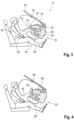
Figur 4 die schematische Schnittansicht des Insassensicherheitssystems gemäßFigur 3 im Vergleich zum Stand der Technik; -
Figuren 5-7 schematische Schnittansichten eines erfindungsgemäßen Insassensicherheitssystems gemäß einer weiteren Ausführungsform vor, während und nach seiner Aktivierung; -
Figur 8 die schematische Schnittansicht des Insassensicherheitssystems gemäßFigur 7 im Vergleich zum Stand der Technik; und -
Figur 9 eine Draufsicht auf ein Lenkrad eines erfindungsgemäßen Insassensicherheitssystems. - Die
Figuren 1 bis 3 veranschaulichen jeweils schematisch die Funktionsweise eines Insassensicherheitssystem 10 für ein Kraftfahrzeug 12 gemäß einer Ausführungsform und zeigen Momentaufnahmen vor, während und nach einer Systemaktivierung. Analog ist in denFiguren 5 bis 7 die Funktionsweise des Insassensicherheitssystems 10 gemäß einer weiteren Ausführungsform dargestellt. - Das Insassensicherheitssystem 10 umfasst ein Lenkrad 14, das zur Fahrtrichtungsänderung um eine Lenkachse A drehbar ist und einen Lenkradkranz 16 zur manuellen Betätigung des Lenkrads 14 aufweist. Der Lenkradkranz 16 ist zwischen einer Lenkbetriebsstellung und einer Insassensicherheitsstellung bewegbar, wobei der Lenkradkranz 16 eine Kranzebene E aufspannt, die sich in der Lenkbetriebsstellung senkrecht zur Lenkachse A erstreckt.
- Die Lenkbetriebsstellung gemäß den
Figuren 1 und5 erlaubt einen manuellen Lenkbetrieb, bei dem ein Fahrzeuginsasse 18 durch Verdrehen des Lenkrads 14 um die Lenkachse A eine Fahrtrichtung des Kraftfahrzeugs 12 bestimmt. - In seiner Insassensicherheitsstellung gemäß den
Figuren 3 und7 nimmt der Lenkradkranz 16 eine Position ein, die bei einer Fahrzeugkollision mit Blick auf die Insassensicherheit besonders vorteilhaft ist. Ein manueller Lenkbetrieb ist in dieser Position nicht mehr möglich. Darüber hinaus kann der Lenkradkranz 16 auch in einem automatisiertem Fahrmodus des Kraftfahrzeugs 12 in die Insassensicherheitsstellung bewegt werden, um dem Fahrzeuginsassen 18 mehr Bewegungsfreiheit zu verschaffen. Ferner befindet sich dann das Lenkrad 14 bei einer Fahrzeugkollision im automatisierten Fahrmodus bereits in einer für die Insassensicherheit vorteilhaften Position. - Der Lenkradkranz 16 ist in seiner Insassensicherheitsstellung gegenüber der Lenkbetriebsstellung entlang der Lenkachse A translatorisch verschoben und darüber hinaus so um eine Drehachse B verschwenkt, dass sich die Kranzebene E nicht mehr senkrecht zur Lenkachse A erstreckt. Das Kraftfahrzeug 12 weist zum Beispiel eine Lenkwelle 20 zur drehbaren Lagerung des Lenkrads 14 um die Lenkachse A auf, wobei die Lenkwelle 20 teleskopierbar ausgeführt ist, um eine translatorische Verschiebung des Lenkrads 14 zu ermöglichen. Gemäß
Figur 9 weist das Lenkrad 14 abgesehen vom Lenkradkranz 16 eine zentrale Lenkradnabe 22 sowie zwei Lenkradspeichen 24 auf, welche den Lenkradkranz 16 mit der Lenkradnabe 22 verbinden. - Eine Schwenkbewegung des Lenkradkranzes 16 um die Drehachse B lässt sich beispielsweise durch eine drehbare Lagerung des Lenkradkranzes 16 an der Lenkradnabe 22 oder eine drehbare Lagerung des gesamten Lenkrads 14 an der Lenkwelle 20 realisieren, wobei sich die Drehachse B im Wesentlichen horizontal durch eine 9-Uhr-Position und eine 3-Uhr-Position des Lenkradkranzes 16 (siehe
Figur 9 ) erstreckt. - Sofern sich eine Beeinträchtigung der Gassackentfaltung bereits ausschließlich durch eine translatorische Verschiebung des Lenkradkranzes 16 entlang der Lenkachse A oder ausschließlich durch eine Schwenkbewegung des Lenkradkranzes 16 um die Drehachse B zuverlässig verhindern lässt, sind selbstverständlich auch Ausführungsvarianten des Insassensicherheitssystems 10 denkbar, bei denen der Lenkradkranz 16 in seiner Insassensicherheitsstellung gegenüber der Lenkbetriebsstellung entweder translatorisch verschoben oder alternativ um die Drehachse B verschwenkt ist.
- Das Insassensicherheitssystem 10 umfasst im Übrigen einen Aktuator 26 zur Beaufschlagung des Lenkradkranzes 16 von der Lenkbetriebsstellung in die Insassensicherheitsstellung. Der Aktuator 26 ist in den dargestellten Ausführungsbeispielen ein pyrotechnischer Aktuator; alternativ wäre aber auch ein vorgespanntes Federelement oder ein elektromotorischer Antrieb denkbar. Insbesondere bei Fahrzeugen mit einem automatisierten oder autonomen Fahrmodus kann der Aktuator 26 auch als Antrieb zur reversiblen Beaufschlagung des Lenkradkranzes 16 ausgebildet sein, um den Lenkradkranz 16 für den manuellen Fahrmodus in seine Lenkbetriebsstellung sowie für den automatisierten Fahrmodus in seine Insassensicherheitsstellung zu bewegen.
- Der Aktuator 26 sorgt vorzugsweise sowohl für die translatorische Verschiebung des Lenkrads 14 entlang der Lenkachse A als auch für die Schwenkbewegung des Lenkradkranzes 16 um die Drehachse B. Darüber hinaus kann der Aktuator 26 optional auch eine Rotation um die Lenkachse A bewirken, um das Lenkrad 14 in seine Neutralstellung für Geradeausfahrt zu bewegen.
- Wie in den
Figuren 1 und5 angedeutet, weist das Insassensicherheitssystem 10 ferner eine elektrische Steuereinheit 28, einen Crash-Sensor 30 sowie wenigstens ein Gassackmodul 32, 34 auf und wird wie folgt betrieben:
Der Crash-Sensor 30 erkennt zunächst eine Kollision oder eine bevorstehende Kollision des Kraftfahrzeugs 12 und sendet ein entsprechendes Sensorsignal an die elektrische Steuereinheit 28. Daraufhin betätigt die elektrische Steuereinheit 28 den Aktuator 26 und die beiden Gassackmodule 32, 34, wobei der Aktuator 26 früher als die Gassackmodule 32, 34 oder gleichzeitig mit den Gassackmodulen 32, 34 betätigt wird. - Konkret umfasst das Insassensicherheitssystem 10 gemäß den
Figuren 1 bis 8 ein außerhalb des Lenkrads 14 verbautes Frontgassackmodul 32, wobei dieses Frontgassackmodul 32 einen Frontgassack 36 aufweist, der sich bei einer Modulaktivierung in einen Raum zwischen dem Lenkradkranz 16 und dem Fahrzeuginsassen 18 erstreckt. In den dargestellten Ausführungsbeispielen ist das Frontgassackmodul 32 hinter einer Armaturentafel 38 des Kraftfahrzeugs 12 verbaut ist, insbesondere hinter einem Abschnitt der Armaturentafel 32, welcher einer Windschutzscheibe 40 des Kraftfahrzeugs 12 zugewandt ist. Ein derartiges Frontgassackmodul 32 weist den Vorteil auf, dass es bei seiner Entfaltung die oberen Extremitäten des Fahrzeuginsassen 18 vom Lenkradkranz 16 weg nach unten beaufschlagt (sieheFiguren 3 und7 , Armrotation 33), was sich positiv auf den Rückhaltekomfort auswirkt und die Insassensicherheit bei einer Fahrzeugkollision erhöht. - Ferner umfasst das Insassensicherheitssystem 10 ein außerhalb des Lenkrads 14 verbautes Kniegassackmodul 34, wobei dieses Kniegassackmodul 34 einen Kniegassack 42 aufweist, der sich bei einer Modulaktivierung in einen Raum zwischen dem Fahrzeuginsassen 18 und der Armaturentafel 38 des Kraftfahrzeugs 12 erstreckt. In den dargestellten Ausführungsbeispielen ist das Kniegassackmodul 34 hinter der Armaturentafel 38 des Kraftfahrzeugs 12 verbaut, insbesondere hinter einem Abschnitt der Armaturentafel 38, der einem Fußraum 44 des Kraftfahrzeugs 12 zugewandt ist.
- Sowohl in der Ausführungsform gemäß den
Figuren 1 bis 3 als auch in der Ausführungsform gemäß denFiguren 5 bis 7 wird das Lenkrad 14 bei einer Aktivierung des Insassensicherheitssystems 10 translatorisch entlang der Lenkachse A verschoben, sodass es sich in der Insassensicherheitsstellung (Figuren 1 und5 ) insgesamt näher an der Armaturentafel 38 befindet als in seiner Lenkbetriebsstellung (Figuren 3 und7 ). - Wie in den
Figuren 4 und8 veranschaulicht, sind aus dem Stand der Technik bereits Insassensicherheitssysteme 10' bekannt, die bei Erfassung einer Fahrzeugkollision den Lenkradkranz 16' in der oben beschriebenen Weise translatorisch verschieben. Dabei wird jedoch deutlich, dass der herkömmliche Lenkradkranz 16' auch nach solch einer translatorischen Verlagerung zur Armaturentafel 38' hin die Entfaltung des fahrerseitigen Frontgassacks 36' und/oder des fahrerseitigen Kniegassacks 42' noch behindern oder beeinträchtigen kann. - Abgesehen von der translatorischen Verlagerung des Lenkrads 14 entlang der Lenkachse A wird der Lenkradkranz 16 daher in der Ausführungsform gemäß den
Figuren 1 bis 3 zusätzlich so um die Drehachse B verschwenkt, dass sich in der Insassensicherheitsstellung eine 12-Uhr-Position des Lenkradkranzes 16 näher an der Armaturentafel 38 und eine 6-Uhr-Position des Lenkradkranzes 16 weiter entfernt von der Armaturentafel 38 befinden als in der Lenkbetriebsstellung. Die Drehachse B verläuft dabei Sicht des Fahrzeuginsassen 18 im Wesentlichen horizontal durch eine 9-Uhr-Position und eine 3-Uhr-Position des Lenkradkranzes 16. - In der Insassensicherheitsstellung gemäß
Figur 3 befindet sich der Lenkradkranz 16 in einer besonders vorteilhaften Position zur Abstützung des Frontgassacks 36. Damit das Lenkrad 14 bei einem Insassenaufprall ein besonders stabiles Lager zur Abstützung des Frontgassacks 36 bildet, ist der Lenkradkranz 16 inFigur 9 als geschlossen umlaufender, insbesondere kreisförmiger Lenkradkranz 16 ausgebildet. - Von der Ausführungsform gemäß den
Figuren 1 bis 3 unterscheidet sich das Insassensicherheitssystem 10 gemäß denFiguren 5 bis 7 lediglich dadurch, dass der Lenkradkranz 16 hier so um die Drehachse B schwenkbar ist, dass sich in der Insassensicherheitsstellung eine 12-Uhr-Position des Lenkradkranzes 16 weiter entfernt von der Armaturentafel 38 und eine 6-Uhr-Position des Lenkradkranzes 16 näher an der Armaturentafel 38 befinden als in der Lenkbetriebsstellung. - Das Insassensicherheitssystem 10 gemäß den
Figuren 5 bis 7 weist ferner eine optionale Gassackführung 46 an der Armaturentafel 38 auf, um in der Insassensicherheitsstellung gemäßFigur 7 einen Spalt zwischen der Armaturentafel 38 und einer 12-Uhr-Position des Lenkradkranzes 16 zumindest teilweise abzudecken und den Frontgassacks 36 bei seiner Entfaltung über den Spalt hinwegzuleiten.
Claims (9)
- Insassensicherheitssystem für ein Kraftfahrzeug (12), miteinem Lenkrad (14), das zur Fahrtrichtungsänderung um eine Lenkachse (A) drehbar ist und einen Lenkradkranz (16) zur manuellen Betätigung des Lenkrads (14) aufweist,wobei der Lenkradkranz (16) zwischen einer Lenkbetriebsstellung und einer Insassensicherheitsstellung bewegbar ist,wobei der Lenkradkranz (16) eine Kranzebene (E) aufspannt, die sich in der Lenkbetriebsstellung senkrecht zur Lenkachse (A) erstreckt, undwobei der Lenkradkranz (16) in seiner Insassensicherheitsstellung gegenüber der Lenkbetriebsstellung entlang der Lenkachse (A) translatorisch verschoben ist,wobei ein außerhalb des Lenkrads (14) verbautes Kniegassackmodul (34) vorgesehen ist, welches einen Kniegassack (42) aufweist, der sich bei einer Modulaktivierung in einen Raum zwischen einer Armaturentafel (38) des Kraftfahrzeugs (12) und einem Fahrzeuginsassen (18) erstreckt,dadurch gekennzeichnet, dass der Lenkradkranz (16) in seiner Insassensicherheitsstellung gegenüber der Lenkbetriebsstellung so um eine Drehachse (B) verschwenkt ist, dass sich die Kranzebene (E) nicht mehr senkrecht zur Lenkachse (A) erstreckt,wobei ein außerhalb des Lenkrads (14) verbautes Frontgassackmodul (32) vorgesehen ist, welches einen Frontgassack (36) aufweist, der sich bei einer Modulaktivierung in einen Raum zwischen dem Lenkradkranz (16) und einem Fahrzeuginsassen (18) erstreckt.
- Insassensicherheitssystem nach Anspruch 1, dadurch gekennzeichnet, dass das Frontgassackmodul (32) hinter einer Armaturentafel (38) des Kraftfahrzeugs (12) verbaut ist, insbesondere hinter einem Abschnitt der Armaturentafel (38), welcher einer Windschutzscheibe (40) des Kraftfahrzeugs (12) zugewandt ist.
- Insassensicherheitssystem nach einem der vorhergehenden Ansprüche, dadurch gekennzeichnet, dass der Lenkradkranz (16) ein geschlossen umlaufender Lenkradkranz ist.
- Insassensicherheitssystem nach einem der vorhergehenden Ansprüche, dadurch gekennzeichnet, dass sich der Lenkradkranz (16) durch die translatorische Verschiebung entlang der Lenkachse (A) in seiner Insassensicherheitsstellung näher an einer Armaturentafel (38) befindet als in seiner Lenkbetriebsstellung.
- Insassensicherheitssystem nach einem der vorhergehenden Ansprüche, dadurch gekennzeichnet, dass sich die Drehachse (B) im Wesentlichen horizontal durch eine 9-Uhr-Position und eine 3-Uhr-Position des Lenkradkranzes (16) erstreckt, wobei der Lenkradkranz (16) so um die Drehachse (B) schwenkbar ist, dass sich in der Insassensicherheitsstellung eine 12-Uhr-Position des Lenkradkranzes (16) näher an einer Armaturentafel (38) und eine 6-Uhr-Position des Lenkradkranzes (16) weiter entfernt von der Armaturentafel (38) befinden als in der Lenkbetriebsstellung.
- Insassensicherheitssystem nach einem der Ansprüche 1 bis 4, dadurch gekennzeichnet, dass sich die Drehachse (B) im Wesentlichen horizontal durch eine 9-Uhr-Position und eine 3-Uhr-Position des Lenkradkranzes (16) erstreckt, wobei der Lenkradkranz (16) so um die Drehachse (B) schwenkbar ist, dass sich in der Insassensicherheitsstellung eine 12-Uhr-Position des Lenkradkranzes (16) weiter entfernt von einer Armaturentafel (38) und eine 6-Uhr-Position des Lenkradkranzes (16) näher an der Armaturentafel (38) befinden als in der Lenkbetriebsstellung.
- Insassensicherheitssystem nach einem der vorhergehenden Ansprüche, dadurch gekennzeichnet, dass ein Aktuator (26) zur Beaufschlagung des Lenkradkranzes (16) von der Lenkbetriebsstellung in die Insassensicherheitsstellung vorgesehen ist.
- Insassensicherheitssystem nach Anspruch 7, dadurch gekennzeichnet, dass der Aktuator (26) als Antrieb zur reversiblen Beaufschlagung des Lenkradkranzes (16) zwischen der Lenkbetriebsstellung und der Insassensicherheitsstellung ausgebildet ist.
- Verfahren zum Betreiben eines Insassensicherheitssystems (10) nach Anspruch 7 oder 8, wobei das Insassensicherheitssystem (10) eine elektrische Steuereinheit (28), einen Crash-Sensor (30) sowie wenigstens ein Gassackmodul (32, 34) umfasst, und wobei das Verfahren folgende Schritte aufweist:a) Der Crash-Sensor (30) erkennt eine Kollision oder eine bevorstehende Kollision des Kraftfahrzeugs (12) und sendet ein entsprechendes Sensorsignal an die elektrische Steuereinheit (28);b) die elektrische Steuereinheit (28) betätigt daraufhin den Aktuator (26) und das wenigstens eine Gassackmodul (32, 34), wobei der Aktuator (26) früher als das Gassackmodul (32, 34) oder gleichzeitig mit dem Gassackmodul (32, 34) betätigt wird.
Applications Claiming Priority (2)
| Application Number | Priority Date | Filing Date | Title |
|---|---|---|---|
| DE102020101803.7A DE102020101803A1 (de) | 2020-01-27 | 2020-01-27 | Insassensicherheitssystem für ein Kraftfahrzeug sowie Verfahren zum Betreiben eines solchen Insassensicherheitssystems |
| PCT/EP2021/051152 WO2021151750A1 (de) | 2020-01-27 | 2021-01-20 | Insassensicherheitssystem für ein kraftfahrzeug sowie verfahren zum betreiben eines solchen insassensicherheitssystems |
Publications (2)
| Publication Number | Publication Date |
|---|---|
| EP4096971A1 EP4096971A1 (de) | 2022-12-07 |
| EP4096971B1 true EP4096971B1 (de) | 2024-09-18 |
Family
ID=74553779
Family Applications (1)
| Application Number | Title | Priority Date | Filing Date |
|---|---|---|---|
| EP21703366.1A Active EP4096971B1 (de) | 2020-01-27 | 2021-01-20 | Insassensicherheitssystem für ein kraftfahrzeug sowie verfahren zum betreiben eines solchen insassensicherheitssystems |
Country Status (3)
| Country | Link |
|---|---|
| EP (1) | EP4096971B1 (de) |
| DE (1) | DE102020101803A1 (de) |
| WO (1) | WO2021151750A1 (de) |
Families Citing this family (8)
| Publication number | Priority date | Publication date | Assignee | Title |
|---|---|---|---|---|
| DE102022100907B3 (de) | 2022-01-17 | 2023-02-16 | Audi Aktiengesellschaft | Rückhaltevorrichtung für ein Fahrzeug |
| DE102022100908B3 (de) | 2022-01-17 | 2023-02-16 | Audi Aktiengesellschaft | Rückhaltevorrichtung für ein Fahrzeug |
| DE102022000547A1 (de) | 2022-02-14 | 2022-04-14 | Mercedes-Benz Group AG | Schutzvorrichtung für einen Kraftwagen, insbesondere für einen Personenkraftwagen, sowie Verfahren zum Betreiben einer solchen Schutzvorrichtung |
| DE102022103641B3 (de) | 2022-02-16 | 2023-06-01 | Audi Aktiengesellschaft | Rückhaltevorrichtung für ein Fahrzeug |
| DE102022000596A1 (de) | 2022-02-17 | 2022-04-07 | Mercedes-Benz Group AG | Schutzvorrichtung für einen Kraftwagen, insbesondere für einen Personenkraftwagen |
| EP4339040A1 (de) * | 2022-09-13 | 2024-03-20 | Volvo Car Corporation | Insassenschutzeinheit für ein fahrzeug und verfahren zum steuern einer insassenschutzeinheit |
| DE102022211353A1 (de) | 2022-10-26 | 2024-05-02 | Robert Bosch Gesellschaft mit beschränkter Haftung | Verfahren zum Betreiben einer Rückhaltevorrichtung von Insassen in einem Kraftfahrzeug, sowie ein Lenksäulen-Verstellsystem und ein Kraftfahrzeug zum Ausführen dieses Verfahrens |
| DE102024125082A1 (de) * | 2024-09-03 | 2026-03-05 | Zf Automotive Germany Gmbh | Frontgassack, Gassackmodul und Kraftfahrzeug mit einem solchen Frontgassack sowie Verfahren zur Entfaltung des Frontgassacks |
Family Cites Families (12)
| Publication number | Priority date | Publication date | Assignee | Title |
|---|---|---|---|---|
| JPH0725305A (ja) | 1993-07-09 | 1995-01-27 | Mazda Motor Corp | 車両用エアバッグ装置 |
| IT1286722B1 (it) | 1996-04-16 | 1998-07-17 | Fiat Auto Spa | Volante reclinabile, particolarmente per autoveicoli. |
| DE19860804A1 (de) | 1998-12-30 | 2000-07-06 | Volkswagen Ag | Anordnung eines Fahrerairbags in einem Kraftfahrzeug |
| US6581966B2 (en) | 2001-01-05 | 2003-06-24 | Ford Global Technologies, Inc. | Twin axis steering wheel system |
| JP3972765B2 (ja) * | 2002-08-08 | 2007-09-05 | タカタ株式会社 | 乗員脚部保護装置 |
| JP4477648B2 (ja) * | 2007-03-09 | 2010-06-09 | トヨタ自動車株式会社 | コラム付けニーエアバッグ装置を備えたステアリングコラム装置 |
| DE102015207477A1 (de) * | 2015-04-23 | 2016-10-27 | Bayerische Motoren Werke Aktiengesellschaft | Anordnung eines Lenkrads in einem für autonomes Fahren geeigneten Kraftfahrzeug |
| WO2018173138A1 (ja) | 2017-03-22 | 2018-09-27 | 本田技研工業株式会社 | 乗員拘束構造 |
| JPWO2018173161A1 (ja) | 2017-03-22 | 2019-11-07 | 本田技研工業株式会社 | 乗員拘束構造 |
| DE102017223111A1 (de) | 2017-12-18 | 2019-06-19 | Brose Fahrzeugteile Gmbh & Co. Kommanditgesellschaft, Coburg | Lenkvorrichtung eines Kraftfahrzeugs |
| US10864872B2 (en) * | 2018-06-14 | 2020-12-15 | GM Global Technology Operations LLC | Occupant airbag and control system for use in autonomous vehicles with retractable steering wheels |
| GB2579866B (en) | 2018-12-19 | 2021-02-24 | Ford Global Tech Llc | Movable steering wheel assemblies |
-
2020
- 2020-01-27 DE DE102020101803.7A patent/DE102020101803A1/de active Pending
-
2021
- 2021-01-20 WO PCT/EP2021/051152 patent/WO2021151750A1/de not_active Ceased
- 2021-01-20 EP EP21703366.1A patent/EP4096971B1/de active Active
Also Published As
| Publication number | Publication date |
|---|---|
| WO2021151750A1 (de) | 2021-08-05 |
| DE102020101803A1 (de) | 2021-07-29 |
| EP4096971A1 (de) | 2022-12-07 |
Similar Documents
| Publication | Publication Date | Title |
|---|---|---|
| EP4096971A1 (de) | Insassensicherheitssystem für ein kraftfahrzeug sowie verfahren zum betreiben eines solchen insassensicherheitssystems | |
| EP2698301B1 (de) | Kraftfahrzeug mit versenkbarem Lenkrad | |
| EP1420995B1 (de) | Betätigungshebel mit sollknickstelle für eine verstellbare lenksäule | |
| EP3990315B1 (de) | Fahrergassackmodul sowie lenkvorrichtung mit einem solchen fahrergassackmodul | |
| WO2014131633A1 (de) | Kraftfahrzeuglenkrad | |
| DE10124384C2 (de) | Vorrichtung zum Lenken eines Kraftfahrzeugs | |
| EP3823855B1 (de) | Kraftfahrzeug mit einer instrumententafel und verfahren zum betreiben eines kraftfahrzeugs | |
| DE102019112875A1 (de) | Lenksystem eines Fahrzeuges und Verfahren zum Betrieb eines Lenksystems eines Fahrzeuges | |
| EP3519244B1 (de) | Sitzanlage für einen kraftwagen | |
| DE102004036332B4 (de) | Kraftfahrzeug | |
| DE102015207882B4 (de) | Fahrzeuginsassen-Schutzvorrichtung, Kraftfahrzeug und Verfahren zum Betreiben einer Fahrzeuginsassen-Schutzvorrichtung | |
| EP3140161B1 (de) | Lenkradanordnung mit einem airbag, zugehöriges kraftfahrzeug und betriebsverfahren | |
| DE102010035089A1 (de) | Sicherheitseinrichtung für ein Fahrzeug, insbesondere für ein Kraftfahrzeug | |
| DE19904321A1 (de) | Insassenschutzvorrichtung eines Fahrzeugs mit einem Lenkradairbag | |
| DE102017006592A1 (de) | Fahrzeug | |
| DE102018000314B4 (de) | Lenksäule für einen Kraftwagen, insbesondere für einen Personenkraftwagen | |
| DE102022104044B4 (de) | Fahrzeugtür für einen Kraftwagen sowie Verfahren zum Betreiben einer solchen Fahrzeugtür | |
| EP0757946A2 (de) | Sicherheitseinrichtung, insbesondere für den Fahrer eines Kraftfahrzeuges | |
| DE202005005466U1 (de) | Fahrzeuginsassen-Rückhaltevorrichtung | |
| DE20009210U1 (de) | Vorrichtung zum Lenken eines Kraftfahrzeugs | |
| DE10353448B3 (de) | B-Säulenanordnung für eine Kraftfahrzeugkarosserie | |
| DE102011112992A1 (de) | Fahrzeug mit einer Gurtbringervorrichtung | |
| DE4030841A1 (de) | Lenksaeule fuer kraftfahrzeuge | |
| DE202004008985U1 (de) | Rückhaltesystem für einen Fahrzeuginsassen | |
| DE102019201622A1 (de) | Verstellbare Lenksäule für ein Kraftfahrzeug |
Legal Events
| Date | Code | Title | Description |
|---|---|---|---|
| STAA | Information on the status of an ep patent application or granted ep patent |
Free format text: STATUS: UNKNOWN |
|
| STAA | Information on the status of an ep patent application or granted ep patent |
Free format text: STATUS: THE INTERNATIONAL PUBLICATION HAS BEEN MADE |
|
| PUAI | Public reference made under article 153(3) epc to a published international application that has entered the european phase |
Free format text: ORIGINAL CODE: 0009012 |
|
| STAA | Information on the status of an ep patent application or granted ep patent |
Free format text: STATUS: REQUEST FOR EXAMINATION WAS MADE |
|
| 17P | Request for examination filed |
Effective date: 20220829 |
|
| AK | Designated contracting states |
Kind code of ref document: A1 Designated state(s): AL AT BE BG CH CY CZ DE DK EE ES FI FR GB GR HR HU IE IS IT LI LT LU LV MC MK MT NL NO PL PT RO RS SE SI SK SM TR |
|
| DAV | Request for validation of the european patent (deleted) | ||
| DAX | Request for extension of the european patent (deleted) | ||
| GRAP | Despatch of communication of intention to grant a patent |
Free format text: ORIGINAL CODE: EPIDOSNIGR1 |
|
| STAA | Information on the status of an ep patent application or granted ep patent |
Free format text: STATUS: GRANT OF PATENT IS INTENDED |
|
| INTG | Intention to grant announced |
Effective date: 20240424 |
|
| GRAS | Grant fee paid |
Free format text: ORIGINAL CODE: EPIDOSNIGR3 |
|
| GRAA | (expected) grant |
Free format text: ORIGINAL CODE: 0009210 |
|
| STAA | Information on the status of an ep patent application or granted ep patent |
Free format text: STATUS: THE PATENT HAS BEEN GRANTED |
|
| AK | Designated contracting states |
Kind code of ref document: B1 Designated state(s): AL AT BE BG CH CY CZ DE DK EE ES FI FR GB GR HR HU IE IS IT LI LT LU LV MC MK MT NL NO PL PT RO RS SE SI SK SM TR |
|
| REG | Reference to a national code |
Ref country code: GB Ref legal event code: FG4D Free format text: NOT ENGLISH |
|
| REG | Reference to a national code |
Ref country code: CH Ref legal event code: EP |
|
| REG | Reference to a national code |
Ref country code: IE Ref legal event code: FG4D Free format text: LANGUAGE OF EP DOCUMENT: GERMAN |
|
| REG | Reference to a national code |
Ref country code: DE Ref legal event code: R096 Ref document number: 502021005179 Country of ref document: DE |
|
| REG | Reference to a national code |
Ref country code: LT Ref legal event code: MG9D |
|
| PG25 | Lapsed in a contracting state [announced via postgrant information from national office to epo] |
Ref country code: NO Free format text: LAPSE BECAUSE OF FAILURE TO SUBMIT A TRANSLATION OF THE DESCRIPTION OR TO PAY THE FEE WITHIN THE PRESCRIBED TIME-LIMIT Effective date: 20241218 |
|
| PG25 | Lapsed in a contracting state [announced via postgrant information from national office to epo] |
Ref country code: GR Free format text: LAPSE BECAUSE OF FAILURE TO SUBMIT A TRANSLATION OF THE DESCRIPTION OR TO PAY THE FEE WITHIN THE PRESCRIBED TIME-LIMIT Effective date: 20241219 Ref country code: FI Free format text: LAPSE BECAUSE OF FAILURE TO SUBMIT A TRANSLATION OF THE DESCRIPTION OR TO PAY THE FEE WITHIN THE PRESCRIBED TIME-LIMIT Effective date: 20240918 |
|
| PG25 | Lapsed in a contracting state [announced via postgrant information from national office to epo] |
Ref country code: BG Free format text: LAPSE BECAUSE OF FAILURE TO SUBMIT A TRANSLATION OF THE DESCRIPTION OR TO PAY THE FEE WITHIN THE PRESCRIBED TIME-LIMIT Effective date: 20240918 |
|
| PG25 | Lapsed in a contracting state [announced via postgrant information from national office to epo] |
Ref country code: LV Free format text: LAPSE BECAUSE OF FAILURE TO SUBMIT A TRANSLATION OF THE DESCRIPTION OR TO PAY THE FEE WITHIN THE PRESCRIBED TIME-LIMIT Effective date: 20240918 |
|
| PG25 | Lapsed in a contracting state [announced via postgrant information from national office to epo] |
Ref country code: HR Free format text: LAPSE BECAUSE OF FAILURE TO SUBMIT A TRANSLATION OF THE DESCRIPTION OR TO PAY THE FEE WITHIN THE PRESCRIBED TIME-LIMIT Effective date: 20240918 |
|
| REG | Reference to a national code |
Ref country code: NL Ref legal event code: MP Effective date: 20240918 |
|
| PG25 | Lapsed in a contracting state [announced via postgrant information from national office to epo] |
Ref country code: RS Free format text: LAPSE BECAUSE OF FAILURE TO SUBMIT A TRANSLATION OF THE DESCRIPTION OR TO PAY THE FEE WITHIN THE PRESCRIBED TIME-LIMIT Effective date: 20241218 |
|
| PG25 | Lapsed in a contracting state [announced via postgrant information from national office to epo] |
Ref country code: RS Free format text: LAPSE BECAUSE OF FAILURE TO SUBMIT A TRANSLATION OF THE DESCRIPTION OR TO PAY THE FEE WITHIN THE PRESCRIBED TIME-LIMIT Effective date: 20241218 Ref country code: NO Free format text: LAPSE BECAUSE OF FAILURE TO SUBMIT A TRANSLATION OF THE DESCRIPTION OR TO PAY THE FEE WITHIN THE PRESCRIBED TIME-LIMIT Effective date: 20241218 Ref country code: LV Free format text: LAPSE BECAUSE OF FAILURE TO SUBMIT A TRANSLATION OF THE DESCRIPTION OR TO PAY THE FEE WITHIN THE PRESCRIBED TIME-LIMIT Effective date: 20240918 Ref country code: HR Free format text: LAPSE BECAUSE OF FAILURE TO SUBMIT A TRANSLATION OF THE DESCRIPTION OR TO PAY THE FEE WITHIN THE PRESCRIBED TIME-LIMIT Effective date: 20240918 Ref country code: GR Free format text: LAPSE BECAUSE OF FAILURE TO SUBMIT A TRANSLATION OF THE DESCRIPTION OR TO PAY THE FEE WITHIN THE PRESCRIBED TIME-LIMIT Effective date: 20241219 Ref country code: FI Free format text: LAPSE BECAUSE OF FAILURE TO SUBMIT A TRANSLATION OF THE DESCRIPTION OR TO PAY THE FEE WITHIN THE PRESCRIBED TIME-LIMIT Effective date: 20240918 Ref country code: BG Free format text: LAPSE BECAUSE OF FAILURE TO SUBMIT A TRANSLATION OF THE DESCRIPTION OR TO PAY THE FEE WITHIN THE PRESCRIBED TIME-LIMIT Effective date: 20240918 |
|
| PG25 | Lapsed in a contracting state [announced via postgrant information from national office to epo] |
Ref country code: NL Free format text: LAPSE BECAUSE OF FAILURE TO SUBMIT A TRANSLATION OF THE DESCRIPTION OR TO PAY THE FEE WITHIN THE PRESCRIBED TIME-LIMIT Effective date: 20240918 |
|
| PG25 | Lapsed in a contracting state [announced via postgrant information from national office to epo] |
Ref country code: IS Free format text: LAPSE BECAUSE OF FAILURE TO SUBMIT A TRANSLATION OF THE DESCRIPTION OR TO PAY THE FEE WITHIN THE PRESCRIBED TIME-LIMIT Effective date: 20250118 Ref country code: PT Free format text: LAPSE BECAUSE OF FAILURE TO SUBMIT A TRANSLATION OF THE DESCRIPTION OR TO PAY THE FEE WITHIN THE PRESCRIBED TIME-LIMIT Effective date: 20250120 |
|
| PG25 | Lapsed in a contracting state [announced via postgrant information from national office to epo] |
Ref country code: SM Free format text: LAPSE BECAUSE OF FAILURE TO SUBMIT A TRANSLATION OF THE DESCRIPTION OR TO PAY THE FEE WITHIN THE PRESCRIBED TIME-LIMIT Effective date: 20240918 Ref country code: RO Free format text: LAPSE BECAUSE OF FAILURE TO SUBMIT A TRANSLATION OF THE DESCRIPTION OR TO PAY THE FEE WITHIN THE PRESCRIBED TIME-LIMIT Effective date: 20240918 |
|
| PG25 | Lapsed in a contracting state [announced via postgrant information from national office to epo] |
Ref country code: ES Free format text: LAPSE BECAUSE OF FAILURE TO SUBMIT A TRANSLATION OF THE DESCRIPTION OR TO PAY THE FEE WITHIN THE PRESCRIBED TIME-LIMIT Effective date: 20240918 |
|
| PG25 | Lapsed in a contracting state [announced via postgrant information from national office to epo] |
Ref country code: EE Free format text: LAPSE BECAUSE OF FAILURE TO SUBMIT A TRANSLATION OF THE DESCRIPTION OR TO PAY THE FEE WITHIN THE PRESCRIBED TIME-LIMIT Effective date: 20240918 |
|
| PGFP | Annual fee paid to national office [announced via postgrant information from national office to epo] |
Ref country code: AT Payment date: 20250417 Year of fee payment: 5 |
|
| PG25 | Lapsed in a contracting state [announced via postgrant information from national office to epo] |
Ref country code: PL Free format text: LAPSE BECAUSE OF FAILURE TO SUBMIT A TRANSLATION OF THE DESCRIPTION OR TO PAY THE FEE WITHIN THE PRESCRIBED TIME-LIMIT Effective date: 20240918 Ref country code: CZ Free format text: LAPSE BECAUSE OF FAILURE TO SUBMIT A TRANSLATION OF THE DESCRIPTION OR TO PAY THE FEE WITHIN THE PRESCRIBED TIME-LIMIT Effective date: 20240918 |
|
| PG25 | Lapsed in a contracting state [announced via postgrant information from national office to epo] |
Ref country code: SK Free format text: LAPSE BECAUSE OF FAILURE TO SUBMIT A TRANSLATION OF THE DESCRIPTION OR TO PAY THE FEE WITHIN THE PRESCRIBED TIME-LIMIT Effective date: 20240918 Ref country code: IT Free format text: LAPSE BECAUSE OF FAILURE TO SUBMIT A TRANSLATION OF THE DESCRIPTION OR TO PAY THE FEE WITHIN THE PRESCRIBED TIME-LIMIT Effective date: 20240918 |
|
| REG | Reference to a national code |
Ref country code: DE Ref legal event code: R097 Ref document number: 502021005179 Country of ref document: DE |
|
| PG25 | Lapsed in a contracting state [announced via postgrant information from national office to epo] |
Ref country code: DK Free format text: LAPSE BECAUSE OF FAILURE TO SUBMIT A TRANSLATION OF THE DESCRIPTION OR TO PAY THE FEE WITHIN THE PRESCRIBED TIME-LIMIT Effective date: 20240918 |
|
| PLBE | No opposition filed within time limit |
Free format text: ORIGINAL CODE: 0009261 |
|
| STAA | Information on the status of an ep patent application or granted ep patent |
Free format text: STATUS: NO OPPOSITION FILED WITHIN TIME LIMIT |
|
| 26N | No opposition filed |
Effective date: 20250619 |
|
| REG | Reference to a national code |
Ref country code: CH Ref legal event code: PL |
|
| PG25 | Lapsed in a contracting state [announced via postgrant information from national office to epo] |
Ref country code: SE Free format text: LAPSE BECAUSE OF FAILURE TO SUBMIT A TRANSLATION OF THE DESCRIPTION OR TO PAY THE FEE WITHIN THE PRESCRIBED TIME-LIMIT Effective date: 20240918 |
|
| PG25 | Lapsed in a contracting state [announced via postgrant information from national office to epo] |
Ref country code: LU Free format text: LAPSE BECAUSE OF NON-PAYMENT OF DUE FEES Effective date: 20250120 Ref country code: MC Free format text: LAPSE BECAUSE OF FAILURE TO SUBMIT A TRANSLATION OF THE DESCRIPTION OR TO PAY THE FEE WITHIN THE PRESCRIBED TIME-LIMIT Effective date: 20240918 |
|
| GBPC | Gb: european patent ceased through non-payment of renewal fee |
Effective date: 20250120 |
|
| PG25 | Lapsed in a contracting state [announced via postgrant information from national office to epo] |
Ref country code: BE Free format text: LAPSE BECAUSE OF NON-PAYMENT OF DUE FEES Effective date: 20250131 Ref country code: GB Free format text: LAPSE BECAUSE OF NON-PAYMENT OF DUE FEES Effective date: 20250120 |
|
| PG25 | Lapsed in a contracting state [announced via postgrant information from national office to epo] |
Ref country code: CH Free format text: LAPSE BECAUSE OF NON-PAYMENT OF DUE FEES Effective date: 20250131 |
|
| REG | Reference to a national code |
Ref country code: BE Ref legal event code: MM Effective date: 20250131 |
|
| PGFP | Annual fee paid to national office [announced via postgrant information from national office to epo] |
Ref country code: FR Payment date: 20251208 Year of fee payment: 6 |
|
| PG25 | Lapsed in a contracting state [announced via postgrant information from national office to epo] |
Ref country code: IE Free format text: LAPSE BECAUSE OF NON-PAYMENT OF DUE FEES Effective date: 20250120 |
|
| PGFP | Annual fee paid to national office [announced via postgrant information from national office to epo] |
Ref country code: DE Payment date: 20260131 Year of fee payment: 6 |