EP4096885B1 - Modular element for suction cutting bed in an automatic machine for cutting sheet material - Google Patents
Modular element for suction cutting bed in an automatic machine for cutting sheet material Download PDFInfo
- Publication number
- EP4096885B1 EP4096885B1 EP21716799.8A EP21716799A EP4096885B1 EP 4096885 B1 EP4096885 B1 EP 4096885B1 EP 21716799 A EP21716799 A EP 21716799A EP 4096885 B1 EP4096885 B1 EP 4096885B1
- Authority
- EP
- European Patent Office
- Prior art keywords
- bristles
- modular element
- modular
- support
- head
- Prior art date
- Legal status (The legal status is an assumption and is not a legal conclusion. Google has not performed a legal analysis and makes no representation as to the accuracy of the status listed.)
- Active
Links
- 238000005520 cutting process Methods 0.000 title claims description 61
- 239000000463 material Substances 0.000 title claims description 21
- 238000000465 moulding Methods 0.000 claims description 5
- 210000004209 hair Anatomy 0.000 description 32
- 238000004519 manufacturing process Methods 0.000 description 7
- 239000004575 stone Substances 0.000 description 4
- 230000000149 penetrating effect Effects 0.000 description 3
- 210000004919 hair shaft Anatomy 0.000 description 2
- 239000004753 textile Substances 0.000 description 2
- 241000549893 Carphochaete Species 0.000 description 1
- 235000010627 Phaseolus vulgaris Nutrition 0.000 description 1
- 244000046052 Phaseolus vulgaris Species 0.000 description 1
- 239000000654 additive Substances 0.000 description 1
- 230000000996 additive effect Effects 0.000 description 1
- 239000004744 fabric Substances 0.000 description 1
- 239000003292 glue Substances 0.000 description 1
- 230000003993 interaction Effects 0.000 description 1
- 238000000034 method Methods 0.000 description 1
Images


Classifications
-
- B—PERFORMING OPERATIONS; TRANSPORTING
- B26—HAND CUTTING TOOLS; CUTTING; SEVERING
- B26D—CUTTING; DETAILS COMMON TO MACHINES FOR PERFORATING, PUNCHING, CUTTING-OUT, STAMPING-OUT OR SEVERING
- B26D7/00—Details of apparatus for cutting, cutting-out, stamping-out, punching, perforating, or severing by means other than cutting
- B26D7/01—Means for holding or positioning work
- B26D7/018—Holding the work by suction
-
- B—PERFORMING OPERATIONS; TRANSPORTING
- B26—HAND CUTTING TOOLS; CUTTING; SEVERING
- B26D—CUTTING; DETAILS COMMON TO MACHINES FOR PERFORATING, PUNCHING, CUTTING-OUT, STAMPING-OUT OR SEVERING
- B26D7/00—Details of apparatus for cutting, cutting-out, stamping-out, punching, perforating, or severing by means other than cutting
- B26D7/06—Arrangements for feeding or delivering work of other than sheet, web, or filamentary form
- B26D7/0625—Arrangements for feeding or delivering work of other than sheet, web, or filamentary form by endless conveyors, e.g. belts
-
- B—PERFORMING OPERATIONS; TRANSPORTING
- B26—HAND CUTTING TOOLS; CUTTING; SEVERING
- B26D—CUTTING; DETAILS COMMON TO MACHINES FOR PERFORATING, PUNCHING, CUTTING-OUT, STAMPING-OUT OR SEVERING
- B26D7/00—Details of apparatus for cutting, cutting-out, stamping-out, punching, perforating, or severing by means other than cutting
- B26D7/20—Cutting beds
Definitions
- the present invention relates to a suction cutting support for an automatic cutting machine for sheet materials, in particular textile materials, using a vibrating blade penetrating into the cutting support. It concerns more precisely a modular element intended to form such a cutting support.
- One field of application of the invention is that of the automatic cutting of stacks or mats of sheets of materials, in particular textile materials, using a vibrating blade penetrating into a suction cutting support.
- a vibrating blade cutting machine typically includes a cutting conveyor which serves to drive the stack of sheets during the cutting operation.
- This cutting conveyor is housed in a box inside which a strong depression is established in order to keep the sheets of material to be cut stationary during the cutting operation.
- the cutting conveyor also serves as a penetrating cutting support for the vibrating blade. It is in fact well known to make the cutting support penetrable by the blade so that during the cutting operation, the blade can not only completely pass through the material to be cut, but also extend downward beyond the support surface and in the bed of material providing such a surface.
- the cutting support is generally made up of an assembly of blocks driven by a belt. More precisely, each block comprises a plurality of bristles mounted on a sole in several parallel rows, each bristle having a head forming the support for the sheet material to be cut. Transverse channels are made through the sole to allow the passage of suction air. These blocks thus make it possible to support the material to be cut under suction while being able to be penetrated by the cutting blade.
- Cutting support blocks are most often obtained by molding plastic material. Molding makes it possible to obtain a paving stone in one piece with the sole and all of its bristles. To ensure the unmolding of such a part, it is necessary that the bristles, which generally have a conical or cylindrical shape, have a head diameter smaller than the base diameter. We can in particular refer to the document US 4,205,835 which describes an exemplary embodiment of such a cutting support block.
- the tip of the cutting blades being beveled, the interference between the blade and the hairs is favored by the conicity of the hairs associated with their flexibility, which can result in partial or total cuts of hairs.
- the height position of this cut is directly linked to the conicity of the hairs and the blade or the position of the blade in relation to the generator of the hairs encountered by the blade.
- the need to have bristles whose foot has a larger diameter than the head has the disadvantage of limiting the space on the sole to make the passage channels for the suction air, which reduces as much as the suction capacity of the cutting support.
- a modular suction cutting support element of an automatic blade cutting machine for sheet materials comprising a plurality of bristles arranged in the same and single line, at least certain bristles each having a foot secured to a sole intended to be mounted on a support, an end opposite the foot on which is intended to rest a sheet material to be cut, and a rod connecting the head to the foot, the sole comprising, at each of its lateral faces, a plurality transverse channels for the passage of suction air communicating an upper face of the sole from which the bristles extend with an inner face opposite the upper face.
- the invention therefore aims to propose a cutting support which does not present the aforementioned drawbacks.
- a modular suction cutting support element of an automatic blade cutting machine for sheet materials comprising a plurality of bristles arranged along the same and single line, at least certain hairs each having a foot attached to a sole intended to be mounted on a support, a head opposite the foot on which is intended to rest a sheet material to be cut, and a rod connecting the head to the foot and the largest straight section of which is strictly included in the largest straight section of the head, the sole comprising, at each of its lateral faces, a plurality of transverse channels for the passage of suction air causing an upper face of the sole from which the bristles extend to communicate with an inner face opposite the upper face.
- straight section here we mean a section made perpendicular to the axis of the hair.
- strictly included we mean here that all the points of the largest straight section of the shaft of each hair are included (or encompassed) in the largest straight section of the head of the hair but that at least a point of the largest cross section of the head is not included in the largest cross section of the rod.
- this condition is equivalent to the cross section of the head having a diameter strictly greater than that of the shaft.
- the invention is remarkable in that it makes it possible to produce cutting supports by mounting a plurality of modular elements on at least one support.
- each modular element comprises bristles arranged along the same and single line, it is possible to give at least certain bristles a head having a straight section encompassing a straight section of the rod, while retaining the ability to manufacture these modular elements by molded in one piece with their sole and their hairs.
- Such a geometric shape of the bristles has the advantage of limiting interactions between the tip of the cutting blade and the tangent bristles.
- the support surface offered by these modular elements is better due to the fact that the head of the bristles has a larger cross section than that of the rods.
- the cross section of the rods and feet of the bristles it is easier to increase the diameter of the transverse channels for the passage of suction air, and thus to improve the air porosity of the sole in order to maintain maximum suction and limit pressure losses.
- Another advantage linked to the production of cutting supports by mounting a plurality of modular elements according to the invention lies in the possibility of being able to offer cutting supports differentiated by cutting blade, professions, etc.
- the sole further comprises, at each of its lateral faces, at least one longitudinal channel extending between the ends longitudinal of the sole and communicating with the transverse channels in order to distribute the suction air evenly in the transverse channels.
- This characteristic makes it possible to make the suction of the modular element more homogeneous over the entire surface of the sole.
- the sole further comprises, at each of its lateral faces, at least one mechanical assembly member with another modular element.
- each mechanical assembly member may comprise at least one lug projecting relative to a side face of the sole and intended to fit into a corresponding recess of an assembly member of a modular element adjacent, and a recess set back from the side face of the sole and intended to receive by nesting a corresponding lug of the assembly member of the adjacent modular element.
- At least some hairs may include a head having a truncated cone shape and a shaft having a cylindrical shape.
- the head of these hairs may have the shape of a truncated cone having a circular cross section on the inner side which is greater than that on the outer side.
- the head of these hairs may have the shape of an inverted truncated cone having a circular cross section on the exterior side which is greater than that on the interior side.
- At least certain hairs may have a rod and a head having a straight section of polygonal shape, for example a rod of straight section of hexagonal shape and a head of straight section of octagonal shape.
- the sole may further comprise a fastener at each longitudinal end for assembling the modular element on a support, and two fingers projecting inwards and acting as centralizers on the support.
- the transverse channels can have a cross section of semi-circular shape so as to form transverse passages of cylindrical shape when another modular element is mounted against said element.
- the bristles of the same modular element can be arranged in a straight line forming a single row of bristles.
- the bristles can be arranged in a broken line forming two parallel rows of bristles.
- the modular element may comprise at least two bristles whose respective heads have different shapes.
- the invention also relates to a suction cutting support for an automatic cutting machine for sheet materials comprising a plurality of modular elements as defined above and mounted on at least one support.
- the modular elements can be mounted on the support so as to obtain an orderly alignment of the bristles.
- modular elements can be mounted on the support so as to obtain a staggered alignment of the bristles.
- certain modular elements are mounted on the support so as to obtain an orderly alignment of the bristles and certain other modular elements are mounted on the same support so as to obtain a staggered alignment of the bristles.
- the distance between two adjacent hairs is greater than the largest dimension of the cross section of the hair shaft. This characteristic prevents a cut hair coming from the bottom of the paving stone from separating the surrounding hairs.
- the conveyor of a vibrating blade cutting machine allows the material to be cut to be carried during the cutting operation.
- the upper part of the conveyor serves as a cutting support and the lower part is generally housed in a box inside which a strong depression is established in order to keep the material to be cut stationary during the cutting operation.
- the actual cutting support may typically consist of an assembly of a plurality of blocks mounted on a drive belt such as the cutting support block 2 shown on the figure 1 .
- This cutting support block 2 consists of the assembly between them of a plurality of modular elements 4 (for example eleven in number in the embodiment represented by the figure 1 ).
- the modular elements are assembled together by interlocking their respective side faces as described below.
- each modular element 4 comprises a plurality of bristles 6 which are aligned in the same and single row of bristles.
- These bristles 6 each have a foot 8 which is secured to a sole 10 common to all of the bristles, a head 12 which is opposite the foot and which is intended to serve as a cutting support, and a rod 9 which connects the foot to head.
- each hair 6 has the particularity of having a head 12 whose largest straight section (that is to say the largest section made perpendicular to the main axis of the hair) encompasses the largest straight section of its stem 9.
- the largest cross section of the head is strictly larger than the largest cross section of stem 9 (i.e. it surrounds it while being larger).
- the largest straight section of the head has a diameter D which is strictly greater than the largest diameter d of the straight section of the rod.
- the head 12 of each hair has the shape of an inverted truncated cone having a circular cross section on the outer side which is greater than that on the inner side (i.e. the large base B of the truncated cone is arranged towards the outside of the modular element and the small base b of the truncated cone is turned towards the inside).
- the invention is not limited to these particular geometric shapes for the hair, its head and its foot.
- the foot has the shape of a truncated cone or pyramid with a polygonal base and the head has a straight section other than circular (square, hexagonal, etc.).
- the sole 10 of each of them can comprise, at each of its two lateral faces 10a, 10b, at least one mechanical assembly member 13 with another modular element.
- each of the lateral faces 10a, 10b of the sole of a modular element can be provided with four mechanical assembly members spaced from each other, namely: an end assembly member 13a at each of its longitudinal ends 10c, 10d and two central assembly members 13b positioned between its longitudinal ends.
- the assembly members 13 of the two side faces of a modular element can be aligned opposite each other.
- the mechanical assembly members 13 can each comprise at least one lug 14 which projects relative to the side face of the sole and a recess 16 set back relative to the side face of the sole, the lug and the recess being for example positioned transversely one above the other.
- the lugs 14 of the mechanical assembly members of one of the modular elements fit inside the recesses 16 of the mechanical assembly members of the other modular element (and vice versa) with support that can be ensured by glue or by clipping for example.
- the assembly of several modular elements together ensures continuity of the upper face of the sole.
- the modular elements could simply be positioned next to each other on a paving stone or directly on a support and held together by a suitable mechanism.
- the two lateral faces 10a, 10b of the sole 10 of the modular element each comprise a plurality of transverse channels 18 which communicate the exterior face of the sole (that is to say the face to from which the hairs extend) with its interior face (that is to say the face opposite to the exterior face).
- transverse channels 18 which are advantageously regularly distributed over the entire length of the sole make it possible to give porosity to the sole by allowing the suction air to pass through the sole.
- the transverse channels 18 can each have a cross section of semi-circular shape so as to form transverse passages of cylindrical shape when two modular elements are mounted against each other.
- the sole 10 of the modular element further comprises, at each of its two lateral faces 10a, 10b, a longitudinal channel 20 which extends between its two longitudinal ends 10c, 10d and which communicates with the transverse channels 18 in order to distribute the suction air evenly in the latter.
- the longitudinal channel 20 may have a cross section of semi-circular shape so as to form a longitudinal passage of cylindrical shape when two modular elements are mounted against each other.
- the sole 10 of the modular element further comprises at least one hook-shaped fastener 22 at each of its longitudinal ends 10c, 10d, and two fingers 24 projecting towards the inside of the sole.
- the hook-shaped fasteners 22 make it possible to mount the cutting support block formed by the assembly of several modular elements on a support (not shown) intended to be mounted directly on the drive belt of the cutting conveyor. As for the fingers 24, they play the role of centerers on the support.
- the modular elements are assembled within the same block so as to obtain an ordered alignment of the blocks bristles, that is to say that the bristles 6 within the same block 2 are aligned in the longitudinal and transverse directions.
- At least some of the modular elements of the same block can be assembled so as to obtain a staggered alignment of the bristles.
- the modular elements 4-1 to 4-4 are assembled so as to obtain an ordered alignment of the bristles, while the modular elements 4'-1 to 4'-4 are assembled so as to obtain a staggered alignment of the bristles.
- the modular elements 4'-1 to 4'-4 are assembled so as to obtain a staggered alignment of the bristles.
- other configurations are possible depending on needs by mixing the two types of modular elements.
- FIG. 7 represents in detail and in perspective a modular element 4' making it possible to obtain a staggered assembly of the bristles within the same support block.
- this modular element 4' is distinguished by the shape of the transverse channels 18' for the passage of suction air between the interior face and the exterior face of the sole 10.
- the transverse channels 18' of the modular element 4' each have a straight section in the shape of a double semi-circle so as to form transverse passages 26 in the shape of a bean when another element modular is assembled on said element (see the Figure 6 ).
- a longitudinal channel 20' extending between the longitudinal ends of the sole communicates with the transverse channels 18' in order to distribute the suction air evenly in the latter.
- FIG 8 represents a hair head of a modular element according to a variant embodiment, this hair shape being able to be applied equally well to the modular elements of the embodiment of the figures 1 to 4 than those of the mode of realization of the figures 5 to 7 .
- the head 12' of the bristles 6' has the shape of a truncated cone having a circular cross section on the inner side which is greater than that on the outer side (ie the small base b ' of the truncated cone is arranged towards the exterior of the modular element and the large base B 'of the truncated cone is turned inwards).
- the head 12' also has a circular cross section, the largest cross section of which (that is to say at the level of the large base B ') has a diameter D' which is strictly greater than the largest large diameter of the circular straight section of the hair shaft 9'.
- the rod 9, 9' of each bristle 6, 6' can have a cylindrical shape between its head 12, 12' and its foot 8, 8'.
- any other shape is also possible (for example with a square, polygonal cross section, etc.).
- Figure 9 represents yet another alternative embodiment of a modular cutting support element 4" in which the rod 9" of the bristles 6" has a straight section of hexagonal shape between the head 12" and the foot 8". Furthermore, in this alternative embodiment, the 12" head has a straight section of octagonal shape.
- Such a general shape of the bristles 6, 6', 6" and the production of modular elements comprising single rows of bristles makes it possible to manufacture the latter by molding in a single piece.
- such a configuration makes it possible to overcome the hair shape constraints required for demoulding.
- all the hairs of the same modular element do not necessarily have a head whose cross section includes the largest cross section of the rod. It is in fact possible to envisage that only certain bristles of the same modular element have such a characteristic, the other bristles of the modular element having a head of straight section identical to that of their stem.
- FIGS 10A And 10B show two possible arrangements for the bristles 6, 6', 6" of the same modular element 4, 4'.
- the bristles of the same modular element are arranged along a straight line L1 forming a single row of bristles.
- the respective longitudinal axes of the hairs are all aligned on the same straight line L1.
- the bristles of the same modular element can be arranged along a broken (or sawtooth) line L2 so as to form two rows of bristles R1, R2 which are parallel.
- the modular element can be manufactured by molding in a single piece.
- the modular element 4 according to the invention can be devoid of mechanical assembly member.
- the modular elements of the same support are simply positioned against each other on the same support and held together by an appropriate mechanism.
- FIG. 12 illustrates, partially, yet another alternative embodiment of a modular cutting support element 4"' in which the heads of the bristles have different shapes.
- the modular element comprises an alternation of bristles 6a whose respective head 12a has a truncated cone shape whose large base faces outwards and bristles 6b whose respective head 12b has a truncated cone shape whose the large base faces inwards.
- Such a “head-to-tail” alternation of the hair heads has the advantage of increasing the apparent density of the hairs, which makes it possible to increase the hold of the fabric.
Description
La présente invention est relative à un support de coupe à aspiration pour machine de coupe automatique de matériaux en feuilles, notamment de matériaux textiles, à l'aide d'une lame vibrante pénétrant dans le support de coupe. Elle concerne plus précisément un élément modulaire destiné à former un tel support de coupe.The present invention relates to a suction cutting support for an automatic cutting machine for sheet materials, in particular textile materials, using a vibrating blade penetrating into the cutting support. It concerns more precisely a modular element intended to form such a cutting support.
Un domaine d'application de l'invention est celui de la découpe automatique de piles ou de matelas de feuilles de matériaux, notamment de matériaux textiles, à l'aide d'une lame vibrante pénétrant dans un support de coupe à aspiration.One field of application of the invention is that of the automatic cutting of stacks or mats of sheets of materials, in particular textile materials, using a vibrating blade penetrating into a suction cutting support.
Typiquement, une machine de coupe à lame vibrante comprend notamment un convoyeur de coupe qui sert à entraîner la pile de feuilles durant l'opération de coupe. Ce convoyeur de coupe est logé dans un caisson à l'intérieur duquel est établie une forte dépression afin de maintenir immobiles les feuilles de matériau à découper durant l'opération de coupe.Typically, a vibrating blade cutting machine includes a cutting conveyor which serves to drive the stack of sheets during the cutting operation. This cutting conveyor is housed in a box inside which a strong depression is established in order to keep the sheets of material to be cut stationary during the cutting operation.
Dans ce type de machine, le convoyeur de coupe sert également de support de coupe pénétrant pour la lame vibrante. Il est en effet bien connu de rendre le support de coupe pénétrable par la lame de sorte que durant l'opération de coupe, la lame puisse non seulement traverser complètement le matériau à couper, mais également s'étendre vers le bas au-delà de la surface de support et dans le lit de matériau fournissant une telle surface.In this type of machine, the cutting conveyor also serves as a penetrating cutting support for the vibrating blade. It is in fact well known to make the cutting support penetrable by the blade so that during the cutting operation, the blade can not only completely pass through the material to be cut, but also extend downward beyond the support surface and in the bed of material providing such a surface.
Pour ce faire, le support de coupe est généralement constitué d'un assemblage de pavés entraînés par une courroie. Plus précisément, chaque pavé comprend une pluralité de poils montés sur une semelle en plusieurs rangées parallèles, chaque poil ayant une tête formant le support pour le matériau en feuilles à découper. Des canaux transversaux sont pratiqués au travers de la semelle pour permettre le passage de l'air d'aspiration. Ces pavés permettent ainsi de supporter le matériau à découper sous aspiration tout en pouvant être pénétrés par la lame de coupe.To do this, the cutting support is generally made up of an assembly of blocks driven by a belt. More precisely, each block comprises a plurality of bristles mounted on a sole in several parallel rows, each bristle having a head forming the support for the sheet material to be cut. Transverse channels are made through the sole to allow the passage of suction air. These blocks thus make it possible to support the material to be cut under suction while being able to be penetrated by the cutting blade.
Les pavés de support de coupe sont le plus souvent obtenus par moulage de matière plastique. Le moulage permet d'obtenir un pavé en une seule pièce avec la semelle et l'ensemble des poils de celui-ci. Pour assurer le démoulage d'une telle pièce, il est nécessaire que les poils, qui ont généralement une forme conique ou cylindrique, présentent un diamètre en tête plus petit que le diamètre en pied. On pourra notamment se référer au document
Or, la pointe des lames de coupe étant biseautée, l'interférence entre la lame et les poils est favorisée par la conicité des poils associée à leur flexibilité, ce qui peut entraîner des coupes partielles ou totales de poils. La position en hauteur de cette découpe est directement liée à la conicité des poils et de la lame ou de la position de la lame par rapport à la génératrice des poils rencontrés par la lame.However, the tip of the cutting blades being beveled, the interference between the blade and the hairs is favored by the conicity of the hairs associated with their flexibility, which can result in partial or total cuts of hairs. The height position of this cut is directly linked to the conicity of the hairs and the blade or the position of the blade in relation to the generator of the hairs encountered by the blade.
Par ailleurs, la nécessité d'avoir des poils dont le pied présente un diamètre plus grand que la tête a pour inconvénient de limiter l'espace sur la semelle pour pratiquer les canaux de passage de l'air d'aspiration, ce qui réduit d'autant la capacité d'aspiration du support de coupe.Furthermore, the need to have bristles whose foot has a larger diameter than the head has the disadvantage of limiting the space on the sole to make the passage channels for the suction air, which reduces as much as the suction capacity of the cutting support.
Le document
Exposé de l'invention L'invention a donc pour but de proposer un support de coupe qui ne présente pas les inconvénients précités.Presentation of the invention The invention therefore aims to propose a cutting support which does not present the aforementioned drawbacks.
Conformément à l'invention, ce but est atteint grâce à un élément modulaire de support de coupe à aspiration d'une machine de coupe automatique par lame de matériaux en feuilles, comprenant une pluralité de poils arrangés selon une même et unique ligne, au moins certains poils ayant chacun un pied solidaire d'une semelle destinée à être montée sur un support, une tête opposée au pied sur laquelle est destinée à reposer un matériau en feuilles à découper, et une tige reliant la tête au pied et dont la plus grande section droite est strictement incluse dans la plus grande section droite de la tête, la semelle comprenant, au niveau de chacune de ses faces latérales, une pluralité de canaux transversaux pour le passage de l'air d'aspiration faisant communiquer une face supérieure de la semelle à partir de laquelle s'étendent les poils avec une face intérieure opposée à la face supérieure.In accordance with the invention, this goal is achieved thanks to a modular suction cutting support element of an automatic blade cutting machine for sheet materials, comprising a plurality of bristles arranged along the same and single line, at least certain hairs each having a foot attached to a sole intended to be mounted on a support, a head opposite the foot on which is intended to rest a sheet material to be cut, and a rod connecting the head to the foot and the largest straight section of which is strictly included in the largest straight section of the head, the sole comprising, at each of its lateral faces, a plurality of transverse channels for the passage of suction air causing an upper face of the sole from which the bristles extend to communicate with an inner face opposite the upper face.
Par « section droite », on entend ici une section réalisée perpendiculairement à l'axe du poil. De plus, par « strictement incluse », on entend ici que tous les points de la plus grande section droite de la tige de chaque poil sont inclus (ou englobés) dans la plus grande section droite de la tête du poil mais qu'au moins un point de la plus grande section droite de la tête n'est pas inclus dans la plus grande section droite de la tige. Par exemple, lorsque la tête et la tige du poil ont chacun une section droite circulaire, cette condition équivaut à ce que la section droite de la tête présente un diamètre strictement supérieur à celle de la tige.By “straight section” here we mean a section made perpendicular to the axis of the hair. Furthermore, by “strictly included” we mean here that all the points of the largest straight section of the shaft of each hair are included (or encompassed) in the largest straight section of the head of the hair but that at least a point of the largest cross section of the head is not included in the largest cross section of the rod. For example, when the head and the shaft of the hair each have a circular cross section, this condition is equivalent to the cross section of the head having a diameter strictly greater than that of the shaft.
L'invention est remarquable en ce qu'elle permet de réaliser les supports de coupe par le montage d'une pluralité d'éléments modulaires sur au moins un support. Comme chaque élément modulaire comprend des poils arrangés selon une même et unique ligne, il est possible de donner à au moins certains poils une tête présentant une section droite englobant une section droite de la tige, tout en conservant la faculté de fabriquer ces éléments modulaires par moulage en une seule pièce avec leur semelle et leurs poils. Une telle forme géométrique des poils présente l'avantage de limiter les interactions entre la pointe de la lame de coupe et les poils en tangence.The invention is remarkable in that it makes it possible to produce cutting supports by mounting a plurality of modular elements on at least one support. As each modular element comprises bristles arranged along the same and single line, it is possible to give at least certain bristles a head having a straight section encompassing a straight section of the rod, while retaining the ability to manufacture these modular elements by molded in one piece with their sole and their hairs. Such a geometric shape of the bristles has the advantage of limiting interactions between the tip of the cutting blade and the tangent bristles.
De plus, la surface de support offerte par ces éléments modulaires est meilleure du fait que la tête des poils présente une section droite plus grande que celle des tiges. En outre, en diminuant la section droite des tiges et pieds des poils, il est plus aisé d'augmenter le diamètre des canaux transversaux pour le passage de l'air d'aspiration, et ainsi d'améliorer la porosité à l'air de la semelle afin de conserver un maximum d'aspiration et de limiter les pertes de charge.In addition, the support surface offered by these modular elements is better due to the fact that the head of the bristles has a larger cross section than that of the rods. In addition, by reducing the cross section of the rods and feet of the bristles, it is easier to increase the diameter of the transverse channels for the passage of suction air, and thus to improve the air porosity of the sole in order to maintain maximum suction and limit pressure losses.
Un autre avantage lié à la réalisation des supports de coupe par le montage d'une pluralité d'éléments modulaires selon l'invention réside dans la possibilité de pouvoir proposer des supports de coupe différenciés par lame de coupe, métiers, etc.Another advantage linked to the production of cutting supports by mounting a plurality of modular elements according to the invention lies in the possibility of being able to offer cutting supports differentiated by cutting blade, professions, etc.
De préférence, la semelle comprend en outre, au niveau de chacune de ses faces latérales, au moins un canal longitudinal s'étendant entre les extrémités longitudinales de la semelle et communiquant avec les canaux transversaux afin de répartir de façon homogène l'air d'aspiration dans les canaux transversaux. Cette caractéristique permet de rendre l'aspiration de l'élément modulaire plus homogène sur toute la surface de la semelle.Preferably, the sole further comprises, at each of its lateral faces, at least one longitudinal channel extending between the ends longitudinal of the sole and communicating with the transverse channels in order to distribute the suction air evenly in the transverse channels. This characteristic makes it possible to make the suction of the modular element more homogeneous over the entire surface of the sole.
De préférence également, la semelle comprend en outre, au niveau de chacune de ses faces latérales, au moins un organe d'assemblage mécanique avec un autre élément modulaire.Also preferably, the sole further comprises, at each of its lateral faces, at least one mechanical assembly member with another modular element.
Dans ce cas, chaque organe d'assemblage mécanique peut comprendre au moins un ergot faisant saillie par rapport à une face latérale de la semelle et destiné à venir s'emboîter dans un évidement correspondant d'un organe d'assemblage d'un élément modulaire adjacent, et un évidement en retrait par rapport à la face latérale de la semelle et destiné à venir recevoir par emboîtement un ergot correspondant de l'organe d'assemblage de l'élément modulaire adjacent.In this case, each mechanical assembly member may comprise at least one lug projecting relative to a side face of the sole and intended to fit into a corresponding recess of an assembly member of a modular element adjacent, and a recess set back from the side face of the sole and intended to receive by nesting a corresponding lug of the assembly member of the adjacent modular element.
Au moins certains poils peuvent comprendre une tête ayant une forme de tronc de cône et une tige ayant une forme cylindrique. Dans ce cas, la tête de ces poils peut présenter une forme de tronc de cône ayant une section droite circulaire du côté intérieur qui est supérieure à celle du côté extérieur. Alternativement, la tête de ces poils peut présenter une forme de tronc de cône inversé ayant une section droite circulaire du côté extérieur qui est supérieure à celle du côté intérieur.At least some hairs may include a head having a truncated cone shape and a shaft having a cylindrical shape. In this case, the head of these hairs may have the shape of a truncated cone having a circular cross section on the inner side which is greater than that on the outer side. Alternatively, the head of these hairs may have the shape of an inverted truncated cone having a circular cross section on the exterior side which is greater than that on the interior side.
Alternativement, au moins certains poils peuvent présenter une tige et une tête ayant une section droite de forme polygonale, par exemple une tige de section droite de forme hexagonale et une tête de section droite de forme octogonale.Alternatively, at least certain hairs may have a rod and a head having a straight section of polygonal shape, for example a rod of straight section of hexagonal shape and a head of straight section of octagonal shape.
La semelle peut comprendre en outre une attache à chaque extrémité longitudinale pour l'assemblage de l'élément modulaire sur un support, et deux doigts faisant saillie vers l'intérieur et jouant le rôle de centreurs sur le support.The sole may further comprise a fastener at each longitudinal end for assembling the modular element on a support, and two fingers projecting inwards and acting as centralizers on the support.
Les canaux transversaux peuvent avoir une section droite de forme semi-circulaire de façon à former des passages transversaux de forme cylindrique lorsqu'un autre élément modulaire est monté contre ledit élément.The transverse channels can have a cross section of semi-circular shape so as to form transverse passages of cylindrical shape when another modular element is mounted against said element.
Les poils d'un même élément modulaire peuvent être arrangés selon une ligne droite formant une unique rangée de poils. Alternativement, les poils peuvent être arrangés selon une ligne brisée formant deux rangées parallèles de poils.The bristles of the same modular element can be arranged in a straight line forming a single row of bristles. Alternatively, the bristles can be arranged in a broken line forming two parallel rows of bristles.
L'élément modulaire peut comprendre au moins deux poils dont les têtes respectives présentent des formes différentes.The modular element may comprise at least two bristles whose respective heads have different shapes.
L'invention a également pour objet un support de coupe à aspiration pour machine de coupe automatique de matériaux en feuilles comprenant une pluralité d'éléments modulaires tels que définis précédemment et montés sur au moins un support.The invention also relates to a suction cutting support for an automatic cutting machine for sheet materials comprising a plurality of modular elements as defined above and mounted on at least one support.
Les éléments modulaires peuvent être montés sur le support de sorte à obtenir un alignement des poils ordonné. Alternativement, des éléments modulaires peuvent être montés sur le support de sorte à obtenir un alignement des poils en quinconce. Encore alternativement, certains éléments modulaires sont montés sur le support de sorte à obtenir un alignement des poils ordonné et certains autres éléments modulaires sont montés sur le même support de sorte à obtenir un alignement des poils en quinconce.The modular elements can be mounted on the support so as to obtain an orderly alignment of the bristles. Alternatively, modular elements can be mounted on the support so as to obtain a staggered alignment of the bristles. Still alternatively, certain modular elements are mounted on the support so as to obtain an orderly alignment of the bristles and certain other modular elements are mounted on the same support so as to obtain a staggered alignment of the bristles.
De préférence, la distance entre deux poils adjacents est supérieure à la plus grande dimension de la section droite de la tige des poils. Cette caractéristique permet d'éviter qu'un poil coupé venant au fond du pavé ne vienne écarter les poils autour.Preferably, the distance between two adjacent hairs is greater than the largest dimension of the cross section of the hair shaft. This characteristic prevents a cut hair coming from the bottom of the paving stone from separating the surrounding hairs.
-
[
Fig. 1 ] Lafigure 1 est une vue en perspective d'un pavé de support de coupe selon un mode de réalisation de l'invention (configuration dite « ordonnée »).[Fig. 1 ] Therefigure 1 is a perspective view of a cutting support block according to one embodiment of the invention (so-called “ordered” configuration). -
[
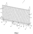
Fig. 2 ] Lafigure 2 est une vue en perspective d'un élément modulaire pour l'obtention du support de coupe de lafigure 1 .[Fig. 2 ] Therefigure 2 is a perspective view of a modular element for obtaining the cutting support of thefigure 1 . -
[
Fig. 3 ] Lafigure 3 est une vue de face de l'élément modulaire de lafigure 2 .[Fig. 3 ] ThereFigure 3 is a front view of the modular element of thefigure 2 . -
[
Fig. 4 ] Lafigure 4 est une vue de côté de l'élément modulaire de lafigure 2 .[Fig. 4 ] ThereFigure 4 is a side view of the modular element of thefigure 2 . -
[
Fig. 5 ] Lafigure 5 est une vue en perspective d'un pavé de support de coupe selon un autre mode de réalisation de l'invention (configuration dite « en quinconce »).[Fig. 5 ] ThereFigure 5 is a perspective view of a cutting support block according to another embodiment of the invention (so-called “staggered” configuration). -
[
Fig. 6 ] Lafigure 6 est une vue partielle et de dessus du pavé de support de coupe de lafigure 5 .[Fig. 6 ] ThereFigure 6 is a partial top view of the cutting support pad of thefigure 5 . -
[
Fig. 7 ] Lafigure 7 est une vue en perspective d'un élément modulaire pour l'obtention du pavé de support de coupe de lafigure 5 .[Fig. 7 ] ThereFigure 7 is a perspective view of a modular element for obtaining the cutting support block of thefigure 5 . -
[
Fig. 8 ] Lafigure 8 est une vue d'une tête de poil d'élément modulaire selon une variante de réalisation.[Fig. 8 ] Therefigure 8 is a view of a modular element hair head according to an alternative embodiment. -
[
Fig. 9 ] Lafigure 9 est une vue en perspective d'un élément modulaire selon encore une variante de réalisation de l'invention.[Fig. 9 ] ThereFigure 9 is a perspective view of a modular element according to yet another alternative embodiment of the invention. -
[
Fig. 10A ] Lafigure 10A montre une variante d'arrangement des poils d'un même élément modulaire selon l'invention.[Fig. 10A ] ThereFigure 10A shows a variant of arrangement of the bristles of the same modular element according to the invention. -
[
Fig. 10B ] Lafigure 10B montre une autre variante d'arrangement des poils d'un même élément modulaire selon l'invention.[Fig. 10B ] ThereFigure 10B shows another variant of arrangement of the bristles of the same modular element according to the invention. -
[
Fig. 11 ] Lafigure 11 est une vue en perspective d'un élément modulaire selon l'invention dépourvu d'organe d'assemblage mécanique.[Fig. 11 ] ThereFigure 11 is a perspective view of a modular element according to the invention without a mechanical assembly member. -
[
Fig. 12 ] Lafigure 12 est une vue partielle d'un élément modulaire selon encore une autre variante de réalisation de l'invention.[Fig. 12 ] ThereFigure 12 is a partial view of a modular element according to yet another alternative embodiment of the invention.
Le convoyeur d'une machine de coupe à lame vibrante permet d'entraîner le matériau à découper durant l'opération de coupe. La partie supérieure du convoyeur sert de support de coupe et la partie inférieure est généralement logée dans un caisson à l'intérieur duquel est établie une forte dépression afin de maintenir immobiles le matériau à découper durant l'opération de coupe.The conveyor of a vibrating blade cutting machine allows the material to be cut to be carried during the cutting operation. The upper part of the conveyor serves as a cutting support and the lower part is generally housed in a box inside which a strong depression is established in order to keep the material to be cut stationary during the cutting operation.
Le support de coupe à proprement peut être typiquement constitué d'un assemblage d'une pluralité de pavés montés sur une courroie d'entraînement tels que le pavé de support de coupe 2 représenté sur la
Ce pavé de support de coupe 2 se compose de l'assemblage entre eux d'une pluralité d'éléments modulaires 4 (par exemple au nombre de onze sur le mode de réalisation représenté par la
Comme représenté plus précisément sur les
Ces poils 6 présentent chacun un pied 8 qui est solidaire d'une semelle 10 commune à l'ensemble des poils, une tête 12 qui est opposée au pied et qui est destinée à servir de support de coupe, et une tige 9 qui relie le pied à la tête.These
Par ailleurs, chaque poil 6 présente la particularité de posséder une tête 12 dont la plus grande section droite (c'est-à-dire la plus grande section réalisée perpendiculairement à l'axe principal du poil) englobe la plus grande section droite de sa tige 9. En d'autres termes, la plus grande section droite de la tête est strictement plus grande que la plus grande section droite de la tige 9 (i.e. elle l'entoure en lui étant plus grande).Furthermore, each
Par exemple, comme représenté sur la
En outre, dans ce mode de réalisation, la tête 12 de chaque poil présente une forme de tronc de cône inversé ayant une section droite circulaire du côté extérieur qui est supérieure à celle du côté intérieur (i.e. la grande base B du tronc de cône est disposée vers l'extérieur de l'élément modulaire et la petite base b du tronc de cône est tournée vers l'intérieur).Furthermore, in this embodiment, the
Bien entendu, l'invention ne se limite pas à ces formes géométriques particulières pour le poil, sa tête et son pied. Par exemple, il est possible d'imaginer que le pied possède une forme de tronc de cône ou de pyramide à base polygonale et la tête présente une section droite autre que circulaire (carrée, hexagonale, etc.).Of course, the invention is not limited to these particular geometric shapes for the hair, its head and its foot. For example, it is possible to imagine that the foot has the shape of a truncated cone or pyramid with a polygonal base and the head has a straight section other than circular (square, hexagonal, etc.).
Afin de permettre l'assemblage mécanique de plusieurs éléments modulaires 4 entre eux, la semelle 10 de chacun d'entre eux peut comprendre, au niveau de chacune de ses deux faces latérales 10a, 10b, au moins un organe d'assemblage mécanique 13 avec un autre élément modulaire.In order to allow the mechanical assembly of several
Par exemple, chacune des faces latérales 10a, 10b de la semelle d'un élément modulaire peut être munie de quatre organes d'assemblage mécanique espacés les uns des autres, à savoir : un organe d'assemblage d'extrémité 13a à chacune de ses extrémités longitudinales 10c, 10d et deux organes d'assemblage centraux 13b positionnés entre ses extrémités longitudinales.For example, each of the lateral faces 10a, 10b of the sole of a modular element can be provided with four mechanical assembly members spaced from each other, namely: an
Toujours à titre d'exemple non limitatif, les organes d'assemblage 13 des deux faces latérales d'un élément modulaire peuvent être alignés les uns en face des autres.Still by way of non-limiting example, the
Comme représenté plus précisément sur l'exemple de la
Lors de l'assemblage mécanique de deux éléments modulaires entre eux, les ergots 14 des organes d'assemblage mécanique de l'un des éléments modulaires viennent s'emboîter à l'intérieur des évidements 16 des organes d'assemblage mécanique de l'autre élément modulaire (et réciproquement) avec un maintien pouvant être assuré par une colle ou par clipsage par exemple. L'assemblage entre eux de plusieurs éléments modulaires permet d'assurer une continuité de la face supérieure de la semelle.During the mechanical assembly of two modular elements together, the
Alternativement, les éléments modulaires pourraient être simplement positionnés les uns à côté des autres sur un pavé ou directement sur un support et maintenus entre eux par un mécanisme adéquat.Alternatively, the modular elements could simply be positioned next to each other on a paving stone or directly on a support and held together by a suitable mechanism.
Toujours selon l'invention, les deux faces latérales 10a, 10b de la semelle 10 de l'élément modulaire comprennent chacune une pluralité de canaux transversaux 18 qui font communiquer la face extérieure de la semelle (c'est-à-dire la face à partir de laquelle s'étendent les poils) avec sa face intérieure (c'est-à-dire la face opposée à la face extérieure).Still according to the invention, the two
Ces canaux transversaux 18 qui sont avantageusement régulièrement répartis sur toute la longueur de la semelle permettent de donner une porosité à la semelle en permettant à l'air d'aspiration de passer au travers de la semelle.These
A titre d'exemple, les canaux transversaux 18 peuvent présenter chacun une section droite de forme semi-circulaire de façon à former des passages transversaux de forme cylindrique lorsque deux éléments modulaires sont montés l'un contre l'autre.For example, the
Bien entendu, il est possible d'envisager une forme différente pour la section droite des canaux transversaux, par exemple une forme elliptique, polygonale ou autre.Of course, it is possible to envisage a different shape for the straight section of the transverse channels, for example an elliptical, polygonal or other shape.
Selon une disposition avantageuse, la semelle 10 de l'élément modulaire comprend en outre, au niveau de chacune de ses deux faces latérales 10a, 10b, un canal longitudinal 20 qui s'étend entre ses deux extrémités longitudinales 10c, 10d et qui communique avec les canaux transversaux 18 afin de répartir de façon homogène l'air d'aspiration dans ces derniers.According to an advantageous arrangement, the sole 10 of the modular element further comprises, at each of its two
A titre d'exemple, le canal longitudinal 20 peut présenter une section droite de forme semi-circulaire de façon à former un passage longitudinal de forme cylindrique lorsque deux éléments modulaires sont montés l'un contre l'autre.For example, the
Bien entendu, il est possible d'envisager une forme différente pour la section droite du canal longitudinal, par exemple une forme elliptique, polygonale ou autre.Of course, it is possible to envisage a different shape for the straight section of the longitudinal channel, for example an elliptical, polygonal or other shape.
Selon une autre disposition avantageuse, la semelle 10 de l'élément modulaire comprend en outre au moins une attache 22 en forme de crochet à chacune de ses extrémités longitudinales 10c, 10d, et deux doigts 24 faisant saillie vers l'intérieur de la semelle.According to another advantageous arrangement, the sole 10 of the modular element further comprises at least one hook-shaped
Les attaches 22 en forme de crochets permettent de monter le pavé de support de coupe formé par l'assemblage de plusieurs éléments modulaires sur un support (non représenté) destiné à être monté directement sur la courroie d'entraînement du convoyeur de coupe. Quant aux doigts 24, ils jouent le rôle de centreurs sur le support.The hook-shaped
Bien entendu, il est possible d'envisager d'autres formes d'attaches pour permettre de monter les éléments modulaires sur un pavé ou directement sur un support de coupe. Par exemple, ces attaches pourraient avoir une forme de T.Of course, it is possible to consider other forms of attachments to allow the modular elements to be mounted on a paving stone or directly on a cutting support. For example, these fasteners could have a T shape.
Dans le mode de réalisation des
Dans un autre mode de réalisation représenté par les
Ainsi, dans le pavé 2' représenté sur les
La
Par rapport au mode de réalisation des
En effet, dans ce mode de réalisation, les canaux transversaux 18' de l'élément modulaire 4' présentent chacun une section droite en forme de double demi-cercle de façon à former des passages transversaux 26 en forme de haricot lorsqu'un autre élément modulaire est assemblé sur ledit élément (voir la
Par ailleurs, un canal longitudinal 20' s'étendant entre les extrémités longitudinales de la semelle communique avec les canaux transversaux 18' afin de répartir de façon homogène l'air d'aspiration dans ces derniers.Furthermore, a longitudinal channel 20' extending between the longitudinal ends of the sole communicates with the transverse channels 18' in order to distribute the suction air evenly in the latter.
La
Dans cette variante de réalisation, la tête 12' des poils 6' possède une forme de tronc de cône ayant une section droite circulaire du côté intérieur qui est supérieure à celle du côté extérieur (i.e. la petite base b' du tronc de cône est disposée vers l'extérieur de l'élément modulaire et la grande base B' du tronc de cône est tournée vers l'intérieur).In this variant embodiment, the head 12' of the bristles 6' has the shape of a truncated cone having a circular cross section on the inner side which is greater than that on the outer side (ie the small base b ' of the truncated cone is arranged towards the exterior of the modular element and the large base B 'of the truncated cone is turned inwards).
Dans cette variante de réalisation, la tête 12' présente également une section droite circulaire dont la plus grande section droite (c'est-à-dire au niveau de la grande base B') présente un diamètre D' qui est strictement supérieur au plus grand diamètre d' de la section droite circulaire de la tige 9' du poil.In this variant embodiment, the head 12' also has a circular cross section, the largest cross section of which (that is to say at the level of the large base B ') has a diameter D' which is strictly greater than the largest large diameter of the circular straight section of the hair shaft 9'.
Par ailleurs, quelle que soit la variante de réalisation des poils des éléments modulaires 4, 4', la tige 9, 9' de chaque poil 6, 6' peut présenter une forme cylindrique entre sa tête 12, 12' et son pied 8, 8'. Bien entendu, toute autre forme est également envisageable (par exemple avec une section droite carrée, polygonale, etc.).Furthermore, whatever the alternative embodiment of the bristles of the
Ainsi, la
Une telle forme générale des poils 6, 6', 6" et la réalisation d'éléments modulaires comprenant des rangées uniques de poils permet de fabriquer ces derniers par moulage en une seule pièce. En particulier, une telle configuration permet de s'affranchir des contraintes de forme de poils que nécessitait le démoulage.Such a general shape of the
Bien entendu, il est possible d'envisager un autre mode de fabrication des éléments modulaires, par exemple par fabrication additive ou tout autre procédé industriel de fabrication.Of course, it is possible to consider another method of manufacturing modular elements, for example by additive manufacturing or any other industrial manufacturing process.
On notera encore que tous les poils d'un même élément modulaire n'ont pas nécessairement une tête dont la section droite englobe la plus grande section droite de la tige. Il est en effet possible d'envisager que seuls certains poils d'un même élément modulaire présentent une telle caractéristique, les autres poils de l'élément modulaire ayant une tête de section droite identique à celle de leur tige.It will also be noted that all the hairs of the same modular element do not necessarily have a head whose cross section includes the largest cross section of the rod. It is in fact possible to envisage that only certain bristles of the same modular element have such a characteristic, the other bristles of the modular element having a head of straight section identical to that of their stem.
Par ailleurs, les
Sur l'exemple d'arrangement de la
Alternativement, sur l'exemple de réalisation de la
Quelle que soit la variante de réalisation, on notera que l'élément modulaire peut être fabriqué par moulage en une seule pièce.Whatever the alternative embodiment, it will be noted that the modular element can be manufactured by molding in a single piece.
De même, comme représenté sur la
La
Ainsi, sur l'exemple de réalisation de la
Une telle alternance « en tête-bêche » des têtes de poils a pour avantage d'augmenter la densité apparente de poils, ce qui permet d'accroître le maintien du tissu.Such a “head-to-tail” alternation of the hair heads has the advantage of increasing the apparent density of the hairs, which makes it possible to increase the hold of the fabric.
Bien entendu, il est possible d'envisager toute autre configuration possible (avec plusieurs formes différentes de têtes de poils) en fonction des besoins. De même, cette variante de réalisation peut être associée aux autres variantes de réalisation précédemment décrite.Of course, it is possible to consider any other possible configuration (with several different shapes of bristle heads) depending on needs. Likewise, this alternative embodiment can be associated with the other alternative embodiments previously described.
Claims (20)
- A modular element (4; 4'; 4"; 4"') of a cutting support (2; 2') with suction in a machine for automatic cutting of sheet material by means of blades, comprising a plurality of bristles (6; 6'; 6"; 6a-6b) arranged in the same single line (L1; L2), at least some bristles each having a base (8; 8'; 8") rigidly connected to a bearing plate (10) intended to be mounted on a support, a head (12; 12'; 12"; 12a-12b) opposite the base on which a sheet material to be cut is intended to rest, and a stem (9; 9'; 9") connecting the head to the base, the largest cross-section of which is strictly included in the largest cross-section of the head, the bearing plate comprising, on each of its side surfaces (10a, 10b), a plurality of transverse channels (18; 18') for the passage of suction air providing communication between an upper surface of the bearing plate from which the bristles extend and an inner surface opposite the upper surface.
- The modular element according to claim 1, wherein the bearing plate (10) further comprises, at each of its side surfaces (10a, 10b), at least one longitudinal channel (20; 20') extending between the longitudinal ends (10c, 10d) of the bearing plate and communicating with the transverse channels (18; 18') in order to uniformly distribute suction air in said transverse channels.
- The modular element according to one of claims 1 and 2, wherein the bearing plate further comprises, at each of its side surfaces, at least one member (13) for mechanical assembly with another modular element.
- The modular element according to claim 3, wherein each assembly member (13) comprises at least one lug (14) protruding with respect to a side surface (10a, 10b) of the bearing plate and intended to interlock into a corresponding recess of an assembly member of an adjacent modular element, and a recess (16) set back with respect to the side surface of the bearing plate and intended to receive, by interlocking, a corresponding lug of the assembly member of the adjacent modular element.
- The modular element according to any one of claims 1 to 4, wherein at least some bristles (6; 6') comprise a head (12; 12') having a conical frustum shape and a stem (9; 9') having a cylindrical shape.
- The modular element according to claim 5, wherein the head (12') of each bristle (6') has a conical frustum shape having a circular cross-section on the inner side which is greater than that on the outer side.
- The modular element according to claim 5, wherein the head (12) of each bristle (6) has a reversed conical frustum shape having a circular cross-section on the outer side which is greater than that on the inner side.
- The modular element according to any one of claims 1 to 4, wherein at least some bristles (6") have a stem (9") and a head (12") with a polygonal cross-section.
- The modular element according to claim 8, wherein the stem (9") of the bristles has a hexagonal cross-section and the head (12") of said bristles has an octagonal cross-section.
- The modular element according to any one of claims 1 to 9, wherein the bearing plate (10) further comprises an attachment (22) at each longitudinal end for assembling the modular element on a support and two fingers (24) projecting inwards and acting as centring elements on the support.
- The modular element according to any one of claims 1 to 10, wherein the transverse channels (18) have a semicircular cross-section so as to form cylindrical transverse passages when another modular element is mounted against said element.
- The modular element according to any one of claims 1 to 11, wherein said element is obtained by moulding.
- The modular element according to any one of claims 1 to 12, wherein the bristles (6; 6'; 6") are arranged in a straight line (L1) forming a single row of bristles.
- The modular element according to any one of claims 1 to 12, wherein the bristles (6; 6'; 6") are arranged in a broken line (L2) forming two parallel rows (R1, R2) of bristles.
- The modular element (4‴) according to any one of claims 1 to 14, comprising at least two bristles (6a, 6b) for which the respective heads (12a, 12b) have different shapes.
- A cutting support (2; 2') with suction in a machine for automatic cutting of sheet material comprising a plurality of modular elements (4; 4') according to any one of claims 1 to 15 mounted on at least one support.
- The cutting support (2) according to claim 16, wherein the modular elements (4) are mounted on the support so as to obtain an ordered alignment of the bristles.
- The cutting support (2) according to claim 16, wherein the modular elements (4') are mounted on the support so as to obtain a staggered alignment of the bristles.
- The cutting support according to claim 16, wherein some modular elements are mounted on the support so as to obtain an ordered alignment of the bristles and some other modular elements are mounted on the same support so as to obtain a staggered alignment of the bristles.
- The cutting support according to any one of claims 16 to 19, wherein the distance between two adjacent bristles is greater than the largest dimension of the cross-section of the stem of the bristles.
Applications Claiming Priority (2)
| Application Number | Priority Date | Filing Date | Title |
|---|---|---|---|
| FR2003043A FR3108547B1 (en) | 2020-03-27 | 2020-03-27 | Modular suction cutting support element of an automatic sheet material cutting machine |
| PCT/FR2021/050407 WO2021191522A1 (en) | 2020-03-27 | 2021-03-10 | Modular support element for aspirated cutting in a machine for automatic cutting of sheet material |
Publications (2)
| Publication Number | Publication Date |
|---|---|
| EP4096885A1 EP4096885A1 (en) | 2022-12-07 |
| EP4096885B1 true EP4096885B1 (en) | 2024-02-21 |
Family
ID=70614286
Family Applications (1)
| Application Number | Title | Priority Date | Filing Date |
|---|---|---|---|
| EP21716799.8A Active EP4096885B1 (en) | 2020-03-27 | 2021-03-10 | Modular element for suction cutting bed in an automatic machine for cutting sheet material |
Country Status (8)
| Country | Link |
|---|---|
| US (1) | US20230114746A1 (en) |
| EP (1) | EP4096885B1 (en) |
| JP (1) | JP2023518557A (en) |
| CN (1) | CN115884860A (en) |
| BR (1) | BR112022018940A2 (en) |
| FR (1) | FR3108547B1 (en) |
| MX (1) | MX2022011802A (en) |
| WO (1) | WO2021191522A1 (en) |
Families Citing this family (1)
| Publication number | Priority date | Publication date | Assignee | Title |
|---|---|---|---|---|
| FR3134328B1 (en) | 2022-04-07 | 2024-04-05 | Lectra | device for assembling a cutting support element on a slat of a conveyor cutting machine |
Family Cites Families (2)
| Publication number | Priority date | Publication date | Assignee | Title |
|---|---|---|---|---|
| US4205835A (en) | 1977-05-13 | 1980-06-03 | Gerber Garment Technology, Inc. | Bristle bed for vacuum table |
| ITMI20011626A1 (en) * | 2001-07-26 | 2003-01-26 | Matteo Zanesi | ASPIRATNE ASSEMBLY FOR CUTTING PLAN OF MACHINES FOR CUTTING SHEET MATERIALS |
-
2020
- 2020-03-27 FR FR2003043A patent/FR3108547B1/en active Active
-
2021
- 2021-03-10 CN CN202180023614.XA patent/CN115884860A/en active Pending
- 2021-03-10 JP JP2022557644A patent/JP2023518557A/en active Pending
- 2021-03-10 BR BR112022018940A patent/BR112022018940A2/en unknown
- 2021-03-10 US US17/914,226 patent/US20230114746A1/en active Pending
- 2021-03-10 WO PCT/FR2021/050407 patent/WO2021191522A1/en unknown
- 2021-03-10 MX MX2022011802A patent/MX2022011802A/en unknown
- 2021-03-10 EP EP21716799.8A patent/EP4096885B1/en active Active
Also Published As
| Publication number | Publication date |
|---|---|
| CN115884860A (en) | 2023-03-31 |
| MX2022011802A (en) | 2023-03-06 |
| JP2023518557A (en) | 2023-05-02 |
| BR112022018940A2 (en) | 2022-12-13 |
| US20230114746A1 (en) | 2023-04-13 |
| FR3108547A1 (en) | 2021-10-01 |
| WO2021191522A1 (en) | 2021-09-30 |
| EP4096885A1 (en) | 2022-12-07 |
| FR3108547B1 (en) | 2022-04-01 |
Similar Documents
| Publication | Publication Date | Title |
|---|---|---|
| EP1564141B1 (en) | Aircraft seat rail and its production method | |
| FR2953681A1 (en) | SUSPENSION DEVICE FOR AGRICULTURAL MACHINE | |
| CA2714270C (en) | Anchor for handling construction elements comprising fixed divergent arms | |
| EP4096885B1 (en) | Modular element for suction cutting bed in an automatic machine for cutting sheet material | |
| EP1585615B1 (en) | Slat for laser cutting machine table | |
| EP1810560B1 (en) | Semi-hollow tyre for a farming machine | |
| EP3114916B1 (en) | Furrow-opening tire | |
| EP3017669B1 (en) | Improved agricultural wheel | |
| FR2527415A1 (en) | METHOD FOR MANUFACTURING ROTARY HARBOR TEETH | |
| FR2730378A1 (en) | MACHINE FOR AUTOMATIC OR SEMI-AUTOMATIC PRE-TAILING OR PRUNING OF VINES AND PALISSE TREES OR TREES | |
| FR3069726A1 (en) | CAGE ROTOR INJECTED | |
| EP4139101A1 (en) | Suction cutting conveyor for an automatic blade cutting machine for sheet materials | |
| EP2269431B1 (en) | Roller with semi-hollow tyres, in particular for farming machines | |
| EP2382860A1 (en) | Pre-pruner | |
| EP3112793B1 (en) | Device for dispensing falling film on a plate cooler comprising first and second distribution stages | |
| EP3459349A1 (en) | Agricultural machine for the transport and distribution of bulk products | |
| FR2776239A1 (en) | Special tires mounted on tube to form roller creating furrows for seed drill | |
| EP1029435A1 (en) | Cutting member of a cutting machine | |
| FR2938726A1 (en) | Disk assembly for roller of agricultural machine, has stiffeners formed on annular sides to increase stiffness of solid band in direction parallel to axis of tube and to confer flexibility in direction perpendicular to axis of tube | |
| FR3017147A1 (en) | BOX FOR WAITING BOX AND WAITING BOX PROVIDED WITH SUCH A CAISSON | |
| FR2904023A1 (en) | Modular element for forming concordant screen wall, has bearings threaded on rods that are anchored and raised at ground along pattern for forming wall conformed to chosen pattern by superposing and juxtaposing element with another element | |
| FR3069731A1 (en) | CAGE ROTOR INJECTED | |
| WO2023194686A1 (en) | . device for assembling a cutting-bed support element on a batten of a conveyor-type cutting machine | |
| EP4244029A1 (en) | Modular comb element for a machine for automatic cutting of a mat of sheets of material | |
| EP2026682B1 (en) | Single-piece slat suspension device |
Legal Events
| Date | Code | Title | Description |
|---|---|---|---|
| STAA | Information on the status of an ep patent application or granted ep patent |
Free format text: STATUS: UNKNOWN |
|
| STAA | Information on the status of an ep patent application or granted ep patent |
Free format text: STATUS: THE INTERNATIONAL PUBLICATION HAS BEEN MADE |
|
| PUAI | Public reference made under article 153(3) epc to a published international application that has entered the european phase |
Free format text: ORIGINAL CODE: 0009012 |
|
| STAA | Information on the status of an ep patent application or granted ep patent |
Free format text: STATUS: REQUEST FOR EXAMINATION WAS MADE |
|
| 17P | Request for examination filed |
Effective date: 20220829 |
|
| AK | Designated contracting states |
Kind code of ref document: A1 Designated state(s): AL AT BE BG CH CY CZ DE DK EE ES FI FR GB GR HR HU IE IS IT LI LT LU LV MC MK MT NL NO PL PT RO RS SE SI SK SM TR |
|
| DAV | Request for validation of the european patent (deleted) | ||
| DAX | Request for extension of the european patent (deleted) | ||
| GRAP | Despatch of communication of intention to grant a patent |
Free format text: ORIGINAL CODE: EPIDOSNIGR1 |
|
| STAA | Information on the status of an ep patent application or granted ep patent |
Free format text: STATUS: GRANT OF PATENT IS INTENDED |
|
| INTG | Intention to grant announced |
Effective date: 20230927 |
|
| GRAS | Grant fee paid |
Free format text: ORIGINAL CODE: EPIDOSNIGR3 |
|
| GRAA | (expected) grant |
Free format text: ORIGINAL CODE: 0009210 |
|
| STAA | Information on the status of an ep patent application or granted ep patent |
Free format text: STATUS: THE PATENT HAS BEEN GRANTED |
|
| AK | Designated contracting states |
Kind code of ref document: B1 Designated state(s): AL AT BE BG CH CY CZ DE DK EE ES FI FR GB GR HR HU IE IS IT LI LT LU LV MC MK MT NL NO PL PT RO RS SE SI SK SM TR |
|
| REG | Reference to a national code |
Ref country code: GB Ref legal event code: FG4D Free format text: NOT ENGLISH |
|
| RIN1 | Information on inventor provided before grant (corrected) |
Inventor name: BEN GHORBAL, GHAILEN Inventor name: REGNIER, GILLES Inventor name: LALLEMENT, REGIS Inventor name: CHABIRAND, DIDIER |
|
| REG | Reference to a national code |
Ref country code: CH Ref legal event code: EP |
|
| REG | Reference to a national code |
Ref country code: IE Ref legal event code: FG4D Free format text: LANGUAGE OF EP DOCUMENT: FRENCH |
|
| REG | Reference to a national code |
Ref country code: DE Ref legal event code: R096 Ref document number: 602021009629 Country of ref document: DE |
|
| PGFP | Annual fee paid to national office [announced via postgrant information from national office to epo] |
Ref country code: LT Payment date: 20240306 Year of fee payment: 4 |
|
| PGFP | Annual fee paid to national office [announced via postgrant information from national office to epo] |
Ref country code: NL Payment date: 20240322 Year of fee payment: 4 |