EP4096885B1 - Modulares element für saugschneidfläche für eine maschine für das automatische schneiden von blättern - Google Patents
Modulares element für saugschneidfläche für eine maschine für das automatische schneiden von blättern Download PDFInfo
- Publication number
- EP4096885B1 EP4096885B1 EP21716799.8A EP21716799A EP4096885B1 EP 4096885 B1 EP4096885 B1 EP 4096885B1 EP 21716799 A EP21716799 A EP 21716799A EP 4096885 B1 EP4096885 B1 EP 4096885B1
- Authority
- EP
- European Patent Office
- Prior art keywords
- bristles
- modular element
- modular
- support
- head
- Prior art date
- Legal status (The legal status is an assumption and is not a legal conclusion. Google has not performed a legal analysis and makes no representation as to the accuracy of the status listed.)
- Active
Links
- 238000005520 cutting process Methods 0.000 title claims description 61
- 239000000463 material Substances 0.000 title claims description 21
- 238000000465 moulding Methods 0.000 claims description 5
- 210000004209 hair Anatomy 0.000 description 32
- 238000004519 manufacturing process Methods 0.000 description 7
- 239000004575 stone Substances 0.000 description 4
- 230000000149 penetrating effect Effects 0.000 description 3
- 210000004919 hair shaft Anatomy 0.000 description 2
- 239000004753 textile Substances 0.000 description 2
- 241000549893 Carphochaete Species 0.000 description 1
- 235000010627 Phaseolus vulgaris Nutrition 0.000 description 1
- 244000046052 Phaseolus vulgaris Species 0.000 description 1
- 239000000654 additive Substances 0.000 description 1
- 230000000996 additive effect Effects 0.000 description 1
- 239000004744 fabric Substances 0.000 description 1
- 239000003292 glue Substances 0.000 description 1
- 230000003993 interaction Effects 0.000 description 1
- 238000000034 method Methods 0.000 description 1
Images


Classifications
-
- B—PERFORMING OPERATIONS; TRANSPORTING
- B26—HAND CUTTING TOOLS; CUTTING; SEVERING
- B26D—CUTTING; DETAILS COMMON TO MACHINES FOR PERFORATING, PUNCHING, CUTTING-OUT, STAMPING-OUT OR SEVERING
- B26D7/00—Details of apparatus for cutting, cutting-out, stamping-out, punching, perforating, or severing by means other than cutting
- B26D7/01—Means for holding or positioning work
- B26D7/018—Holding the work by suction
-
- B—PERFORMING OPERATIONS; TRANSPORTING
- B26—HAND CUTTING TOOLS; CUTTING; SEVERING
- B26D—CUTTING; DETAILS COMMON TO MACHINES FOR PERFORATING, PUNCHING, CUTTING-OUT, STAMPING-OUT OR SEVERING
- B26D7/00—Details of apparatus for cutting, cutting-out, stamping-out, punching, perforating, or severing by means other than cutting
- B26D7/06—Arrangements for feeding or delivering work of other than sheet, web, or filamentary form
- B26D7/0625—Arrangements for feeding or delivering work of other than sheet, web, or filamentary form by endless conveyors, e.g. belts
-
- B—PERFORMING OPERATIONS; TRANSPORTING
- B26—HAND CUTTING TOOLS; CUTTING; SEVERING
- B26D—CUTTING; DETAILS COMMON TO MACHINES FOR PERFORATING, PUNCHING, CUTTING-OUT, STAMPING-OUT OR SEVERING
- B26D7/00—Details of apparatus for cutting, cutting-out, stamping-out, punching, perforating, or severing by means other than cutting
- B26D7/20—Cutting beds
Definitions
- the present invention relates to a suction cutting support for an automatic cutting machine for sheet materials, in particular textile materials, using a vibrating blade penetrating into the cutting support. It concerns more precisely a modular element intended to form such a cutting support.
- One field of application of the invention is that of the automatic cutting of stacks or mats of sheets of materials, in particular textile materials, using a vibrating blade penetrating into a suction cutting support.
- a vibrating blade cutting machine typically includes a cutting conveyor which serves to drive the stack of sheets during the cutting operation.
- This cutting conveyor is housed in a box inside which a strong depression is established in order to keep the sheets of material to be cut stationary during the cutting operation.
- the cutting conveyor also serves as a penetrating cutting support for the vibrating blade. It is in fact well known to make the cutting support penetrable by the blade so that during the cutting operation, the blade can not only completely pass through the material to be cut, but also extend downward beyond the support surface and in the bed of material providing such a surface.
- the cutting support is generally made up of an assembly of blocks driven by a belt. More precisely, each block comprises a plurality of bristles mounted on a sole in several parallel rows, each bristle having a head forming the support for the sheet material to be cut. Transverse channels are made through the sole to allow the passage of suction air. These blocks thus make it possible to support the material to be cut under suction while being able to be penetrated by the cutting blade.
- Cutting support blocks are most often obtained by molding plastic material. Molding makes it possible to obtain a paving stone in one piece with the sole and all of its bristles. To ensure the unmolding of such a part, it is necessary that the bristles, which generally have a conical or cylindrical shape, have a head diameter smaller than the base diameter. We can in particular refer to the document US 4,205,835 which describes an exemplary embodiment of such a cutting support block.
- the tip of the cutting blades being beveled, the interference between the blade and the hairs is favored by the conicity of the hairs associated with their flexibility, which can result in partial or total cuts of hairs.
- the height position of this cut is directly linked to the conicity of the hairs and the blade or the position of the blade in relation to the generator of the hairs encountered by the blade.
- the need to have bristles whose foot has a larger diameter than the head has the disadvantage of limiting the space on the sole to make the passage channels for the suction air, which reduces as much as the suction capacity of the cutting support.
- a modular suction cutting support element of an automatic blade cutting machine for sheet materials comprising a plurality of bristles arranged in the same and single line, at least certain bristles each having a foot secured to a sole intended to be mounted on a support, an end opposite the foot on which is intended to rest a sheet material to be cut, and a rod connecting the head to the foot, the sole comprising, at each of its lateral faces, a plurality transverse channels for the passage of suction air communicating an upper face of the sole from which the bristles extend with an inner face opposite the upper face.
- the invention therefore aims to propose a cutting support which does not present the aforementioned drawbacks.
- a modular suction cutting support element of an automatic blade cutting machine for sheet materials comprising a plurality of bristles arranged along the same and single line, at least certain hairs each having a foot attached to a sole intended to be mounted on a support, a head opposite the foot on which is intended to rest a sheet material to be cut, and a rod connecting the head to the foot and the largest straight section of which is strictly included in the largest straight section of the head, the sole comprising, at each of its lateral faces, a plurality of transverse channels for the passage of suction air causing an upper face of the sole from which the bristles extend to communicate with an inner face opposite the upper face.
- straight section here we mean a section made perpendicular to the axis of the hair.
- strictly included we mean here that all the points of the largest straight section of the shaft of each hair are included (or encompassed) in the largest straight section of the head of the hair but that at least a point of the largest cross section of the head is not included in the largest cross section of the rod.
- this condition is equivalent to the cross section of the head having a diameter strictly greater than that of the shaft.
- the invention is remarkable in that it makes it possible to produce cutting supports by mounting a plurality of modular elements on at least one support.
- each modular element comprises bristles arranged along the same and single line, it is possible to give at least certain bristles a head having a straight section encompassing a straight section of the rod, while retaining the ability to manufacture these modular elements by molded in one piece with their sole and their hairs.
- Such a geometric shape of the bristles has the advantage of limiting interactions between the tip of the cutting blade and the tangent bristles.
- the support surface offered by these modular elements is better due to the fact that the head of the bristles has a larger cross section than that of the rods.
- the cross section of the rods and feet of the bristles it is easier to increase the diameter of the transverse channels for the passage of suction air, and thus to improve the air porosity of the sole in order to maintain maximum suction and limit pressure losses.
- Another advantage linked to the production of cutting supports by mounting a plurality of modular elements according to the invention lies in the possibility of being able to offer cutting supports differentiated by cutting blade, professions, etc.
- the sole further comprises, at each of its lateral faces, at least one longitudinal channel extending between the ends longitudinal of the sole and communicating with the transverse channels in order to distribute the suction air evenly in the transverse channels.
- This characteristic makes it possible to make the suction of the modular element more homogeneous over the entire surface of the sole.
- the sole further comprises, at each of its lateral faces, at least one mechanical assembly member with another modular element.
- each mechanical assembly member may comprise at least one lug projecting relative to a side face of the sole and intended to fit into a corresponding recess of an assembly member of a modular element adjacent, and a recess set back from the side face of the sole and intended to receive by nesting a corresponding lug of the assembly member of the adjacent modular element.
- At least some hairs may include a head having a truncated cone shape and a shaft having a cylindrical shape.
- the head of these hairs may have the shape of a truncated cone having a circular cross section on the inner side which is greater than that on the outer side.
- the head of these hairs may have the shape of an inverted truncated cone having a circular cross section on the exterior side which is greater than that on the interior side.
- At least certain hairs may have a rod and a head having a straight section of polygonal shape, for example a rod of straight section of hexagonal shape and a head of straight section of octagonal shape.
- the sole may further comprise a fastener at each longitudinal end for assembling the modular element on a support, and two fingers projecting inwards and acting as centralizers on the support.
- the transverse channels can have a cross section of semi-circular shape so as to form transverse passages of cylindrical shape when another modular element is mounted against said element.
- the bristles of the same modular element can be arranged in a straight line forming a single row of bristles.
- the bristles can be arranged in a broken line forming two parallel rows of bristles.
- the modular element may comprise at least two bristles whose respective heads have different shapes.
- the invention also relates to a suction cutting support for an automatic cutting machine for sheet materials comprising a plurality of modular elements as defined above and mounted on at least one support.
- the modular elements can be mounted on the support so as to obtain an orderly alignment of the bristles.
- modular elements can be mounted on the support so as to obtain a staggered alignment of the bristles.
- certain modular elements are mounted on the support so as to obtain an orderly alignment of the bristles and certain other modular elements are mounted on the same support so as to obtain a staggered alignment of the bristles.
- the distance between two adjacent hairs is greater than the largest dimension of the cross section of the hair shaft. This characteristic prevents a cut hair coming from the bottom of the paving stone from separating the surrounding hairs.
- the conveyor of a vibrating blade cutting machine allows the material to be cut to be carried during the cutting operation.
- the upper part of the conveyor serves as a cutting support and the lower part is generally housed in a box inside which a strong depression is established in order to keep the material to be cut stationary during the cutting operation.
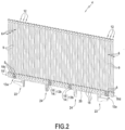
- the actual cutting support may typically consist of an assembly of a plurality of blocks mounted on a drive belt such as the cutting support block 2 shown on the figure 1 .
- This cutting support block 2 consists of the assembly between them of a plurality of modular elements 4 (for example eleven in number in the embodiment represented by the figure 1 ).
- the modular elements are assembled together by interlocking their respective side faces as described below.
- each modular element 4 comprises a plurality of bristles 6 which are aligned in the same and single row of bristles.
- These bristles 6 each have a foot 8 which is secured to a sole 10 common to all of the bristles, a head 12 which is opposite the foot and which is intended to serve as a cutting support, and a rod 9 which connects the foot to head.
- each hair 6 has the particularity of having a head 12 whose largest straight section (that is to say the largest section made perpendicular to the main axis of the hair) encompasses the largest straight section of its stem 9.
- the largest cross section of the head is strictly larger than the largest cross section of stem 9 (i.e. it surrounds it while being larger).
- the largest straight section of the head has a diameter D which is strictly greater than the largest diameter d of the straight section of the rod.
- the head 12 of each hair has the shape of an inverted truncated cone having a circular cross section on the outer side which is greater than that on the inner side (i.e. the large base B of the truncated cone is arranged towards the outside of the modular element and the small base b of the truncated cone is turned towards the inside).
- the invention is not limited to these particular geometric shapes for the hair, its head and its foot.
- the foot has the shape of a truncated cone or pyramid with a polygonal base and the head has a straight section other than circular (square, hexagonal, etc.).
- the sole 10 of each of them can comprise, at each of its two lateral faces 10a, 10b, at least one mechanical assembly member 13 with another modular element.
- each of the lateral faces 10a, 10b of the sole of a modular element can be provided with four mechanical assembly members spaced from each other, namely: an end assembly member 13a at each of its longitudinal ends 10c, 10d and two central assembly members 13b positioned between its longitudinal ends.
- the assembly members 13 of the two side faces of a modular element can be aligned opposite each other.
- the mechanical assembly members 13 can each comprise at least one lug 14 which projects relative to the side face of the sole and a recess 16 set back relative to the side face of the sole, the lug and the recess being for example positioned transversely one above the other.
- the lugs 14 of the mechanical assembly members of one of the modular elements fit inside the recesses 16 of the mechanical assembly members of the other modular element (and vice versa) with support that can be ensured by glue or by clipping for example.
- the assembly of several modular elements together ensures continuity of the upper face of the sole.
- the modular elements could simply be positioned next to each other on a paving stone or directly on a support and held together by a suitable mechanism.
- the two lateral faces 10a, 10b of the sole 10 of the modular element each comprise a plurality of transverse channels 18 which communicate the exterior face of the sole (that is to say the face to from which the hairs extend) with its interior face (that is to say the face opposite to the exterior face).
- transverse channels 18 which are advantageously regularly distributed over the entire length of the sole make it possible to give porosity to the sole by allowing the suction air to pass through the sole.
- the transverse channels 18 can each have a cross section of semi-circular shape so as to form transverse passages of cylindrical shape when two modular elements are mounted against each other.
- the sole 10 of the modular element further comprises, at each of its two lateral faces 10a, 10b, a longitudinal channel 20 which extends between its two longitudinal ends 10c, 10d and which communicates with the transverse channels 18 in order to distribute the suction air evenly in the latter.
- the longitudinal channel 20 may have a cross section of semi-circular shape so as to form a longitudinal passage of cylindrical shape when two modular elements are mounted against each other.
- the sole 10 of the modular element further comprises at least one hook-shaped fastener 22 at each of its longitudinal ends 10c, 10d, and two fingers 24 projecting towards the inside of the sole.
- the hook-shaped fasteners 22 make it possible to mount the cutting support block formed by the assembly of several modular elements on a support (not shown) intended to be mounted directly on the drive belt of the cutting conveyor. As for the fingers 24, they play the role of centerers on the support.
- the modular elements are assembled within the same block so as to obtain an ordered alignment of the blocks bristles, that is to say that the bristles 6 within the same block 2 are aligned in the longitudinal and transverse directions.
- At least some of the modular elements of the same block can be assembled so as to obtain a staggered alignment of the bristles.
- the modular elements 4-1 to 4-4 are assembled so as to obtain an ordered alignment of the bristles, while the modular elements 4'-1 to 4'-4 are assembled so as to obtain a staggered alignment of the bristles.
- the modular elements 4'-1 to 4'-4 are assembled so as to obtain a staggered alignment of the bristles.
- other configurations are possible depending on needs by mixing the two types of modular elements.
- FIG. 7 represents in detail and in perspective a modular element 4' making it possible to obtain a staggered assembly of the bristles within the same support block.
- this modular element 4' is distinguished by the shape of the transverse channels 18' for the passage of suction air between the interior face and the exterior face of the sole 10.
- the transverse channels 18' of the modular element 4' each have a straight section in the shape of a double semi-circle so as to form transverse passages 26 in the shape of a bean when another element modular is assembled on said element (see the Figure 6 ).
- a longitudinal channel 20' extending between the longitudinal ends of the sole communicates with the transverse channels 18' in order to distribute the suction air evenly in the latter.
- FIG 8 represents a hair head of a modular element according to a variant embodiment, this hair shape being able to be applied equally well to the modular elements of the embodiment of the figures 1 to 4 than those of the mode of realization of the figures 5 to 7 .
- the head 12' of the bristles 6' has the shape of a truncated cone having a circular cross section on the inner side which is greater than that on the outer side (ie the small base b ' of the truncated cone is arranged towards the exterior of the modular element and the large base B 'of the truncated cone is turned inwards).
- the head 12' also has a circular cross section, the largest cross section of which (that is to say at the level of the large base B ') has a diameter D' which is strictly greater than the largest large diameter of the circular straight section of the hair shaft 9'.
- the rod 9, 9' of each bristle 6, 6' can have a cylindrical shape between its head 12, 12' and its foot 8, 8'.
- any other shape is also possible (for example with a square, polygonal cross section, etc.).
- Figure 9 represents yet another alternative embodiment of a modular cutting support element 4" in which the rod 9" of the bristles 6" has a straight section of hexagonal shape between the head 12" and the foot 8". Furthermore, in this alternative embodiment, the 12" head has a straight section of octagonal shape.
- Such a general shape of the bristles 6, 6', 6" and the production of modular elements comprising single rows of bristles makes it possible to manufacture the latter by molding in a single piece.
- such a configuration makes it possible to overcome the hair shape constraints required for demoulding.
- all the hairs of the same modular element do not necessarily have a head whose cross section includes the largest cross section of the rod. It is in fact possible to envisage that only certain bristles of the same modular element have such a characteristic, the other bristles of the modular element having a head of straight section identical to that of their stem.
- FIGS 10A And 10B show two possible arrangements for the bristles 6, 6', 6" of the same modular element 4, 4'.
- the bristles of the same modular element are arranged along a straight line L1 forming a single row of bristles.
- the respective longitudinal axes of the hairs are all aligned on the same straight line L1.
- the bristles of the same modular element can be arranged along a broken (or sawtooth) line L2 so as to form two rows of bristles R1, R2 which are parallel.
- the modular element can be manufactured by molding in a single piece.
- the modular element 4 according to the invention can be devoid of mechanical assembly member.
- the modular elements of the same support are simply positioned against each other on the same support and held together by an appropriate mechanism.
- FIG. 12 illustrates, partially, yet another alternative embodiment of a modular cutting support element 4"' in which the heads of the bristles have different shapes.
- the modular element comprises an alternation of bristles 6a whose respective head 12a has a truncated cone shape whose large base faces outwards and bristles 6b whose respective head 12b has a truncated cone shape whose the large base faces inwards.
- Such a “head-to-tail” alternation of the hair heads has the advantage of increasing the apparent density of the hairs, which makes it possible to increase the hold of the fabric.
Landscapes
- Life Sciences & Earth Sciences (AREA)
- Forests & Forestry (AREA)
- Engineering & Computer Science (AREA)
- Mechanical Engineering (AREA)
- Brushes (AREA)
- Details Of Cutting Devices (AREA)
- Treatment Of Fiber Materials (AREA)
- Feeding Of Articles By Means Other Than Belts Or Rollers (AREA)
Claims (20)
- Modulares Element (4; 4'; 4"; 4‴) einer Ansaug-Schneidunterlage (2; 2') einer Maschine für das automatische Schneiden von Bogenmaterialien mittels Klinge, umfassend mehrere Borsten (6; 6'; 6"; 6a-6b), die gemäß einer gleichen und einzigen Linie (L1; L2) angeordnet sind, wobei mindestens bestimmte Borsten jeweils einen Fuß (8; 8'; 8"), der fest mit einer Druckplatte (10) verbunden ist, die dazu bestimmt ist, auf einer Unterlage montiert zu sein, einen Kopf (12; 12'; 12"; 12a-12b) gegenüber dem Fuß, auf dem ein zuzuschneidendes Bogenmaterial aufliegen soll, und eine Stange (9; 9'; 9") aufweisen, die den Kopf mit dem Fuß verbindet und deren größter Querschnitt strikt in dem größten Querschnitt des Kopfes enthalten ist, wobei die Druckplatte auf der Ebene jeder ihrer Seitenflächen (10a, 10b) mehrere Querkanäle (18; 18') für den Durchgang der Ansaugluft umfasst, wodurch eine obere Fläche der Druckplatte, von welcher sich die Borsten mit einer Innenfläche gegenüber der oberen Fläche erstrecken, in Verbindung tritt.
- Modulares Element nach Anspruch 1, wobei die Druckplatte (10) ferner auf Ebene jeder ihrer Seitenflächen (10a, 10b) mindestens einen Längskanal (20; 20') umfasst, der sich zwischen den Längsenden (10c, 10d) der Druckplatte erstreckt und mit den Querkanälen (18; 18') in Verbindung tritt, um die Ansaugluft in den Querkanälen homogen zu verteilen.
- Modulares Element nach einem der Ansprüche 1 und 2, wobei die Druckplatte ferner auf Ebene jeder ihrer Seitenflächen mindestens ein mechanisches Verbindungsglied (13) mit einem anderen modularen Element umfasst.
- Modulares Element nach Anspruch 3, wobei jedes Verbindungsglied (13) mindestens eine Nase (14) umfasst, die in Bezug auf eine Seitenfläche (10a, 10b) der Druckplatte hervorsteht und dazu bestimmt ist, in eine Aussparung, die einem Verbindungsglied eines benachbarten modularen Elements entspricht, und eine Aussparung (16), die in Bezug auf die Seitenfläche der Druckplatte zurückgesetzt ist, eingefügt zu werden, und dazu bestimmt ist, eine Nase, die dem Verbindungsglied des benachbarten modularen Elements entspricht, durch Einstecken zu empfangen.
- Modulares Element nach einem der Ansprüche 1 bis 4, wobei mindestens bestimmte Borsten (6; 6') einen Kopf (12; 12'), der eine Kegelstumpfform aufweist, und eine Stange (9; 9'), die eine Zylinderform aufweist, umfassen.
- Modulares Element nach Anspruch 5, wobei der Kopf (12') jeder Borste (6') eine Kegelstumpfform mit einem kreisförmigen Querschnitt der Innenseite aufweist, der über jenem der Außenseite liegt.
- Modulares Element nach Anspruch 5, wobei der Kopf (12) jeder Borste (6) eine umgekehrte Kegelstumpfform mit einem kreisförmigen Querschnitt der Außenseite aufweist, der über jenem der Innenseite liegt.
- Modulares Element nach einem der Ansprüche 1 bis 4, wobei mindestens bestimmte Borsten (6") eine Stange (9") und einen Kopf (12") mit einem polygonalen Querschnitt aufweisen.
- Modulares Element nach Anspruch 8, wobei die Stange (9") der Borsten einen sechseckigen Querschnitt aufweist und der Kopf (12") der Borsten einen achteckigen Querschnitt aufweist.
- Modulares Element nach einem der Ansprüche 1 bis 9, wobei die Druckplatte (10) ferner eine Befestigung (22) an jedem Längsende für die Anordnung des modularen Elements auf einer Unterlage und zwei Finger (24), die nach innen vorstehen und die Rolle als Zentriereinrichtungen gegenüber der Unterlage einnehmen, umfasst.
- Modulares Element nach einem der Ansprüche 1 bis 10, wobei die Querkanäle (18) einen halbkreisförmigen Querschnitt derart aufweisen, dass zylinderförmige Querdurchgänge ausgebildet werden, wenn ein anderes modulares Element an dem Element montiert ist.
- Modulares Element nach einem der Ansprüche 1 bis 11, wobei es durch Gießen erlangt wird.
- Modulares Element nach einem der Ansprüche 1 bis 12, wobei die Borsten (6; 6'; 6") gemäß einer geraden Linie (L1), die eine einzige Reihe von Borsten ausbildet, angeordnet sind.
- Modulares Element nach einem der Ansprüche 1 bis 12, wobei die Borsten (6; 6'; 6") gemäß einer gestrichelten Linie (L2), die zwei parallel Reihen (R1, R2) von Borsten ausbildet, angeordnet sind.
- Modulares Element (4‴) nach einem der Ansprüche 1 bis 14, umfassend mindestens zwei Borsten (6a, 6b), deren jeweilige Köpfe (12a, 12b) unterschiedlich geformt sind.
- Ansaug-Schneidunterlage (2; 2') für eine Maschine für das automatische Schneiden von Bogenmaterialien, umfassend mehrere modulare Elemente (4; 4') nach einem der Ansprüche 1 bis 15, die auf mindestens eine Unterlage montiert sind.
- Schneidunterlage (2) nach Anspruch 16, wobei die modularen Elemente (4) derart auf die Unterlage montiert sind, dass eine geordnete Ausrichtung der Borsten erlangt wird.
- Schneidunterlage (2') nach Anspruch 16, wobei die modularen Elemente (4') derart auf die Unterlage montiert sind, dass eine versetzte Ausrichtung der Borsten erlangt wird.
- Schneidunterlage nach Anspruch 16, wobei bestimmte modulare Elemente derart auf die Unterlage montiert sind, dass eine geordnete Ausrichtung der Borsten erlangt wird, und bestimmte andere modulare Elemente derart auf dieselbe Unterlage montiert sind, dass eine versetzte Ausrichtung der Borsten erlangt wird.
- Schneidunterlage nach einem der Ansprüche 16 bis 19, wobei der Abstand zwischen zwei benachbarten Borsten über der größten Abmessung des Querschnitts der Stange der Borsten liegt.
Applications Claiming Priority (2)
| Application Number | Priority Date | Filing Date | Title |
|---|---|---|---|
| FR2003043A FR3108547B1 (fr) | 2020-03-27 | 2020-03-27 | Elément modulaire de support de coupe à aspiration d’une machine de coupe automatique de matériaux en feuilles |
| PCT/FR2021/050407 WO2021191522A1 (fr) | 2020-03-27 | 2021-03-10 | Élément modulaire de support de coupe à aspiration d'une machine de coupe automatique de matériaux en feuilles |
Publications (2)
| Publication Number | Publication Date |
|---|---|
| EP4096885A1 EP4096885A1 (de) | 2022-12-07 |
| EP4096885B1 true EP4096885B1 (de) | 2024-02-21 |
Family
ID=70614286
Family Applications (1)
| Application Number | Title | Priority Date | Filing Date |
|---|---|---|---|
| EP21716799.8A Active EP4096885B1 (de) | 2020-03-27 | 2021-03-10 | Modulares element für saugschneidfläche für eine maschine für das automatische schneiden von blättern |
Country Status (10)
| Country | Link |
|---|---|
| US (1) | US20230114746A1 (de) |
| EP (1) | EP4096885B1 (de) |
| JP (1) | JP2023518557A (de) |
| CN (1) | CN115884860A (de) |
| BR (1) | BR112022018940A2 (de) |
| FI (1) | FI4096885T3 (de) |
| FR (1) | FR3108547B1 (de) |
| MX (1) | MX2022011802A (de) |
| PT (1) | PT4096885T (de) |
| WO (1) | WO2021191522A1 (de) |
Families Citing this family (1)
| Publication number | Priority date | Publication date | Assignee | Title |
|---|---|---|---|---|
| FR3134328B1 (fr) | 2022-04-07 | 2024-04-05 | Lectra | dispositif d’assemblage d’un élément de support de coupe sur une latte d’une machine de coupe à convoyeur |
Family Cites Families (2)
| Publication number | Priority date | Publication date | Assignee | Title |
|---|---|---|---|---|
| US4205835A (en) | 1977-05-13 | 1980-06-03 | Gerber Garment Technology, Inc. | Bristle bed for vacuum table |
| ITMI20011626A1 (it) * | 2001-07-26 | 2003-01-26 | Matteo Zanesi | Assieme aspiratne per piano di taglio di macchine per il taglio di materiali in foglio |
-
2020
- 2020-03-27 FR FR2003043A patent/FR3108547B1/fr active Active
-
2021
- 2021-03-10 JP JP2022557644A patent/JP2023518557A/ja active Pending
- 2021-03-10 EP EP21716799.8A patent/EP4096885B1/de active Active
- 2021-03-10 CN CN202180023614.XA patent/CN115884860A/zh active Pending
- 2021-03-10 FI FIEP21716799.8T patent/FI4096885T3/fi active
- 2021-03-10 BR BR112022018940A patent/BR112022018940A2/pt unknown
- 2021-03-10 US US17/914,226 patent/US20230114746A1/en active Pending
- 2021-03-10 WO PCT/FR2021/050407 patent/WO2021191522A1/fr unknown
- 2021-03-10 MX MX2022011802A patent/MX2022011802A/es unknown
- 2021-03-10 PT PT217167998T patent/PT4096885T/pt unknown
Also Published As
| Publication number | Publication date |
|---|---|
| BR112022018940A2 (pt) | 2022-12-13 |
| FR3108547A1 (fr) | 2021-10-01 |
| PT4096885T (pt) | 2024-04-22 |
| FI4096885T3 (fi) | 2024-05-06 |
| CN115884860A (zh) | 2023-03-31 |
| US20230114746A1 (en) | 2023-04-13 |
| FR3108547B1 (fr) | 2022-04-01 |
| JP2023518557A (ja) | 2023-05-02 |
| MX2022011802A (es) | 2023-03-06 |
| WO2021191522A1 (fr) | 2021-09-30 |
| EP4096885A1 (de) | 2022-12-07 |
Similar Documents
| Publication | Publication Date | Title |
|---|---|---|
| EP1564141B1 (de) | Flugzeugsitzschiene und deren Fertigungsverfahren | |
| FR2953681A1 (fr) | Dispositif de suspension pour machine agricole | |
| CA2714270C (fr) | Ancre de manutention d'elements de construction aux branches divergentes maintenues | |
| EP4096885B1 (de) | Modulares element für saugschneidfläche für eine maschine für das automatische schneiden von blättern | |
| EP1585615B1 (de) | Latte für laserschneidmaschinentisch | |
| EP1810560B1 (de) | Domreifen für landwirtschaftliche Maschine | |
| EP3114916B1 (de) | Reifen mit furchenzieher | |
| EP3017669B1 (de) | Verbessertes rad für landwirtschaftliche verwendung | |
| FR2527415A1 (fr) | Procede de fabrication de dents pour herses rotatives | |
| FR2730378A1 (fr) | Machine pour le pretaillage ou la taille automatique ou semi-automatique de la vigne et des arbres ou arbrisseaux palisses | |
| FR3069726A1 (fr) | Rotor a cage injectee | |
| EP4139101A1 (de) | Saug-schneidförderer für eine automatische schneidmaschine für blattförmige materialien | |
| EP2269431B1 (de) | Walze mit Halbhohlreifen, insbesondere für Landwirtschaftsmaschinen | |
| EP2382860A1 (de) | Vorschneidemaschine | |
| EP3112793B1 (de) | Vorrichtung zur verteilung eines films, der auf einen plattentauscher fällt und erste und zweite verteilebenen umfasst | |
| EP3459349A1 (de) | Landwirtschaftliche maschine für den transport und die verteilung von losen produkten | |
| FR2776239A1 (fr) | Pneumatique a usages speciaux, en particulier pour materiels agricoles | |
| EP1029435A1 (de) | Schneidewerkzeug einer Schneidemaschine | |
| FR3017147A1 (fr) | Caisson pour boite d'attente et boite d'attente munie d'un tel caisson | |
| FR2904023A1 (fr) | Element modulaire, en matiere moulable, pour la realisation de claustra, et claustra obtenu a partir de tels elements | |
| FR3069731A1 (fr) | Rotor a cage injectee | |
| WO2023194686A1 (fr) | Dispositif d'assemblage d'un élément de support de coupe sur une latte d'une machine de coupe a convoyeur | |
| EP4244029A1 (de) | Modulares kammelement für eine maschine zum automatischen schneiden einer materialbahn | |
| EP2026682B1 (de) | Einteilige lattenaufhängungsvorrichtung | |
| FR3069727A1 (fr) | Rotor a cage injectee |
Legal Events
| Date | Code | Title | Description |
|---|---|---|---|
| STAA | Information on the status of an ep patent application or granted ep patent |
Free format text: STATUS: UNKNOWN |
|
| STAA | Information on the status of an ep patent application or granted ep patent |
Free format text: STATUS: THE INTERNATIONAL PUBLICATION HAS BEEN MADE |
|
| PUAI | Public reference made under article 153(3) epc to a published international application that has entered the european phase |
Free format text: ORIGINAL CODE: 0009012 |
|
| STAA | Information on the status of an ep patent application or granted ep patent |
Free format text: STATUS: REQUEST FOR EXAMINATION WAS MADE |
|
| 17P | Request for examination filed |
Effective date: 20220829 |
|
| AK | Designated contracting states |
Kind code of ref document: A1 Designated state(s): AL AT BE BG CH CY CZ DE DK EE ES FI FR GB GR HR HU IE IS IT LI LT LU LV MC MK MT NL NO PL PT RO RS SE SI SK SM TR |
|
| DAV | Request for validation of the european patent (deleted) | ||
| DAX | Request for extension of the european patent (deleted) | ||
| GRAP | Despatch of communication of intention to grant a patent |
Free format text: ORIGINAL CODE: EPIDOSNIGR1 |
|
| STAA | Information on the status of an ep patent application or granted ep patent |
Free format text: STATUS: GRANT OF PATENT IS INTENDED |
|
| INTG | Intention to grant announced |
Effective date: 20230927 |
|
| GRAS | Grant fee paid |
Free format text: ORIGINAL CODE: EPIDOSNIGR3 |
|
| GRAA | (expected) grant |
Free format text: ORIGINAL CODE: 0009210 |
|
| STAA | Information on the status of an ep patent application or granted ep patent |
Free format text: STATUS: THE PATENT HAS BEEN GRANTED |
|
| AK | Designated contracting states |
Kind code of ref document: B1 Designated state(s): AL AT BE BG CH CY CZ DE DK EE ES FI FR GB GR HR HU IE IS IT LI LT LU LV MC MK MT NL NO PL PT RO RS SE SI SK SM TR |
|
| REG | Reference to a national code |
Ref country code: GB Ref legal event code: FG4D Free format text: NOT ENGLISH |
|
| RIN1 | Information on inventor provided before grant (corrected) |
Inventor name: BEN GHORBAL, GHAILEN Inventor name: REGNIER, GILLES Inventor name: LALLEMENT, REGIS Inventor name: CHABIRAND, DIDIER |
|
| REG | Reference to a national code |
Ref country code: CH Ref legal event code: EP |
|
| REG | Reference to a national code |
Ref country code: IE Ref legal event code: FG4D Free format text: LANGUAGE OF EP DOCUMENT: FRENCH |
|
| REG | Reference to a national code |
Ref country code: DE Ref legal event code: R096 Ref document number: 602021009629 Country of ref document: DE |
|
| PGFP | Annual fee paid to national office [announced via postgrant information from national office to epo] |
Ref country code: LT Payment date: 20240306 Year of fee payment: 4 |
|
| PGFP | Annual fee paid to national office [announced via postgrant information from national office to epo] |
Ref country code: NL Payment date: 20240322 Year of fee payment: 4 |