EP4096567B1 - Werkzeug für eine medizinische behandlung, vorzugsweise zahnärztliche behandlung, und verfahren zum betrieb eines solchen werkzeugs - Google Patents
Werkzeug für eine medizinische behandlung, vorzugsweise zahnärztliche behandlung, und verfahren zum betrieb eines solchen werkzeugs Download PDFInfo
- Publication number
- EP4096567B1 EP4096567B1 EP21702484.3A EP21702484A EP4096567B1 EP 4096567 B1 EP4096567 B1 EP 4096567B1 EP 21702484 A EP21702484 A EP 21702484A EP 4096567 B1 EP4096567 B1 EP 4096567B1
- Authority
- EP
- European Patent Office
- Prior art keywords
- tool
- transducer
- irrigation fluid
- channel
- section
- Prior art date
- Legal status (The legal status is an assumption and is not a legal conclusion. Google has not performed a legal analysis and makes no representation as to the accuracy of the status listed.)
- Active
Links
Images


Classifications
-
- A—HUMAN NECESSITIES
- A61—MEDICAL OR VETERINARY SCIENCE; HYGIENE
- A61C—DENTISTRY; APPARATUS OR METHODS FOR ORAL OR DENTAL HYGIENE
- A61C1/00—Dental machines for boring or cutting ; General features of dental machines or apparatus, e.g. hand-piece design
- A61C1/02—Dental machines for boring or cutting ; General features of dental machines or apparatus, e.g. hand-piece design characterised by the drive of the dental tools
- A61C1/07—Dental machines for boring or cutting ; General features of dental machines or apparatus, e.g. hand-piece design characterised by the drive of the dental tools with vibratory drive, e.g. ultrasonic waves
-
- A—HUMAN NECESSITIES
- A61—MEDICAL OR VETERINARY SCIENCE; HYGIENE
- A61C—DENTISTRY; APPARATUS OR METHODS FOR ORAL OR DENTAL HYGIENE
- A61C17/00—Devices for cleaning, polishing, rinsing or drying teeth, teeth cavities or prostheses; Saliva removers; Dental appliances for receiving spittle
- A61C17/16—Power-driven cleaning or polishing devices
- A61C17/18—Chiselling scalers
-
- A—HUMAN NECESSITIES
- A61—MEDICAL OR VETERINARY SCIENCE; HYGIENE
- A61C—DENTISTRY; APPARATUS OR METHODS FOR ORAL OR DENTAL HYGIENE
- A61C17/00—Devices for cleaning, polishing, rinsing or drying teeth, teeth cavities or prostheses; Saliva removers; Dental appliances for receiving spittle
- A61C17/16—Power-driven cleaning or polishing devices
- A61C17/20—Power-driven cleaning or polishing devices using ultrasonic waves
-
- A—HUMAN NECESSITIES
- A61—MEDICAL OR VETERINARY SCIENCE; HYGIENE
- A61C—DENTISTRY; APPARATUS OR METHODS FOR ORAL OR DENTAL HYGIENE
- A61C3/00—Dental tools or instruments
- A61C3/02—Tooth drilling or cutting instruments; Instruments acting like a sandblast machine
- A61C3/03—Instruments operated by vibration
Definitions
- the present invention concerns a tool for a medical treatment.
- the present invention concerns a tool for a medical treatment that performs a vibration movement, such as an oscillating movement during its operation.
- the tool is an ultrasonic scaler that is intended for removing dental calculus during a dental treatment.
- Dental calculus develops mostly in mouth areas that are difficult to access, in particular during home care treatments, for example by a toothbrush or a water spray treatment. These areas are also difficult to access during a professional care treatment, especially during scaling, and calculi formed are hard and strongly attached to the teeth.
- Ultrasonic scaling instruments are well known to remove hard calculus due to their power of ultrasonic vibrations and their low impact on teeth. A removal capacity of the ultrasonic scaling instrument is achieved by their ultrasonic vibrational power.
- Such dental ultrasonic scaler instruments typically include a liquid irrigation having the following benefits: Firstly, this irrigation limits an undesired tissue burning caused otherwise due to the ultrasonic motion of the tool tip. Secondly, the irrigation improves a sliding effect with reduced friction coefficient of the tool tip on the dental tissue resulting in a reduced abrasion of the dental tissue and therefore in a minimal invasive treatment. Thirdly, irrigation in periodontal pockets enables a consequent cleaning.
- an irrigation fluid channel passes through the transducer and consequently influences the temperature of the transducer in an advantageous manner.
- the irrigation is also required for the application, improving a lot the tip-teeth contact and limiting the burning risk. It is also used to rinse the treatment area, improving the treatment efficiency.
- the vibrational movement of the transducer having a high frequency, influences the movement and the flow of an irrigation fluid inside the irrigation fluid channel transporting the irrigation fluid.
- the modified flow characteristics of the irrigation fluid inside the irrigation fluid channel in turn, damp the vibration movement of the transducer and can even create cavities, i. e. air bubbles, which can damage the tool.
- damping effects and/or cavity formations strongly depends on the operation mode of the tool.
- US 4,804,364 A discloses an ultrasonic apparatus intended for the curettage of biological tissues by irrigation of a liquid subject to cavitation.
- US 2013 204 285 A1 a tool for cutting tissue bodies is shown.
- US 4,370,131 A an ultrasonic transducer is shown.
- US 4,332,558 A there is in fact a tube, which is connected to a transducer, wherein the piezo elements seem to be located at the bottom side of the tree-shaped transducer.
- US 2019 357 996 A1 seems to deal with a dental treatment unit, used typically for treating dental pulp. Considering the above, it is therefore an object of the present invention to reduce the damping effects of the irrigation fluid on the vibration movement of the transducer and also to reduce the probability of cavity or bubble formation inside the irrigation fluid channel, which could damage the tool.
- a tool for a dental treatment namely a scaler
- a transducer having at least one piezo element for causing a vibration movement along a vibration direction in a vibrating state
- the channel modifying section i. e. such a section, being prone for affecting the streaming or flow behaviour of the irrigation fluid
- the piezo element i. e. close to a node of the vibration movement of the transducer. Close to the node of the vibration mode, an amplitude of the vibrational movement of the transducer is limited and, therefore, the influence of the vibrational movement on the flow characteristics of the irrigation fluid, being transported inside of the irrigation fluid channel, can be reduced in an advantageous manner. As a result, damping effects on the transducer caused by the flow characteristics of the irrigation fluid can be reduced.
- Channel modifying sections are preferably such sections, which are prone for influencing the flow characteristics of the irrigation fluid inside the fluid irrigation channel.
- channel modifying sections are formed by inner wall sections, which do not extend parallel to the flow direction or transport direction. Such walls protruding into the fluid channel directly influence the flow of the irrigation fluid, when the transducer vibrates.
- the channel modifying sections is formed by a size change of the channel, in particular by a step-like course in the inner side wall of the irrigation fluid channel or an interface between the irrigational fluid section and the supply line, which provides the irrigation fluid to the irrigation fluid channel of the transducer.
- the arrangement of the channel modification section, in particular of the interface of the supply line, close to or at the node of vibration reduces the probability for shifting a laminar stream to a turbulent stream in the transported fluid, the shift from laminar to turbulent otherwise typically causing a cavitation inside the fluid.
- the stability of the tool during it use is improved.
- Section restriction or constriction of the fluid channel at high vibration locations being a source of unstabilities due to modification on fluid behavior (cavitation and changes of flow conditions (laminar to turbulent)), are avoided.
- fluid and the ultrasonic vibration of the US (ultrasound) transducer have a reciprocal influence according to the channel geometry and preferably to the activation power of the US transducer and to the fluid passing through the transducer.
- a contact area between channel and fluid is reduced, in particular by using a channel diameter as small as possible.
- the diameter has a size of 1.2 mm over a length of 50 mm.
- the settings for the fluid and the transducer in particular its power of a driving unit, have no effect on the vibrational motion, simplifying the electronic regulation of the ultrasonic device and inducing a more stable vibration. It is also possible to establish a new regulation strategy by improving the signal to noise ratio by erasing the water effect on the electronic signal.
- the transducer includes the at least one piezo element, which translates an electric energy to a tiny extension of the at least one piezo element for causing the vibrational movement.
- several piezo elements are stacked above each other and are formed preferably as a ring.
- the transducer is a Langevin transducer.
- the transducer includes a back mass and a sonotrode, the at least one piezo element or the stack of piezo elements are arranged between the back mass and the sonotrode. While a weight of the back mass is significantly greater than a mass of the sonotrode, the node of the vibrational movement of the transducer is close to the piezo elements.
- the total length of the transducers is measured between the front sides of the sonotrode and the back mass, which form the front sides of the transducer, in a direction parallel to the vibration direction.
- the irrigation fluid is water.
- the irrigation fluid channel comprises a section being free of a channel modification, extending from the channel modifying section to a distal end of the irrigation channel.
- the transducer in particular the sonotrode, is mainly free from sections being prone for affecting the flow characteristics of the irrigation fluid inside the irrigation fluid channel by the vibrational movement of the sonotrode in the sections being spaced from the node.
- This is for example realized by an irrigation fluid channel having a mainly constant cross section.
- the irrigation fluid channel has a cross section perpendicular to the vibration direction, wherein the cross section of the section being free of channel modification has an extension being smaller than 2 mm, preferably smaller than 1 mm and more preferably smaller than 0.75 mm.
- the surface area, which interacts with the irrigation fluid in operation is further reduced due to the very small diameter of the section being free of a channel modification of the irrigation fluid channel.
- a ratio of an extension including all channel modifying sections to a total length of the transducer is smaller than 0.15.
- the channel modifying sections i. e. sections being prone for an interaction with the irrigation fluid channel, are limited to a very narrow region, being in particular located close to the node, which is assigned to the vibration movement in operation of the tool.
- a supply line which supplies the irrigation fluid channel of the sonotrode with the irrigation fluid, passes through the piezo elements andr a back mass of the transducer.
- the supply line is not connected to a rear end or proximal front side of the backmass.
- an irrigation outlet is arranged at the end of the irrigation fluid channel for ejecting the irrigation fluid along the ejection direction, wherein preferably a ratio of a diameter of the irrigation fluid channel to the length of the section being free of channel modification has a value between 0,01 and 0,04, preferably between 0,02 and 0,03 or more preferably between 0,02 and 0,025.
- the ratio corresponds to a limited irrigation fluid channel diameter, which advantageously reduces the contacting surface between water and the transducer. As a result, the damping effect and instabilities can further decreased.
- the supply line is inserted into a proximal end of the transducer, in particular, the proximal end of the sonotrode.
- the proximal end represents the rear end of the sonotrode and by inserting the supply line to the proximal end of the sonotrode, it is possible to locate the interface section or channel modifying section between the supply line and the irrigation fluid channel as close as possible to the node of the transducer. Otherwise, the interface section would be located at the proximal end of the back mass, facing away from the piezo element.
- the supply line and the sonotrode are connected with each other via a force fitting and/or form fitting connection.
- a sealing element such as an O-ring, is arranged
- the supply line is included into a plug element having at least one radially extending protrusion, in particular in form of a strut or web element.
- a strut or web element can be used for pushing the transducer during the assembling of the tool, such as inserting the transducer into the housing.
- the plug element being used at the rear end of the housing of the tool is not made massive due to the protrusions such that the weight of the tool can be reduced in an advantageous manner.
- the plug element and/or the supply line are rigid. i. e. no flexible hose.
- a connector element is arranged, wherein preferably the connector element is connected to the plug element having the supply line, in particular by means of the at least one radially extending protrusion for avoiding a relative rotation about an axis being parallel to the vibration direction.
- the connector is connected to the supply line via the plug element, which includes the supply line.
- the tool is a scaler.
- the tool tip is connected to the sonotrode via a press-fit connection.
- a tool tip is connected to the transducer in an interface section, in particular to a sonotrode of the transducer, the tool tip extending along an extending direction, in particular along a straight extending direction in a non-vibrating state.
- the specific design of the tool tip allows avoiding a screw mechanism, which is known from the prior art to connect the tool tip to the transducer.
- a screwing mechanism automatically leads to a design having a channel modifying section at the screw section via which the tool tip is screwed to the transducer.
- transducer includes an adaptor, which can be interchangeable connected to the sonotrode.
- the tool tip can be inserted into the transducer or the adaptor by a press fit connection.
- Another aspect of the present disclosure is a method for operating a tool according to the present invention. All benefits and specifics being mentioned and discussed in context of the tool applies analogously for the method for operating the tool.
- Another aspect of the present disclosure is a method for assembling a tool according to the present invention. All benefits and specifics being mentioned and discussed in context of the tool applies analogously for the method for operating the tool.
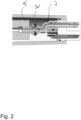
- Figure 1 schematically a tool 1' for a medical treatment according to the state of the art in a cross sectional view is shown.
- Figure 1 illustrates a tool 1' for a dental treatment, in particular a scaler for removing dental calculus.
- a tool 1' uses a vibration movement, in particular an ultrasound vibration movement, for moving a tool tip 2' such that the tool tip 2', located at or next to dental calculus at a tooth, removes said dental calculus from the tooth being treated during operation.
- the tool 1' includes a transducer 10', in particular being intended to cause the ultrasound vibration movement along a vibration direction VD.
- the transducer 10' includes at least one piezo element 12, preferably a stack 12' of piezo elements 12.
- piezo elements 12 are typically configured such that an electrical energy can be translated to a small expansion of the piezo element 12 in vibration direction VD that creates the ultrasound vibration movement of the tool tip 2'.
- the transducer 10' comprises a back mass 13' and a sonotrode 11', the sonotrode 11' being coupled to the tool tip 2'. It is also conceivable that the transducer 10' includes an adapter for mounting the tool tip 2' to the sonotrode 11'.
- the stack 12' of piezo elements 12 is located between the sonotrode 11' and the back mass 13'.
- the transducer 10' is a Langevin transducer, causing a vibration motion having a maximum amplitude at the front sides of the transducer 10', especially at the front sides of the sonotrode 11' and the back mass 13', i. e. the front sides of the sonotrode 11' and back mass 13' facing away from each other.
- a vibration node of the established vibration is established during operating the tool 1'.
- the tool tip 2' is represented by a scaler that interacts with a surface of a tooth, in particular its outside, during operation.
- the tool 1 comprises an irrigation fluid channel 8' for transporting an irrigation fluid to the tool tip 2'.
- the irrigation fluid channel 8 passes through the transducer 10'.
- the irrigation fluid being transported during operation to the tool tip 2', can be used for tip irrigation as well as for temperature limitation, i. e. for cooling the transducer 10'.
- such an irrigation fluid influences the vibration movement of the transducer 10'.
- the irrigation fluid passing through the transducer 10' can establish different states such as laminar, turbulent or a state, in which a cavitation is formed.
- These kinds of states of the flow inside the irrigation fluid channel 8 can influence the vibration motion of the transducer 10'.
- at high amplitudes and high frequency cavities, i. e. bubbles are formed, which can damage the tool 1, because shock waves during bubble apparition have a strong energy locally and can destroy material.
- Regions being prone for cavity formation or generating a flow of the irrigation fluid, which damps the vibration movement of the transducer 10' are for example slanted inner wall sides of the irrigation fluid channel 8' or an interface section, the interface section being used to supply the irrigation fluid channel 8' with the irrigation fluid from a supply line 9'.
- interface section the region is meant, in which the fluid exits the supply line 9' and enters the irrigation fluid channel 8'.
- FIG 2 the interface section between the supply line 9' and the irrigation fluid channel 8 'in a tool 1' according to the state of the art is illustrated.
- the interface section is located at the rear end of the back mass 13' and is realized by a flexible hose 7.
- the rear end or distal end of the transducer 10' is prone for generating a flow inside the transported irrigation fluid, which negatively effects the vibration movement of the transducer, in particular by damping the vibrational movement.
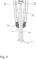
- a tool 1 according to a preferred embodiment of the present invention is shown.
- it is intended to provide a tool 1 that reduces the probability of cavity or bubble formation inside of the irrigation fluid channel 8 and/or reduces the probability for formation of a flow of the irrigation fluid that damps the vibration movement of the transducer 10.
- a channel modifying section 21, 22 is located close to a node of the vibration of the transducer 10.
- Channel modifying sections 21, 22 are those sections, which are prone for strongly influencing the flow characteristics of the irrigation fluid.
- a channel modifying section 21 is formed by an inner side wall of the irrigation fluid channel 8, being slanted relatively to the vibrational direction VD about an angle between 30° and 90° or even 170°.
- Such step-like inner wall sections typically influence the flow of the irrigation fluid, since they transfer their vibrational movement parallel to the vibration direction VD to the fluid.
- Such a channel modifying section 21, 22 however is necessary to reduce the cross section of the irrigation fluid channel 8 and can in general be not avoided.
- a channel modifying section 22 is the interface section between the irrigation fluid channel 8 of the transducer 10 and a supply line 9, which supplies the irrigation fluid channel 8 with the irrigation fluid.
- a ratio between a distance D1, D2 between the channel modifying section 21, 22 and the piezo element 12 measured in a direction parallel to the vibration direction VD to a total length L of the transducer 10, measured in a direction parallel to the vibration direction VD is smaller than 0.15 and more preferably smaller than 0.1. Because of the relative high mass of the back mass 13, the node of the vibration mode is located close to the piezo element 12, preferably the stack 12' of piezo elements 12. As a result, the distance D1, D2 of the channel modifying section 21, 22 being close to the piezo element 12 corresponds to a location of the channel modifying sections 21, 22 being close to the node of the vibration mode of the transducer 10.
- the total length L is given by the extension of the transducer 10 between the front sides of the transducer 10, namely the front sides of the sonotrode 11 and the back mass 13, being opposite to each other along a direction parallel to the vibration direction VD.
- the tool 1 forms an irrigation outlet 14 for ejecting the irrigation fluid at the end of the irrigation fluid channel 8.
- the supply line 9 passes through the back mass 13 of the transducer 10 and is inserted inside a rear/proximal end of the sonotrode 11 in the assembled state.
- the supply line 9 is inserted in a recess, preferably a pot-like recess, at the rear/proximal end of the sonotrode 11.
- the supply line 9 is integrated inside a plug element 20, which can be plugged into the rear end of the transducer 10.
- a sealing element 19 such as an O-ring, is placed at a bottom of the pot-like recess at the rear end of the sonotrode 11.
- the sealing element 19 contacts the distal end section of the plug element 20 at the outside in a sealing matter.
- the transducer 10 and the plug-in element 20 are at least partially integrated inside a housing 30.
- the housing 30 surrounds the part of the transducer 10 including the rear/proximal end of the sonotrode 11, the stack 12' of piezo elements 12 and the back mass 13.
- a filling element 4 and a cap 5 are provided at the distal end of the housing 30 .
- the filling element 4 establishes a sealing at the opening of the housing 30 at its distal end.
- the cap 5 covers both the filing element 4 and the opening of the housing 30 at its distal end.
- the transducer 10 includes a section TF being free of a channel modification outside the section, which extends from the piezo element 12 to the channel modifying section 21, 22.
- the transducer 10 of the tool 1 of the present invention for example includes a step-free and thin irrigation fluid channel 8 having no step-like reduction of the cross section extending perpendicular to the vibration direction VD of the tool 1.
- the cross section of the section TF being free of channel modification has an extension being smaller than 2 mm, preferably smaller than 1 mm and preferably smaller than 0.75 mm.
- the surface, interacting with the fluid is significantly reduced and, therefore, the vibration movement of the transducer 10 does not affect the irrigation fluid flow in such sections of the transducer 10 having a high amplitude of vibration.
- FIG 4 a detailed view of the tool 1 of figure 3 is shown including the channel modifying sections 21, 22 as well as the opening of the housing 30 at its distal end having the filling material 4 and the cap 5.
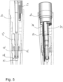
- FIG 5 the proximal end of a handpiece 3 of the tool of figure 3 is shown in a cross section view (top) and in a perspective view (bottom).
- the plug element 20 is connected to a connector element 40 for electrical communication between the tool and an external control device.
- the perspective view shows that the plug element 20 has protrusions 25 which protrude radially from the outside of the plug element 20.
- strut elements forming the protrusions, being arranged at equal distances along a circumferential direction. These strut elements can be used for pushing the transducer 10 into the proper location during assembling the tool 1. Furthermore, it is provided that the strut elements 25 are inserted inside corresponding recesses of the connector element 40 for connecting the plug-in element 20 and the connector 40.
- the tool tip 2 is formed as a non-bent component.
- the tool tip 2 extends along an extending direction in form of a needle, i. e. the tool tip 2 has a straight course along the extension direction from a inserting section at a proximal end, being inserted into a recess in the interface section, to a pointed tip at the distal end of the tool tip 2.
- the tool tip 2 differs from the scaler tips known by the prior art that are typically bent for meeting the requirement that the tool tip 2 is curved forming an angle of around 120° relative to the vibration direction, in particular for meeting the requirements that are defined by an oral cavity geometry.
- the tool tip 2 is connected to the sonotrode 11 in the interface section 1 by a frictional-fitting and/or form-fitting, in particular without a screwing mechanism.
- the tool tip 2 is connected to the interface section of the sonotrode 11 by a press fit connection.
- the tool tip 2 is arranged or connected to the sonotrode permanently or non-permanently, for example.
- the tool tip 2 is inserted in a recess, wherein the recess is included in the sonotrode 11.
- the tool tip 2 extends in an extending direction being slanted relative to the vibration direction VD in the interface section.
- a non-bent, i. e. needle-like, tool tip 2 is the possibility of relying on new or different materials that, for example, are not able to be bent in a way sufficient to realize a bent tool tip 2 in form of a scaler of the prior art.
- the extending direction and the vibration direction VD of the tool 1 having the non-bent tool tip 2 form an angle that mainly corresponds to 120°, for meeting the requirements, being defined by the oral cavity geometry.
Landscapes
- Health & Medical Sciences (AREA)
- Dentistry (AREA)
- Epidemiology (AREA)
- Life Sciences & Earth Sciences (AREA)
- Animal Behavior & Ethology (AREA)
- General Health & Medical Sciences (AREA)
- Public Health (AREA)
- Veterinary Medicine (AREA)
- Oral & Maxillofacial Surgery (AREA)
- Dental Tools And Instruments Or Auxiliary Dental Instruments (AREA)
- Surgical Instruments (AREA)
Claims (12)
- Instrument (1) für eine zahnärztliche Behandlung, nämlich eine Sonde, das einen Wandler (10) mit mindestens einem Piezoelement (12) aufweist, um eine Vibrationsbewegung entlang einer Vibrationsrichtung (VD) in einem vibrierenden Zustand zu verursachen,wobei der Wandler (10), insbesondere eine Sonotrode (11) des Wandlers (10), einen Spülflüssigkeitskanal (8) zum Leiten einer Spülflüssigkeit einschließt, wobei eine Versorgungsleitung (9) durch den Wandler (10) führt und wobei eine Schnittstelle zwischen der Versorgungsleitung (9) und dem Spülflüssigkeitskanal (8) des Wandlers (10) stromabwärts von dem mindestens einen Piezoelement (12) angeordnet ist, wobei die Versorgungsleitung (9) durch eine Massestück (13) des Wandlers führt,wobei das Werkzeug (1) einen kanalverändernden Abschnitt (21, 22) aufweist, der während der Verwendung des Instruments (1) von der Spülflüssigkeit durchströmt wird,wobei der kanalverändernde Abschnitt (21, 22) gebildet wird durch- einen inneren Wandabschnitt des Spülflüssigkeitskanals (8), der relativ zur Vibrationsrichtung (VD) um einen Winkel zwischen 30° und 150° geneigt ist und/oder- eine Schnittstelle zwischen einer Versorgungsleitung (9) und dem Spülflüssigkeitskanal (18) des Wandlers (10),wobei zur Verringerung eines Einflusses einer Vibration des Wandlers auf die Spülflüssigkeit während der Verwendung des Instruments (1) ein Verhältnis von- einem Abstand (D1, D2) zwischen dem kanalverändernden Abschnitt (21, 22) und dem mindestens einen Piezoelement (12), gemessen in einer Richtung parallel zur Vibrationsrichtung (VD) zu- einer Gesamtlänge (L) des Wandlers (10), gemessen in einer Richtung parallel zur Vibrationsrichtung (VD),kleiner als 0,15 und vorzugsweise kleiner als 0,1 ist.
- Instrument (1) nach Anspruch 1, wobei der Spülflüssigkeitskanal (8) einen Abschnitt aufweist, der keine Kanalveränderung (TF) umfasst und sich von dem kanalverändernden Abschnitt (21, 22) zu einem distalen Ende des Spülflüssigkeitskanals (8) erstreckt.
- Instrument (1) nach Anspruch 2, wobei der Spülflüssigkeitskanal (8) einen Querschnitt in einer Ebene senkrecht zur Vibrationsrichtung (VD) aufweist, wobei der Querschnitt des Abschnitts, der keine Kanalveränderung (TF) umfasst, eine Erstreckung aufweist, die kleiner als 2 mm, bevorzugt kleiner als 1 mm und besonders bevorzugt kleiner als 0,75 mm ist.
- Instrument (1) nach Anspruch 2 oder 3, wobei ein Verhältnis zwischen einer Erstreckung der kanalverändernden Abschnitte (21, 22) zu einer Gesamtlänge (L) des Wandlers (10) kleiner als 0,25, bevorzugt kleiner als 0,2 und besonders bevorzugt kleiner als 0,15 ist.
- Instrument (1) nach einem der vorangehenden Ansprüche, wobei am Ende des Spülflüssigkeitskanals (8) ein Spülungsauslass (14) zum Ausstoßen der Spülflüssigkeit entlang einer Ausstoßrichtung angeordnet ist, wobei besonders bevorzugt ein Verhältnis eines Durchmessers des Spülflüssigkeitskanals (8) zu einer Länge des Abschnitts, der frei von Kanalveränderung (TF) ist, einen Wert zwischen 0,01 und 0,04, bevorzugt zwischen 0,02 und 0,03 oder besonders bevorzugt zwischen 0,02 und 0,025 aufweist.
- Instrument (1) nach einem der vorangehenden Ansprüche, wobei die Versorgungsleitung (9) in eine proximale Vorderseite des Wandlers (10), insbesondere in die proximale Vorderseite der Sonotrode (11), eingeführt ist.
- Instrument (1) nach Anspruch 6, wobei ein Dichtungselement (19), wie ein O-Ring,- zwischen dem eingeführten Teil der Versorgungsleitung (9) und dem Wandler (10), insbesondere der Sonotrode (11) und/oder- an einem während der Verwendung auftretenden Vibrationspunkt angeordnet ist.
- Instrument (1) nach einem der vorangehenden Ansprüche, wobei ein die Versorgungsleitung (9) einschließendes Verschlusselement (20) mindestens einen radial verlaufenden Vorsprung (25) aufweist.
- Instrument (1) nach Anspruch 8, wobei am hinteren Ende des Instruments (1) ein Verbindungselement (40) angeordnet ist, wobei vorzugsweise das Verbindungselement (40) mit dem Verschlusselement (20) verbunden ist, insbesondere über den mindestens einen radial erstreckenden Vorsprung (25).
- Instrument (1) nach einem der vorangehenden Ansprüche, wobei ein Freiraum (35) zwischen dem Verschlusselement (20) und dem Massestück (13) in einer Richtung parallel zur Vibrationsrichtung (VD) angeordnet ist.
- Instrument (1) nach einem der vorangehenden Ansprüche, wobei die Werkzeugspitze (2) mit der Sonotrode (11) durch eine Presspassung oder auf dauerhafte Weise verbunden ist.
- Instrument (1) nach einem der vorangehenden Ansprüche, wobei die Werkzeugspitze (2) nicht gebogen ist.
Applications Claiming Priority (3)
| Application Number | Priority Date | Filing Date | Title |
|---|---|---|---|
| EP20154168.7A EP3858285B1 (de) | 2020-01-28 | 2020-01-28 | Werkzeug für eine medizinische behandlung |
| EP20154169.5A EP3858286B1 (de) | 2020-01-28 | 2020-01-28 | Werkzeug für eine medizinische behandlung |
| PCT/EP2021/052038 WO2021152049A1 (en) | 2020-01-28 | 2021-01-28 | Tool for a medical treatment, preferably a dental treatment, and method for operating such a tool |
Publications (3)
| Publication Number | Publication Date |
|---|---|
| EP4096567A1 EP4096567A1 (de) | 2022-12-07 |
| EP4096567C0 EP4096567C0 (de) | 2024-08-21 |
| EP4096567B1 true EP4096567B1 (de) | 2024-08-21 |
Family
ID=74418471
Family Applications (2)
| Application Number | Title | Priority Date | Filing Date |
|---|---|---|---|
| EP21702483.5A Active EP4096566B1 (de) | 2020-01-28 | 2021-01-28 | Instrument für eine zahnärztliche behandlung |
| EP21702484.3A Active EP4096567B1 (de) | 2020-01-28 | 2021-01-28 | Werkzeug für eine medizinische behandlung, vorzugsweise zahnärztliche behandlung, und verfahren zum betrieb eines solchen werkzeugs |
Family Applications Before (1)
| Application Number | Title | Priority Date | Filing Date |
|---|---|---|---|
| EP21702483.5A Active EP4096566B1 (de) | 2020-01-28 | 2021-01-28 | Instrument für eine zahnärztliche behandlung |
Country Status (2)
| Country | Link |
|---|---|
| EP (2) | EP4096566B1 (de) |
| WO (2) | WO2021152049A1 (de) |
Families Citing this family (3)
| Publication number | Priority date | Publication date | Assignee | Title |
|---|---|---|---|---|
| WO2024083763A1 (en) * | 2022-10-21 | 2024-04-25 | Ferton Holding S.A. | A tip holder, a tool tip and a medical tool |
| EP4356872B1 (de) * | 2022-10-21 | 2025-08-06 | Ferton Holding S.A. | Werkzeug zum transfer einer dentalwerkzeugspitze zwischen einem montierten und einem demontierbaren zustand und verfahren zum entfernen einer dentalwerkzeugspitze von einem dentalinstrument |
| WO2026041741A1 (en) | 2024-08-22 | 2026-02-26 | Ferton Holding S.A. | A tool for a dental treatment and a method to quantify a handling of the tool |
Family Cites Families (9)
| Publication number | Priority date | Publication date | Assignee | Title |
|---|---|---|---|---|
| US4370131A (en) * | 1977-06-24 | 1983-01-25 | Surgical Design | Ultrasonic transducer tips |
| US4332558A (en) * | 1980-05-20 | 1982-06-01 | Lustig Leopold P | Dental scaling apparatus |
| FR2584916B1 (fr) * | 1985-07-19 | 1990-05-25 | Satelec Soc | Appareil de curetage ou d'exerese de tissus biologiques par un instrument vibrant a des frequences ultrasonores |
| US6716028B2 (en) * | 2000-08-04 | 2004-04-06 | Hu-Friedy Mfg. Co., Inc. | Ultrasonic swivel insert |
| US20020127512A1 (en) * | 2001-02-22 | 2002-09-12 | Shu Chen | Ultrasonic unit with rear swivel |
| WO2013116655A1 (en) * | 2012-02-03 | 2013-08-08 | Gouery Gwenael D | Cutting tips for ultrasonic surgical system |
| EP3086884B1 (de) * | 2013-12-27 | 2019-12-11 | Inter-Med, Inc. | Piezoelektrische vorrichtung und schaltkreis |
| CN106491229A (zh) * | 2016-11-30 | 2017-03-15 | 桂林市啄木鸟医疗器械有限公司 | 一种新型换能器及含其的手柄 |
| CN107041790A (zh) * | 2017-05-20 | 2017-08-15 | 桂林市啄木鸟医疗器械有限公司 | 一种用于超声洁牙机中手柄内的防转动结构 |
-
2021
- 2021-01-28 EP EP21702483.5A patent/EP4096566B1/de active Active
- 2021-01-28 WO PCT/EP2021/052038 patent/WO2021152049A1/en not_active Ceased
- 2021-01-28 WO PCT/EP2021/052037 patent/WO2021152048A1/en not_active Ceased
- 2021-01-28 EP EP21702484.3A patent/EP4096567B1/de active Active
Also Published As
| Publication number | Publication date |
|---|---|
| WO2021152048A1 (en) | 2021-08-05 |
| WO2021152049A1 (en) | 2021-08-05 |
| EP4096567C0 (de) | 2024-08-21 |
| EP4096566B1 (de) | 2025-04-23 |
| EP4096566A1 (de) | 2022-12-07 |
| EP4096567A1 (de) | 2022-12-07 |
| EP4096566C0 (de) | 2025-04-23 |
Similar Documents
| Publication | Publication Date | Title |
|---|---|---|
| EP4096567B1 (de) | Werkzeug für eine medizinische behandlung, vorzugsweise zahnärztliche behandlung, und verfahren zum betrieb eines solchen werkzeugs | |
| US6086369A (en) | Ultrasonic dental scaler insert | |
| EP2948096B1 (de) | Ultraschallspitzenanordnung | |
| US5531597A (en) | Transducer activated tool tip | |
| EP0139960A1 (de) | Endodontische Einheit | |
| US5190456A (en) | Air-driven dental scaler | |
| US20030036705A1 (en) | Ultrasonic probe device having an impedance mismatch with rapid attachment and detachment means | |
| CA2462499A1 (en) | Ultrasonic probe device having an impedance mismatch with rapid attachment and detachment means | |
| CN113573664A (zh) | 用于超声波牙科治疗设备的梢端元件、这种牙科治疗设备的运动转换部段、具有这种梢端元件的牙科治疗设备以及用于这种梢端元件的梢端卡设备 | |
| JP3703838B2 (ja) | 変換器作動のツール・チップ | |
| CN115038407B (zh) | 用于医学治疗的工具、用于这种工具的工具梢部、移动部分和/或手持件以及用于生产这种用于医学治疗的工具的方法 | |
| EP4096565B1 (de) | Werkzeug für eine medizinische behandlung | |
| US20040234924A1 (en) | Waterguide design and method and tube assembly for use therewith | |
| EP0261272B1 (de) | Luftbetriebener Zahnsteinentferner | |
| EP4356866A1 (de) | Spitzenhalter, werkzeugspitze und medizinisches werkzeug | |
| JP7573839B2 (ja) | ツールチップ、そうしたツールチップを備える歯科治療用のツール、及びそうしたツールの動作方法 | |
| WO2024083763A1 (en) | A tip holder, a tool tip and a medical tool | |
| JP2005052411A (ja) | 超音波吸引装置 | |
| AU2002348422A1 (en) | Ultrasonic probe device with rapid attachment and detachment means having a line contact collet | |
| AU2002363418A1 (en) | Ultrasonic probe device having an impedance mismatch with rapid attachment and detachment means |
Legal Events
| Date | Code | Title | Description |
|---|---|---|---|
| STAA | Information on the status of an ep patent application or granted ep patent |
Free format text: STATUS: UNKNOWN |
|
| STAA | Information on the status of an ep patent application or granted ep patent |
Free format text: STATUS: THE INTERNATIONAL PUBLICATION HAS BEEN MADE |
|
| PUAI | Public reference made under article 153(3) epc to a published international application that has entered the european phase |
Free format text: ORIGINAL CODE: 0009012 |
|
| STAA | Information on the status of an ep patent application or granted ep patent |
Free format text: STATUS: REQUEST FOR EXAMINATION WAS MADE |
|
| 17P | Request for examination filed |
Effective date: 20220719 |
|
| AK | Designated contracting states |
Kind code of ref document: A1 Designated state(s): AL AT BE BG CH CY CZ DE DK EE ES FI FR GB GR HR HU IE IS IT LI LT LU LV MC MK MT NL NO PL PT RO RS SE SI SK SM TR |
|
| DAV | Request for validation of the european patent (deleted) | ||
| DAX | Request for extension of the european patent (deleted) | ||
| STAA | Information on the status of an ep patent application or granted ep patent |
Free format text: STATUS: EXAMINATION IS IN PROGRESS |
|
| 17Q | First examination report despatched |
Effective date: 20230823 |
|
| GRAP | Despatch of communication of intention to grant a patent |
Free format text: ORIGINAL CODE: EPIDOSNIGR1 |
|
| STAA | Information on the status of an ep patent application or granted ep patent |
Free format text: STATUS: GRANT OF PATENT IS INTENDED |
|
| INTG | Intention to grant announced |
Effective date: 20240321 |
|
| GRAS | Grant fee paid |
Free format text: ORIGINAL CODE: EPIDOSNIGR3 |
|
| GRAA | (expected) grant |
Free format text: ORIGINAL CODE: 0009210 |
|
| STAA | Information on the status of an ep patent application or granted ep patent |
Free format text: STATUS: THE PATENT HAS BEEN GRANTED |
|
| AK | Designated contracting states |
Kind code of ref document: B1 Designated state(s): AL AT BE BG CH CY CZ DE DK EE ES FI FR GB GR HR HU IE IS IT LI LT LU LV MC MK MT NL NO PL PT RO RS SE SI SK SM TR |
|
| REG | Reference to a national code |
Ref country code: GB Ref legal event code: FG4D |
|
| REG | Reference to a national code |
Ref country code: CH Ref legal event code: EP |
|
| REG | Reference to a national code |
Ref country code: IE Ref legal event code: FG4D |
|
| REG | Reference to a national code |
Ref country code: DE Ref legal event code: R096 Ref document number: 602021017493 Country of ref document: DE |
|
| U01 | Request for unitary effect filed |
Effective date: 20240920 |
|
| U07 | Unitary effect registered |
Designated state(s): AT BE BG DE DK EE FI FR IT LT LU LV MT NL PT RO SE SI Effective date: 20241015 |
|
| PG25 | Lapsed in a contracting state [announced via postgrant information from national office to epo] |
Ref country code: NO Free format text: LAPSE BECAUSE OF FAILURE TO SUBMIT A TRANSLATION OF THE DESCRIPTION OR TO PAY THE FEE WITHIN THE PRESCRIBED TIME-LIMIT Effective date: 20241121 |
|
| PG25 | Lapsed in a contracting state [announced via postgrant information from national office to epo] |
Ref country code: GR Free format text: LAPSE BECAUSE OF FAILURE TO SUBMIT A TRANSLATION OF THE DESCRIPTION OR TO PAY THE FEE WITHIN THE PRESCRIBED TIME-LIMIT Effective date: 20241122 Ref country code: PL Free format text: LAPSE BECAUSE OF FAILURE TO SUBMIT A TRANSLATION OF THE DESCRIPTION OR TO PAY THE FEE WITHIN THE PRESCRIBED TIME-LIMIT Effective date: 20240821 |
|
| PG25 | Lapsed in a contracting state [announced via postgrant information from national office to epo] |
Ref country code: IS Free format text: LAPSE BECAUSE OF FAILURE TO SUBMIT A TRANSLATION OF THE DESCRIPTION OR TO PAY THE FEE WITHIN THE PRESCRIBED TIME-LIMIT Effective date: 20241221 |
|
| PG25 | Lapsed in a contracting state [announced via postgrant information from national office to epo] |
Ref country code: HR Free format text: LAPSE BECAUSE OF FAILURE TO SUBMIT A TRANSLATION OF THE DESCRIPTION OR TO PAY THE FEE WITHIN THE PRESCRIBED TIME-LIMIT Effective date: 20240821 |
|
| PG25 | Lapsed in a contracting state [announced via postgrant information from national office to epo] |
Ref country code: ES Free format text: LAPSE BECAUSE OF FAILURE TO SUBMIT A TRANSLATION OF THE DESCRIPTION OR TO PAY THE FEE WITHIN THE PRESCRIBED TIME-LIMIT Effective date: 20240821 Ref country code: RS Free format text: LAPSE BECAUSE OF FAILURE TO SUBMIT A TRANSLATION OF THE DESCRIPTION OR TO PAY THE FEE WITHIN THE PRESCRIBED TIME-LIMIT Effective date: 20241121 |
|
| PG25 | Lapsed in a contracting state [announced via postgrant information from national office to epo] |
Ref country code: RS Free format text: LAPSE BECAUSE OF FAILURE TO SUBMIT A TRANSLATION OF THE DESCRIPTION OR TO PAY THE FEE WITHIN THE PRESCRIBED TIME-LIMIT Effective date: 20241121 Ref country code: PL Free format text: LAPSE BECAUSE OF FAILURE TO SUBMIT A TRANSLATION OF THE DESCRIPTION OR TO PAY THE FEE WITHIN THE PRESCRIBED TIME-LIMIT Effective date: 20240821 Ref country code: NO Free format text: LAPSE BECAUSE OF FAILURE TO SUBMIT A TRANSLATION OF THE DESCRIPTION OR TO PAY THE FEE WITHIN THE PRESCRIBED TIME-LIMIT Effective date: 20241121 Ref country code: IS Free format text: LAPSE BECAUSE OF FAILURE TO SUBMIT A TRANSLATION OF THE DESCRIPTION OR TO PAY THE FEE WITHIN THE PRESCRIBED TIME-LIMIT Effective date: 20241221 Ref country code: HR Free format text: LAPSE BECAUSE OF FAILURE TO SUBMIT A TRANSLATION OF THE DESCRIPTION OR TO PAY THE FEE WITHIN THE PRESCRIBED TIME-LIMIT Effective date: 20240821 Ref country code: GR Free format text: LAPSE BECAUSE OF FAILURE TO SUBMIT A TRANSLATION OF THE DESCRIPTION OR TO PAY THE FEE WITHIN THE PRESCRIBED TIME-LIMIT Effective date: 20241122 Ref country code: ES Free format text: LAPSE BECAUSE OF FAILURE TO SUBMIT A TRANSLATION OF THE DESCRIPTION OR TO PAY THE FEE WITHIN THE PRESCRIBED TIME-LIMIT Effective date: 20240821 |
|
| U20 | Renewal fee for the european patent with unitary effect paid |
Year of fee payment: 5 Effective date: 20250127 |
|
| PG25 | Lapsed in a contracting state [announced via postgrant information from national office to epo] |
Ref country code: SM Free format text: LAPSE BECAUSE OF FAILURE TO SUBMIT A TRANSLATION OF THE DESCRIPTION OR TO PAY THE FEE WITHIN THE PRESCRIBED TIME-LIMIT Effective date: 20240821 |
|
| PGFP | Annual fee paid to national office [announced via postgrant information from national office to epo] |
Ref country code: CH Payment date: 20250201 Year of fee payment: 5 |
|
| PG25 | Lapsed in a contracting state [announced via postgrant information from national office to epo] |
Ref country code: CZ Free format text: LAPSE BECAUSE OF FAILURE TO SUBMIT A TRANSLATION OF THE DESCRIPTION OR TO PAY THE FEE WITHIN THE PRESCRIBED TIME-LIMIT Effective date: 20240821 |
|
| PG25 | Lapsed in a contracting state [announced via postgrant information from national office to epo] |
Ref country code: SK Free format text: LAPSE BECAUSE OF FAILURE TO SUBMIT A TRANSLATION OF THE DESCRIPTION OR TO PAY THE FEE WITHIN THE PRESCRIBED TIME-LIMIT Effective date: 20240821 |
|
| PGFP | Annual fee paid to national office [announced via postgrant information from national office to epo] |
Ref country code: GB Payment date: 20250123 Year of fee payment: 5 |
|
| PLBE | No opposition filed within time limit |
Free format text: ORIGINAL CODE: 0009261 |
|
| STAA | Information on the status of an ep patent application or granted ep patent |
Free format text: STATUS: NO OPPOSITION FILED WITHIN TIME LIMIT |
|
| 26N | No opposition filed |
Effective date: 20250522 |
|
| PG25 | Lapsed in a contracting state [announced via postgrant information from national office to epo] |
Ref country code: MC Free format text: LAPSE BECAUSE OF FAILURE TO SUBMIT A TRANSLATION OF THE DESCRIPTION OR TO PAY THE FEE WITHIN THE PRESCRIBED TIME-LIMIT Effective date: 20240821 |
|
| PG25 | Lapsed in a contracting state [announced via postgrant information from national office to epo] |
Ref country code: IE Free format text: LAPSE BECAUSE OF NON-PAYMENT OF DUE FEES Effective date: 20250128 |
|
| REG | Reference to a national code |
Ref country code: CH Ref legal event code: U11 Free format text: ST27 STATUS EVENT CODE: U-0-0-U10-U11 (AS PROVIDED BY THE NATIONAL OFFICE) Effective date: 20260201 |
|
| U20 | Renewal fee for the european patent with unitary effect paid |
Year of fee payment: 6 Effective date: 20260128 |