EP4096011A2 - Barre omnibus permettant de mettre en contact des éléments de batterie retenues dans un porte-élément, agencement de module de batterie et procédé de connexion d'une barre omnibus à un élément de batterie - Google Patents
Barre omnibus permettant de mettre en contact des éléments de batterie retenues dans un porte-élément, agencement de module de batterie et procédé de connexion d'une barre omnibus à un élément de batterie Download PDFInfo
- Publication number
- EP4096011A2 EP4096011A2 EP22171473.6A EP22171473A EP4096011A2 EP 4096011 A2 EP4096011 A2 EP 4096011A2 EP 22171473 A EP22171473 A EP 22171473A EP 4096011 A2 EP4096011 A2 EP 4096011A2
- Authority
- EP
- European Patent Office
- Prior art keywords
- connection
- contact
- contacting
- cell
- battery
- Prior art date
- Legal status (The legal status is an assumption and is not a legal conclusion. Google has not performed a legal analysis and makes no representation as to the accuracy of the status listed.)
- Pending
Links
Images


Classifications
-
- H—ELECTRICITY
- H01—ELECTRIC ELEMENTS
- H01M—PROCESSES OR MEANS, e.g. BATTERIES, FOR THE DIRECT CONVERSION OF CHEMICAL ENERGY INTO ELECTRICAL ENERGY
- H01M50/00—Constructional details or processes of manufacture of the non-active parts of electrochemical cells other than fuel cells, e.g. hybrid cells
- H01M50/50—Current conducting connections for cells or batteries
- H01M50/502—Interconnectors for connecting terminals of adjacent batteries; Interconnectors for connecting cells outside a battery casing
- H01M50/507—Interconnectors for connecting terminals of adjacent batteries; Interconnectors for connecting cells outside a battery casing comprising an arrangement of two or more busbars within a container structure, e.g. busbar modules
-
- H—ELECTRICITY
- H01—ELECTRIC ELEMENTS
- H01M—PROCESSES OR MEANS, e.g. BATTERIES, FOR THE DIRECT CONVERSION OF CHEMICAL ENERGY INTO ELECTRICAL ENERGY
- H01M50/00—Constructional details or processes of manufacture of the non-active parts of electrochemical cells other than fuel cells, e.g. hybrid cells
- H01M50/50—Current conducting connections for cells or batteries
- H01M50/528—Fixed electrical connections, i.e. not intended for disconnection
-
- H—ELECTRICITY
- H01—ELECTRIC ELEMENTS
- H01M—PROCESSES OR MEANS, e.g. BATTERIES, FOR THE DIRECT CONVERSION OF CHEMICAL ENERGY INTO ELECTRICAL ENERGY
- H01M50/00—Constructional details or processes of manufacture of the non-active parts of electrochemical cells other than fuel cells, e.g. hybrid cells
- H01M50/20—Mountings; Secondary casings or frames; Racks, modules or packs; Suspension devices; Shock absorbers; Transport or carrying devices; Holders
- H01M50/204—Racks, modules or packs for multiple batteries or multiple cells
- H01M50/207—Racks, modules or packs for multiple batteries or multiple cells characterised by their shape
- H01M50/213—Racks, modules or packs for multiple batteries or multiple cells characterised by their shape adapted for cells having curved cross-section, e.g. round or elliptic
-
- H—ELECTRICITY
- H01—ELECTRIC ELEMENTS
- H01M—PROCESSES OR MEANS, e.g. BATTERIES, FOR THE DIRECT CONVERSION OF CHEMICAL ENERGY INTO ELECTRICAL ENERGY
- H01M50/00—Constructional details or processes of manufacture of the non-active parts of electrochemical cells other than fuel cells, e.g. hybrid cells
- H01M50/20—Mountings; Secondary casings or frames; Racks, modules or packs; Suspension devices; Shock absorbers; Transport or carrying devices; Holders
- H01M50/249—Mountings; Secondary casings or frames; Racks, modules or packs; Suspension devices; Shock absorbers; Transport or carrying devices; Holders specially adapted for aircraft or vehicles, e.g. cars or trains
-
- H—ELECTRICITY
- H01—ELECTRIC ELEMENTS
- H01M—PROCESSES OR MEANS, e.g. BATTERIES, FOR THE DIRECT CONVERSION OF CHEMICAL ENERGY INTO ELECTRICAL ENERGY
- H01M50/00—Constructional details or processes of manufacture of the non-active parts of electrochemical cells other than fuel cells, e.g. hybrid cells
- H01M50/50—Current conducting connections for cells or batteries
- H01M50/502—Interconnectors for connecting terminals of adjacent batteries; Interconnectors for connecting cells outside a battery casing
- H01M50/503—Interconnectors for connecting terminals of adjacent batteries; Interconnectors for connecting cells outside a battery casing characterised by the shape of the interconnectors
-
- H—ELECTRICITY
- H01—ELECTRIC ELEMENTS
- H01M—PROCESSES OR MEANS, e.g. BATTERIES, FOR THE DIRECT CONVERSION OF CHEMICAL ENERGY INTO ELECTRICAL ENERGY
- H01M50/00—Constructional details or processes of manufacture of the non-active parts of electrochemical cells other than fuel cells, e.g. hybrid cells
- H01M50/50—Current conducting connections for cells or batteries
- H01M50/502—Interconnectors for connecting terminals of adjacent batteries; Interconnectors for connecting cells outside a battery casing
- H01M50/505—Interconnectors for connecting terminals of adjacent batteries; Interconnectors for connecting cells outside a battery casing comprising a single busbar
-
- H—ELECTRICITY
- H01—ELECTRIC ELEMENTS
- H01M—PROCESSES OR MEANS, e.g. BATTERIES, FOR THE DIRECT CONVERSION OF CHEMICAL ENERGY INTO ELECTRICAL ENERGY
- H01M50/00—Constructional details or processes of manufacture of the non-active parts of electrochemical cells other than fuel cells, e.g. hybrid cells
- H01M50/50—Current conducting connections for cells or batteries
- H01M50/502—Interconnectors for connecting terminals of adjacent batteries; Interconnectors for connecting cells outside a battery casing
- H01M50/514—Methods for interconnecting adjacent batteries or cells
- H01M50/516—Methods for interconnecting adjacent batteries or cells by welding, soldering or brazing
-
- H—ELECTRICITY
- H01—ELECTRIC ELEMENTS
- H01M—PROCESSES OR MEANS, e.g. BATTERIES, FOR THE DIRECT CONVERSION OF CHEMICAL ENERGY INTO ELECTRICAL ENERGY
- H01M50/00—Constructional details or processes of manufacture of the non-active parts of electrochemical cells other than fuel cells, e.g. hybrid cells
- H01M50/50—Current conducting connections for cells or batteries
- H01M50/502—Interconnectors for connecting terminals of adjacent batteries; Interconnectors for connecting cells outside a battery casing
- H01M50/521—Interconnectors for connecting terminals of adjacent batteries; Interconnectors for connecting cells outside a battery casing characterised by the material
- H01M50/522—Inorganic material
-
- H—ELECTRICITY
- H01—ELECTRIC ELEMENTS
- H01R—ELECTRICALLY-CONDUCTIVE CONNECTIONS; STRUCTURAL ASSOCIATIONS OF A PLURALITY OF MUTUALLY-INSULATED ELECTRICAL CONNECTING ELEMENTS; COUPLING DEVICES; CURRENT COLLECTORS
- H01R43/00—Apparatus or processes specially adapted for manufacturing, assembling, maintaining, or repairing of line connectors or current collectors or for joining electric conductors
- H01R43/02—Apparatus or processes specially adapted for manufacturing, assembling, maintaining, or repairing of line connectors or current collectors or for joining electric conductors for soldered or welded connections
- H01R43/0263—Apparatus or processes specially adapted for manufacturing, assembling, maintaining, or repairing of line connectors or current collectors or for joining electric conductors for soldered or welded connections for positioning or holding parts during soldering or welding process
-
- H—ELECTRICITY
- H02—GENERATION; CONVERSION OR DISTRIBUTION OF ELECTRIC POWER
- H02G—INSTALLATION OF ELECTRIC CABLES OR LINES, OR OF COMBINED OPTICAL AND ELECTRIC CABLES OR LINES
- H02G5/00—Installations of bus-bars
-
- H—ELECTRICITY
- H01—ELECTRIC ELEMENTS
- H01M—PROCESSES OR MEANS, e.g. BATTERIES, FOR THE DIRECT CONVERSION OF CHEMICAL ENERGY INTO ELECTRICAL ENERGY
- H01M2220/00—Batteries for particular applications
- H01M2220/20—Batteries in motive systems, e.g. vehicle, ship, plane
-
- Y—GENERAL TAGGING OF NEW TECHNOLOGICAL DEVELOPMENTS; GENERAL TAGGING OF CROSS-SECTIONAL TECHNOLOGIES SPANNING OVER SEVERAL SECTIONS OF THE IPC; TECHNICAL SUBJECTS COVERED BY FORMER USPC CROSS-REFERENCE ART COLLECTIONS [XRACs] AND DIGESTS
- Y02—TECHNOLOGIES OR APPLICATIONS FOR MITIGATION OR ADAPTATION AGAINST CLIMATE CHANGE
- Y02E—REDUCTION OF GREENHOUSE GAS [GHG] EMISSIONS, RELATED TO ENERGY GENERATION, TRANSMISSION OR DISTRIBUTION
- Y02E60/00—Enabling technologies; Technologies with a potential or indirect contribution to GHG emissions mitigation
- Y02E60/10—Energy storage using batteries
Definitions
- the present invention relates to an improved busbar for contacting held in a cell holder, for example cylindrical, battery cells to form a battery module of a high-voltage battery, such as a traction battery for a vehicle, and a corresponding battery module arrangement for forming a high-voltage battery, such as a traction battery for a vehicle, and a method for connecting a bus bar to a cell contact of a battery cell in a battery module assembly.
- a high-voltage battery such as a traction battery for a vehicle
- a corresponding battery module arrangement for forming a high-voltage battery, such as a traction battery for a vehicle
- High-voltage batteries are known from the prior art, the battery cells of which are connected to busbars, also known as current collectors or busbars. Batteries are also referred to as accumulators. These are usually electrochemical accumulators, in particular lithium-ion accumulators. Batteries of this type are usually not constructed as a monoblock, but in a modular manner from a large number of battery cells which are mechanically and electrically connected to one another. For the construction of a battery system in an electric vehicle, it is correspondingly known to arrange battery cells in battery modules and to assemble these to form a battery. This increases the configurability of batteries and enables the use of comparatively inexpensive standard battery cells when constructing batteries. The battery cells of a battery module can be held by a cell holder.
- This is a body extending in a plane of extension, which is usually made of a non-conductive material such as plastic, and which usually comprises a large number of receptacles arranged in a predetermined pattern in relation to the plane of extension for accommodating a battery cell.
- a battery cell is understood to be an electrochemical storage cell, preferably a secondary cell.
- the term "cell” can be understood as the smallest contactable structural unit.
- a battery module is understood to be a structural unit that combines a large number of battery cells.
- a battery is accordingly understood to mean a structural unit that is made up of one or more interconnected battery modules.
- Such batteries can include a housing accommodating the battery modules, electrical interconnections and a battery management system. A number of batteries can be interconnected to form a battery system, for example in order to provide an increased capacity of the battery system.
- the battery or the battery system is preferably intended for use in an electric vehicle, but can also be used in other vehicles or other areas of application.
- busbars are welded directly to battery cells, busbars are preformed accordingly so that the sections of the busbar intended for connection to the cells touch the cells in order to be able to be welded to them.
- Preforming is an additional manufacturing step. After a two-dimensional busbar preform has been punched out or cut free from sheet metal, this preform has to be brought into a three-dimensional shape in a further deformation step, for example a deep-drawing or bending step.
- contacting connections in the form of branches that extend three-dimensionally from an elongated main body of the busbar are usually welded directly to the cell contact to be contacted of the respective battery cell using ultrasonic or laser welding.
- these branches extend perpendicularly to the main extension direction of the base body of the busbar, which usually corresponds to a main load direction or a main load path and in which a plurality of battery cells arranged one behind the other are connected in parallel via the busbar.
- the branches for contacting the positive pole of the battery cells extend at a 90° angle from the base body radially to the center of the end face of the cylindrical battery cell having the positive pole there.
- To contact the negative pole they usually run at a 90° angle from the base body tangential to the beaded edge of the end face of the cylindrical battery cell having the negative pole there.
- a battery module arrangement with a conventional busbar with perpendicularly extending from a base contact connections can, for example WO 2021 182 779 A1 , the EP 3 800 702 A1 or the EP 3 790 075 A1 be removed.
- the material utilization in the production of such busbars as a stamped part or a free-cut part is low in the case of branching off contact connections at a 90° angle.
- a hexagonal arrangement of the battery cells also called cell packing, which offers the best use of space, for example with cylindrical battery cells, the electrical connection path between serially connected battery cells is comparatively large, so that the resistance between them is also unnecessarily large.
- a cylindrical battery cell has a pole on its end face in the area of its beaded edge, the electrical contacting of this beaded edge via a contact connection extending perpendicularly from the base body allows only extremely small positional tolerances of the battery cell in relation to the main direction of extension, i.e. in the direction of a row of battery cells connected in parallel.
- an object of the present invention to provide an improved busbar for contacting preferably cylindrical battery cells held in a cell holder to form a battery module of a high-voltage battery, preferably a traction battery for a vehicle, and a corresponding battery module arrangement for forming a high-voltage battery, preferably a traction battery for a vehicle and a method for connecting a busbar to a cell contact of a battery cell.
- a busbar for contacting preferably cylindrical battery cells held in a cell holder to form a battery module of a high-voltage battery, preferably a traction battery for a vehicle, with the features of claim 1.
- a busbar for contacting preferably cylindrical battery cells held in a cell holder to form a battery module of a high-voltage battery, preferably a traction battery for a vehicle, comprising a main body extending in a main extension direction and at least one contacting connection formed in one piece with the main body for contacting a cell contact of one of the battery cells.
- the busbar is designed in such a way that the contacting connection extends in a connection extension direction, which encloses a connection angle of between 0° and less than 90° with the main extension direction, with the busbar preferably having a plurality of the aforementioned contacting connections.
- connection angle is understood to mean the angle that is enclosed by the projection of the connection extension direction and the projection of the main extension direction onto a plane in which the base body extends.
- the plane is defined by the two-dimensional extension of the sheet metal/base body, ie perpendicular to the thickness direction of the sheet metal/base body.
- the contacting connection extends in a connection extension direction, which encloses a connection angle of between 0° and less than 90° with the main extension direction, a particularly high material utilization can be achieved in the production of the busbar, in particular if this is a stamped part or free-cut part made of a ( sheet metal is punched or cut. This is because the contacting connections are spatially close to the base body, in contrast to conventional busbars described in the prior art with contacting connections extending perpendicularly to the main direction of extension.
- the electrical connection path between two battery cells connected in series by the busbar can be kept particularly short, even as short as possible, and accordingly the electrical resistance can therefore be particularly small, even be kept as low as possible.
- the design of the busbar in this way allows the covering of the upper side of the battery cells by the cell holder and busbar to be minimized, so that a particularly effective, even a venting or "venting" of the battery cell(s) that is essentially not prevented by the busbar is made possible in the event of a fault.
- the contacting connection is provided for contacting a cell contact arranged in the area of the circumference of an end face of a cylindrical battery cell, i.e. on its flanged edge, which can be designed, for example, as the negative pole of the battery cell, a high positional tolerance with regard to the position of the busbar and so that the contacting connection on the one hand and the battery cell on the other hand can be achieved in the main extension direction.
- the main direction of extension is arranged in the direction of a parallel connection of battery cells, this enables correspondingly larger positional tolerances of the battery cells connected in parallel in the main direction of extension, and thus, for example, varying distances between the battery cells in the main direction of extension due to manufacturing tolerances of the cell holder.
- the busbar according to the invention therefore allows simpler and more robust (series) production, a simpler design and less material use with regard to the busbar itself and in particular the cell holder and the battery module arrangement.
- connection extension direction is preferably oriented in such a way or the contacting connection extending in the connection extension direction extends in such a way that the cell contact to be contacted by this contacting connection is contacted tangentially to a central axis of the battery cell having the cell contact. So a comparatively large possible position tolerance with respect to the busbar compared to the contacting battery cells and between the battery cells are provided relative to each other.
- the main extension direction is preferably oriented in the main load direction, ie in the direction of a parallel connection of a plurality of battery cells.
- the base body In its main extension direction, the base body has a length that is many times greater than its width transversely to the main extension direction.
- the basic body can be designed as a strip or web. This results in the elongated "rail shape" of the busbar.
- the attachment angle ⁇ is less than 45°, preferably less than 40°, particularly preferably less than 35°, particularly preferably less than 30°, the attachment angle preferably being 25°, 20°, 15°, 10°, 5° or is 0°.
- the smaller the connection angle the greater the available positional tolerances in the main direction of extension.
- the potential degree of material utilization increases with decreasing connection angle, for example if the conductor rail is sheared/cut from sheet metal.
- the length of a current path provided between two series-connected battery cells via the busbar can be made all the smaller, the smaller the connection angle.
- connection angle increases, the distance between two rows of battery cells can be greater transversely to the main extension direction and/or the width of the base body can be made smaller, so that material can be saved with regard to the busbar itself.
- angle of attack range of 0° to 45°, in particular at 0° and 25°.
- the contacting connection extends laterally from the base body in the form of a tab in the connection extension direction in relation to the main extension direction.
- the at least one contact connection is provided laterally on the base body in relation to the main direction of extent.
- the busbar comprises at least one first contact connection for contacting a cell contact of a first polarity of a first battery cell and at least one second contact connection for contacting a Cell contact of the second polarity of a second battery cell.
- the busbar preferably includes a plurality of first and/or second contacting connections.
- the at least one first contact connection is arranged on a first side of the base body and the at least one second contact connection is arranged on a second side of the base body.
- the first contact connection is designed to contact a cell contact of the first polarity arranged centrally on one end face of a battery cell and/or if the second contact connection is designed to contact a second cell contact arranged on the end face of another battery cell in the peripheral region contact polarity.
- the first contacting connection extends from the base body in a first direction relative to the main extension direction and the second contacting connection extends from the base body in a second direction opposite the first direction relative to the main extension direction.
- directional sense related to the main direction of extent here means that this sense of direction comprises at least one component that runs in the direction of the main extent.
- the sense of direction corresponds to a vector, starting at the base or foot or root section of the contact connection on the base body and extending in the direction of the free end of this contact connection.
- the sense of direction can be determined as the component of the attachment direction of extension, which is parallel to the main direction of extension.
- a particularly short current path can be achieved between two series-connected battery cells.
- the first contacting connection extends in a first direction from the base body and the second contacting connection in a second direction, oriented opposite to the first direction, from the base body.
- the base body can be designed with a comparatively small width and thus the material requirements for the busbar can be comparatively small.
- a root section of the first contacting connection, from which the first contacting connection extends from the base body, and a root section of the second contacting connection, from which the second contacting connection extends from the base body are essentially the same in relation to the main direction of extent arranged at height.
- a particularly short current path can thus be achieved between two battery cells connected in series by means of the busbar.
- “Essentially at the same height” is defined as lying within specified tolerances, within which the offset of the root sections, more precisely from the center, in the main extension direction is less than or equal to the width of the tabs transverse to their connection extension direction.
- the base body and the contact connections are designed as a one-piece, ie integral, two-dimensional sheet metal part.
- the busbar is preferably a two-dimensional sheet metal part.
- the at least one contacting connection has a contacting section for contacting a cell contact and in each case a deforming section, via which, when the contacting section is pressed down in a thickness direction of the base body from the height level of the base body to a different height level of the cell contact to be contacted, for contacting of the cell contact, a deformation, preferably an elastic and/or plastic deformation, preferably comprising a bend, can be accommodated.
- the busbar can be designed as a two-dimensional sheet metal part, in which case the at least one contact connection can be deformed in order to physically touch the cell contact to be contacted and the contact can be made in one work step in order to form a permanent, electrically conductive connection between the contact connection and the cell contact.
- the base body comprises an S-shaped transition section between two connection areas, from which at least one contacting connection extends, with each connection area preferably having one have a predetermined width transverse to the direction of main extension and the transition section has a width transverse to which is smaller than the width of the connection areas, wherein the transition section preferably has a length in the direction of main extension that is greater than the length of two contacting connections in the direction of main extension.
- the conductor rail can thus be designed to be particularly material-saving.
- the main body of material includes recessed areas in which a contacting connection can extend in its respective connection angle, preferably 0° for contacting a cell contact in the peripheral area or 25° for contacting a centrally arranged cell contact, without the overall width of the conductor rail to increase significantly.
- a connection area preferably comprises a first and a second contact connection.
- a battery module arrangement for forming a high-voltage battery, preferably a traction battery for a vehicle, with the features of claim 10.
- a battery module arrangement for forming a high-voltage battery preferably a traction battery for a vehicle, comprising a cell holder, a multiplicity of battery cells held in the cell holder and a busbar according to one of the above embodiments.
- busbar can be achieved in an analogous manner by the battery module arrangement, which is why they are not described again here in order to avoid redundancies.
- a method for connecting a busbar to a cell contact of a battery cell comprising bringing together a cell holder for holding battery cells in a battery module with a busbar according to one of the above Embodiments, holding down the busbar with at least one hold-down device, pressing on a contacting connection of the busbar to contact a battery cell held in the cell holder, and welding the contacting connection to the battery cell.
- the method makes it possible, preferably in conjunction with a correspondingly designed support geometry on the cell holder, to bend down the contact connection(s) to the contact surface of the cell contact to be contacted in the same process step with the electrical contact, preferably by laser or ultrasonic welding.
- the busbar By manufacturing the busbar as a purely two-dimensional stamped part or free-cut part, instead of a three-dimensional stamped and bent part, as is the case with conventional methods, the manufacture, handling and, above all, the placement of the busbar on the cell holder and the tolerances to be observed in this regard without inadvertently making electrical contact with the cells before the actual welding process.
- a contacting section of the contacting connection is pressed from a plane defined by the base body of the busbar onto the cell contact of the battery cell to be contacted, with a deformation section of the contacting connection preferably undergoing elastic and/or plastic deformation.
- the contacting connection is pressed onto a battery cell by means of a welding head, which is also used for the immediately following welding of the contacting connection and cell contact.
- both the pressing down or pressing preferably with deformation of the contact connection, preferably its deformation section, from the plane defined by the base body, onto the cell contact of the battery cell to be contacted in one step with the welding of the contact connection and cell contact by a single specially designed tool.
- the welding head is therefore designed to be pressed on the contact connection to and for welding the contact connection to the cell contact.
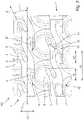
- FIG 1 1 is a schematic plan view of a battery module assembly 100 for forming a high-voltage traction battery of a vehicle. It includes a cell holder, not shown here for reasons of clarity (see Figures 3 to 5 , reference number 2 there), which has a multiplicity of receptacles, in each of which a cylindrical battery cell 3 is accommodated.
- the receptacles of the cell holder 2 are arranged in such a way that the battery cells 3 are arranged perpendicularly to the (longitudinal) central axes 9 in a hexagonal pattern. They therefore represent a hexagonal cell packing.
- the battery module arrangement 100 also includes a plurality of busbars 1 running parallel, which are designed to contact a plurality of the battery cells 3 held in the cell holder 2.
- the busbar 1 comprises a base body 4 extending in a main direction of extension 7 and a plurality of contacting connections 5, 5′ formed in one piece with the base body 4 for contacting one cell contact 6, 6′ of one battery cell 3.
- the main extension direction 7 corresponds to a direction in which battery cells are arranged one behind the other in a row. These are connected in parallel by the conductor rail 1, as explained in more detail below.
- the contact connections 5, 5' are divided into a plurality of first contact connections 5 for contacting a cell contact 6 of a first polarity in each case of a battery cell 3, here the one on in the plan view figure 1 visible end face of the respective battery cell 3 centrally arranged positive pole cell contact 6, and in a plurality of second contact connections 5 'for contacting a cell contact 6' of the second polarity of a battery cell 3, here the arranged on the end face of the respective battery cell 3 in the peripheral area negative pole cell contact 6'.
- first contacting connections 5 are arranged on a first side 10 of the base body 4 laterally on the base body 4 and the second contacting connections 5' are arranged on the other (second) side 11 of the base body 4 laterally on the base body 4.
- the direction of main extent 7 corresponds to the main load direction, i.e. the direction of a parallel connection of a plurality of battery cells 3 each whose positive pole cell contact 6 is electrically connected in parallel, and on the second side 11 through the second contacting connections 5 ′, a further plurality of battery cells 3 arranged in the main extension direction 7 are electrically connected in parallel by contacting their negative pole cell contact 6 ′.
- two battery cells 3 are electrically connected in series in each case by a first contact connection 5 and a second contact connection 5', as in relation to FIG figure 2 explained in more detail.
- connection connections 5, 5' each extend in a connection extension direction 8, 8', which encloses a connection angle ⁇ between 0° and less than 90° with the main extension direction 7.
- the first contact connections 5 have a connection extension direction 8 which is oriented at an attachment angle ⁇ of 25° relative to the main extension direction 7 .
- the second contact connections have a connection extension direction 8′, which is oriented parallel to the main extension direction 7, thus with a connection angle of 0°.
- connection angles ⁇ of the first and second contacting connections 5, 5' are therefore different. Alternatively, they can also have the same attachment angle ⁇ .
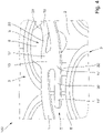
- Figure 12 is a schematic detail view of the plan view figure 1 shown.
- the first contact connections 5 or their connection extension direction 8 extend in a first direction from the base body 4 in relation to the main extension direction 7.
- the second contact connections 5' also extend in relation to the main extension direction 7 or their connection extension directions 8' in a second direction oriented opposite to the first direction of the base body 4.
- each busbar 1 can be considered to be essentially divided into two alternating areas or sections in the main extension direction 7 , namely a connection area 13 and a transition section 14 .
- An S-shaped transition section 14 is arranged between each of two connection areas 13, from which a first contact connection 5 and a second contact connection 5' extend.
- the connection areas 13 have a predetermined width transverse to the main extension direction 7 (ie in the transverse direction 12).
- the transition sections 14 also have a width transverse to the main extension direction 7 that is smaller than the width of the connection areas 13.
- a length 16 of the transition sections 14 in the main extension direction 7 is greater than the sum of the length 15 of the first Contacting connection 5 and the length 15' of the second contacting connection 5' in the main direction of extension 7.
- the busbar 1 or its base body 4 has material-free receiving areas in which a contacting connection 5, 5' can extend.
- the contacting sections 5, 5' are designed in the form of a tab. They extend, starting from a root section 17, 17', with which they are connected in one piece to the base body 4, in the direction of their connection extension direction 8, 8'. In relation to a connection area 13, the root sections 17, 17' of the pair of first and second contact connections 5, 5' extending there are arranged essentially at the same height in relation to the main direction of extension 7. This results in a particularly short current path 18 between two series-connected battery cells 3.
- connection extension directions 8, 8' of the contacting connections 5, 5' are oriented in such a way or the latter extend in the connection extension direction 8, 8' in such a way that contacting of the cell contact 6, 6 'tangentially to a central axis 9 of the respective cell contact 6, 6' having battery cell 3 is reached.
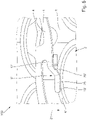
- FIG 3 schematically shows a perspective side view of a portion of the battery module arrangement 100 according to FIG figures 1 and 2 .
- Two hold-down devices 110 and a welding head 120 are shown schematically as an example.
- the hold-down devices 110 hold down the busbar 1, in other words press it onto the cell holder 2 shown here.
- the busbar 1 is held in a fixed position in relation to the cell holder 2 and thus to the battery cells 3 held therein, so that the welding head 120 can weld a contact connection 5, 5' to one of the battery cells 3.
- the weld is sufficient to hold the conductor rail 3 and to provide adequate contact.
- the first contacting connections 5 at the rear in the figure are shown here as already welded, for example, and the second ones at the front in perspective Contacting connections 5' are shown here as an example in a partially depressed position.
- a welding head 120 is only shown here as an example when pressing down a second contact connection 5' before the actual welding.
- one or more contact connections 5, 5' can be pressed down or welded at the same time.
- the busbar 1 is designed as an integral, two-dimensional sheet metal part.
- the contacting connections 5, 5' each have a contacting section 19 for contacting a cell contact 6, 6' and a deforming section 20, 20', the latter being able to move from the height level ( in the direction of thickness 21) of the base body 4 to a different height level (in the direction of thickness 21) of the cell contact 6, 6' to be contacted for contacting this cell contact 6, 6' undergoes a deformation, preferably an elastic and/or plastic deformation, in particular bending.
- the cell holder 2 optionally has a support area 22 on which the contacting connection 5, 5' to be pressed is supported with its root area 17, 17'.
- figure 4 shows a further perspective side view of the battery module arrangement according to the previous figures. This shows a connection area 13 of the busbar 1 with a first contact connection 5 on the first side 10 and a second contact connection 5 ′ on the second side 11 .
- the first contact connection 5 is in a state in which cell contact 6 has already been contacted.
- the spot weld 23 can be seen accordingly.
- the second contact connection 5' is still in its two-dimensional state, i.e. before it is formed in a production step by the welding head 120 (see figure 3 ) is pressed down and welded.
- the sections 19' and 20' are not yet formed as such, but are provided within the two-dimensional tab.
- figure 5 shows the perspective side view figure 4
- the second contacting connection 5 'out of the plane defined by the base body 4 via the Welding head 120 (see figure 3 ) was pressed onto the negative pole cell contact 6' and welded.
- the deformation section 20' extends in the thickness direction 21 from the level of the base body 4 to the level of the cell contact 6'.
- the contacting section 19′ also includes a spot weld 23, so that the contacting connection 5′ is permanently connected to the cell contact 6′ in a current-conducting manner.
Priority Applications (3)
| Application Number | Priority Date | Filing Date | Title |
|---|---|---|---|
| KR1020237042020A KR20240006060A (ko) | 2021-05-25 | 2022-05-25 | 셀 홀더에 수용된 배터리 셀들과 접촉하기 위한 버스 바, 배터리 모듈 장치, 및 배터리 셀에 버스 바를 연결하기 위한 방법 |
| CN202280037189.4A CN117461211A (zh) | 2021-05-25 | 2022-05-25 | 用于接触保持在单元支架中的电池单元的汇流轨、电池模块组件及将汇流轨与电池单元连接的方法 |
| PCT/EP2022/064310 WO2022248609A1 (fr) | 2021-05-25 | 2022-05-25 | Barre omnibus pour la mise en contact de cellules de batterie maintenues dans un support de cellules, ensemble module de batterie et procédé de connexion d'une barre omnibus à une cellule de batterie |
Applications Claiming Priority (1)
| Application Number | Priority Date | Filing Date | Title |
|---|---|---|---|
| DE102021113487.0A DE102021113487B3 (de) | 2021-05-25 | 2021-05-25 | Fixierung der Stromschienen beim Schweißprozess |
Publications (2)
| Publication Number | Publication Date |
|---|---|
| EP4096011A2 true EP4096011A2 (fr) | 2022-11-30 |
| EP4096011A3 EP4096011A3 (fr) | 2023-03-15 |
Family
ID=81580369
Family Applications (1)
| Application Number | Title | Priority Date | Filing Date |
|---|---|---|---|
| EP22171473.6A Pending EP4096011A3 (fr) | 2021-05-25 | 2022-05-03 | Barre omnibus permettant de mettre en contact des éléments de batterie retenues dans un porte-élément, agencement de module de batterie et procédé de connexion d'une barre omnibus à un élément de batterie |
Country Status (4)
| Country | Link |
|---|---|
| US (1) | US20220384888A1 (fr) |
| EP (1) | EP4096011A3 (fr) |
| CN (1) | CN115395181A (fr) |
| DE (1) | DE102021113487B3 (fr) |
Cited By (1)
| Publication number | Priority date | Publication date | Assignee | Title |
|---|---|---|---|---|
| DE102022122105A1 (de) | 2022-09-01 | 2024-03-07 | Bayerische Motoren Werke Aktiengesellschaft | Batteriezelle, System, Verfahren zur Herstellung eines Batteriezellverbunds und Batteriezellverbund |
Families Citing this family (1)
| Publication number | Priority date | Publication date | Assignee | Title |
|---|---|---|---|---|
| USD1012853S1 (en) * | 2020-03-24 | 2024-01-30 | Acer Incorporated | Battery holder |
Citations (3)
| Publication number | Priority date | Publication date | Assignee | Title |
|---|---|---|---|---|
| EP3790075A1 (fr) | 2019-09-09 | 2021-03-10 | Samsung SDI Co., Ltd. | Bloc-batterie |
| EP3800702A1 (fr) | 2019-02-22 | 2021-04-07 | Lg Chem, Ltd. | Barre omnibus pour connexion de cellule de batterie, bloc-batterie et son procédé de fabrication |
| WO2021182779A1 (fr) | 2020-03-09 | 2021-09-16 | 주식회사 엘지에너지솔루션 | Module de batterie comportant une barre omnibus, bloc-batterie et véhicule |
Family Cites Families (12)
| Publication number | Priority date | Publication date | Assignee | Title |
|---|---|---|---|---|
| DE19924529A1 (de) | 1999-05-28 | 2000-11-30 | David Bech | Temperatur- und mechanisch optimierter Akkumulator |
| DE202011109862U1 (de) | 2011-11-24 | 2012-05-21 | Bmz Batterien-Montage-Zentrum Gmbh | Energiespeicherhaltesystem mit integrierten elektrischen Verbindern |
| KR101720636B1 (ko) | 2012-11-30 | 2017-03-28 | 도요타 지도샤(주) | 축전 장치 |
| US9774024B2 (en) * | 2015-04-21 | 2017-09-26 | Atieva, Inc. | Preconditioned bus bar interconnect system |
| US10062931B2 (en) * | 2015-04-22 | 2018-08-28 | Johnson Controls Technology Company | Welding process for battery module components |
| US10193123B2 (en) * | 2016-03-01 | 2019-01-29 | Atieva, Inc. | Battery pack bus bar assembly with enlarged interconnect mounting platforms |
| DE102017117590B4 (de) | 2017-08-03 | 2019-03-14 | Karlsruher Institut für Technologie | Positionier-Hilfsvorrichtung |
| WO2019164974A1 (fr) * | 2018-02-20 | 2019-08-29 | Nio Usa, Inc. | Barre omnibus effilée à densité de courant uniforme |
| KR102259380B1 (ko) * | 2018-04-20 | 2021-06-01 | 주식회사 엘지에너지솔루션 | 버스바를 구비한 배터리 모듈 및 배터리 팩 |
| DE202018104526U1 (de) * | 2018-08-07 | 2019-11-12 | Webasto SE | Batteriemodul |
| JP6865724B2 (ja) * | 2018-10-10 | 2021-04-28 | 矢崎総業株式会社 | バスバーモジュールの組立方法 |
| EP3678213A1 (fr) * | 2019-01-07 | 2020-07-08 | Andreas Stihl AG & Co. KG | Structure support de cellule destinée à maintenir des cellules d'accumulateur |
-
2021
- 2021-05-25 DE DE102021113487.0A patent/DE102021113487B3/de active Active
-
2022
- 2022-05-03 EP EP22171473.6A patent/EP4096011A3/fr active Pending
- 2022-05-24 US US17/752,134 patent/US20220384888A1/en active Pending
- 2022-05-25 CN CN202210579132.9A patent/CN115395181A/zh active Pending
Patent Citations (3)
| Publication number | Priority date | Publication date | Assignee | Title |
|---|---|---|---|---|
| EP3800702A1 (fr) | 2019-02-22 | 2021-04-07 | Lg Chem, Ltd. | Barre omnibus pour connexion de cellule de batterie, bloc-batterie et son procédé de fabrication |
| EP3790075A1 (fr) | 2019-09-09 | 2021-03-10 | Samsung SDI Co., Ltd. | Bloc-batterie |
| WO2021182779A1 (fr) | 2020-03-09 | 2021-09-16 | 주식회사 엘지에너지솔루션 | Module de batterie comportant une barre omnibus, bloc-batterie et véhicule |
Cited By (1)
| Publication number | Priority date | Publication date | Assignee | Title |
|---|---|---|---|---|
| DE102022122105A1 (de) | 2022-09-01 | 2024-03-07 | Bayerische Motoren Werke Aktiengesellschaft | Batteriezelle, System, Verfahren zur Herstellung eines Batteriezellverbunds und Batteriezellverbund |
Also Published As
| Publication number | Publication date |
|---|---|
| DE102021113487B3 (de) | 2022-06-15 |
| EP4096011A3 (fr) | 2023-03-15 |
| CN115395181A (zh) | 2022-11-25 |
| US20220384888A1 (en) | 2022-12-01 |
Similar Documents
| Publication | Publication Date | Title |
|---|---|---|
| EP4096011A2 (fr) | Barre omnibus permettant de mettre en contact des éléments de batterie retenues dans un porte-élément, agencement de module de batterie et procédé de connexion d'une barre omnibus à un élément de batterie | |
| DE202018106375U1 (de) | Zellverbinder zum elektrisch leitenden Verbinden von Rundzellen einer Batterie für ein Kraftfahrzeug sowie entsprechende Batterie | |
| EP2713423B1 (fr) | Module de batterie avec elément de liaison en forme d'oméga pour relier électriquement des cellules de batterie | |
| EP3878024A1 (fr) | Connecteur de cellules servant à relier de manière électroconductrice des cellules rondes d'une batterie pour un véhicule automobile, et procédé de fabrication d'une batterie pour un véhicule automobile | |
| WO2017008947A1 (fr) | Système d'accumulateur avec une technique de soudure améliorée pour un élément de liaison de cellules | |
| DE102015200451A1 (de) | Flexibler Sammelschienenhalter für geschweißte Zellen | |
| DE102018132147A1 (de) | Verfahren zum bilden einer sammelschiene und gefaltete sammelschiene | |
| WO2018219966A1 (fr) | Élément de mise en contact pour un système de mise en contact de cellules pour un dispositif électrochimique et procédé servant à fabriquer un système de mise en contact de cellules pour un dispositif électrochimique | |
| WO2022248609A1 (fr) | Barre omnibus pour la mise en contact de cellules de batterie maintenues dans un support de cellules, ensemble module de batterie et procédé de connexion d'une barre omnibus à une cellule de batterie | |
| EP3707764A1 (fr) | Procédé de fabrication d'une plaque de contact pour un empilement de batteries, plaque de contact pour un empilement de batteries ainsi qu'empilement de batteries | |
| DE102012200591A1 (de) | Energiemodul für einen elektrischen Energiespeicher für ein Fahrzeug und Verfahren zur Herstellung des Energiemoduls | |
| WO2015074735A1 (fr) | Batterie comportant une pluralité d'éléments de batterie à pôles reliés par des éléments de liaison | |
| EP2956976B1 (fr) | Élément de connexion d'éléments servant à relier de manière électriquement conductrice une pluralité de bornes d'éléments de batterie, procédé de fabrication d'un tel élément de connexion d'éléments et bloc batterie comprenant au moins un tel élément de connexion d'éléments | |
| WO2018130359A1 (fr) | Batterie, plaque de support et élément de plaque de support à éléments d'encliquetage | |
| EP0772251A1 (fr) | Cellule galvanique avec des collecteurs de courant d'électrodes sous forme de fils | |
| DE102019120497A1 (de) | Zellkontaktierungsmittel und batteriesystem | |
| DE102019120496A1 (de) | Anschlusselement zur elektrischen kontaktierung und verfarhen zur herstellung eines anschlusselements | |
| DE102019005440B3 (de) | Verfahren zum Herstellen eines Batteriemoduls, Batteriezelle sowie Batteriemodul | |
| DE102013213710A1 (de) | Batteriesystem und Verfahren zur Herstellung eines Batteriesystems | |
| DE102017128438A1 (de) | Zellverbinder, energiespeicher für ein fahrzeug sowie herstellungsverfahren | |
| DE102022106554B3 (de) | Batteriezelle und Batterieanordnung | |
| WO2022214259A1 (fr) | Accumulateur d'énergie électrique doté d'un système de contact à cellules latérales et véhicule à moteur | |
| DE102021113648A1 (de) | Vorrichtung und Verfahren zu einem Kontaktierungsbaukasten für Energiespeicherzellen einer Hochvolt-Batterie | |
| DE102011086303A1 (de) | Verfahren, sowie Energiespeicherzelle, zur Herstellung einer elektrischen Energiespeichereinheit | |
| DE102021113215A1 (de) | Flächenarm bauender Zellverbinder und Herstellverfahren |
Legal Events
| Date | Code | Title | Description |
|---|---|---|---|
| PUAI | Public reference made under article 153(3) epc to a published international application that has entered the european phase |
Free format text: ORIGINAL CODE: 0009012 |
|
| STAA | Information on the status of an ep patent application or granted ep patent |
Free format text: STATUS: THE APPLICATION HAS BEEN PUBLISHED |
|
| AK | Designated contracting states |
Kind code of ref document: A2 Designated state(s): AL AT BE BG CH CY CZ DE DK EE ES FI FR GB GR HR HU IE IS IT LI LT LU LV MC MK MT NL NO PL PT RO RS SE SI SK SM TR |
|
| PUAL | Search report despatched |
Free format text: ORIGINAL CODE: 0009013 |
|
| AK | Designated contracting states |
Kind code of ref document: A3 Designated state(s): AL AT BE BG CH CY CZ DE DK EE ES FI FR GB GR HR HU IE IS IT LI LT LU LV MC MK MT NL NO PL PT RO RS SE SI SK SM TR |
|
| RIC1 | Information provided on ipc code assigned before grant |
Ipc: H01M 50/213 20210101ALI20230208BHEP Ipc: H01M 50/509 20210101ALI20230208BHEP Ipc: H01M 50/516 20210101ALI20230208BHEP Ipc: H01M 50/503 20210101AFI20230208BHEP |
|
| STAA | Information on the status of an ep patent application or granted ep patent |
Free format text: STATUS: REQUEST FOR EXAMINATION WAS MADE |
|
| 17P | Request for examination filed |
Effective date: 20230915 |
|
| RBV | Designated contracting states (corrected) |
Designated state(s): AL AT BE BG CH CY CZ DE DK EE ES FI FR GB GR HR HU IE IS IT LI LT LU LV MC MK MT NL NO PL PT RO RS SE SI SK SM TR |