EP4096011A2 - Bus bar for contacting battery cells held in a cell holder, battery module assembly and method for connecting a bus bar to a battery cell - Google Patents
Bus bar for contacting battery cells held in a cell holder, battery module assembly and method for connecting a bus bar to a battery cell Download PDFInfo
- Publication number
- EP4096011A2 EP4096011A2 EP22171473.6A EP22171473A EP4096011A2 EP 4096011 A2 EP4096011 A2 EP 4096011A2 EP 22171473 A EP22171473 A EP 22171473A EP 4096011 A2 EP4096011 A2 EP 4096011A2
- Authority
- EP
- European Patent Office
- Prior art keywords
- connection
- contact
- contacting
- cell
- battery
- Prior art date
- Legal status (The legal status is an assumption and is not a legal conclusion. Google has not performed a legal analysis and makes no representation as to the accuracy of the status listed.)
- Pending
Links
Images


Classifications
-
- H—ELECTRICITY
- H01—ELECTRIC ELEMENTS
- H01M—PROCESSES OR MEANS, e.g. BATTERIES, FOR THE DIRECT CONVERSION OF CHEMICAL ENERGY INTO ELECTRICAL ENERGY
- H01M50/00—Constructional details or processes of manufacture of the non-active parts of electrochemical cells other than fuel cells, e.g. hybrid cells
- H01M50/50—Current conducting connections for cells or batteries
- H01M50/502—Interconnectors for connecting terminals of adjacent batteries; Interconnectors for connecting cells outside a battery casing
- H01M50/507—Interconnectors for connecting terminals of adjacent batteries; Interconnectors for connecting cells outside a battery casing comprising an arrangement of two or more busbars within a container structure, e.g. busbar modules
-
- H—ELECTRICITY
- H01—ELECTRIC ELEMENTS
- H01M—PROCESSES OR MEANS, e.g. BATTERIES, FOR THE DIRECT CONVERSION OF CHEMICAL ENERGY INTO ELECTRICAL ENERGY
- H01M50/00—Constructional details or processes of manufacture of the non-active parts of electrochemical cells other than fuel cells, e.g. hybrid cells
- H01M50/50—Current conducting connections for cells or batteries
- H01M50/528—Fixed electrical connections, i.e. not intended for disconnection
-
- H—ELECTRICITY
- H01—ELECTRIC ELEMENTS
- H01M—PROCESSES OR MEANS, e.g. BATTERIES, FOR THE DIRECT CONVERSION OF CHEMICAL ENERGY INTO ELECTRICAL ENERGY
- H01M50/00—Constructional details or processes of manufacture of the non-active parts of electrochemical cells other than fuel cells, e.g. hybrid cells
- H01M50/20—Mountings; Secondary casings or frames; Racks, modules or packs; Suspension devices; Shock absorbers; Transport or carrying devices; Holders
- H01M50/204—Racks, modules or packs for multiple batteries or multiple cells
- H01M50/207—Racks, modules or packs for multiple batteries or multiple cells characterised by their shape
- H01M50/213—Racks, modules or packs for multiple batteries or multiple cells characterised by their shape adapted for cells having curved cross-section, e.g. round or elliptic
-
- H—ELECTRICITY
- H01—ELECTRIC ELEMENTS
- H01M—PROCESSES OR MEANS, e.g. BATTERIES, FOR THE DIRECT CONVERSION OF CHEMICAL ENERGY INTO ELECTRICAL ENERGY
- H01M50/00—Constructional details or processes of manufacture of the non-active parts of electrochemical cells other than fuel cells, e.g. hybrid cells
- H01M50/20—Mountings; Secondary casings or frames; Racks, modules or packs; Suspension devices; Shock absorbers; Transport or carrying devices; Holders
- H01M50/249—Mountings; Secondary casings or frames; Racks, modules or packs; Suspension devices; Shock absorbers; Transport or carrying devices; Holders specially adapted for aircraft or vehicles, e.g. cars or trains
-
- H—ELECTRICITY
- H01—ELECTRIC ELEMENTS
- H01M—PROCESSES OR MEANS, e.g. BATTERIES, FOR THE DIRECT CONVERSION OF CHEMICAL ENERGY INTO ELECTRICAL ENERGY
- H01M50/00—Constructional details or processes of manufacture of the non-active parts of electrochemical cells other than fuel cells, e.g. hybrid cells
- H01M50/50—Current conducting connections for cells or batteries
- H01M50/502—Interconnectors for connecting terminals of adjacent batteries; Interconnectors for connecting cells outside a battery casing
- H01M50/503—Interconnectors for connecting terminals of adjacent batteries; Interconnectors for connecting cells outside a battery casing characterised by the shape of the interconnectors
-
- H—ELECTRICITY
- H01—ELECTRIC ELEMENTS
- H01M—PROCESSES OR MEANS, e.g. BATTERIES, FOR THE DIRECT CONVERSION OF CHEMICAL ENERGY INTO ELECTRICAL ENERGY
- H01M50/00—Constructional details or processes of manufacture of the non-active parts of electrochemical cells other than fuel cells, e.g. hybrid cells
- H01M50/50—Current conducting connections for cells or batteries
- H01M50/502—Interconnectors for connecting terminals of adjacent batteries; Interconnectors for connecting cells outside a battery casing
- H01M50/505—Interconnectors for connecting terminals of adjacent batteries; Interconnectors for connecting cells outside a battery casing comprising a single busbar
-
- H—ELECTRICITY
- H01—ELECTRIC ELEMENTS
- H01M—PROCESSES OR MEANS, e.g. BATTERIES, FOR THE DIRECT CONVERSION OF CHEMICAL ENERGY INTO ELECTRICAL ENERGY
- H01M50/00—Constructional details or processes of manufacture of the non-active parts of electrochemical cells other than fuel cells, e.g. hybrid cells
- H01M50/50—Current conducting connections for cells or batteries
- H01M50/502—Interconnectors for connecting terminals of adjacent batteries; Interconnectors for connecting cells outside a battery casing
- H01M50/514—Methods for interconnecting adjacent batteries or cells
- H01M50/516—Methods for interconnecting adjacent batteries or cells by welding, soldering or brazing
-
- H—ELECTRICITY
- H01—ELECTRIC ELEMENTS
- H01M—PROCESSES OR MEANS, e.g. BATTERIES, FOR THE DIRECT CONVERSION OF CHEMICAL ENERGY INTO ELECTRICAL ENERGY
- H01M50/00—Constructional details or processes of manufacture of the non-active parts of electrochemical cells other than fuel cells, e.g. hybrid cells
- H01M50/50—Current conducting connections for cells or batteries
- H01M50/502—Interconnectors for connecting terminals of adjacent batteries; Interconnectors for connecting cells outside a battery casing
- H01M50/521—Interconnectors for connecting terminals of adjacent batteries; Interconnectors for connecting cells outside a battery casing characterised by the material
- H01M50/522—Inorganic material
-
- H—ELECTRICITY
- H01—ELECTRIC ELEMENTS
- H01R—ELECTRICALLY-CONDUCTIVE CONNECTIONS; STRUCTURAL ASSOCIATIONS OF A PLURALITY OF MUTUALLY-INSULATED ELECTRICAL CONNECTING ELEMENTS; COUPLING DEVICES; CURRENT COLLECTORS
- H01R43/00—Apparatus or processes specially adapted for manufacturing, assembling, maintaining, or repairing of line connectors or current collectors or for joining electric conductors
- H01R43/02—Apparatus or processes specially adapted for manufacturing, assembling, maintaining, or repairing of line connectors or current collectors or for joining electric conductors for soldered or welded connections
- H01R43/0263—Apparatus or processes specially adapted for manufacturing, assembling, maintaining, or repairing of line connectors or current collectors or for joining electric conductors for soldered or welded connections for positioning or holding parts during soldering or welding process
-
- H—ELECTRICITY
- H02—GENERATION; CONVERSION OR DISTRIBUTION OF ELECTRIC POWER
- H02G—INSTALLATION OF ELECTRIC CABLES OR LINES, OR OF COMBINED OPTICAL AND ELECTRIC CABLES OR LINES
- H02G5/00—Installations of bus-bars
-
- H—ELECTRICITY
- H01—ELECTRIC ELEMENTS
- H01M—PROCESSES OR MEANS, e.g. BATTERIES, FOR THE DIRECT CONVERSION OF CHEMICAL ENERGY INTO ELECTRICAL ENERGY
- H01M2220/00—Batteries for particular applications
- H01M2220/20—Batteries in motive systems, e.g. vehicle, ship, plane
-
- Y—GENERAL TAGGING OF NEW TECHNOLOGICAL DEVELOPMENTS; GENERAL TAGGING OF CROSS-SECTIONAL TECHNOLOGIES SPANNING OVER SEVERAL SECTIONS OF THE IPC; TECHNICAL SUBJECTS COVERED BY FORMER USPC CROSS-REFERENCE ART COLLECTIONS [XRACs] AND DIGESTS
- Y02—TECHNOLOGIES OR APPLICATIONS FOR MITIGATION OR ADAPTATION AGAINST CLIMATE CHANGE
- Y02E—REDUCTION OF GREENHOUSE GAS [GHG] EMISSIONS, RELATED TO ENERGY GENERATION, TRANSMISSION OR DISTRIBUTION
- Y02E60/00—Enabling technologies; Technologies with a potential or indirect contribution to GHG emissions mitigation
- Y02E60/10—Energy storage using batteries
Definitions
- the present invention relates to an improved busbar for contacting held in a cell holder, for example cylindrical, battery cells to form a battery module of a high-voltage battery, such as a traction battery for a vehicle, and a corresponding battery module arrangement for forming a high-voltage battery, such as a traction battery for a vehicle, and a method for connecting a bus bar to a cell contact of a battery cell in a battery module assembly.
- a high-voltage battery such as a traction battery for a vehicle
- a corresponding battery module arrangement for forming a high-voltage battery, such as a traction battery for a vehicle
- High-voltage batteries are known from the prior art, the battery cells of which are connected to busbars, also known as current collectors or busbars. Batteries are also referred to as accumulators. These are usually electrochemical accumulators, in particular lithium-ion accumulators. Batteries of this type are usually not constructed as a monoblock, but in a modular manner from a large number of battery cells which are mechanically and electrically connected to one another. For the construction of a battery system in an electric vehicle, it is correspondingly known to arrange battery cells in battery modules and to assemble these to form a battery. This increases the configurability of batteries and enables the use of comparatively inexpensive standard battery cells when constructing batteries. The battery cells of a battery module can be held by a cell holder.
- This is a body extending in a plane of extension, which is usually made of a non-conductive material such as plastic, and which usually comprises a large number of receptacles arranged in a predetermined pattern in relation to the plane of extension for accommodating a battery cell.
- a battery cell is understood to be an electrochemical storage cell, preferably a secondary cell.
- the term "cell” can be understood as the smallest contactable structural unit.
- a battery module is understood to be a structural unit that combines a large number of battery cells.
- a battery is accordingly understood to mean a structural unit that is made up of one or more interconnected battery modules.
- Such batteries can include a housing accommodating the battery modules, electrical interconnections and a battery management system. A number of batteries can be interconnected to form a battery system, for example in order to provide an increased capacity of the battery system.
- the battery or the battery system is preferably intended for use in an electric vehicle, but can also be used in other vehicles or other areas of application.
- busbars are welded directly to battery cells, busbars are preformed accordingly so that the sections of the busbar intended for connection to the cells touch the cells in order to be able to be welded to them.
- Preforming is an additional manufacturing step. After a two-dimensional busbar preform has been punched out or cut free from sheet metal, this preform has to be brought into a three-dimensional shape in a further deformation step, for example a deep-drawing or bending step.
- contacting connections in the form of branches that extend three-dimensionally from an elongated main body of the busbar are usually welded directly to the cell contact to be contacted of the respective battery cell using ultrasonic or laser welding.
- these branches extend perpendicularly to the main extension direction of the base body of the busbar, which usually corresponds to a main load direction or a main load path and in which a plurality of battery cells arranged one behind the other are connected in parallel via the busbar.
- the branches for contacting the positive pole of the battery cells extend at a 90° angle from the base body radially to the center of the end face of the cylindrical battery cell having the positive pole there.
- To contact the negative pole they usually run at a 90° angle from the base body tangential to the beaded edge of the end face of the cylindrical battery cell having the negative pole there.
- a battery module arrangement with a conventional busbar with perpendicularly extending from a base contact connections can, for example WO 2021 182 779 A1 , the EP 3 800 702 A1 or the EP 3 790 075 A1 be removed.
- the material utilization in the production of such busbars as a stamped part or a free-cut part is low in the case of branching off contact connections at a 90° angle.
- a hexagonal arrangement of the battery cells also called cell packing, which offers the best use of space, for example with cylindrical battery cells, the electrical connection path between serially connected battery cells is comparatively large, so that the resistance between them is also unnecessarily large.
- a cylindrical battery cell has a pole on its end face in the area of its beaded edge, the electrical contacting of this beaded edge via a contact connection extending perpendicularly from the base body allows only extremely small positional tolerances of the battery cell in relation to the main direction of extension, i.e. in the direction of a row of battery cells connected in parallel.
- an object of the present invention to provide an improved busbar for contacting preferably cylindrical battery cells held in a cell holder to form a battery module of a high-voltage battery, preferably a traction battery for a vehicle, and a corresponding battery module arrangement for forming a high-voltage battery, preferably a traction battery for a vehicle and a method for connecting a busbar to a cell contact of a battery cell.
- a busbar for contacting preferably cylindrical battery cells held in a cell holder to form a battery module of a high-voltage battery, preferably a traction battery for a vehicle, with the features of claim 1.
- a busbar for contacting preferably cylindrical battery cells held in a cell holder to form a battery module of a high-voltage battery, preferably a traction battery for a vehicle, comprising a main body extending in a main extension direction and at least one contacting connection formed in one piece with the main body for contacting a cell contact of one of the battery cells.
- the busbar is designed in such a way that the contacting connection extends in a connection extension direction, which encloses a connection angle of between 0° and less than 90° with the main extension direction, with the busbar preferably having a plurality of the aforementioned contacting connections.
- connection angle is understood to mean the angle that is enclosed by the projection of the connection extension direction and the projection of the main extension direction onto a plane in which the base body extends.
- the plane is defined by the two-dimensional extension of the sheet metal/base body, ie perpendicular to the thickness direction of the sheet metal/base body.
- the contacting connection extends in a connection extension direction, which encloses a connection angle of between 0° and less than 90° with the main extension direction, a particularly high material utilization can be achieved in the production of the busbar, in particular if this is a stamped part or free-cut part made of a ( sheet metal is punched or cut. This is because the contacting connections are spatially close to the base body, in contrast to conventional busbars described in the prior art with contacting connections extending perpendicularly to the main direction of extension.
- the electrical connection path between two battery cells connected in series by the busbar can be kept particularly short, even as short as possible, and accordingly the electrical resistance can therefore be particularly small, even be kept as low as possible.
- the design of the busbar in this way allows the covering of the upper side of the battery cells by the cell holder and busbar to be minimized, so that a particularly effective, even a venting or "venting" of the battery cell(s) that is essentially not prevented by the busbar is made possible in the event of a fault.
- the contacting connection is provided for contacting a cell contact arranged in the area of the circumference of an end face of a cylindrical battery cell, i.e. on its flanged edge, which can be designed, for example, as the negative pole of the battery cell, a high positional tolerance with regard to the position of the busbar and so that the contacting connection on the one hand and the battery cell on the other hand can be achieved in the main extension direction.
- the main direction of extension is arranged in the direction of a parallel connection of battery cells, this enables correspondingly larger positional tolerances of the battery cells connected in parallel in the main direction of extension, and thus, for example, varying distances between the battery cells in the main direction of extension due to manufacturing tolerances of the cell holder.
- the busbar according to the invention therefore allows simpler and more robust (series) production, a simpler design and less material use with regard to the busbar itself and in particular the cell holder and the battery module arrangement.
- connection extension direction is preferably oriented in such a way or the contacting connection extending in the connection extension direction extends in such a way that the cell contact to be contacted by this contacting connection is contacted tangentially to a central axis of the battery cell having the cell contact. So a comparatively large possible position tolerance with respect to the busbar compared to the contacting battery cells and between the battery cells are provided relative to each other.
- the main extension direction is preferably oriented in the main load direction, ie in the direction of a parallel connection of a plurality of battery cells.
- the base body In its main extension direction, the base body has a length that is many times greater than its width transversely to the main extension direction.
- the basic body can be designed as a strip or web. This results in the elongated "rail shape" of the busbar.
- the attachment angle ⁇ is less than 45°, preferably less than 40°, particularly preferably less than 35°, particularly preferably less than 30°, the attachment angle preferably being 25°, 20°, 15°, 10°, 5° or is 0°.
- the smaller the connection angle the greater the available positional tolerances in the main direction of extension.
- the potential degree of material utilization increases with decreasing connection angle, for example if the conductor rail is sheared/cut from sheet metal.
- the length of a current path provided between two series-connected battery cells via the busbar can be made all the smaller, the smaller the connection angle.
- connection angle increases, the distance between two rows of battery cells can be greater transversely to the main extension direction and/or the width of the base body can be made smaller, so that material can be saved with regard to the busbar itself.
- angle of attack range of 0° to 45°, in particular at 0° and 25°.
- the contacting connection extends laterally from the base body in the form of a tab in the connection extension direction in relation to the main extension direction.
- the at least one contact connection is provided laterally on the base body in relation to the main direction of extent.
- the busbar comprises at least one first contact connection for contacting a cell contact of a first polarity of a first battery cell and at least one second contact connection for contacting a Cell contact of the second polarity of a second battery cell.
- the busbar preferably includes a plurality of first and/or second contacting connections.
- the at least one first contact connection is arranged on a first side of the base body and the at least one second contact connection is arranged on a second side of the base body.
- the first contact connection is designed to contact a cell contact of the first polarity arranged centrally on one end face of a battery cell and/or if the second contact connection is designed to contact a second cell contact arranged on the end face of another battery cell in the peripheral region contact polarity.
- the first contacting connection extends from the base body in a first direction relative to the main extension direction and the second contacting connection extends from the base body in a second direction opposite the first direction relative to the main extension direction.
- directional sense related to the main direction of extent here means that this sense of direction comprises at least one component that runs in the direction of the main extent.
- the sense of direction corresponds to a vector, starting at the base or foot or root section of the contact connection on the base body and extending in the direction of the free end of this contact connection.
- the sense of direction can be determined as the component of the attachment direction of extension, which is parallel to the main direction of extension.
- a particularly short current path can be achieved between two series-connected battery cells.
- the first contacting connection extends in a first direction from the base body and the second contacting connection in a second direction, oriented opposite to the first direction, from the base body.
- the base body can be designed with a comparatively small width and thus the material requirements for the busbar can be comparatively small.
- a root section of the first contacting connection, from which the first contacting connection extends from the base body, and a root section of the second contacting connection, from which the second contacting connection extends from the base body are essentially the same in relation to the main direction of extent arranged at height.
- a particularly short current path can thus be achieved between two battery cells connected in series by means of the busbar.
- “Essentially at the same height” is defined as lying within specified tolerances, within which the offset of the root sections, more precisely from the center, in the main extension direction is less than or equal to the width of the tabs transverse to their connection extension direction.
- the base body and the contact connections are designed as a one-piece, ie integral, two-dimensional sheet metal part.
- the busbar is preferably a two-dimensional sheet metal part.
- the at least one contacting connection has a contacting section for contacting a cell contact and in each case a deforming section, via which, when the contacting section is pressed down in a thickness direction of the base body from the height level of the base body to a different height level of the cell contact to be contacted, for contacting of the cell contact, a deformation, preferably an elastic and/or plastic deformation, preferably comprising a bend, can be accommodated.
- the busbar can be designed as a two-dimensional sheet metal part, in which case the at least one contact connection can be deformed in order to physically touch the cell contact to be contacted and the contact can be made in one work step in order to form a permanent, electrically conductive connection between the contact connection and the cell contact.
- the base body comprises an S-shaped transition section between two connection areas, from which at least one contacting connection extends, with each connection area preferably having one have a predetermined width transverse to the direction of main extension and the transition section has a width transverse to which is smaller than the width of the connection areas, wherein the transition section preferably has a length in the direction of main extension that is greater than the length of two contacting connections in the direction of main extension.
- the conductor rail can thus be designed to be particularly material-saving.
- the main body of material includes recessed areas in which a contacting connection can extend in its respective connection angle, preferably 0° for contacting a cell contact in the peripheral area or 25° for contacting a centrally arranged cell contact, without the overall width of the conductor rail to increase significantly.
- a connection area preferably comprises a first and a second contact connection.
- a battery module arrangement for forming a high-voltage battery, preferably a traction battery for a vehicle, with the features of claim 10.
- a battery module arrangement for forming a high-voltage battery preferably a traction battery for a vehicle, comprising a cell holder, a multiplicity of battery cells held in the cell holder and a busbar according to one of the above embodiments.
- busbar can be achieved in an analogous manner by the battery module arrangement, which is why they are not described again here in order to avoid redundancies.
- a method for connecting a busbar to a cell contact of a battery cell comprising bringing together a cell holder for holding battery cells in a battery module with a busbar according to one of the above Embodiments, holding down the busbar with at least one hold-down device, pressing on a contacting connection of the busbar to contact a battery cell held in the cell holder, and welding the contacting connection to the battery cell.
- the method makes it possible, preferably in conjunction with a correspondingly designed support geometry on the cell holder, to bend down the contact connection(s) to the contact surface of the cell contact to be contacted in the same process step with the electrical contact, preferably by laser or ultrasonic welding.
- the busbar By manufacturing the busbar as a purely two-dimensional stamped part or free-cut part, instead of a three-dimensional stamped and bent part, as is the case with conventional methods, the manufacture, handling and, above all, the placement of the busbar on the cell holder and the tolerances to be observed in this regard without inadvertently making electrical contact with the cells before the actual welding process.
- a contacting section of the contacting connection is pressed from a plane defined by the base body of the busbar onto the cell contact of the battery cell to be contacted, with a deformation section of the contacting connection preferably undergoing elastic and/or plastic deformation.
- the contacting connection is pressed onto a battery cell by means of a welding head, which is also used for the immediately following welding of the contacting connection and cell contact.
- both the pressing down or pressing preferably with deformation of the contact connection, preferably its deformation section, from the plane defined by the base body, onto the cell contact of the battery cell to be contacted in one step with the welding of the contact connection and cell contact by a single specially designed tool.
- the welding head is therefore designed to be pressed on the contact connection to and for welding the contact connection to the cell contact.
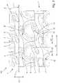
- FIG 1 1 is a schematic plan view of a battery module assembly 100 for forming a high-voltage traction battery of a vehicle. It includes a cell holder, not shown here for reasons of clarity (see Figures 3 to 5 , reference number 2 there), which has a multiplicity of receptacles, in each of which a cylindrical battery cell 3 is accommodated.
- the receptacles of the cell holder 2 are arranged in such a way that the battery cells 3 are arranged perpendicularly to the (longitudinal) central axes 9 in a hexagonal pattern. They therefore represent a hexagonal cell packing.
- the battery module arrangement 100 also includes a plurality of busbars 1 running parallel, which are designed to contact a plurality of the battery cells 3 held in the cell holder 2.
- the busbar 1 comprises a base body 4 extending in a main direction of extension 7 and a plurality of contacting connections 5, 5′ formed in one piece with the base body 4 for contacting one cell contact 6, 6′ of one battery cell 3.
- the main extension direction 7 corresponds to a direction in which battery cells are arranged one behind the other in a row. These are connected in parallel by the conductor rail 1, as explained in more detail below.
- the contact connections 5, 5' are divided into a plurality of first contact connections 5 for contacting a cell contact 6 of a first polarity in each case of a battery cell 3, here the one on in the plan view figure 1 visible end face of the respective battery cell 3 centrally arranged positive pole cell contact 6, and in a plurality of second contact connections 5 'for contacting a cell contact 6' of the second polarity of a battery cell 3, here the arranged on the end face of the respective battery cell 3 in the peripheral area negative pole cell contact 6'.
- first contacting connections 5 are arranged on a first side 10 of the base body 4 laterally on the base body 4 and the second contacting connections 5' are arranged on the other (second) side 11 of the base body 4 laterally on the base body 4.
- the direction of main extent 7 corresponds to the main load direction, i.e. the direction of a parallel connection of a plurality of battery cells 3 each whose positive pole cell contact 6 is electrically connected in parallel, and on the second side 11 through the second contacting connections 5 ′, a further plurality of battery cells 3 arranged in the main extension direction 7 are electrically connected in parallel by contacting their negative pole cell contact 6 ′.
- two battery cells 3 are electrically connected in series in each case by a first contact connection 5 and a second contact connection 5', as in relation to FIG figure 2 explained in more detail.
- connection connections 5, 5' each extend in a connection extension direction 8, 8', which encloses a connection angle ⁇ between 0° and less than 90° with the main extension direction 7.
- the first contact connections 5 have a connection extension direction 8 which is oriented at an attachment angle ⁇ of 25° relative to the main extension direction 7 .
- the second contact connections have a connection extension direction 8′, which is oriented parallel to the main extension direction 7, thus with a connection angle of 0°.
- connection angles ⁇ of the first and second contacting connections 5, 5' are therefore different. Alternatively, they can also have the same attachment angle ⁇ .
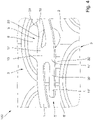
- Figure 12 is a schematic detail view of the plan view figure 1 shown.
- the first contact connections 5 or their connection extension direction 8 extend in a first direction from the base body 4 in relation to the main extension direction 7.
- the second contact connections 5' also extend in relation to the main extension direction 7 or their connection extension directions 8' in a second direction oriented opposite to the first direction of the base body 4.
- each busbar 1 can be considered to be essentially divided into two alternating areas or sections in the main extension direction 7 , namely a connection area 13 and a transition section 14 .
- An S-shaped transition section 14 is arranged between each of two connection areas 13, from which a first contact connection 5 and a second contact connection 5' extend.
- the connection areas 13 have a predetermined width transverse to the main extension direction 7 (ie in the transverse direction 12).
- the transition sections 14 also have a width transverse to the main extension direction 7 that is smaller than the width of the connection areas 13.
- a length 16 of the transition sections 14 in the main extension direction 7 is greater than the sum of the length 15 of the first Contacting connection 5 and the length 15' of the second contacting connection 5' in the main direction of extension 7.
- the busbar 1 or its base body 4 has material-free receiving areas in which a contacting connection 5, 5' can extend.
- the contacting sections 5, 5' are designed in the form of a tab. They extend, starting from a root section 17, 17', with which they are connected in one piece to the base body 4, in the direction of their connection extension direction 8, 8'. In relation to a connection area 13, the root sections 17, 17' of the pair of first and second contact connections 5, 5' extending there are arranged essentially at the same height in relation to the main direction of extension 7. This results in a particularly short current path 18 between two series-connected battery cells 3.
- connection extension directions 8, 8' of the contacting connections 5, 5' are oriented in such a way or the latter extend in the connection extension direction 8, 8' in such a way that contacting of the cell contact 6, 6 'tangentially to a central axis 9 of the respective cell contact 6, 6' having battery cell 3 is reached.
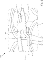
- FIG 3 schematically shows a perspective side view of a portion of the battery module arrangement 100 according to FIG figures 1 and 2 .
- Two hold-down devices 110 and a welding head 120 are shown schematically as an example.
- the hold-down devices 110 hold down the busbar 1, in other words press it onto the cell holder 2 shown here.
- the busbar 1 is held in a fixed position in relation to the cell holder 2 and thus to the battery cells 3 held therein, so that the welding head 120 can weld a contact connection 5, 5' to one of the battery cells 3.
- the weld is sufficient to hold the conductor rail 3 and to provide adequate contact.
- the first contacting connections 5 at the rear in the figure are shown here as already welded, for example, and the second ones at the front in perspective Contacting connections 5' are shown here as an example in a partially depressed position.
- a welding head 120 is only shown here as an example when pressing down a second contact connection 5' before the actual welding.
- one or more contact connections 5, 5' can be pressed down or welded at the same time.
- the busbar 1 is designed as an integral, two-dimensional sheet metal part.
- the contacting connections 5, 5' each have a contacting section 19 for contacting a cell contact 6, 6' and a deforming section 20, 20', the latter being able to move from the height level ( in the direction of thickness 21) of the base body 4 to a different height level (in the direction of thickness 21) of the cell contact 6, 6' to be contacted for contacting this cell contact 6, 6' undergoes a deformation, preferably an elastic and/or plastic deformation, in particular bending.
- the cell holder 2 optionally has a support area 22 on which the contacting connection 5, 5' to be pressed is supported with its root area 17, 17'.
- figure 4 shows a further perspective side view of the battery module arrangement according to the previous figures. This shows a connection area 13 of the busbar 1 with a first contact connection 5 on the first side 10 and a second contact connection 5 ′ on the second side 11 .
- the first contact connection 5 is in a state in which cell contact 6 has already been contacted.
- the spot weld 23 can be seen accordingly.
- the second contact connection 5' is still in its two-dimensional state, i.e. before it is formed in a production step by the welding head 120 (see figure 3 ) is pressed down and welded.
- the sections 19' and 20' are not yet formed as such, but are provided within the two-dimensional tab.
- figure 5 shows the perspective side view figure 4
- the second contacting connection 5 'out of the plane defined by the base body 4 via the Welding head 120 (see figure 3 ) was pressed onto the negative pole cell contact 6' and welded.
- the deformation section 20' extends in the thickness direction 21 from the level of the base body 4 to the level of the cell contact 6'.
- the contacting section 19′ also includes a spot weld 23, so that the contacting connection 5′ is permanently connected to the cell contact 6′ in a current-conducting manner.
Abstract
Die vorliegende Erfindung betrifft eine Stromschiene (1) zum Kontaktieren von in einem Zellhalter (2) gehaltenen, bevorzugt zylindrischen, Batteriezellen (3) zur Ausbildung eines Batteriemoduls (100) einer Hochvolt-Batterie, bevorzugt einer Traktionsbatterie für ein Fahrzeug, umfassend einen sich in einer Haupterstreckungsrichtung (7) erstreckender Grundkörper (4) und mindestens eine mit dem Grundkörper (4) einstückig ausgebildete Kontaktierungsanbindung (5, 5') zum Kontaktieren eines Zellkontaktes (6) einer der Batteriezellen (3), wobei die Kontaktierungsanbindung (5, 5') sich in einer Anbindungserstreckungsrichtung (8, 8') erstreckt, welche mit der Haupterstreckungsrichtung (7) einen Anbindungswinkel (a) zwischen 0° und kleiner 90° einschließt; sie betrifft ferner eine Batteriemodulanordnung (100) mit einer derartigen Stromschiene (1) und ein Verfahren zum Verbinden einer Stromschiene (1) mit einem Zellkontakt (6, 6').The present invention relates to a busbar (1) for contacting preferably cylindrical battery cells (3) held in a cell holder (2) to form a battery module (100) of a high-voltage battery, preferably a traction battery for a vehicle, comprising a A main body (4) extending in a main extension direction (7) and at least one contacting connection (5, 5') formed in one piece with the main body (4) for contacting a cell contact (6) of one of the battery cells (3), the contacting connection (5, 5' ) extends in a connection extension direction (8, 8') which encloses a connection angle (a) between 0° and less than 90° with the main extension direction (7); it also relates to a battery module arrangement (100) with such a busbar (1) and a method for connecting a busbar (1) to a cell contact (6, 6').
Description
Die vorliegende Erfindung betrifft eine verbesserte Stromschiene zum Kontaktieren von in einem Zellhalter gehaltenen, beispielsweise zylindrischen, Batteriezellen zur Ausbildung eines Batteriemoduls einer Hochvolt-Batterie, etwa einer Traktionsbatterie für ein Fahrzeug, sowie eine entsprechende Batteriemodulanordnung zum Ausbilden einer Hochvolt-Batterie, etwa einer Traktionsbatterie für ein Fahrzeug, und ein Verfahren zum Verbinden einer Stromschiene mit einem Zellkontakt einer Batteriezelle in einer Batteriemodulanordnung.The present invention relates to an improved busbar for contacting held in a cell holder, for example cylindrical, battery cells to form a battery module of a high-voltage battery, such as a traction battery for a vehicle, and a corresponding battery module arrangement for forming a high-voltage battery, such as a traction battery for a vehicle, and a method for connecting a bus bar to a cell contact of a battery cell in a battery module assembly.
Aus dem Stand der Technik sind Hochvolt-Batterien bekannt, deren Batteriezellen mit Stromschienen, auch bekannt als Current Collectors oder Busbars, verbunden werden. Die Batterien werden auch als Akkumulatoren bezeichnet. Dabei handelt es sich in der Regel um elektrochemische Akkumulatoren, insbesondere um Lithium-Ionen-Akkumulatoren. Derartige Batterien sind üblicherweise nicht als Monoblock, sondern modular aus einer Vielzahl von Batteriezellen aufgebaut, die miteinander mechanisch und elektrisch verbunden sind. Für den Aufbau eines Batteriesystems in einem Elektrofahrzeug ist es entsprechend bekannt, Batteriezellen in Batteriemodulen anzuordnen und diese zu einer Batterie zusammenzubauen. Dies erhöht die Konfigurierbarkeit von Batterien und ermöglicht die Verwendung vergleichsweise kostengünstiger Standardbatteriezellen beim Aufbau von Batterien. Die Batteriezellen eines Batteriemoduls können durch einen Zellhalter gehalten werden. Dieser ist ein sich in einer Erstreckungsebene erstreckender Körper, der in der Regel aus einem nichtleitenden Material, wie Kunststoff, gefertigt ist, und welcher in aller Regel eine Vielzahl von in einem vorgegebenen Muster in Bezug auf die Erstreckungsebene angeordneten Aufnahmen zum Aufnehmen einer Batteriezelle umfasst.High-voltage batteries are known from the prior art, the battery cells of which are connected to busbars, also known as current collectors or busbars. Batteries are also referred to as accumulators. These are usually electrochemical accumulators, in particular lithium-ion accumulators. Batteries of this type are usually not constructed as a monoblock, but in a modular manner from a large number of battery cells which are mechanically and electrically connected to one another. For the construction of a battery system in an electric vehicle, it is correspondingly known to arrange battery cells in battery modules and to assemble these to form a battery. This increases the configurability of batteries and enables the use of comparatively inexpensive standard battery cells when constructing batteries. The battery cells of a battery module can be held by a cell holder. This is a body extending in a plane of extension, which is usually made of a non-conductive material such as plastic, and which usually comprises a large number of receptacles arranged in a predetermined pattern in relation to the plane of extension for accommodating a battery cell.
Als Batteriezelle wird im Sinne der vorliegenden Offenbarung eine elektrochemische Speicherzelle, vorzugsweise eine Sekundärzelle verstanden. Der Begriff "Zelle" kann im Hinblick auf das physikalische Erscheinungsbild der Komponente als kleinste kontaktierbare Baueinheit verstanden werden. Demgegenüber wird unter einem Batteriemodul eine Baueinheit verstanden, welche eine Vielzahl von Batteriezellen zusammenfasst. Als Batterie wird entsprechend eine Baueinheit verstanden, die aus einem oder mehreren zusammengeschalteten Batteriemodulen aufgebaut ist. Derartige Batterien können ein die Batteriemodule aufnehmendes Gehäuse, elektrische Verschaltungen sowie ein Batteriemanagementsystem umfassen. Mehrere Batterien können zu einem Batteriesystem zusammengeschaltet werden, um beispielsweise eine erhöhte Kapazität des Batteriesystems bereit zu stellen.In the context of the present disclosure, a battery cell is understood to be an electrochemical storage cell, preferably a secondary cell. With regard to the physical appearance of the component, the term "cell" can be understood as the smallest contactable structural unit. In contrast, a battery module is understood to be a structural unit that combines a large number of battery cells. A battery is accordingly understood to mean a structural unit that is made up of one or more interconnected battery modules. Such batteries can include a housing accommodating the battery modules, electrical interconnections and a battery management system. A number of batteries can be interconnected to form a battery system, for example in order to provide an increased capacity of the battery system.
Die Batterie oder das Batteriesystem sind vorzugsweise für den Einsatz in einem Elektrofahrzeug vorgesehen, können aber auch in anderen Fahrzeugen oder anderen Anwendungsbereichen eingesetzt werden.The battery or the battery system is preferably intended for use in an electric vehicle, but can also be used in other vehicles or other areas of application.
Aus dem Stand der Technik ist es weiterhin bekannt, dass, sofern Stromschienen direkt mit Batteriezellen verschweißt werden, Stromschienen entsprechend vorgeformt sind, damit die für die Anbindung an die Zellen vorgesehenen Abschnitte der Stromschiene die Zellen berühren, um mit diesem verschweißt werden zu können. Das Vorformen ist ein zusätzlicher Fertigungsschritt. Denn nach einem Ausstanzen oder Freischneiden eines zweidimensionalen Vorformlings der Stromschiene aus einem Blech ist dieser Vorformling in einem weiteren Verformungsschritt, etwa einem Tiefzieh- bzw. Biegeschritt in eine dreidimensionale Form zu bringen.It is also known from the prior art that, if busbars are welded directly to battery cells, busbars are preformed accordingly so that the sections of the busbar intended for connection to the cells touch the cells in order to be able to be welded to them. Preforming is an additional manufacturing step. After a two-dimensional busbar preform has been punched out or cut free from sheet metal, this preform has to be brought into a three-dimensional shape in a further deformation step, for example a deep-drawing or bending step.
Bei derartigen Stromschienen werden Kontaktierungsanbindungen in Form von Verästelungen, die sich von einem länglichen Grundkörper der Stromschiene dreidimensional weg erstrecken (sog. Tabs), meist mittels Ultraschall- oder Laserschweißen direkt an den zu kontaktierenden Zellkontakt der jeweiligen Batteriezelle angeschweißt. Herkömmlicherweise erstrecken sich diese Verästelungen senkrecht zur Haupterstreckungsrichtung des Grundkörpers der Stromschiene, welche in der Regel einer Hauptlastrichtung bzw. einem Hauptlastpfad entspricht und in welcher eine Mehrzahl von hintereinander angeordneten Batteriezellen via der Stromschiene parallel verschaltet sind. Bei zylindrischen Batteriezellen erstrecken sich die Verästelungen zur Kontaktierung des Pluspols der Batteriezellen in einem 90°-Winkel vom Grundkörper radial zum Zentrum der den Pluspol dort aufweisenden Stirnseite der zylindrischen Batteriezelle. Zur Kontaktierung des Minuspols verlaufen sie üblicherweise in einem 90°-Winkel vom Grundkörper tangential zum Bördelrand der den Minuspol dort aufweisenden Stirnseite der zylindrischen Batteriezelle.With busbars of this type, contacting connections in the form of branches that extend three-dimensionally from an elongated main body of the busbar (so-called tabs) are usually welded directly to the cell contact to be contacted of the respective battery cell using ultrasonic or laser welding. Conventionally, these branches extend perpendicularly to the main extension direction of the base body of the busbar, which usually corresponds to a main load direction or a main load path and in which a plurality of battery cells arranged one behind the other are connected in parallel via the busbar. In the case of cylindrical battery cells, the branches for contacting the positive pole of the battery cells extend at a 90° angle from the base body radially to the center of the end face of the cylindrical battery cell having the positive pole there. To contact the negative pole, they usually run at a 90° angle from the base body tangential to the beaded edge of the end face of the cylindrical battery cell having the negative pole there.
Eine Batteriemodulanordnung mit einer herkömmlichen Stromschiene mit sich senkrecht von einem Grundkörper erstreckenden Kontaktierungsanbindungen kann beispielsweise der
Ausgehend von dem bekannten Stand der Technik ist es eine Aufgabe der vorliegenden Erfindung, eine verbesserte Stromschiene zum Kontaktieren von in einem Zellhalter gehaltenen, bevorzugt zylindrischen, Batteriezellen zur Ausbildung eines Batteriemoduls einer Hochvolt-Batterie, bevorzugt einer Traktionsbatterie für ein Fahrzeug, sowie eine entsprechende Batteriemodulanordnung zum Ausbilden einer Hochvolt-Batterie, bevorzugt einer Traktionsbatterie für ein Fahrzeug und ein Verfahren zum Verbinden einer Stromschiene mit einem Zellkontakt einer Batteriezelle bereitzustellen.Based on the known prior art, it is an object of the present invention to provide an improved busbar for contacting preferably cylindrical battery cells held in a cell holder to form a battery module of a high-voltage battery, preferably a traction battery for a vehicle, and a corresponding battery module arrangement for forming a high-voltage battery, preferably a traction battery for a vehicle and a method for connecting a busbar to a cell contact of a battery cell.
Die Aufgabe wird durch eine Stromschiene zum Kontaktieren von in einem Zellhalter gehaltenen, bevorzugt zylindrischen, Batteriezellen zur Ausbildung eines Batteriemoduls einer Hochvolt-Batterie, bevorzugt einer Traktionsbatterie für ein Fahrzeug, mit den Merkmalen des Anspruchs 1 gelöst. Vorteilhafte Weiterbildungen ergeben sich aus den Unteransprüchen, der Beschreibung und den Figuren.The object is achieved by a busbar for contacting preferably cylindrical battery cells held in a cell holder to form a battery module of a high-voltage battery, preferably a traction battery for a vehicle, with the features of
Entsprechend wird eine Stromschiene zum Kontaktieren von in einem Zellhalter gehaltenen, bevorzugt zylindrischen, Batteriezellen zur Ausbildung eines Batteriemoduls einer Hochvolt-Batterie, bevorzugt einer Traktionsbatterie für ein Fahrzeug, vorgeschlagen, umfassend einen sich in einer Haupterstreckungsrichtung erstreckenden Grundkörper und mindestens eine mit dem Grundkörper einstückig ausgebildete Kontaktierungsanbindung zum Kontaktieren eines Zellkontaktes einer der Batteriezellen.Correspondingly, a busbar for contacting preferably cylindrical battery cells held in a cell holder to form a battery module of a high-voltage battery, preferably a traction battery for a vehicle, comprising a main body extending in a main extension direction and at least one contacting connection formed in one piece with the main body for contacting a cell contact of one of the battery cells.
Ferner ist die Stromschiene derart ausgebildet, dass die Kontaktierungsanbindung sich in einer Anbindungserstreckungsrichtung erstreckt, welche mit der Haupterstreckungsrichtung einen Anbindungswinkel zwischen 0° und kleiner 90° einschließt, wobei die Stromschiene bevorzugt eine Mehrzahl von vorgenannten Kontaktierungsanbindungen aufweist.Furthermore, the busbar is designed in such a way that the contacting connection extends in a connection extension direction, which encloses a connection angle of between 0° and less than 90° with the main extension direction, with the busbar preferably having a plurality of the aforementioned contacting connections.
Unter dem Begriff "Anbindungswinkel" wird der Winkel verstanden, welcher eingeschlossen ist von der Projektion der Anbindungserstreckungsrichtung und der Projektion der Haupterstreckungsrichtung auf eine Ebene, in welcher sich der Grundkörper erstreckt. Im Falle eines Grundkörpers aus beispielsweise einem (Metall-)Blech ist die Ebene definiert durch die zweidimensionale Erstreckung des Blechs/Grundkörpers, mithin senkrecht zur Dickenrichtung des Blechs/Grundkörpers.The term “connection angle” is understood to mean the angle that is enclosed by the projection of the connection extension direction and the projection of the main extension direction onto a plane in which the base body extends. In the case of a base body made of sheet metal, for example, the plane is defined by the two-dimensional extension of the sheet metal/base body, ie perpendicular to the thickness direction of the sheet metal/base body.
Dadurch, dass die Kontaktierungsanbindung sich in einer Anbindungserstreckungsrichtung erstreckt, welche mit der Haupterstreckungsrichtung einen Anbindungswinkel zwischen 0° und kleiner 90° einschließt, kann eine besonders hohe Materialausnutzung bei der Herstellung der Stromschiene erzielt werden, insbesondere, wenn dieses als Stanzteil oder Freischneideteil aus einem (Metall-)Blech gestanzt bzw. geschnitten wird. Denn die Kontaktierungsanbindungen liegen dadurch räumlich eng am Grundkörper an, im Gegensatz zu herkömmlichen, zum Stand der Technik beschriebenen Stromschienen mit sich senkrecht zur Haupterstreckungsrichtung erstreckenden Kontaktierungsanbindungen.Due to the fact that the contacting connection extends in a connection extension direction, which encloses a connection angle of between 0° and less than 90° with the main extension direction, a particularly high material utilization can be achieved in the production of the busbar, in particular if this is a stamped part or free-cut part made of a ( sheet metal is punched or cut. This is because the contacting connections are spatially close to the base body, in contrast to conventional busbars described in the prior art with contacting connections extending perpendicularly to the main direction of extension.
Insbesondere bei einer eine besonders hohe Raumausnutzung ermöglichenden hexagonalen Anordnung von vorzugsweise zylindrischen Batteriezellen in einem Batteriemodul kann ferner der elektrische Verbindungsweg zwischen zwei durch die Stromschiene seriell verbundenen Batteriezellen besonders kurz, gar so kurz wie möglich gehalten werden und demgemäß der elektrische Widerstand damit besonders klein, gar so gering wie möglich gehalten werden.In particular, in the case of a hexagonal arrangement of preferably cylindrical battery cells in a battery module, which enables a particularly high use of space, the electrical connection path between two battery cells connected in series by the busbar can be kept particularly short, even as short as possible, and accordingly the electrical resistance can therefore be particularly small, even be kept as low as possible.
Ferner erlaubt die derartige Ausbildung der Stromschiene eine Minimierung der Abdeckung der Oberseite der Batteriezellen durch Zellhalter und Stromschiene, so dass ein besonders effektives, gar ein im Wesentlichen nicht durch die Stromschiene gehindertes Entlüften bzw. "Venting" der Batteriezelle(n) im Fehlerfall ermöglicht ist.Furthermore, the design of the busbar in this way allows the covering of the upper side of the battery cells by the cell holder and busbar to be minimized, so that a particularly effective, even a venting or "venting" of the battery cell(s) that is essentially not prevented by the busbar is made possible in the event of a fault.
Ist die Kontaktierungsanbindung zur Kontaktierung eines im Bereich des Umfangs einer Stirnseite einer zylinderförmigen Batteriezelle, mithin an deren Bördelrand, angeordneten Zellkontaktes, welcher beispielsweise als Minus-Pol der Batteriezelle ausgebildet sein kann, vorgesehen, kann eine hohe Lagetoleranz in Bezug auf die Lage der Stromschiene und damit der Kontaktierungsanbindung einerseits und der Batteriezelle andererseits in Haupterstreckungsrichtung erzielt werden. Ist die Haupterstreckungsrichtung in Richtung einer Parallelverschaltung von Batteriezellen angeordnet, ermöglicht dies entsprechend größere Lagetoleranzen der in Haupterstreckungsrichtung parallel verschalteten Batteriezellen, und damit beispielsweise aufgrund von Fertigungstoleranzen des Zellhalters variierende Abstände zwischen den Batteriezellen in Haupterstreckungsrichtung. Da zwischen parallel verschalteten Batteriezellen keine Potentialdifferenz besteht, sind generell höhere Toleranzen in dieser Raumrichtung möglich als bei Batteriezellen mit wechselnder Potentialdifferenz bzw. seriell verschalteten Batteriezellen. Durch die Ausbildung der Kontaktierungsanbindung mit dem Anbindungswinkel können entsprechend im Vergleich zu herkömmlichen Stromschienen mit senkrecht abzweigenden Kontaktierungsanbindungen die vorgenannten erlaubten Toleranzen in Richtung Parallelverschaltung besser ausgenutzt werden. Die erfindungsgemäße Stromschiene erlaubt mithin eine einfachere und robustere (Serien-) Fertigung, einen einfacheren Aufbau und einen geringeren Materialeinsatz hinsichtlich der Stromschiene selbst als auch insbesondere des Zellhalters und der Batteriemodulanordnung.If the contacting connection is provided for contacting a cell contact arranged in the area of the circumference of an end face of a cylindrical battery cell, i.e. on its flanged edge, which can be designed, for example, as the negative pole of the battery cell, a high positional tolerance with regard to the position of the busbar and so that the contacting connection on the one hand and the battery cell on the other hand can be achieved in the main extension direction. If the main direction of extension is arranged in the direction of a parallel connection of battery cells, this enables correspondingly larger positional tolerances of the battery cells connected in parallel in the main direction of extension, and thus, for example, varying distances between the battery cells in the main direction of extension due to manufacturing tolerances of the cell holder. Since there is no potential difference between battery cells connected in parallel, higher tolerances are generally possible in this spatial direction than in the case of battery cells with a changing potential difference or battery cells connected in series. By designing the contacting connection with the connection bracket, the aforementioned permitted tolerances in the direction of parallel connection can be better utilized in comparison to conventional busbars with vertically branching contacting connections. The busbar according to the invention therefore allows simpler and more robust (series) production, a simpler design and less material use with regard to the busbar itself and in particular the cell holder and the battery module arrangement.
Aus einer damit etwaige einhergehenden vergleichsweise geringen Lagetoleranz in Richtung der Serienverschaltung von Batteriezellen durch die Stromschiene quer zur Haupterstreckungsrichtung ergibt sich kein Nachteil, da hier ohnehin konstruktiv eine enge Toleranz zur Einhaltung der Luft- und Kriechstrecken vorzusehen ist.There is no disadvantage from any associated comparatively low positional tolerance in the direction of the series connection of battery cells through the busbar transversely to the main direction of extension, since a narrow tolerance is to be provided here anyway to maintain the clearance and creepage distances.
Vorzugsweise ist die Anbindungserstreckungsrichtung derart orientiert bzw. erstreckt sich die sich in der Anbindungserstreckungsrichtung erstreckende Kontaktierungsanbindung derart, dass eine Kontaktierung des durch diese Kontaktierungsanbindung zu kontaktierenden Zellkontakts tangential zu einer Mittelachse der den Zellkontakt aufweisenden Batteriezelle erreicht ist. So kann eine vergleichsweise große mögliche Lagetoleranz bezüglich der Stromschiene gegenüber den zu kontaktierenden Batteriezellen sowie zwischen den Batteriezellen relativ zueinander bereitgestellt werden.The connection extension direction is preferably oriented in such a way or the contacting connection extending in the connection extension direction extends in such a way that the cell contact to be contacted by this contacting connection is contacted tangentially to a central axis of the battery cell having the cell contact. So a comparatively large possible position tolerance with respect to the busbar compared to the contacting battery cells and between the battery cells are provided relative to each other.
Die Haupterstreckungsrichtung ist vorzugsweise in Hauptlastrichtung orientiert, also in Richtung einer Parallelverschaltung einer Mehrzahl von Batteriezellen.The main extension direction is preferably oriented in the main load direction, ie in the direction of a parallel connection of a plurality of battery cells.
Der Grundkörper weist in seiner Haupterstreckungsrichtung eine Länge auf, die um ein Vielfaches größer ist als dessen Breite quer zur Haupterstreckungsrichtung. Mit anderen Worten kann der Grundköper als Band oder Bahn ausgebildet sein. Daraus ergibt sich die längliche "Schienenform" der Stromschiene.In its main extension direction, the base body has a length that is many times greater than its width transversely to the main extension direction. In other words, the basic body can be designed as a strip or web. This results in the elongated "rail shape" of the busbar.
Gemäß einer weiteren bevorzugten Ausführungsform ist der Anbindungswinkel α kleiner 45°, bevorzugt kleiner 40°, besonders bevorzugt kleiner 35°, besonders bevorzugt kleiner 30° ist, wobei der Anbindungswinkel bevorzugt 25°, 20°, 15°, 10°, 5° oder 0° ist. Je geringer der Anbindungswinkel, desto größer sind die zur Verfügung stehenden Lagetoleranzen in Haupterstreckungsrichtung. Zudem steigt mit abnehmenden Anbindungswinkel der potentielle Grad der Materialausnutzung, beispielsweise, wenn die Stromschiene aus einem Blech geschert/geschnitten wird. Ferner kann die Länge eines zwischen zwei seriell verschalteten Batteriezellen via der Stromschiene bereitgestellten Strompfades umso kleiner ausgebildet werden, desto geringer der Anbindungswinkel ist. Mit zunehmenden Anbindungswinkel kann der Abstand zweier Reihen von Batteriezellen quer zur Haupterstreckungsrichtung größer sein, und/oder die Breite des Grundkörpers kleiner ausgebildet sein, so dass sich Material hinsichtlich der Stromschiene selbst sparen lässt. Aus mannigfaltigen Versuchen hat sich überraschenderweise herausgestellt, dass besonders günstige Kombinationen der vorstehenden Vorteile in einem Anstellwinkelbereich von 0° bis 45°, insbesondere bei 0° und 25°, erzielt werden können.According to a further preferred embodiment, the attachment angle α is less than 45°, preferably less than 40°, particularly preferably less than 35°, particularly preferably less than 30°, the attachment angle preferably being 25°, 20°, 15°, 10°, 5° or is 0°. The smaller the connection angle, the greater the available positional tolerances in the main direction of extension. In addition, the potential degree of material utilization increases with decreasing connection angle, for example if the conductor rail is sheared/cut from sheet metal. Furthermore, the length of a current path provided between two series-connected battery cells via the busbar can be made all the smaller, the smaller the connection angle. As the connection angle increases, the distance between two rows of battery cells can be greater transversely to the main extension direction and/or the width of the base body can be made smaller, so that material can be saved with regard to the busbar itself. Surprisingly, a variety of tests has shown that particularly favorable combinations of the above advantages can be achieved in an angle of attack range of 0° to 45°, in particular at 0° and 25°.
Es hat sich als vorteilhaft herausgestellt, wenn die Kontaktierungsanbindung sich in Form einer Lasche in der Anbindungserstreckungsrichtung in Bezug auf die Haupterstreckungsrichtung seitlich vom Grundkörper erstreckt. Mit anderen Worten ist die mindestens eine Kontaktierungsanbindung bezogen auf die Haupterstreckungsrichtung seitlich am Grundkörper vorgesehen.It has turned out to be advantageous if the contacting connection extends laterally from the base body in the form of a tab in the connection extension direction in relation to the main extension direction. In other words, the at least one contact connection is provided laterally on the base body in relation to the main direction of extent.
Gemäß einer weiteren bevorzugten Ausführungsform umfasst die Stromschiene zumindest eine erste Kontaktierungsanbindung zum Kontaktieren eines Zellkontaktes einer ersten Polarität einer ersten Batteriezelle und zumindest eine zweite Kontaktierungsanbindung zum Kontaktieren eines Zellkontaktes der zweiten Polarität einer zweiten Batteriezelle. Vorzugsweise umfasst die Stromschiene eine Mehrzahl von ersten und/oder zweiten Kontaktierungsanbindungen.According to a further preferred embodiment, the busbar comprises at least one first contact connection for contacting a cell contact of a first polarity of a first battery cell and at least one second contact connection for contacting a Cell contact of the second polarity of a second battery cell. The busbar preferably includes a plurality of first and/or second contacting connections.
Bezogen auf die Haupterstreckungsrichtung ist die zumindest eine erste Kontaktierungsanbindung auf einer ersten Seite des Grundkörpers angeordnet und ist die zumindest eine zweite Kontaktierungsanbindung auf einer zweiten Seite des Grundkörpers angeordnet.In relation to the main extension direction, the at least one first contact connection is arranged on a first side of the base body and the at least one second contact connection is arranged on a second side of the base body.
Es hat sich als vorteilhaft herausgestellt, wenn die erste Kontaktierungsanbindung ausgebildet ist, einen an einer Stirnseite einer Batteriezelle zentral angeordneten Zellkontakt erster Polarität zu kontaktieren und/oder wenn die zweite Kontaktierungsanbindung ausgebildet ist, einen an einer weiteren Batteriezelle an deren Stirnseite im Umfangsbereich angeordneten Zellkontakt zweiter Polarität zu kontaktieren.It has proven to be advantageous if the first contact connection is designed to contact a cell contact of the first polarity arranged centrally on one end face of a battery cell and/or if the second contact connection is designed to contact a second cell contact arranged on the end face of another battery cell in the peripheral region contact polarity.
Gemäß einer weiteren bevorzugten Ausführungsform erstreckt sich die erste Kontaktierungsanbindung bezogen auf die Haupterstreckungsrichtung in einem ersten Richtungssinn vom Grundkörper und erstreckt sich die zweite Kontaktierungsanbindung bezogen auf die Haupterstreckungsrichtung in einem dem erste Richtungssinn entgegen orientierten zweiten Richtungssinn vom Grundkörper.According to a further preferred embodiment, the first contacting connection extends from the base body in a first direction relative to the main extension direction and the second contacting connection extends from the base body in a second direction opposite the first direction relative to the main extension direction.
Der Ausdruck "auf die Haupterstreckungsrichtung bezogener Richtungssinn" bedeutet hierbei, dass dieser Richtungssinn zumindest eine Komponente umfasst, die in Haupterstreckungsrichtung verläuft. Der Richtungssinn entspricht einem Vektor, beginnend am Ansatz bzw. Fuß oder Wurzelabschnitt der Kontaktierungsanbindung am Grundkörper und erstreckt sich in Richtung des freien Endes dieser Kontaktierungsanbindung. Mit anderen Worten kann der Richtungssinn bestimmt werden als die Komponente der Anbindungserstreckungsrichtung, welche parallel zur Haupterstreckungsrichtung ist. Insbesondere bei einer hexagonalen Anordnung der Batteriezellen im Zellhalter bzw. Batteriemodul kann so ein besonders kurzer Strompfad zwischen zwei seriell verschalteten Batteriezellen erzielt werden.The expression “directional sense related to the main direction of extent” here means that this sense of direction comprises at least one component that runs in the direction of the main extent. The sense of direction corresponds to a vector, starting at the base or foot or root section of the contact connection on the base body and extending in the direction of the free end of this contact connection. In other words, the sense of direction can be determined as the component of the attachment direction of extension, which is parallel to the main direction of extension. In particular with a hexagonal arrangement of the battery cells in the cell holder or battery module, a particularly short current path can be achieved between two series-connected battery cells.
Gemäß einer weiteren bevorzugten Ausführungsform erstreckt sich bezogen auf eine zur Haupterstreckungsrichtung senkrecht angeordnete Querrichtung die erste Kontaktierungsanbindung in einem ersten Richtungssinn vom Grundkörper und die zweite Kontaktierungsanbindung in zweiten, dem erste Richtungssinn entgegen orientierten Richtungssinn vom Grundkörper. So kann der Grundkörper mit einer vergleichsweise geringen Breite ausgebildet und somit der Materialbedarf für die Stromschiene vergleichsweise gering sein.According to a further preferred embodiment, based on a transverse direction perpendicular to the main direction of extension, the first contacting connection extends in a first direction from the base body and the second contacting connection in a second direction, oriented opposite to the first direction, from the base body. Thus, the base body can be designed with a comparatively small width and thus the material requirements for the busbar can be comparatively small.
Gemäß einer weiteren bevorzugten Ausführungsform sind ein Wurzelabschnitt der ersten Kontaktierungsanbindung, von welchem aus sich die erste Kontaktierungsanbindung vom Grundkörper erstreckt, und ein Wurzelabschnitt der zweiten Kontaktierungsanbindung, von welchem aus sich die zweite Kontaktierungsanbindung vom Grundkörper erstreckt, bezogen auf die Haupterstreckungsrichtung im Wesentlichen auf der gleichen Höhe angeordnet. So kann ein besonders kurzer Strompfad zwischen zwei mittels der Stromschiene seriell verschalteten Batteriezellen erzielt werden.According to a further preferred embodiment, a root section of the first contacting connection, from which the first contacting connection extends from the base body, and a root section of the second contacting connection, from which the second contacting connection extends from the base body, are essentially the same in relation to the main direction of extent arranged at height. A particularly short current path can thus be achieved between two battery cells connected in series by means of the busbar.
"Im Wesentlichen auf gleicher Höhe" ist hierzu definiert als innerhalb vorgegebener Toleranzen liegend, innerhalb welchen der Versatz der Wurzelabschnitte, genauer von der Mitten, in Haupterstreckungsrichtung kleiner gleich der Breite der Laschen quer zu deren Anbindungserstreckungsrichtung sind."Essentially at the same height" is defined as lying within specified tolerances, within which the offset of the root sections, more precisely from the center, in the main extension direction is less than or equal to the width of the tabs transverse to their connection extension direction.
Gemäß einer weiteren bevorzugten Ausführungsform sind in einem Zustand vor der Kontaktierung der zu kontaktierenden Zellkontakte der Grundkörper und die Kontaktierungsanbindungen als einstückiges, also integrales, zweidimensionales Blechteil ausgebildet. Vorzugsweise stellt die Stromschiene vor dem Kontaktieren der zu kontaktierenden Zellkontakte ein zweidimensionales Blechteil dar.According to a further preferred embodiment, in a state before contact is made with the cell contacts to be contacted, the base body and the contact connections are designed as a one-piece, ie integral, two-dimensional sheet metal part. Before contact is made with the cell contacts to be contacted, the busbar is preferably a two-dimensional sheet metal part.
Gemäß einer weiteren bevorzugten Ausführungsform weist die zumindest eine Kontaktierungsanbindung einen Kontaktierungsabschnitt zum Kontaktieren eines Zellkontaktes und jeweils einen Verformungsabschnitt auf, via welchem bei einem Herabdrücken des Kontaktierungsabschnitts in einer Dickenrichtung des Grundkörpers von Höhenniveau des Grundkörpers aus auf ein davon unterschiedliches Höhenniveau des zu kontaktierenden Zellkontaktes zum Kontaktieren des Zellkontaktes eine Verformung, bevorzugt eine elastische und/oder plastische Verformung, vorzugsweise ein Biegung umfassend, aufnehmbar ist. So kann die Stromschiene als zweidimensionales Blechteil ausgebildet sein, wobei ein Verformen der zumindest einen Kontaktierungsanbindung zum Herstellen eines physischen Berührens mit dem zu kontaktierenden Zellkontakt und das Kontaktieren im Sinne der Ausbildung einer dauerhaften, elektrisch leitenden Verbindung zwischen Kontaktierungsanbindung und Zellkontakt in einem Arbeitsschritt erfolgen kann.According to a further preferred embodiment, the at least one contacting connection has a contacting section for contacting a cell contact and in each case a deforming section, via which, when the contacting section is pressed down in a thickness direction of the base body from the height level of the base body to a different height level of the cell contact to be contacted, for contacting of the cell contact, a deformation, preferably an elastic and/or plastic deformation, preferably comprising a bend, can be accommodated. The busbar can be designed as a two-dimensional sheet metal part, in which case the at least one contact connection can be deformed in order to physically touch the cell contact to be contacted and the contact can be made in one work step in order to form a permanent, electrically conductive connection between the contact connection and the cell contact.
Gemäß einer weiteren bevorzugten Ausführungsform umfasst der Grundkörper zwischen zwei Anbindungsbereichen, von welchen sich jeweils zumindest eine Kontaktierungsanbindung erstreckt, eine S-Schlag-förmigen Übergangsabschnitt, wobei bevorzugt die Anbindungsbereiche jeweils eine vorgegebene Breite quer zur Haupterstreckungsrichtung aufweisen und der Übergangsabschnitt eine Breite quer zur aufweist, die kleiner ist als die Breite der Anbindungsbereiche, wobei bevorzugt der Übergangsabschnitt eine Länge in Haupterstreckungsrichtung aufweist, die größer ist als die Länge zweier Kontaktierungsanbindungen in Haupterstreckungsrichtung. So kann die Stromschiene besonders materialsparend ausgebildet sein. Denn durch den S-Schlag umfasst der Grundkörper von Material ausgesparte Bereiche, in welchen sich jeweils eine Kontaktierungsanbindung im ihrem jeweiligen Anbindungswinkel, vorzugsweise 0° zum Kontaktieren eines Zellkontaktes im Umfangsbereich oder 25° zum Kontaktieren eines zentral angeordneten Zellkontaktes, erstrecken kann, ohne die Gesamtbreite der Stromschiene signifikant zu vergrößern.According to a further preferred embodiment, the base body comprises an S-shaped transition section between two connection areas, from which at least one contacting connection extends, with each connection area preferably having one have a predetermined width transverse to the direction of main extension and the transition section has a width transverse to which is smaller than the width of the connection areas, wherein the transition section preferably has a length in the direction of main extension that is greater than the length of two contacting connections in the direction of main extension. The conductor rail can thus be designed to be particularly material-saving. Because of the S-shape, the main body of material includes recessed areas in which a contacting connection can extend in its respective connection angle, preferably 0° for contacting a cell contact in the peripheral area or 25° for contacting a centrally arranged cell contact, without the overall width of the conductor rail to increase significantly.
Vorzugsweise umfasst ein Anbindungsbereich jeweils eine erste und zweite Kontaktierungsanbindung.A connection area preferably comprises a first and a second contact connection.
Die oben gestellte Aufgabe wird weiterhin durch eine Batteriemodulanordnung zum Ausbilden einer Hochvolt-Batterie, bevorzugt einer Traktionsbatterie für ein Fahrzeug, mit den Merkmalen des Anspruchs 10 gelöst. Vorteilhafte Weiterbildungen ergeben sich aus der vorliegenden Beschreibung und den Figuren.The object set above is also achieved by a battery module arrangement for forming a high-voltage battery, preferably a traction battery for a vehicle, with the features of
Entsprechend wird eine Batteriemodulanordnung zum Ausbilden einer Hochvolt-Batterie, bevorzugt einer Traktionsbatterie für ein Fahrzeug, vorgeschlagen, umfassend einen Zellhalter, eine Vielzahl von im Zellhalter gehaltenen Batteriezellen und eine Stromschiene gemäß einer der vorstehenden Ausführungsformen.Accordingly, a battery module arrangement for forming a high-voltage battery, preferably a traction battery for a vehicle, is proposed, comprising a cell holder, a multiplicity of battery cells held in the cell holder and a busbar according to one of the above embodiments.
Durch die Batteriemodulanordnung können die hinsichtlich der Stromschiene beschriebenen Vorteile und Wirkungen in analoger Weise erzielt werden, weshalb hier auf eine erneute Beschreibung derselben verzichtet wird, um Redundanzen zu vermeiden.The advantages and effects described with regard to the busbar can be achieved in an analogous manner by the battery module arrangement, which is why they are not described again here in order to avoid redundancies.
Die oben gestellte Aufgabe wird weiterhin durch ein Verfahren zum Verbinden einer Stromschiene mit einem Zellkontakt einer Batteriezelle in einer Batteriemodulanordnung mit den Merkmalen des Anspruchs 11 gelöst. Vorteilhafte Weiterbildungen des Verfahrens ergeben sich aus den Unteransprüchen sowie der vorliegenden Beschreibung und den Figuren.The object set above is also achieved by a method for connecting a busbar to a cell contact of a battery cell in a battery module arrangement having the features of
Entsprechend wird ein Verfahren zum Verbinden einer Stromschiene mit einem Zellkontakt einer Batteriezelle vorgeschlagen, umfassend das Zusammenführen eines Zellhalters zum Halten von Batteriezellen in einem Batteriemodul mit einer Stromschiene gemäß einem der vorstehenden Ausführungsformen, das Niederhalten der Stromschiene mit mindestens einem Niederhalter, das Andrücken einer Kontaktierungsanbindung der Stromschiene zum Kontaktieren einer im Zellhalter gehaltenen Batteriezelle, und das Verschweißen der Kontaktierungsanbindung mit der Batteriezelle.Accordingly, a method for connecting a busbar to a cell contact of a battery cell is proposed, comprising bringing together a cell holder for holding battery cells in a battery module with a busbar according to one of the above Embodiments, holding down the busbar with at least one hold-down device, pressing on a contacting connection of the busbar to contact a battery cell held in the cell holder, and welding the contacting connection to the battery cell.
Durch das Verfahren werden in analoger Weise die hinsichtlich der Stromschiene beschriebenen Vorteile und Wirkungen erzielt.The advantages and effects described with regard to the conductor rail are achieved in an analogous manner by the method.
Insbesondere ermöglicht es das Verfahren, bevorzugt in Verbindung mit einer entsprechend ausgebildeten Stützgeometrie am Zellhalter ein Herunterbiegen der Kontaktierungsanbindung(en) bis zur Kontaktfläche des jeweils zu kontaktierenden Zellkontaktes im gleichen Prozessschritt mit der elektrischen Kontaktierung, vorzugsweise durch Laser- oder Ultraschallschweißen, durchzuführen.In particular, the method makes it possible, preferably in conjunction with a correspondingly designed support geometry on the cell holder, to bend down the contact connection(s) to the contact surface of the cell contact to be contacted in the same process step with the electrical contact, preferably by laser or ultrasonic welding.
Durch die Fertigung der Stromschiene als rein zweidimensionales Stanzteil oder Freischneideteil, anstelle eines als dreidimensional geformtes Stanz-Biege-Teil, wie bei herkömmlichen Verfahren vorgesehen, kann die Herstellung, das Handling und vor allem die Platzierung der Stromschiene auf dem Zellhalter und die diesbezüglich einzuhaltenden Toleranzen ohne eine versehentliche elektrische Kontaktierung der Zellen vor dem eigentlichen Schweißprozess ermöglicht werden.By manufacturing the busbar as a purely two-dimensional stamped part or free-cut part, instead of a three-dimensional stamped and bent part, as is the case with conventional methods, the manufacture, handling and, above all, the placement of the busbar on the cell holder and the tolerances to be observed in this regard without inadvertently making electrical contact with the cells before the actual welding process.
Gemäß einer weiteren bevorzugten Ausführungsform wird beim Schritt des Andrückens ein Kontaktierungsabschnitt der Kontaktierungsanbindung aus einer durch den Grundkörper der Stromschiene definierten Ebene auf den zu kontaktierenden Zellkontakt der Batteriezelle gedrückt, wobei bevorzugt ein Verformungsabschnitt der Kontaktierungsanbindung eine elastische und/oder plastische Verformung erfährt.According to a further preferred embodiment, during the pressing step, a contacting section of the contacting connection is pressed from a plane defined by the base body of the busbar onto the cell contact of the battery cell to be contacted, with a deformation section of the contacting connection preferably undergoing elastic and/or plastic deformation.
Gemäß einer weiteren bevorzugten Ausführungsform erfolgt das Andrücken der Kontaktierungsanbindung auf eine Batteriezelle mittels eines Schweißkopfes, der ebenso für die unmittelbar folgende Verschweißung von Kontaktierungsanbindung und Zellkontakt verwendet wird.According to a further preferred embodiment, the contacting connection is pressed onto a battery cell by means of a welding head, which is also used for the immediately following welding of the contacting connection and cell contact.
Mit anderen Worten erfolgt sowohl das Herunterdrücken bzw. Andrücken, vorzugweise unter Verformen der Kontaktierungsanbindung, bevorzugt deren Verformungsabschnitts, aus der durch den Grundkörper definierten Ebene, auf den Zellkontakt der zu kontaktierenden Batteriezelle in einem Schritt mit dem Verschweißen von Kontaktierungsanbindung und Zellkontakt durch ein einzelnes, hierzu ausgebildetes Werkzeug. Der Schweißkopf ist mithin ausgebildet zum Andrücken der Kontaktierungsanbindung an und zum Verscheißen der Kontaktierungsanbindung mit dem Zellkontakt.In other words, both the pressing down or pressing, preferably with deformation of the contact connection, preferably its deformation section, from the plane defined by the base body, onto the cell contact of the battery cell to be contacted in one step with the welding of the contact connection and cell contact by a single specially designed tool. The welding head is therefore designed to be pressed on the contact connection to and for welding the contact connection to the cell contact.
Bevorzugte weitere Ausführungsformen der Erfindung werden durch die nachfolgende Beschreibung der Figuren näher erläutert. Dabei zeigen:
Figur 1- schematisch eine Draufsicht auf eine Batteriemodulanordnung zum Ausbilden einer Hochvolt-Traktionsbatterie eines Fahrzeuges;
Figur 2- schematisch eine Detailansicht der Draufsicht aus
Figur 1 ; Figur 3- schematisch eine perspektivische Seitenansicht der Batteriemodulanordnung gemäß der
Figuren 12 während deren Herstellung; Figur 4- schematisch eine perspektivische Seitenansicht der Batteriemodulanordnung gemäß der
Figuren 1bis 3 Figur 5- schematisch eine weitere perspektivische Seitenansicht der Batteriemodulanordnung aus
Figur 4 .
- figure 1
- schematically shows a top view of a battery module arrangement for forming a high-voltage traction battery of a vehicle;
- figure 2
- schematically shows a detailed view of the top view
figure 1 ; - figure 3
- schematically shows a perspective side view of the battery module assembly according to FIG
figures 1 and2 during their manufacture; - figure 4
- schematically shows a perspective side view of the battery module assembly according to FIG
Figures 1 to 3 during their manufacture; and - figure 5
- schematically shows a further perspective side view of the battery module arrangement
figure 4 .
Im Folgenden werden bevorzugte Ausführungsbeispiele anhand der Figuren beschrieben. Dabei werden gleiche, ähnliche oder gleichwirkende Elemente in den unterschiedlichen Figuren mit identischen Bezugszeichen versehen, und auf eine wiederholte Beschreibung dieser Elemente wird teilweise verzichtet, um Redundanzen zu vermeiden.Preferred exemplary embodiments are described below with reference to the figures. Elements that are the same, similar or have the same effect are provided with identical reference symbols in the different figures, and a repeated description of these elements is sometimes dispensed with in order to avoid redundancies.
In
Die Batteriemodulanordnung 100 umfasst ferner mehrere parallel verlaufende Stromschienen 1, die ausgebildet sind zum Kontaktieren einer Mehrzahl der im Zellhalter 2 gehaltenen Batteriezellen 3.The
Die Stromschiene 1 umfasst einen sich in einer Haupterstreckungsrichtung 7 erstreckenden Grundkörper 4 und eine Mehrzahl von mit dem Grundkörper 4 einstückig ausgebildeten Kontaktierungsanbindungen 5, 5' zum Kontaktieren jeweils eines Zellkontaktes 6, 6' jeweils einer de Batteriezelle 3.The
Die Haupterstreckungsrichtung 7 entspricht einer Richtung, in welcher hintereinander in einer Reihe Batteriezellen angeordnet sind. Durch die Stromschiene 1 sind diese parallel verschaltet, wie im Folgenden näher erläutert.The
Die Kontaktierungsanbindungen 5, 5' teilen sich auf in eine Mehrzahl von ersten Kontaktierungsanbindungen 5 zum Kontaktieren jeweils eines Zellkontaktes 6 einer ersten Polarität jeweils einer Batteriezelle 3, hier den an der in der Draufsicht aus
Wie aus
Entsprechend entspricht die Haupterstreckungsrichtung 7 der Hauptlastrichtung, also der Richtung einer Parallelverschaltung einer Mehrzahl von Batteriezellen 3. Anders ausgedrückt sind in Haupterstreckungsrichtung 7 auf der ersten Seite 10 des Grundkörpers 4 durch die ersten Kontaktierungsanbindungen 5 eine Mehrzahl von in Haupterstreckungsrichtung 7 angeordneten Batteriezellen 3 durch Kontaktierung von jeweils deren Pluspol-Zellkontakt 6 elektrisch parallel verschaltet, und auf der zweiten Seite 11 durch die zweiten Kontaktierungsanbindungen 5' eine weitere Mehrzahl von in Haupterstreckungsrichtung 7 angeordneten Batteriezellen 3 durch Kontaktierung jeweils von deren Minuspol-Zellkontakt 6' elektrisch parallel verschaltet.Correspondingly, the direction of
In einer senkrecht zur Haupterstreckungsrichtung 7 orientierten Querrichtung 12 sind durch jeweils eine erste Kontaktierungsanbindung 5 und eine zweite Kontaktierungsanbindung 5' jeweils zwei Batteriezellen 3 elektrisch seriell verschaltet, wie in Bezug zu
Die Kontaktierungsanbindungen 5, 5' erstrecken sich jeweils in einer Anbindungserstreckungsrichtung 8, 8', welche mit der Haupterstreckungsrichtung 7 einen Anbindungswinkel α zwischen 0° und kleiner 90° einschließt.The
Vorliegend weisen die ersten Kontaktierungsanbindungen 5 eine Anbindungserstreckungsrichtung 8 auf, die in einem Anbindungswinkel α von 25° relativ zur Haupterstreckungsrichtung 7 orientiert ist. Ferner weisen die zweiten Kontaktierungsanbindungen eine Anbindungserstreckungsrichtung 8' auf, welche parallel zur Haupterstreckungsrichtung 7, mithin mit einem Anbindungswinkel von 0°, orientiert ist.In the present case, the
Die Anbindungswinkel α der ersten und zweiten Kontaktierungsanbindungen 5, 5' sind mithin unterschiedlich. Alternativ können sie auch den gleichen Anbindungswinkel α aufweisen.The connection angles α of the first and second contacting
In
Der Grundkörper 4 jeder Stromschiene 1 kann als im Wesentlichen in zwei sich alternierend in Haupterstreckungsrichtung 7 abwechselnde Bereiche bzw. Abschnitte, nämlich einen Anbindungsbereich 13 und einen Übergangsabschnitt 14, unterteilt angesehen werden. Zwischen zwei Anbindungsbereichen 13, von welchen sich jeweils eine erste Kontaktierungsanbindung 5 und eine zweite Kontaktierungsanbindung 5' erstrecken, ist jeweils ein S-Schlag-förmiger Übergangsabschnitt 14 angeordnet. Die Anbindungsbereiche 13 weisen eine vorgegebene Breite quer zur Haupterstreckungsrichtung 7 (also in Querrichtung 12) auf. Die Übergangsabschnitte 14 weisen ferner eine Breite quer zur Haupterstreckungsrichtung 7 auf, die kleiner ist als die Breite der Anbindungsbereiche 13. Vorliegend ist eine Länge 16 der Übergangsagschnitte 14 in Haupterstreckungsrichtung 7 größer ist als die Summe der Länge 15 der ersten Kontaktierungsanbindung 5 und der Länge 15' der zweiten Kontaktierungsanbindung 5' in Haupterstreckungsrichtung 7.The
Folglich weist die Stromschiene 1 bzw. deren Grundkörper 4 materialfreie Aufnahmebereiche auf, in welchem sich jeweils eine Kontaktierungsanbindung 5, 5' erstrecken kann.Consequently, the
Die Kontaktierungsabschnitte 5, 5' sind in Form einer Lasche ausgebildet. Sie erstrecken sich ausgehend von einem Wurzelabschnitt 17, 17', mit welchem sie an den Grundkörper 4 einstückig angeschlossen sind, in Richtung von deren Anbindungserstreckungsrichtung 8, 8'. In Bezug auf einen Anbindungsbereich 13 sind die Wurzelabschnitte 17, 17' des sich dort erstreckenden Paares aus erster und zweiter Kontaktierungsanbindung 5, 5' in Bezug auf die Haupterstreckungsrichtung 7 im Wesentlichen auf derselben Höhe angeordnet. So ergibt sich ein besonders kurzer Strompfad 18 zwischen zwei seriell verschalteten Batteriezellen 3.The contacting
Wie aus
Die perspektivisch in der Figur hinten gelegenen ersten Kontaktierungsanbindungen 5 sind hier beispielhaft als bereits verschweißt dargestellt, die perspektivisch vorne liegenden zweiten Kontaktierungsanbindungen 5' sind hier beispielhaft in einer teils niedergedrückten Position dargestellt. Ein Schweißkopf 120 ist hier nur beispielhaft beim Niederdrücken einer zweiten Kontaktierungsanbindung 5' vor dem eigentlichen Verschweißen gezeigt. Es können beispielsweise eine oder mehrere Kontaktierungsanbindungen 5, 5' gleichzeitig niedergedrückt, respektive verschweißt werden.The first contacting
in einem Zustand vor der Kontaktierung der zu kontaktierenden Zellkontakte 6, 6' ist die Stromschiene 1 als integrales, zweidimensionales Blechteil ausgebildet.In a state before contact is made with the
Die Kontaktierungsanbindungen 5, 5' weisen jeweils einen Kontaktierungsabschnitt 19 zum Kontaktieren eines Zellkontaktes 6, 6' und jeweils einen Verformungsabschnitt 20, 20' auf, wobei letztgenannter beim Herabdrücken des Kontaktierungsabschnitts 19 durch den Schweißkopf 120 in einer Dickenrichtung 21 des Grundkörpers 4 vom Höhenniveau (in Dickenrichtung 21) des Grundkörpers 4 auf ein davon unterschiedliches Höhenniveau (in Dickenrichtung 21) des zu kontaktierenden Zellkontaktes 6, 6' zum Kontaktieren dieses Zellkontaktes 6, 6' eine Verformung, bevorzugt eine elastische und/oder plastische Verformung, insbesondere Biegung, erfährt.The contacting
Um eine vorgesehene Verformung genau im dafür vorgesehenen Verformungsbereich 20, 20' zu erziehen, weist der Zellhalter 2 optional einen Stützbereich 22 auf, auf welchem sich der anzudrückende Kontaktierungsanbindung 5, 5' mit ihrem Wurzelbereich 17, 17' abstützt.In order to educate an intended deformation precisely in the intended
Die erste Kontaktierungsanbindung 5 liegt in einem bereits kontaktierten Zustand mit dem Zellkontakt 6 vor. Entsprechend ist der Schweißpunkt 23 zu erkennen.The
Die zweite Kontaktierungsanbindung 5' liegt noch in ihrem zweidimensionalen Zustand vor, also, bevor sie in einem Fertigungsschritt durch den Schweißkopf 120 (siehe
Soweit anwendbar, können alle einzelnen Merkmale, die in den Ausführungsbeispielen dargestellt sind, miteinander kombiniert und/oder ausgetauscht werden, ohne den Bereich der Erfindung zu verlassen.As far as applicable, all individual features that are presented in the exemplary embodiments can be combined with one another and/or exchanged without departing from the scope of the invention.
- 11
- Stromschienepower rail
- 22
- Zellhaltercell holder
- 33
- Batteriezellebattery cell
- 44
- Grundkörperbody
- 5, 5'5, 5'
- Kontaktierungsanbindungcontacting connection
- 6, 6'6, 6'
- Zellkontaktcell contact
- 77
- Haupterstreckungsrichtungmain extension direction
- 8, 8'8, 8'
- Anbindungserstreckungsrichtungconnection extension direction
- 99
- Mittelachsecentral axis
- 1010
- erste Seitefirst page
- 1111
- zweite Seitesecond page
- 1212
- Querrichtungtransverse direction
- 1313
- Anbindungsbereichconnection area
- 1414
- Übergangsabschnitttransition section
- 15, 15'15, 15'
- Längelength
- 1616
- Längelength
- 17, 17'17, 17'
- Wurzelabschnittroot section
- 1818
- Strompfadcurrent path
- 19, 19'19, 19'
- Kontaktierungsabschnittcontacting section
- 20, 20'20, 20'
- Verformungsabschnittdeformation section
- 2121
- Dickenrichtungthickness direction
- 2222
- Stützbereichsupport area
- 2323
- Schweißpunktspot weld
- 100100
- Batteriemodulanordnungbattery module assembly
- 110110
- Niederhalterhold-down
- 120120
- Schweißkopfwelding head
Claims (13)
dadurch gekennzeichnet, dass
die Kontaktierungsanbindung (5, 5') sich in einer Anbindungserstreckungsrichtung (8, 8') erstreckt, welche mit der Haupterstreckungsrichtung (7) einen Anbindungswinkel (a) zwischen 0° und kleiner 90° einschließt.Conductor rail (1) for contacting preferably cylindrical battery cells (3) held in a cell holder (2) to form a battery module (100) of a high-voltage battery, preferably a traction battery for a vehicle, comprising a main extension direction (7) extending base body (4) and at least one contacting connection (5, 5') formed in one piece with the base body (4) for contacting a cell contact (6) of one of the battery cells (3),
characterized in that
the contacting connection (5, 5') extends in a connection extension direction (8, 8') which encloses a connection angle (a) between 0° and less than 90° with the main extension direction (7).
Priority Applications (3)
| Application Number | Priority Date | Filing Date | Title |
|---|---|---|---|
| PCT/EP2022/064310 WO2022248609A1 (en) | 2021-05-25 | 2022-05-25 | Bus bar for contacting of battery cells accommodated in a cell holder, battery module arrangement and method for connecting a bus bar to a battery cell |
| KR1020237042020A KR20240006060A (en) | 2021-05-25 | 2022-05-25 | A bus bar for contacting battery cells accommodated in a cell holder, a battery module device, and a method for connecting the bus bar to the battery cells. |
| CN202280037189.4A CN117461211A (en) | 2021-05-25 | 2022-05-25 | Bus rail for contacting battery cells held in a cell holder, battery module assembly, and method for connecting a bus rail to a battery cell |
Applications Claiming Priority (1)
| Application Number | Priority Date | Filing Date | Title |
|---|---|---|---|
| DE102021113487.0A DE102021113487B3 (en) | 2021-05-25 | 2021-05-25 | Fixation of the conductor rails during the welding process |
Publications (2)
| Publication Number | Publication Date |
|---|---|
| EP4096011A2 true EP4096011A2 (en) | 2022-11-30 |
| EP4096011A3 EP4096011A3 (en) | 2023-03-15 |
Family
ID=81580369
Family Applications (1)
| Application Number | Title | Priority Date | Filing Date |
|---|---|---|---|
| EP22171473.6A Pending EP4096011A3 (en) | 2021-05-25 | 2022-05-03 | Bus bar for contacting battery cells held in a cell holder, battery module assembly and method for connecting a bus bar to a battery cell |
Country Status (4)
| Country | Link |
|---|---|
| US (1) | US20220384888A1 (en) |
| EP (1) | EP4096011A3 (en) |
| CN (1) | CN115395181A (en) |
| DE (1) | DE102021113487B3 (en) |
Cited By (1)
| Publication number | Priority date | Publication date | Assignee | Title |
|---|---|---|---|---|
| DE102022122105A1 (en) | 2022-09-01 | 2024-03-07 | Bayerische Motoren Werke Aktiengesellschaft | Battery cell, system, method for producing a battery cell composite and battery cell composite |
Families Citing this family (1)
| Publication number | Priority date | Publication date | Assignee | Title |
|---|---|---|---|---|
| USD1012853S1 (en) * | 2020-03-24 | 2024-01-30 | Acer Incorporated | Battery holder |
Citations (3)
| Publication number | Priority date | Publication date | Assignee | Title |
|---|---|---|---|---|
| EP3790075A1 (en) | 2019-09-09 | 2021-03-10 | Samsung SDI Co., Ltd. | Battery pack |
| EP3800702A1 (en) | 2019-02-22 | 2021-04-07 | Lg Chem, Ltd. | Bus bar for battery cell connection, battery pack, and manufacturing method therefor |
| WO2021182779A1 (en) | 2020-03-09 | 2021-09-16 | 주식회사 엘지에너지솔루션 | Battery module having busbar, battery pack and vehicle |
Family Cites Families (12)
| Publication number | Priority date | Publication date | Assignee | Title |
|---|---|---|---|---|
| DE19924529A1 (en) | 1999-05-28 | 2000-11-30 | David Bech | Temperature and mechanically optimized accumulator for cordless or portable devices has accumulator cells combined using cell connectors to form packet and mounted in housing |
| DE102011119253B4 (en) | 2011-11-24 | 2023-11-30 | Bmz Germany Gmbh | Energy storage retention system with integrated electrical connectors |
| US9847182B2 (en) | 2012-11-30 | 2017-12-19 | Toyota Jidosha Kabushiki Kaisha | Electric storage apparatus configured to pass a heat exchange medium |
| US9774024B2 (en) * | 2015-04-21 | 2017-09-26 | Atieva, Inc. | Preconditioned bus bar interconnect system |
| US10062931B2 (en) * | 2015-04-22 | 2018-08-28 | Johnson Controls Technology Company | Welding process for battery module components |
| US10193123B2 (en) * | 2016-03-01 | 2019-01-29 | Atieva, Inc. | Battery pack bus bar assembly with enlarged interconnect mounting platforms |
| DE102017117590B4 (en) | 2017-08-03 | 2019-03-14 | Karlsruher Institut für Technologie | Positioning assistance device |
| WO2019164974A1 (en) * | 2018-02-20 | 2019-08-29 | Nio Usa, Inc. | Uniform current density tapered busbar |
| KR102259380B1 (en) * | 2018-04-20 | 2021-06-01 | 주식회사 엘지에너지솔루션 | Battery Module Having Bus-bar and Battery Pack |
| DE202018104526U1 (en) * | 2018-08-07 | 2019-11-12 | Webasto SE | battery module |
| JP6865724B2 (en) * | 2018-10-10 | 2021-04-28 | 矢崎総業株式会社 | How to assemble the busbar module |
| EP3678213A1 (en) * | 2019-01-07 | 2020-07-08 | Andreas Stihl AG & Co. KG | Cell holder structure for holding battery cells |
-
2021
- 2021-05-25 DE DE102021113487.0A patent/DE102021113487B3/en active Active
-
2022
- 2022-05-03 EP EP22171473.6A patent/EP4096011A3/en active Pending
- 2022-05-24 US US17/752,134 patent/US20220384888A1/en active Pending
- 2022-05-25 CN CN202210579132.9A patent/CN115395181A/en active Pending
Patent Citations (3)
| Publication number | Priority date | Publication date | Assignee | Title |
|---|---|---|---|---|
| EP3800702A1 (en) | 2019-02-22 | 2021-04-07 | Lg Chem, Ltd. | Bus bar for battery cell connection, battery pack, and manufacturing method therefor |
| EP3790075A1 (en) | 2019-09-09 | 2021-03-10 | Samsung SDI Co., Ltd. | Battery pack |
| WO2021182779A1 (en) | 2020-03-09 | 2021-09-16 | 주식회사 엘지에너지솔루션 | Battery module having busbar, battery pack and vehicle |
Cited By (1)
| Publication number | Priority date | Publication date | Assignee | Title |
|---|---|---|---|---|
| DE102022122105A1 (en) | 2022-09-01 | 2024-03-07 | Bayerische Motoren Werke Aktiengesellschaft | Battery cell, system, method for producing a battery cell composite and battery cell composite |
Also Published As
| Publication number | Publication date |
|---|---|
| CN115395181A (en) | 2022-11-25 |
| EP4096011A3 (en) | 2023-03-15 |
| US20220384888A1 (en) | 2022-12-01 |
| DE102021113487B3 (en) | 2022-06-15 |
Similar Documents
| Publication | Publication Date | Title |
|---|---|---|
| EP4096011A2 (en) | Bus bar for contacting battery cells held in a cell holder, battery module assembly and method for connecting a bus bar to a battery cell | |
| DE202018106375U1 (en) | Cell connector for electrically conductive connection of round cells of a battery for a motor vehicle and corresponding battery | |
| EP3878024A1 (en) | Cell connector for electric-conductively connecting round cells of a battery for a motor vehicle, and method for producing a battery for a motor vehicle | |
| WO2017008947A1 (en) | Accumulator assembly with an improved welding technique for a cell connector element | |
| EP2713423A1 (en) | Connecting element in omega form for the electrical connection of battery cells of a battery module | |
| DE102015200451A1 (en) | Flexible busbar holder for welded cells | |
| DE102018132147A1 (en) | METHOD FOR FORMING A BUSBAR AND FOLDED BUSBAR | |
| WO2018219966A1 (en) | Contacting element for a cell contacting system for an electro-chemical device and method for producing a cell contacting system for an electro-chemical device | |
| WO2022248609A1 (en) | Bus bar for contacting of battery cells accommodated in a cell holder, battery module arrangement and method for connecting a bus bar to a battery cell | |
| EP3707764A1 (en) | Method for producing a contact plate for a battery stack, contact plate for a battery stack and battery stack | |
| WO2013107552A1 (en) | Energy module for an electrical energy store for a vehicle and method for the production of the energy module | |
| EP2956976B1 (en) | Cell connector for making electrically conductive contact with a plurality of battery cell terminals, method for producing a cell connector of this kind, and battery module having at least one cell connector of this kind | |
| WO2018130359A1 (en) | Battery, carrier board, and carrier board element having locking elements | |
| WO2015074735A1 (en) | Battery having a plurality of battery cells, wherein the poles are connected by means of connecting elements | |
| EP0772251A1 (en) | Galvanic cell with electrode current collectors in the form of wires | |
| DE102019120497A1 (en) | CELL CONTACT AGENT AND BATTERY SYSTEM | |
| DE102019120496A1 (en) | CONNECTING ELEMENT FOR ELECTRICAL CONTACT AND PROCEDURE FOR PRODUCING A CONNECTING ELEMENT | |
| DE102019005440B3 (en) | Method for producing a battery module, battery cell and battery module | |
| DE102013213710A1 (en) | Battery system and method for manufacturing a battery system | |
| DE102017128438A1 (en) | CELL CONNECTORS, ENERGY STORAGE FOR A VEHICLE AND MANUFACTURING PROCESS | |
| DE102022106554B3 (en) | Battery cell and battery assembly | |
| WO2022214259A1 (en) | Electrical energy store having a lateral cell contact system, and motor vehicle | |
| DE102021113648A1 (en) | Device and method for a contact kit for energy storage cells of a high-voltage battery | |
| DE102011086303A1 (en) | Method for manufacturing electrical energy storage unit of traction battery used in e.g. electric vehicle, involves producing electrical interconnection elements by joining cell arresters together, and sliding butt joint fixing cap | |
| DE102021113215A1 (en) | Cell connector with a small area and manufacturing process |
Legal Events
| Date | Code | Title | Description |
|---|---|---|---|
| PUAI | Public reference made under article 153(3) epc to a published international application that has entered the european phase |
Free format text: ORIGINAL CODE: 0009012 |
|
| STAA | Information on the status of an ep patent application or granted ep patent |
Free format text: STATUS: THE APPLICATION HAS BEEN PUBLISHED |
|
| AK | Designated contracting states |
Kind code of ref document: A2 Designated state(s): AL AT BE BG CH CY CZ DE DK EE ES FI FR GB GR HR HU IE IS IT LI LT LU LV MC MK MT NL NO PL PT RO RS SE SI SK SM TR |
|
| PUAL | Search report despatched |
Free format text: ORIGINAL CODE: 0009013 |
|
| AK | Designated contracting states |
Kind code of ref document: A3 Designated state(s): AL AT BE BG CH CY CZ DE DK EE ES FI FR GB GR HR HU IE IS IT LI LT LU LV MC MK MT NL NO PL PT RO RS SE SI SK SM TR |
|
| RIC1 | Information provided on ipc code assigned before grant |
Ipc: H01M 50/213 20210101ALI20230208BHEP Ipc: H01M 50/509 20210101ALI20230208BHEP Ipc: H01M 50/516 20210101ALI20230208BHEP Ipc: H01M 50/503 20210101AFI20230208BHEP |
|
| STAA | Information on the status of an ep patent application or granted ep patent |
Free format text: STATUS: REQUEST FOR EXAMINATION WAS MADE |
|
| 17P | Request for examination filed |
Effective date: 20230915 |
|
| RBV | Designated contracting states (corrected) |
Designated state(s): AL AT BE BG CH CY CZ DE DK EE ES FI FR GB GR HR HU IE IS IT LI LT LU LV MC MK MT NL NO PL PT RO RS SE SI SK SM TR |