EP4095472B1 - Plattenwärmetauscher mit abgedichtetem einlasskanal - Google Patents
Plattenwärmetauscher mit abgedichtetem einlasskanal Download PDFInfo
- Publication number
- EP4095472B1 EP4095472B1 EP22166465.9A EP22166465A EP4095472B1 EP 4095472 B1 EP4095472 B1 EP 4095472B1 EP 22166465 A EP22166465 A EP 22166465A EP 4095472 B1 EP4095472 B1 EP 4095472B1
- Authority
- EP
- European Patent Office
- Prior art keywords
- rigid shell
- shell member
- sealing
- flow paths
- heat exchanger
- Prior art date
- Legal status (The legal status is an assumption and is not a legal conclusion. Google has not performed a legal analysis and makes no representation as to the accuracy of the status listed.)
- Active
Links
Images


Classifications
-
- F—MECHANICAL ENGINEERING; LIGHTING; HEATING; WEAPONS; BLASTING
- F28—HEAT EXCHANGE IN GENERAL
- F28D—HEAT-EXCHANGE APPARATUS, NOT PROVIDED FOR IN ANOTHER SUBCLASS, IN WHICH THE HEAT-EXCHANGE MEDIA DO NOT COME INTO DIRECT CONTACT
- F28D9/00—Heat-exchange apparatus having stationary plate-like or laminated conduit assemblies for both heat-exchange media, the media being in contact with different sides of a conduit wall
- F28D9/04—Heat-exchange apparatus having stationary plate-like or laminated conduit assemblies for both heat-exchange media, the media being in contact with different sides of a conduit wall the conduits being formed by spirally-wound plates or laminae
-
- F—MECHANICAL ENGINEERING; LIGHTING; HEATING; WEAPONS; BLASTING
- F28—HEAT EXCHANGE IN GENERAL
- F28D—HEAT-EXCHANGE APPARATUS, NOT PROVIDED FOR IN ANOTHER SUBCLASS, IN WHICH THE HEAT-EXCHANGE MEDIA DO NOT COME INTO DIRECT CONTACT
- F28D9/00—Heat-exchange apparatus having stationary plate-like or laminated conduit assemblies for both heat-exchange media, the media being in contact with different sides of a conduit wall
- F28D9/0031—Heat-exchange apparatus having stationary plate-like or laminated conduit assemblies for both heat-exchange media, the media being in contact with different sides of a conduit wall the conduits for one heat-exchange medium being formed by paired plates touching each other
- F28D9/0043—Heat-exchange apparatus having stationary plate-like or laminated conduit assemblies for both heat-exchange media, the media being in contact with different sides of a conduit wall the conduits for one heat-exchange medium being formed by paired plates touching each other the plates having openings therein for circulation of at least one heat-exchange medium from one conduit to another
- F28D9/005—Heat-exchange apparatus having stationary plate-like or laminated conduit assemblies for both heat-exchange media, the media being in contact with different sides of a conduit wall the conduits for one heat-exchange medium being formed by paired plates touching each other the plates having openings therein for circulation of at least one heat-exchange medium from one conduit to another the plates having openings therein for both heat-exchange media
-
- F—MECHANICAL ENGINEERING; LIGHTING; HEATING; WEAPONS; BLASTING
- F28—HEAT EXCHANGE IN GENERAL
- F28F—DETAILS OF HEAT-EXCHANGE AND HEAT-TRANSFER APPARATUS, OF GENERAL APPLICATION
- F28F19/00—Preventing the formation of deposits or corrosion, e.g. by using filters or scrapers
- F28F19/02—Preventing the formation of deposits or corrosion, e.g. by using filters or scrapers by using coatings, e.g. vitreous or enamel coatings
-
- F—MECHANICAL ENGINEERING; LIGHTING; HEATING; WEAPONS; BLASTING
- F28—HEAT EXCHANGE IN GENERAL
- F28F—DETAILS OF HEAT-EXCHANGE AND HEAT-TRANSFER APPARATUS, OF GENERAL APPLICATION
- F28F3/00—Plate-like or laminated elements; Assemblies of plate-like or laminated elements
- F28F3/08—Elements constructed for building-up into stacks, e.g. capable of being taken apart for cleaning
- F28F3/10—Arrangements for sealing the margins
-
- F—MECHANICAL ENGINEERING; LIGHTING; HEATING; WEAPONS; BLASTING
- F28—HEAT EXCHANGE IN GENERAL
- F28F—DETAILS OF HEAT-EXCHANGE AND HEAT-TRANSFER APPARATUS, OF GENERAL APPLICATION
- F28F9/00—Casings; Header boxes; Auxiliary supports for elements; Auxiliary members within casings
-
- F—MECHANICAL ENGINEERING; LIGHTING; HEATING; WEAPONS; BLASTING
- F28—HEAT EXCHANGE IN GENERAL
- F28F—DETAILS OF HEAT-EXCHANGE AND HEAT-TRANSFER APPARATUS, OF GENERAL APPLICATION
- F28F9/00—Casings; Header boxes; Auxiliary supports for elements; Auxiliary members within casings
- F28F9/02—Header boxes; End plates
- F28F9/026—Header boxes; End plates with static flow control means, e.g. with means for uniformly distributing heat exchange media into conduits
-
- F—MECHANICAL ENGINEERING; LIGHTING; HEATING; WEAPONS; BLASTING
- F28—HEAT EXCHANGE IN GENERAL
- F28D—HEAT-EXCHANGE APPARATUS, NOT PROVIDED FOR IN ANOTHER SUBCLASS, IN WHICH THE HEAT-EXCHANGE MEDIA DO NOT COME INTO DIRECT CONTACT
- F28D21/00—Heat-exchange apparatus not covered by any of the groups F28D1/00 - F28D20/00
- F28D2021/0019—Other heat exchangers for particular applications; Heat exchange systems not otherwise provided for
- F28D2021/0068—Other heat exchangers for particular applications; Heat exchange systems not otherwise provided for for refrigerant cycles
- F28D2021/0071—Evaporators
-
- F—MECHANICAL ENGINEERING; LIGHTING; HEATING; WEAPONS; BLASTING
- F28—HEAT EXCHANGE IN GENERAL
- F28F—DETAILS OF HEAT-EXCHANGE AND HEAT-TRANSFER APPARATUS, OF GENERAL APPLICATION
- F28F2230/00—Sealing means
-
- F—MECHANICAL ENGINEERING; LIGHTING; HEATING; WEAPONS; BLASTING
- F28—HEAT EXCHANGE IN GENERAL
- F28F—DETAILS OF HEAT-EXCHANGE AND HEAT-TRANSFER APPARATUS, OF GENERAL APPLICATION
- F28F2275/00—Fastening; Joining
- F28F2275/14—Fastening; Joining by using form fitting connection, e.g. with tongue and groove
-
- F—MECHANICAL ENGINEERING; LIGHTING; HEATING; WEAPONS; BLASTING
- F28—HEAT EXCHANGE IN GENERAL
- F28F—DETAILS OF HEAT-EXCHANGE AND HEAT-TRANSFER APPARATUS, OF GENERAL APPLICATION
- F28F9/00—Casings; Header boxes; Auxiliary supports for elements; Auxiliary members within casings
- F28F9/02—Header boxes; End plates
- F28F9/026—Header boxes; End plates with static flow control means, e.g. with means for uniformly distributing heat exchange media into conduits
- F28F9/027—Header boxes; End plates with static flow control means, e.g. with means for uniformly distributing heat exchange media into conduits in the form of distribution pipes
- F28F9/0273—Header boxes; End plates with static flow control means, e.g. with means for uniformly distributing heat exchange media into conduits in the form of distribution pipes with multiple holes
-
- F—MECHANICAL ENGINEERING; LIGHTING; HEATING; WEAPONS; BLASTING
- F28—HEAT EXCHANGE IN GENERAL
- F28F—DETAILS OF HEAT-EXCHANGE AND HEAT-TRANSFER APPARATUS, OF GENERAL APPLICATION
- F28F9/00—Casings; Header boxes; Auxiliary supports for elements; Auxiliary members within casings
- F28F9/02—Header boxes; End plates
- F28F9/026—Header boxes; End plates with static flow control means, e.g. with means for uniformly distributing heat exchange media into conduits
- F28F9/028—Header boxes; End plates with static flow control means, e.g. with means for uniformly distributing heat exchange media into conduits by using inserts for modifying the pattern of flow inside the header box, e.g. by using flow restrictors or permeable bodies or blocks with channels
-
- F—MECHANICAL ENGINEERING; LIGHTING; HEATING; WEAPONS; BLASTING
- F28—HEAT EXCHANGE IN GENERAL
- F28F—DETAILS OF HEAT-EXCHANGE AND HEAT-TRANSFER APPARATUS, OF GENERAL APPLICATION
- F28F9/00—Casings; Header boxes; Auxiliary supports for elements; Auxiliary members within casings
- F28F9/02—Header boxes; End plates
- F28F9/026—Header boxes; End plates with static flow control means, e.g. with means for uniformly distributing heat exchange media into conduits
- F28F9/0282—Header boxes; End plates with static flow control means, e.g. with means for uniformly distributing heat exchange media into conduits by varying the geometry of conduit ends, e.g. by using inserts or attachments for modifying the pattern of flow at the conduit inlet or outlet
Definitions
- the present invention relates to a plate kind heat exchanger, i.e. a heat exchanger comprising a plurality of stacked plates forming flow paths for heat exchanging fluids there between.
- the plate kind heat exchanger of the invention has a first inlet channel which is provided with a stack of rings providing sealing towards some of the flow paths.
- the invention further relates to a ring for such a plate kind heat exchanger and a method for manufacturing such a plate kind heat exchanger.
- vapour compression systems such as refrigeration systems or heat pumps.
- vapour compression systems normally comprise one or more compressors, a heat rejecting heat exchanger, and expansion device, e.g. in the form of an expansion valve, and an evaporator arranged in a refrigerant path.
- Refrigerant flowing in the refrigerant path is alternatingly compressed by the compressor(s) and expanded by the expansion device, while heat exchange takes place in the heat rejecting heat exchanger and the evaporator, in such manner that heat is rejected from the refrigerant flowing through the heat rejecting heat exchanger and heat is absorbed by the refrigerant flowing through the evaporator.
- the evaporator may be in the form of a plate kind heat exchanger, i.e. a heat exchanger comprising a plurality of stacked plates forming flow paths there between. Heat exchanging fluids thereby flow along opposing sides of a given plate, and heat exchange between the fluids takes place through the plate.
- the plate kind heat exchanger comprises two inlet channels and two outlet channels, one inlet channel and one outlet channel for each of the heat exchanging fluids.
- the respective inlet channels and outlet channels are fluidly connected to flow paths which are to receive the respective fluids, and should be sealed against the flow paths in which the other heat exchanging fluid flows, in order to keep the heat exchanging fluids separate from each other.
- US 2008/0196874 A1 discloses a plate heat exchanger having a package of heat transfer plates, which are provided with through inlet ports forming an inlet channel through the package, and between the heat transfer plates arranged sealing means, which together with the heat transfer plates in every other plate interspace delimit a first flow passage for one fluid and in each of the remaining plate interspaces delimit a second flow passage for a second fluid.
- the inlet channel communicates with each first flow passage by way of a first inlet passage, and is sealed form communication with each second flow passage by a sealing means.
- the sealing means may, e.g., be in the form of a ring which has been inserted between two adjacent transfer plates around a port.
- the invention provides a plate kind heat exchanger comprising a plurality of stacked plates forming flow paths for heat exchanging fluids there between, the plate kind heat exchanger comprising a first inlet channel being fluidly connected to inlets of a first set of flow paths, a second inlet channel being fluidly connected to inlets of a second set of flow paths, a first outlet channel being fluidly connected to outlets of the first set of flow paths, and a second outlet channel being fluidly connected to outlets of the second set of flow paths, wherein the first inlet channel is provided with a stack of rings forming fluid passages towards the inlets of the first set of flow paths, wherein each ring comprises:
- the invention provides a plate kind heat exchanger, i.e. a heat exchanger comprising a plurality of stacked plates forming flow paths for heat exchanging fluids there between.
- the plate kind heat exchanger comprises a first inlet channel, a second inlet channel, a first outlet channel and a second outlet channel.
- the first inlet channel is fluidly connected to inlets of a first set of flow paths
- the first outlet channel is fluidly connected to outlets of the first set of flow paths.
- the second inlet channel is fluidly connected to inlets of a second set of flow paths
- the second outlet channel is fluidly connected to outlets of the second set of flow paths.
- the first heat exchanging fluid and the second heat exchanging fluid pass through the heat exchanger via the first and second set of flow paths, respectively.
- the first set of flow paths are separate from the second set of flow paths, and thereby the first heat exchanging fluid remains separated from the second heat exchanging fluid.
- the first set of the flow paths are arranged alternatingly with the second set of flow paths, in the sense that, for a given plate, a flow path of the first set of flow paths is defined along a first surface of the plate, and a flow path of the second set of flow paths is defined along a second, opposite, surface of the plate.
- the first inlet channel is provided with a stack of rings forming fluid passages towards the inlets of the first set of flow paths. Accordingly, the stack of rings, in particular the fluid passages formed by the stack of rings, defines how the first heat exchanging fluid is supplied to the flow paths of the first set of flow paths, including the distribution of heat exchanging fluid among the flow paths.
- Each ring of the stack of rings comprises a first rigid shell member, a second rigid shell member and a sealing member.
- the first rigid shell member and/or the second rigid shell member defines a groove which provides fluid passage from the first inlet channel to one of the flow paths of the first set of flow paths. Accordingly, the fluid passages towards the flow passages of the first set of flow passages are provided by a structural design of the first rigid shell member and/or the second rigid shell member.
- the term 'rigid shell member' should be interpreted to mean a member which is formed from a rigid material, i.e. a material which is non-compressible, and which preserves its shape. Thereby the fluid passages towards the flow paths of the first set of flow paths are well defined.
- the sealing member is formed from a compressible material, and it is positioned between the first rigid shell member and the second rigid shell member. Accordingly, if a force is applied to the ring, which presses the first rigid shell member and the second rigid shell member towards each other, the rigid shell members will maintain their shape, and the sealing member positioned there between will be compressed.
- the stack of rings is mounted in the first inlet channel in a manner which ensures that, as long as the stack of rings are positioned in the first inlet channel, the stack of rings is continuously subjected to a force which presses the rings towards each other and compresses the sealing members of the rings. Thereby the compressed sealing members provide sealing towards the flow paths of the second set of flow paths. Accordingly, it is efficiently ensured that the first heat exchanging fluid and the second heat exchanging fluid remain separated.
- sealing Since the sealing is provided by the compressed, and thereby deformed, sealing members, each arranged between two rigid shell members, deformation of the rigid shell members is prevented, e.g. when the stacked plates of the plate kind heat exchanger are pressed together. Thereby the stack of rings preserves its shape, and the fluid passages towards the flow paths of the first set of flow paths remain well defined, while efficient sealing towards the flow paths of the second set of flow paths is ensured.
- the first rigid shell members and/or the second rigid shell members of the rings may be provided with one or more cut-outs allowing a portion of the respective sealing member to protrude through the rigid shell member, thereby positioning the sealing member in sealing abutment with a rigid shell member of an adjacent ring.
- sealing is not only provided between a sealing member and the rigid shell members of a given ring of the stack of rings, i.e. within the given ring. Since a portion of the sealing member protrudes through at least one of the rigid shell member, this portion abuts a rigid shell member of an adjacent ring of the stack of rings, and thereby sealing is provided between rings arranged adjacent to each other in the stack of rings. This even further ensures efficient sealing towards the flow paths of the second set of flow paths.
- the first rigid shell members and/or the second rigid shell members may be provided with one or more protruding parts arranged to push the portion of the respective sealing member through a cut-out formed in a corresponding second/first rigid shell member. According to this embodiment, it is ensured that the portion of the sealing member is automatically and efficiently pushed through the cut-out and into abutment with a rigid shell part of an adjacent ring, when the stack of rings is assembled and compressed.
- the first rigid shell member may be identical to the second rigid shell member. This allows the same tool, e.g. a stamping tool or a mould, to be applied for manufacturing the first rigid shell member and the second rigid shell member, thereby significantly reducing the manufacturing costs.
- a stamping tool or a mould e.g. a stamping tool or a mould
- the sealing members may be provided with protruding parts arranged in engagement with corresponding recesses formed in the stacked plates, thereby fixating each ring relative to a plate.
- the cooperation between the protruding parts of the sealing members and the corresponding recesses of the stacked plates prevents the stack of rings from rotating relative to the stacked plates, and thereby relative to the first inlet channel. This ensures an accurate positioning of the stack of rings in the first inlet channel, and thereby relative to the inlets of the flow paths of the first set of flow paths, and that the stack of rings remains in position during operation of the plate kind heat exchanger. Furthermore, since the protruding parts are formed on the sealing members, sealing is provided between the stack of rings and the stacked plates. The protruding parts may protrude along a radial direction of the rings.
- the first rigid shell members and the second rigid shell members may be made from the same material as the stacked plates. According to this embodiment, it is ensured that the rigid shell members react in the same manner as the stacked plates during operation of the plate kind heat exchanger, e.g. with regard to changes in pressure, temperature, etc. Thereby the risk that the relative positions of the flow passages provided by the grooves of the rigid shell members and the inlets of the flow passages of the first set of flow paths are shifted during operation of the plate kind heat exchanger is minimised.
- the rigid shell members from the same material as the stacked plates allows these parts to be manufactured from one piece of plate material, possibly in a single working step.
- the applied material may be a metal, such as aluminium, stainless steel, or any other suitable kind of metal.
- the plates and/or the rigid shell members may be coated with a corrosion resistant material.
- the first inlet channel may be connectable to a fluid supply of a fluid forming the cold side of the plate kind heat exchanger.
- the first heat exchanging fluid i.e. the fluid flowing through the first set of flow paths, forms the cold side of the plate kind heat exchanger.
- heat is absorbed by the first heat exchanging fluid, i.e. heat is transferred from the second heat exchanging fluid to the first heat exchanging fluid.
- the plate kind heat exchanger may be or form part of an evaporator, such as an evaporator in a vapour compression system.
- the first heat exchanging fluid may be a refrigerant
- the fluid supply may include an expansion device, such as an expansion valve, arranged to control the refrigerant supply to the evaporator.
- the invention provides a ring for a plate kind heat exchanger according to the first aspect of the invention, the ring comprising:
- the first rigid shell member and/or the second rigid shell member may be provided with one or more cut-outs allowing a portion of the sealing member to protrude through the rigid shell member, thereby allowing the sealing member to be arranged in sealing abutment with a rigid shell member of an adjacent ring. This has already been described in detail above with reference to the first aspect of the invention.
- the first rigid shell member and/or the second rigid shell member may be provided with one or more protruding parts arranged to push the portion of the sealing member through a cut-out formed in the second/first rigid shell member. This has already been described in detail above with reference to the first aspect of the invention.
- the first rigid shell member may be identical to the second rigid shell member. This has already been described in detail above with reference to the first aspect of the invention.
- the sealing member may be provided with protruding parts configured to be arranged in engagement with corresponding recesses formed in a plate of a plate kind heat exchanger. This has already been described in detail above with reference to the first aspect of the invention.
- the invention provides a method for manufacturing a plate kind heat exchanger according to the first aspect of the invention, the method comprising the steps of:
- the third aspect of the invention provides a method for manufacturing a plate kind heat exchanger according to the first aspect of the invention.
- a person skilled in the art would therefore readily recognise that any feature described in combination with the first aspect could also be combined with the third aspect of the invention, and vice versa.
- a plurality of plates are initially provided. Furthermore, a plurality of rings are formed, where each ring is formed in the following manner.
- a first rigid shell member, a second rigid shell member and a sealing member made form a compressible material are provided, in the manner described above with reference to the first aspect of the invention, i.e. the first rigid shell member and/or the second rigid shell member define(s) a groove.
- the sealing member is arranged between the first rigid shell member and the second rigid shell member, thereby forming a ring with the sealing member sandwiched between the two rigid shell members.
- a stack of the plurality of plates and a stack of the plurality of rings are formed. Thereby flow paths are formed between the plates, as described above with reference to the first aspect of the invention.
- the stack of rings is arranged in an inlet channel formed in the stack of plates. This may be done by forming the stack of plates and the stack of rings separately, and subsequently arranging the stack of rings in the inlet channel formed in the stack of plates. Alternatively, each ring may be mounted on a plate, and the stack of rings may be formed simultaneously with, and as a part of the process of forming the stack of plates.
- the step of providing a plurality of plates may comprise, for each plate, punching one or more through-going holes in the plate, wherein the through-going holes in the plates form inlet channels and/or outlet channels of the plate kind heat exchanger when the plates are stacked, and the step of providing a first rigid shell member and/or the step of providing a second rigid shell member may be performed as part of punching the one or more through-going holes in the plates.
- the plates are formed by means of a punching process, where one or more through-going holes are formed in each plate.
- corresponding through-going holes of the respective plates are arranged overlappingly, thereby forming inlet channels and/or outlet channels of the plate kind heat exchanger.
- the method may further comprise the step of restraining the stack of rings after compressing the sealing members, thereby maintaining the sealing members in a compressed state and maintaining the sealing towards the second set of flow paths.
- the sealing members remain in the compressed state, thereby providing efficient sealing towards the flow paths of the second set of flow paths during operation of the plate kind heat exchanger.
- the compressed sealing members are prevented from restoring their original shape.
- the stack of rings may, e.g., be restrained in the same manner as the stack of plates are restrained in order to form the plate kind heat exchanger.
- end plates of the stack of plates and/or pipe connections connected thereto may be fixated relative to each other in such a manner that the plates of the stack of plates as well as the rings of the stack for rings are kept tightly together. Thereby the stack of plates may be confined between such end positions.
- Fig. 1 is an exploded view of a plate kind heat exchanger 1 according to an embodiment of the invention.
- the plate kind heat exchanger 1 comprises a plurality of plates 2, including two cover plates 2a and six intermediate plates 2b, each being provided with a plurality of corrugations 3 arranged in a herring bone pattern.
- flow paths are formed between the plates 2 by means of the corrugations 3.
- the plates 2 are each provided with four through-going holes 4.
- the through-going holes 4 are of the respective plates 2 are arranged adjacent to each other, thereby forming two inlet channels and two outlet channels.
- a first inlet channel and a first outlet channel are fluidly connected to a first set of flow paths formed by the corrugations 3, in such a manner that a first heat exchanging fluid can enter the flow paths of the first set of flow paths from the first inlet channel, and leave the flow paths of the first set of flow paths via the first outlet channel.
- a second inlet channel and a second outlet channel are fluidly connected to a second set of flow paths formed by the corrugations 3, in such a manner that a second heat exchanging fluid can enter the flow paths of the second set of flow paths from the second inlet channel, and leave the flow paths of the second set of flow paths via the second outlet channel.
- the first set of flow paths and the second set of flow paths are arranged alternatingly, in the sense that, for a given plate 2, a flow path of the first set of flow paths is defined along one surface of the plate 2, and a flow path of the second set of flow paths is defined along another, opposite, surface of the plate 2. Thereby heat exchange takes place between the first heat exchanging fluid and the second heat exchanging fluid through the plate 2.
- At least the first inlet channel is provided with a stack of rings (not shown).
- the stack of rings form fluid passages towards the flow paths of the first set of flow paths, and provides sealing towards the flow paths of the second set of flow paths. This will be described in further detail below with reference to Figs. 2-6 .
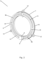
- Fig. 2 is a perspective view of a ring 5 according to an embodiment of the invention.
- the ring 5 is configured to form part of a stack of rings to be mounted in an inlet channel of a plate kind heat exchanger according to an embodiment of the invention.
- the ring 5 comprises a first rigid shell member 6, a second rigid shell member 7 and a sealing member 8 positioned between the first rigid shell member 6 and the second rigid shell member 7.
- the sealing member 8 is formed from a compressible material, whereas the rigid shell members 6, 7 are formed from an essentially non-compressible material.
- the first rigid shell member 6 and the second rigid shell member 7 are each provided with a groove 9 which provides fluid passage between an inner circumference of the ring 5 and an outer circumference of the ring 5. Accordingly, fluid passage is provided from the interior of the ring 5, forming an inner lining of the inlet channel, towards selected flow paths, via the grooves 9. Since the grooves 9 are formed in the rigid shell parts 6, 7, their size and shape are maintained when the rigid shell parts 6, 7 are pushed towards each other and the sealing member 8 is compressed. This ensures a well defined fluid flow from the inlet channel towards the flow paths.
- the first rigid shell member 6 is provided with two cut-outs 10, each allowing a portion 8a of the sealing member 8 to protrude through the first rigid shell member 6.
- the first rigid shell member 6 is further provided with two recesses 11, each forming a protruding part towards the sealing member 8. These protruding parts push portions of the sealing member 8 through cut-outs formed in the second rigid shell part 7, similar to the portions 8a protruding through the cut-outs 10 formed in the first rigid shell member 6. Furthermore, the recesses 11 are arranged to receive protruding parts of a sealing member of an adjacent ring.
- the sealing member 8 is provided with three protruding parts 12, each protruding from the sealing member 8 in a radial direction.
- the protruding parts 12 are configured to be arranged in engagement with corresponding recesses formed in a plate forming part of a stack of plates of a plate kind heat exchanger.
- the ring 5 is prevented from performing rotating movements relative to the plate.
- the grooves 9 remain in a fixed position relative to inlets of the relevant flow paths, and an accurate fluid flow towards the flow paths is ensured.
- Fig. 3 is an exploded view of the ring 5 of Fig. 2 .
- first rigid shell member 6, the second rigid shell member 7 and the sealing member 8 are clearly visible.
- first rigid shell member 6 and the second rigid shell member 7 are identical, the second rigid shell member 7 being rotated 180° relative to the first rigid shell member 7, thereby positioning the cut-outs 10 of the second rigid shell member 7 overlappingly with the recesses 11 of the first rigid shell member 6, and vice versa. It can further be seen that the recesses 11 result in protruding parts 13 of the second rigid shell member, and that these will push the portions 8a of the sealing member 8 through the cut-outs 10 of the first rigid shell member 6 when the ring 5 is assembled.
- protruding portions 8a are formed on the sealing member 8, and that corresponding recesses 14 arranged to receive protruding parts 13 of the rigid shell members 6, 7 are formed on sealing member 8, at positions corresponding to the protruding portions 8a, but on an opposite side of the sealing member 8.
- Fig. 4 is a perspective view of a stack of rings 15 comprising five rings 5 of the kind illustrated in Figs. 2 and 3 .
- each ring 5 comprises a first rigid shell member 6, a second rigid shell member 7 and a sealing member 8 arranged there between.
- the rings 5 are positioned adjacent to each other, thereby forming the stack of rings 15, in such a manner that a first rigid shell member 6 of one ring 5 is arranged in abutment with a second rigid shell member 7 of an adjacent ring 5.
- the grooves 9 formed in the rigid shell members 6, 7 provide fluid passages towards flow paths of a first set of flow paths.
- a compressing force is applied to the stack of rings 15 along an axial direction, thereby pushing the rigid shell members 6, 7 towards each other and compressing the sealing members 8, in the manner described above.
- sealing is provided between the first rigid shell member 6 and the second rigid shell member 7 of each ring 5, but also between the rings 5, due to the protruding portions 8a of the sealing members 8 abutting against rigid shell members 6, 7 of adjacent rings 5.
- sealing towards flow paths of a second set of flow paths is obtained.
- the stack of rings 15 is maintained in this compressed state, thereby maintaining the sealing towards the flow paths of the second set of flow paths.
- Part of a plate 2 of a plate kind heat exchanger having the stack of rings 15 mounted therein is shown, and it can be seen that the protruding parts 12 formed on the sealing member 8 of one of the rings 5 is arranged in engagement with corresponding recesses 16 formed in the plate 2. Thereby the stack of rings 15 is prevented from rotating relative to the plates 2 of the plate kind heat exchanger, and the grooves 9 remain firmly in fluid contact with inlets of the flow paths of the first set of flow paths.
- Fig. 5 is a perspective cross sectional view of the stack of rings 15 of Fig. 4 . It can clearly be seen that the protruding parts 13 of the rigid shell members 6, 7 push the protruding portions 8a of the sealing members 8 through cut-outs 10 formed in other rigid shell members 6, 7.
- Fig. 6 illustrates assembly of a stack of rings 15 according to an embodiment of the invention.
- the rings 5 are of the kind illustrated in Figs. 2-5 , i.e. each ring 5 comprises a first rigid shell member 6, a second rigid shell member 7 and a sealing member 8 arranged there between.
- the rings 5 are arranged adjacent to each other, in such a manner that protruding portions 8a of the sealing members 8 are received in recesses 11 formed in the second rigid shell members 7 of adjacent rings 5. Furthermore, protruding parts 13 of the second rigid shell members 7 are received in recesses 14 formed in the sealing members 8, and push the protruding portions 8a through cut-outs 10 in the first rigid shell members 6 and into abutment with the recesses 11 of the second rigid shell members 7 of the adjacent rings 5. Pushing the rings 5 towards each other causes the sealing members 8 to compress, thereby providing sealing in the manner described above with reference to Figs. 2-5 .
- the first rigid shell member 6 and the second rigid shell member 7 are arranged with a small gap there between. This allows the rigid shell members 6, 7 to be moved towards each other, while compressing the sealing member 8 arranged there between, when the stack of rings is subjected to a compressing force during assembly, as described above.
Landscapes
- Engineering & Computer Science (AREA)
- Physics & Mathematics (AREA)
- Thermal Sciences (AREA)
- Mechanical Engineering (AREA)
- General Engineering & Computer Science (AREA)
- Heat-Exchange Devices With Radiators And Conduit Assemblies (AREA)
Claims (16)
- Ring (5) für einen Plattenwärmetauscher (1), wobei der Ring (5) Folgendes umfasst:- ein erstes starres Schalenelement (6) und ein zweites starres Schalenelement (7), wobei das erste starre Schalenelement (6) und/oder das zweite starre Schalenelement (7) eine Nut (9) definieren, die einen Fluiddurchlass bereitstellt,- ein Dichtungselement (8), das aus einem komprimierbaren Material gebildet ist, wobei das Dichtungselement (8) zwischen dem ersten starren Schalenelement (6) und dem zweiten starren Schalenelement (7) positioniert ist, wodurch eine Abdichtung bereitgestellt ist.
- Ring (5) nach Anspruch 1, wobei das erste starre Schalenelement (6) und/oder das zweite starre Schalenelement (7) mit einem oder mehreren Ausschnitten (10) versehen ist/sind, die ermöglichen, dass ein Abschnitt (8a) des Dichtungselements (8) durch das starre Schalenelement (6, 7) hervorsteht, wodurch ermöglicht wird, dass das Dichtungselement (8) in abdichtendem Anlagekontakt mit einem starren Schalenelement (6, 7) eines angrenzenden Rings (5) angeordnet ist.
- Ring (5) nach Anspruch 2, wobei das erste starre Schalenelement (6) und/oder das zweite starre Schalenelement (7) mit einem oder mehreren hervorstehenden Teilen (13) versehen ist/sind, die derart angeordnet sind, dass sie den Abschnitt (8a) des Dichtungselements (8) durch einen in dem zweiten/ersten starren Schalenelement (7, 6) gebildeten Ausschnitt (10) drücken.
- Ring (5) nach einem der vorhergehenden Ansprüche, wobei das erste starren Schalenelement (6) identisch zu dem zweiten starren Schalenelement (7) ist.
- Ring (5) nach einem der vorhergehenden Ansprüche, wobei das Dichtungselement (8) mit hervorstehenden Teilen (12) versehen ist, die dazu ausgelegt sind, in Eingriff mit entsprechenden in einer Platte (2) des Plattenwärmetauschers (1) gebildeten Vertiefungen (16) angeordnet zu sein.
- Plattenwärmetauscher (1), der eine Mehrzahl von gestapelten Platten (2) umfasst, die Strömungswege für Wärmeaustauschfluide dazwischen bilden, wobei der Plattenwärmetauscher (1) einen ersten Einlasskanal, der strömungstechnisch mit Einlässen eines ersten Satzes von Strömungswegen verbunden ist, einen zweiten Einlasskanal, der strömungstechnisch mit Einlässen eines zweiten Satzes von Strömungswegen verbunden ist, einen ersten Auslasskanal, der strömungstechnisch mit Auslässen des ersten Satzes von Strömungswegen verbunden ist, und einen zweiten Auslasskanal, der strömungstechnisch mit Auslässen des zweiten Satzes von Strömungswegen verbunden ist, umfasst, wobei der erste Einlasskanal mit einem Stapel (15) aus Ringen (5) versehen ist, die Fluiddurchlässe hin zu den Einlässen des ersten Satzes von Strömungswegen bilden, wobei jeder Ring (5) ein Ring (5) nach einem der vorhergehenden Ansprüche ist,
wobei der Stapel aus Ringen (15) einer Kraft ausgesetzt ist, die die Ringe (5) zueinander hin drückt und die Dichtungselemente (8) der Ringe (5) komprimiert, wodurch eine Abdichtung hin zu den Strömungswegen des zweiten Satzes von Strömungswegen bereitgestellt wird. - Plattenwärmetauscher (1) nach Anspruch 6, wobei die ersten starren Schalenelemente (6) und/oder die zweiten starren Schalenelemente (7) der Ringe (5) mit einem oder mehreren Ausschnitten (10) versehen sind, die ermöglichen, dass ein Abschnitt (8a) des jeweiligen Dichtungselements (8) durch das starre Schalenelement (6, 7) hervorsteht, wodurch das Dichtungselement (8) in abdichtendem Anlagekontakt mit einem starren Schalenelement (6, 7) eines angrenzenden Rings (5) positioniert ist.
- Plattenwärmetauscher (1) nach Anspruch 7, wobei die ersten starren Schalenelemente (6) und/oder die zweiten starren Schalenelemente (7) mit einem oder mehreren hervorstehenden Teilen (13) versehen sind, die derart angeordnet sind, dass sie den Abschnitt (8a) des jeweiligen Dichtungselements (8) durch einen in einem entsprechenden zweiten/ersten starren Schalenelement (7, 6) gebildeten Ausschnitt (10) drücken.
- Plattenwärmetauscher (1) nach einem der Ansprüche 6-8, wobei das erste starre Schalenelement (6) identisch zu dem zweiten starren Schalenelement (7) ist.
- Plattenwärmetauscher (1) nach einem der Ansprüche 6-9, wobei die Dichtungselemente (8) mit hervorstehenden Teilen (12) versehen sind, die in Eingriff mit entsprechenden in den gestapelten Platten (2) gebildeten Vertiefungen (16) angeordnet sind, wodurch jeder Ring (5) relativ zu einer Platte (2) fixiert wird.
- Plattenwärmetauscher (1) nach einem der Ansprüche 6-10, wobei die ersten starren Schalenelemente (6) und die zweiten starren Schalenelemente (7) aus demselben Material wie die gestapelten Platten (2) bestehen.
- Plattenwärmetauscher (1) nach einem der Ansprüche 6-11, wobei der erste Einlasskanal mit einer Fluidzufuhr eines Fluid verbindbar ist, das die Kaltseite des Plattenwärmetauschers (1) bildet.
- Plattenwärmetauscher (1) nach einem der Ansprüche 6-12, wobei der Plattenwärmetauscher (1) ein Verdampfer ist oder einen Teil davon bildet.
- Verfahren zum Herstellen eines Plattenwärmetauschers (1) nach einem der Ansprüche 6-13, wobei das Verfahren die folgenden Schritte umfasst:- Bereitstellen einer Mehrzahl von Platten (2),- Bilden einer Mehrzahl von Ringen (5) durch, für jeden Ring (5):- Bereitstellen eines ersten starren Schalenelements (6), eines zweiten starren Schalenelements (7) und eines Dichtungselements (8) aus einem komprimierbaren Material, wobei das erste starre Schalenelement (6) und/oder das zweite starre Schalenelement (7) eine Nut (9) definiert, und- Anordnen des Dichtungselements (8) zwischen dem ersten starren Schalenelement (6) und dem zweiten starren Schalenelement (7),- Bilden eines Stapels aus der Mehrzahl von Platten (2), wodurch Strömungswege zwischen den Platten (2) gebildet werden, und Bilden eines Stapels (15) aus der Mehrzahl von Ringen (5), wobei der Stapel aus Ringen (15) in einem in dem Stapel aus Platten (2) gebildeten Einlasskanal angeordnet wird, und- Drücken der Ringe (5) zueinander hin, wodurch die Dichtungselemente (8) komprimiert werden und eine Abdichtung hin zu einem zwischen den Platten (2) gebildeten zweiten Satz von Strömungswegen bereitgestellt wird.
- Verfahren nach Anspruch 14, wobei der Schritt zum Bereitstellen einer Mehrzahl von Platten (2) für jede Platte (2) Stanzen eines oder mehrerer Durchgangslöcher (4) in die Platte (2) umfasst, wobei die Durchgangslöcher (4) in den Platten (2) Einlasskanäle und/oder Auslasskanäle des Plattenwärmetauschers (1) bilden, wenn die Platten (2) gestapelt werden, und wobei der Schritt zum Bereitstellen eines ersten starren Schalenelements (6) und/oder der Schritt zum Bereitstellen eines zweiten starren Schalenelements (7) als Teil des Stanzens des einen oder der mehreren Durchgangslöcher (4) in die Platten (2) durchgeführt wird/werden.
- Verfahren nach Anspruch 14 oder 15, ferner umfassend den Schritt Zurückhalten des Stapels aus Ringen (15) nach Komprimieren der Dichtungselemente (8), wodurch die Dichtungselemente (8) in einem komprimierten Zustand gehalten werden und die Abdichtung hin zu dem zweiten Satz von Strömungswegen aufrechterhalten wird.
Applications Claiming Priority (1)
| Application Number | Priority Date | Filing Date | Title |
|---|---|---|---|
| DKPA202100562 | 2021-05-27 |
Publications (2)
| Publication Number | Publication Date |
|---|---|
| EP4095472A1 EP4095472A1 (de) | 2022-11-30 |
| EP4095472B1 true EP4095472B1 (de) | 2025-01-01 |
Family
ID=81328151
Family Applications (1)
| Application Number | Title | Priority Date | Filing Date |
|---|---|---|---|
| EP22166465.9A Active EP4095472B1 (de) | 2021-05-27 | 2022-04-04 | Plattenwärmetauscher mit abgedichtetem einlasskanal |
Country Status (3)
| Country | Link |
|---|---|
| US (2) | US11982496B2 (de) |
| EP (1) | EP4095472B1 (de) |
| CN (1) | CN115406274A (de) |
Families Citing this family (1)
| Publication number | Priority date | Publication date | Assignee | Title |
|---|---|---|---|---|
| EP4095472B1 (de) * | 2021-05-27 | 2025-01-01 | Danfoss A/S | Plattenwärmetauscher mit abgedichtetem einlasskanal |
Family Cites Families (9)
| Publication number | Priority date | Publication date | Assignee | Title |
|---|---|---|---|---|
| DE4303669C1 (de) * | 1993-02-09 | 1994-01-20 | Kyffhaeuser Maschf Artern Gmbh | Wärmeübertragungsplatte |
| AT4708U1 (de) * | 2000-11-15 | 2001-10-25 | Hermeling Werner Dipl Ing | Axial durchströmtes hochdruckschieberventil |
| SE531241C2 (sv) | 2005-04-13 | 2009-01-27 | Alfa Laval Corp Ab | Plattvärmeväxlare med huvudsakligen jämn cylindrisk inloppskanal |
| US10012444B2 (en) * | 2012-03-21 | 2018-07-03 | Energy Wall | Multiple opening counter-flow plate exchanger and method of making |
| DK2730878T3 (da) * | 2012-11-07 | 2019-06-11 | Alfa Laval Corp Ab | Pladestak og fremgangsmåde til fremstilling af en pladestak |
| CN103759474B (zh) * | 2014-01-28 | 2018-01-02 | 丹佛斯微通道换热器(嘉兴)有限公司 | 板式换热器 |
| SE541284C2 (en) * | 2016-05-30 | 2019-06-11 | Alfa Laval Corp Ab | A plate heat exchanger |
| DE102018203450B4 (de) * | 2018-03-07 | 2020-04-02 | Continental Automotive Gmbh | Dichtungsanordnung, Fluidregelventil mit einer solchen Dichtungsanordnung und Verwendung eines solchen Fluidregelventils |
| EP4095472B1 (de) * | 2021-05-27 | 2025-01-01 | Danfoss A/S | Plattenwärmetauscher mit abgedichtetem einlasskanal |
-
2022
- 2022-04-04 EP EP22166465.9A patent/EP4095472B1/de active Active
- 2022-05-09 CN CN202210501133.1A patent/CN115406274A/zh active Pending
- 2022-05-25 US US17/752,929 patent/US11982496B2/en active Active
-
2024
- 2024-03-05 US US18/595,562 patent/US20240210117A1/en not_active Abandoned
Also Published As
| Publication number | Publication date |
|---|---|
| EP4095472A1 (de) | 2022-11-30 |
| CN115406274A (zh) | 2022-11-29 |
| US20220381518A1 (en) | 2022-12-01 |
| US20240210117A1 (en) | 2024-06-27 |
| US11982496B2 (en) | 2024-05-14 |
Similar Documents
| Publication | Publication Date | Title |
|---|---|---|
| EP1869391B1 (de) | Plattenwärmetauscher | |
| US6164371A (en) | Plate heat exchanger for three heat exchanging fluids | |
| EP0857287B1 (de) | Plattenwärmetauscher | |
| US4431050A (en) | Stacked-plate heat exchanger made of identical corrugated plates | |
| KR20060132645A (ko) | 브레이징 플레이트형 열 교환기 | |
| JP4262779B2 (ja) | 熱伝達プレートの製造方法と熱伝達プレートの組立体及び熱伝達プレートの組立体からなるプレート熱交換器 | |
| PL182464B1 (pl) | Sposób wytwarzania wymiennika ciepła i wymiennik ciepła | |
| US20240210117A1 (en) | Plate kind heat exchanger with sealed inlet channel | |
| EP3458789B1 (de) | Doppelrohr für einen wärmetauscher | |
| EP1702193B1 (de) | Plattenwärmetauscher | |
| JP2980631B2 (ja) | 積層型熱交換器 | |
| JP2006125652A (ja) | 熱交換器 | |
| EP1405023B1 (de) | Wärmeübertragungsplatte, plattenpaket und plattenwärmetauscher | |
| EP4036507B1 (de) | Plattenrippenwärmetauscher und kälteanlage damit | |
| AU755895B2 (en) | Radial flow annular heat exchangers | |
| EP0956488B1 (de) | Plattenwärmetauscher | |
| JP7721417B2 (ja) | 熱交換器用のプレート積層体ユニットの製造方法 | |
| JP2741950B2 (ja) | 積層式熱交換器 | |
| EP4464971A1 (de) | Wärmetauscher | |
| JPH08145503A (ja) | 熱交換器 | |
| EP1229294B1 (de) | Plattenwärmetauscher | |
| WO2025008233A1 (en) | Plate heat exchanger and heat pump circuit | |
| KR20250070812A (ko) | 차량용 열교환 모듈 및 차량용 열교환 모듈의 매니폴드 플레이트 | |
| CN114877724A (zh) | 一种换热装置 | |
| HK1117223B (en) | Tube inset and bi-flow arrangement for a header of a heat pump |
Legal Events
| Date | Code | Title | Description |
|---|---|---|---|
| PUAI | Public reference made under article 153(3) epc to a published international application that has entered the european phase |
Free format text: ORIGINAL CODE: 0009012 |
|
| STAA | Information on the status of an ep patent application or granted ep patent |
Free format text: STATUS: THE APPLICATION HAS BEEN PUBLISHED |
|
| AK | Designated contracting states |
Kind code of ref document: A1 Designated state(s): AL AT BE BG CH CY CZ DE DK EE ES FI FR GB GR HR HU IE IS IT LI LT LU LV MC MK MT NL NO PL PT RO RS SE SI SK SM TR |
|
| STAA | Information on the status of an ep patent application or granted ep patent |
Free format text: STATUS: REQUEST FOR EXAMINATION WAS MADE |
|
| 17P | Request for examination filed |
Effective date: 20230324 |
|
| RBV | Designated contracting states (corrected) |
Designated state(s): AL AT BE BG CH CY CZ DE DK EE ES FI FR GB GR HR HU IE IS IT LI LT LU LV MC MK MT NL NO PL PT RO RS SE SI SK SM TR |
|
| P01 | Opt-out of the competence of the unified patent court (upc) registered |
Effective date: 20230713 |
|
| STAA | Information on the status of an ep patent application or granted ep patent |
Free format text: STATUS: EXAMINATION IS IN PROGRESS |
|
| 17Q | First examination report despatched |
Effective date: 20240514 |
|
| GRAP | Despatch of communication of intention to grant a patent |
Free format text: ORIGINAL CODE: EPIDOSNIGR1 |
|
| STAA | Information on the status of an ep patent application or granted ep patent |
Free format text: STATUS: GRANT OF PATENT IS INTENDED |
|
| INTG | Intention to grant announced |
Effective date: 20240920 |
|
| GRAS | Grant fee paid |
Free format text: ORIGINAL CODE: EPIDOSNIGR3 |
|
| GRAA | (expected) grant |
Free format text: ORIGINAL CODE: 0009210 |
|
| STAA | Information on the status of an ep patent application or granted ep patent |
Free format text: STATUS: THE PATENT HAS BEEN GRANTED |
|
| AK | Designated contracting states |
Kind code of ref document: B1 Designated state(s): AL AT BE BG CH CY CZ DE DK EE ES FI FR GB GR HR HU IE IS IT LI LT LU LV MC MK MT NL NO PL PT RO RS SE SI SK SM TR |
|
| REG | Reference to a national code |
Ref country code: GB Ref legal event code: FG4D |
|
| REG | Reference to a national code |
Ref country code: CH Ref legal event code: EP |
|
| REG | Reference to a national code |
Ref country code: DE Ref legal event code: R096 Ref document number: 602022009228 Country of ref document: DE |
|
| REG | Reference to a national code |
Ref country code: IE Ref legal event code: FG4D |
|
| REG | Reference to a national code |
Ref country code: LT Ref legal event code: MG9D |
|
| REG | Reference to a national code |
Ref country code: NL Ref legal event code: MP Effective date: 20250101 |
|
| REG | Reference to a national code |
Ref country code: AT Ref legal event code: MK05 Ref document number: 1756632 Country of ref document: AT Kind code of ref document: T Effective date: 20250101 |
|
| PG25 | Lapsed in a contracting state [announced via postgrant information from national office to epo] |
Ref country code: NL Free format text: LAPSE BECAUSE OF FAILURE TO SUBMIT A TRANSLATION OF THE DESCRIPTION OR TO PAY THE FEE WITHIN THE PRESCRIBED TIME-LIMIT Effective date: 20250101 |
|
| PG25 | Lapsed in a contracting state [announced via postgrant information from national office to epo] |
Ref country code: FI Free format text: LAPSE BECAUSE OF FAILURE TO SUBMIT A TRANSLATION OF THE DESCRIPTION OR TO PAY THE FEE WITHIN THE PRESCRIBED TIME-LIMIT Effective date: 20250101 |
|
| PG25 | Lapsed in a contracting state [announced via postgrant information from national office to epo] |
Ref country code: PL Free format text: LAPSE BECAUSE OF FAILURE TO SUBMIT A TRANSLATION OF THE DESCRIPTION OR TO PAY THE FEE WITHIN THE PRESCRIBED TIME-LIMIT Effective date: 20250101 |
|
| PG25 | Lapsed in a contracting state [announced via postgrant information from national office to epo] |
Ref country code: ES Free format text: LAPSE BECAUSE OF FAILURE TO SUBMIT A TRANSLATION OF THE DESCRIPTION OR TO PAY THE FEE WITHIN THE PRESCRIBED TIME-LIMIT Effective date: 20250101 |
|
| PG25 | Lapsed in a contracting state [announced via postgrant information from national office to epo] |
Ref country code: NO Free format text: LAPSE BECAUSE OF FAILURE TO SUBMIT A TRANSLATION OF THE DESCRIPTION OR TO PAY THE FEE WITHIN THE PRESCRIBED TIME-LIMIT Effective date: 20250401 Ref country code: IS Free format text: LAPSE BECAUSE OF FAILURE TO SUBMIT A TRANSLATION OF THE DESCRIPTION OR TO PAY THE FEE WITHIN THE PRESCRIBED TIME-LIMIT Effective date: 20250501 |
|
| PG25 | Lapsed in a contracting state [announced via postgrant information from national office to epo] |
Ref country code: HR Free format text: LAPSE BECAUSE OF FAILURE TO SUBMIT A TRANSLATION OF THE DESCRIPTION OR TO PAY THE FEE WITHIN THE PRESCRIBED TIME-LIMIT Effective date: 20250101 |
|
| PG25 | Lapsed in a contracting state [announced via postgrant information from national office to epo] |
Ref country code: LV Free format text: LAPSE BECAUSE OF FAILURE TO SUBMIT A TRANSLATION OF THE DESCRIPTION OR TO PAY THE FEE WITHIN THE PRESCRIBED TIME-LIMIT Effective date: 20250101 Ref country code: PT Free format text: LAPSE BECAUSE OF FAILURE TO SUBMIT A TRANSLATION OF THE DESCRIPTION OR TO PAY THE FEE WITHIN THE PRESCRIBED TIME-LIMIT Effective date: 20250502 |
|
| PG25 | Lapsed in a contracting state [announced via postgrant information from national office to epo] |
Ref country code: BG Free format text: LAPSE BECAUSE OF FAILURE TO SUBMIT A TRANSLATION OF THE DESCRIPTION OR TO PAY THE FEE WITHIN THE PRESCRIBED TIME-LIMIT Effective date: 20250101 Ref country code: GR Free format text: LAPSE BECAUSE OF FAILURE TO SUBMIT A TRANSLATION OF THE DESCRIPTION OR TO PAY THE FEE WITHIN THE PRESCRIBED TIME-LIMIT Effective date: 20250402 |
|
| PG25 | Lapsed in a contracting state [announced via postgrant information from national office to epo] |
Ref country code: AT Free format text: LAPSE BECAUSE OF FAILURE TO SUBMIT A TRANSLATION OF THE DESCRIPTION OR TO PAY THE FEE WITHIN THE PRESCRIBED TIME-LIMIT Effective date: 20250101 |
|
| PG25 | Lapsed in a contracting state [announced via postgrant information from national office to epo] |
Ref country code: CZ Free format text: LAPSE BECAUSE OF FAILURE TO SUBMIT A TRANSLATION OF THE DESCRIPTION OR TO PAY THE FEE WITHIN THE PRESCRIBED TIME-LIMIT Effective date: 20250101 |
|
| PG25 | Lapsed in a contracting state [announced via postgrant information from national office to epo] |
Ref country code: SE Free format text: LAPSE BECAUSE OF FAILURE TO SUBMIT A TRANSLATION OF THE DESCRIPTION OR TO PAY THE FEE WITHIN THE PRESCRIBED TIME-LIMIT Effective date: 20250101 |
|
| REG | Reference to a national code |
Ref country code: DE Ref legal event code: R097 Ref document number: 602022009228 Country of ref document: DE |
|
| PG25 | Lapsed in a contracting state [announced via postgrant information from national office to epo] |
Ref country code: SM Free format text: LAPSE BECAUSE OF FAILURE TO SUBMIT A TRANSLATION OF THE DESCRIPTION OR TO PAY THE FEE WITHIN THE PRESCRIBED TIME-LIMIT Effective date: 20250101 |
|
| PG25 | Lapsed in a contracting state [announced via postgrant information from national office to epo] |
Ref country code: DK Free format text: LAPSE BECAUSE OF FAILURE TO SUBMIT A TRANSLATION OF THE DESCRIPTION OR TO PAY THE FEE WITHIN THE PRESCRIBED TIME-LIMIT Effective date: 20250101 |
|
| PG25 | Lapsed in a contracting state [announced via postgrant information from national office to epo] |
Ref country code: IT Free format text: LAPSE BECAUSE OF FAILURE TO SUBMIT A TRANSLATION OF THE DESCRIPTION OR TO PAY THE FEE WITHIN THE PRESCRIBED TIME-LIMIT Effective date: 20250101 |
|
| PG25 | Lapsed in a contracting state [announced via postgrant information from national office to epo] |
Ref country code: EE Free format text: LAPSE BECAUSE OF FAILURE TO SUBMIT A TRANSLATION OF THE DESCRIPTION OR TO PAY THE FEE WITHIN THE PRESCRIBED TIME-LIMIT Effective date: 20250101 |
|
| PG25 | Lapsed in a contracting state [announced via postgrant information from national office to epo] |
Ref country code: RO Free format text: LAPSE BECAUSE OF FAILURE TO SUBMIT A TRANSLATION OF THE DESCRIPTION OR TO PAY THE FEE WITHIN THE PRESCRIBED TIME-LIMIT Effective date: 20250101 |
|
| PG25 | Lapsed in a contracting state [announced via postgrant information from national office to epo] |
Ref country code: SK Free format text: LAPSE BECAUSE OF FAILURE TO SUBMIT A TRANSLATION OF THE DESCRIPTION OR TO PAY THE FEE WITHIN THE PRESCRIBED TIME-LIMIT Effective date: 20250101 |
|
| REG | Reference to a national code |
Ref country code: DE Ref legal event code: R119 Ref document number: 602022009228 Country of ref document: DE |
|
| PLBE | No opposition filed within time limit |
Free format text: ORIGINAL CODE: 0009261 |
|
| STAA | Information on the status of an ep patent application or granted ep patent |
Free format text: STATUS: NO OPPOSITION FILED WITHIN TIME LIMIT |
|
| REG | Reference to a national code |
Ref country code: CH Ref legal event code: L10 Free format text: ST27 STATUS EVENT CODE: U-0-0-L10-L00 (AS PROVIDED BY THE NATIONAL OFFICE) Effective date: 20251112 |
|
| REG | Reference to a national code |
Ref country code: CH Ref legal event code: H13 Free format text: ST27 STATUS EVENT CODE: U-0-0-H10-H13 (AS PROVIDED BY THE NATIONAL OFFICE) Effective date: 20251125 |
|
| 26N | No opposition filed |
Effective date: 20251002 |
|
| PG25 | Lapsed in a contracting state [announced via postgrant information from national office to epo] |
Ref country code: LU Free format text: LAPSE BECAUSE OF NON-PAYMENT OF DUE FEES Effective date: 20250404 |
|
| PG25 | Lapsed in a contracting state [announced via postgrant information from national office to epo] |
Ref country code: MC Free format text: LAPSE BECAUSE OF FAILURE TO SUBMIT A TRANSLATION OF THE DESCRIPTION OR TO PAY THE FEE WITHIN THE PRESCRIBED TIME-LIMIT Effective date: 20250101 |
|
| REG | Reference to a national code |
Ref country code: BE Ref legal event code: MM Effective date: 20250430 |
|
| PG25 | Lapsed in a contracting state [announced via postgrant information from national office to epo] |
Ref country code: DE Free format text: LAPSE BECAUSE OF NON-PAYMENT OF DUE FEES Effective date: 20251104 |
|
| PG25 | Lapsed in a contracting state [announced via postgrant information from national office to epo] |
Ref country code: FR Free format text: LAPSE BECAUSE OF NON-PAYMENT OF DUE FEES Effective date: 20250430 |
|
| PG25 | Lapsed in a contracting state [announced via postgrant information from national office to epo] |
Ref country code: BE Free format text: LAPSE BECAUSE OF NON-PAYMENT OF DUE FEES Effective date: 20250430 |
|
| PG25 | Lapsed in a contracting state [announced via postgrant information from national office to epo] |
Ref country code: CH Free format text: LAPSE BECAUSE OF NON-PAYMENT OF DUE FEES Effective date: 20250430 |