EP4095288A1 - Verfahren zum beschichten eines bauteils - Google Patents
Verfahren zum beschichten eines bauteils Download PDFInfo
- Publication number
- EP4095288A1 EP4095288A1 EP22173657.2A EP22173657A EP4095288A1 EP 4095288 A1 EP4095288 A1 EP 4095288A1 EP 22173657 A EP22173657 A EP 22173657A EP 4095288 A1 EP4095288 A1 EP 4095288A1
- Authority
- EP
- European Patent Office
- Prior art keywords
- coating
- component
- blade
- edge
- turbomachine
- Prior art date
- Legal status (The legal status is an assumption and is not a legal conclusion. Google has not performed a legal analysis and makes no representation as to the accuracy of the status listed.)
- Pending
Links
- 239000011248 coating agent Substances 0.000 title claims abstract description 48
- 238000000576 coating method Methods 0.000 title claims abstract description 48
- 238000000034 method Methods 0.000 title claims abstract description 27
- 229910052582 BN Inorganic materials 0.000 claims description 5
- PZNSFCLAULLKQX-UHFFFAOYSA-N Boron nitride Chemical compound N#B PZNSFCLAULLKQX-UHFFFAOYSA-N 0.000 claims description 5
- 238000000227 grinding Methods 0.000 claims description 5
- 238000004519 manufacturing process Methods 0.000 claims description 2
- 239000000463 material Substances 0.000 description 9
- PXHVJJICTQNCMI-UHFFFAOYSA-N Nickel Chemical compound [Ni] PXHVJJICTQNCMI-UHFFFAOYSA-N 0.000 description 5
- 238000002485 combustion reaction Methods 0.000 description 5
- 239000002245 particle Substances 0.000 description 5
- 230000005284 excitation Effects 0.000 description 3
- 239000007789 gas Substances 0.000 description 3
- 230000001680 brushing effect Effects 0.000 description 2
- 238000005336 cracking Methods 0.000 description 2
- 230000005684 electric field Effects 0.000 description 2
- 238000004070 electrodeposition Methods 0.000 description 2
- 230000000977 initiatory effect Effects 0.000 description 2
- 239000003350 kerosene Substances 0.000 description 2
- 239000011159 matrix material Substances 0.000 description 2
- 239000002184 metal Substances 0.000 description 2
- 229910052751 metal Inorganic materials 0.000 description 2
- 229910052759 nickel Inorganic materials 0.000 description 2
- 238000012545 processing Methods 0.000 description 2
- 238000009825 accumulation Methods 0.000 description 1
- 239000000567 combustion gas Substances 0.000 description 1
- 230000000052 comparative effect Effects 0.000 description 1
- 239000013078 crystal Substances 0.000 description 1
- 230000001419 dependent effect Effects 0.000 description 1
- 238000000151 deposition Methods 0.000 description 1
- 230000008021 deposition Effects 0.000 description 1
- 238000005137 deposition process Methods 0.000 description 1
- 238000011161 development Methods 0.000 description 1
- 229910003460 diamond Inorganic materials 0.000 description 1
- 239000010432 diamond Substances 0.000 description 1
- 238000009661 fatigue test Methods 0.000 description 1
- 238000007730 finishing process Methods 0.000 description 1
- 238000010348 incorporation Methods 0.000 description 1
- 150000001247 metal acetylides Chemical class 0.000 description 1
- 229910021645 metal ion Inorganic materials 0.000 description 1
- 239000000203 mixture Substances 0.000 description 1
- 230000010355 oscillation Effects 0.000 description 1
- 238000007747 plating Methods 0.000 description 1
- 239000011253 protective coating Substances 0.000 description 1
- 238000005476 soldering Methods 0.000 description 1
- 239000000126 substance Substances 0.000 description 1
Images


Classifications
-
- C—CHEMISTRY; METALLURGY
- C25—ELECTROLYTIC OR ELECTROPHORETIC PROCESSES; APPARATUS THEREFOR
- C25D—PROCESSES FOR THE ELECTROLYTIC OR ELECTROPHORETIC PRODUCTION OF COATINGS; ELECTROFORMING; APPARATUS THEREFOR
- C25D5/00—Electroplating characterised by the process; Pretreatment or after-treatment of workpieces
- C25D5/34—Pretreatment of metallic surfaces to be electroplated
-
- C—CHEMISTRY; METALLURGY
- C25—ELECTROLYTIC OR ELECTROPHORETIC PROCESSES; APPARATUS THEREFOR
- C25D—PROCESSES FOR THE ELECTROLYTIC OR ELECTROPHORETIC PRODUCTION OF COATINGS; ELECTROFORMING; APPARATUS THEREFOR
- C25D9/00—Electrolytic coating other than with metals
- C25D9/04—Electrolytic coating other than with metals with inorganic materials
- C25D9/08—Electrolytic coating other than with metals with inorganic materials by cathodic processes
-
- B—PERFORMING OPERATIONS; TRANSPORTING
- B23—MACHINE TOOLS; METAL-WORKING NOT OTHERWISE PROVIDED FOR
- B23P—METAL-WORKING NOT OTHERWISE PROVIDED FOR; COMBINED OPERATIONS; UNIVERSAL MACHINE TOOLS
- B23P15/00—Making specific metal objects by operations not covered by a single other subclass or a group in this subclass
- B23P15/02—Making specific metal objects by operations not covered by a single other subclass or a group in this subclass turbine or like blades from one piece
-
- C—CHEMISTRY; METALLURGY
- C25—ELECTROLYTIC OR ELECTROPHORETIC PROCESSES; APPARATUS THEREFOR
- C25D—PROCESSES FOR THE ELECTROLYTIC OR ELECTROPHORETIC PRODUCTION OF COATINGS; ELECTROFORMING; APPARATUS THEREFOR
- C25D15/00—Electrolytic or electrophoretic production of coatings containing embedded materials, e.g. particles, whiskers, wires
- C25D15/02—Combined electrolytic and electrophoretic processes with charged materials
-
- C—CHEMISTRY; METALLURGY
- C25—ELECTROLYTIC OR ELECTROPHORETIC PROCESSES; APPARATUS THEREFOR
- C25D—PROCESSES FOR THE ELECTROLYTIC OR ELECTROPHORETIC PRODUCTION OF COATINGS; ELECTROFORMING; APPARATUS THEREFOR
- C25D5/00—Electroplating characterised by the process; Pretreatment or after-treatment of workpieces
- C25D5/02—Electroplating of selected surface areas
-
- C—CHEMISTRY; METALLURGY
- C25—ELECTROLYTIC OR ELECTROPHORETIC PROCESSES; APPARATUS THEREFOR
- C25D—PROCESSES FOR THE ELECTROLYTIC OR ELECTROPHORETIC PRODUCTION OF COATINGS; ELECTROFORMING; APPARATUS THEREFOR
- C25D7/00—Electroplating characterised by the article coated
-
- F—MECHANICAL ENGINEERING; LIGHTING; HEATING; WEAPONS; BLASTING
- F01—MACHINES OR ENGINES IN GENERAL; ENGINE PLANTS IN GENERAL; STEAM ENGINES
- F01D—NON-POSITIVE DISPLACEMENT MACHINES OR ENGINES, e.g. STEAM TURBINES
- F01D5/00—Blades; Blade-carrying members; Heating, heat-insulating, cooling or antivibration means on the blades or the members
- F01D5/005—Repairing methods or devices
-
- F—MECHANICAL ENGINEERING; LIGHTING; HEATING; WEAPONS; BLASTING
- F01—MACHINES OR ENGINES IN GENERAL; ENGINE PLANTS IN GENERAL; STEAM ENGINES
- F01D—NON-POSITIVE DISPLACEMENT MACHINES OR ENGINES, e.g. STEAM TURBINES
- F01D5/00—Blades; Blade-carrying members; Heating, heat-insulating, cooling or antivibration means on the blades or the members
- F01D5/12—Blades
- F01D5/14—Form or construction
- F01D5/20—Specially-shaped blade tips to seal space between tips and stator
-
- F—MECHANICAL ENGINEERING; LIGHTING; HEATING; WEAPONS; BLASTING
- F01—MACHINES OR ENGINES IN GENERAL; ENGINE PLANTS IN GENERAL; STEAM ENGINES
- F01D—NON-POSITIVE DISPLACEMENT MACHINES OR ENGINES, e.g. STEAM TURBINES
- F01D5/00—Blades; Blade-carrying members; Heating, heat-insulating, cooling or antivibration means on the blades or the members
- F01D5/12—Blades
- F01D5/28—Selecting particular materials; Particular measures relating thereto; Measures against erosion or corrosion
- F01D5/288—Protective coatings for blades
-
- F—MECHANICAL ENGINEERING; LIGHTING; HEATING; WEAPONS; BLASTING
- F05—INDEXING SCHEMES RELATING TO ENGINES OR PUMPS IN VARIOUS SUBCLASSES OF CLASSES F01-F04
- F05D—INDEXING SCHEME FOR ASPECTS RELATING TO NON-POSITIVE-DISPLACEMENT MACHINES OR ENGINES, GAS-TURBINES OR JET-PROPULSION PLANTS
- F05D2230/00—Manufacture
- F05D2230/10—Manufacture by removing material
-
- F—MECHANICAL ENGINEERING; LIGHTING; HEATING; WEAPONS; BLASTING
- F05—INDEXING SCHEMES RELATING TO ENGINES OR PUMPS IN VARIOUS SUBCLASSES OF CLASSES F01-F04
- F05D—INDEXING SCHEME FOR ASPECTS RELATING TO NON-POSITIVE-DISPLACEMENT MACHINES OR ENGINES, GAS-TURBINES OR JET-PROPULSION PLANTS
- F05D2230/00—Manufacture
- F05D2230/10—Manufacture by removing material
- F05D2230/14—Micromachining
-
- F—MECHANICAL ENGINEERING; LIGHTING; HEATING; WEAPONS; BLASTING
- F05—INDEXING SCHEMES RELATING TO ENGINES OR PUMPS IN VARIOUS SUBCLASSES OF CLASSES F01-F04
- F05D—INDEXING SCHEME FOR ASPECTS RELATING TO NON-POSITIVE-DISPLACEMENT MACHINES OR ENGINES, GAS-TURBINES OR JET-PROPULSION PLANTS
- F05D2230/00—Manufacture
- F05D2230/30—Manufacture with deposition of material
- F05D2230/31—Layer deposition
-
- F—MECHANICAL ENGINEERING; LIGHTING; HEATING; WEAPONS; BLASTING
- F05—INDEXING SCHEMES RELATING TO ENGINES OR PUMPS IN VARIOUS SUBCLASSES OF CLASSES F01-F04
- F05D—INDEXING SCHEME FOR ASPECTS RELATING TO NON-POSITIVE-DISPLACEMENT MACHINES OR ENGINES, GAS-TURBINES OR JET-PROPULSION PLANTS
- F05D2230/00—Manufacture
- F05D2230/90—Coating; Surface treatment
-
- F—MECHANICAL ENGINEERING; LIGHTING; HEATING; WEAPONS; BLASTING
- F05—INDEXING SCHEMES RELATING TO ENGINES OR PUMPS IN VARIOUS SUBCLASSES OF CLASSES F01-F04
- F05D—INDEXING SCHEME FOR ASPECTS RELATING TO NON-POSITIVE-DISPLACEMENT MACHINES OR ENGINES, GAS-TURBINES OR JET-PROPULSION PLANTS
- F05D2240/00—Components
- F05D2240/20—Rotors
- F05D2240/30—Characteristics of rotor blades, i.e. of any element transforming dynamic fluid energy to or from rotational energy and being attached to a rotor
- F05D2240/307—Characteristics of rotor blades, i.e. of any element transforming dynamic fluid energy to or from rotational energy and being attached to a rotor related to the tip of a rotor blade
-
- F—MECHANICAL ENGINEERING; LIGHTING; HEATING; WEAPONS; BLASTING
- F05—INDEXING SCHEMES RELATING TO ENGINES OR PUMPS IN VARIOUS SUBCLASSES OF CLASSES F01-F04
- F05D—INDEXING SCHEME FOR ASPECTS RELATING TO NON-POSITIVE-DISPLACEMENT MACHINES OR ENGINES, GAS-TURBINES OR JET-PROPULSION PLANTS
- F05D2250/00—Geometry
- F05D2250/10—Two-dimensional
- F05D2250/14—Two-dimensional elliptical
-
- F—MECHANICAL ENGINEERING; LIGHTING; HEATING; WEAPONS; BLASTING
- F05—INDEXING SCHEMES RELATING TO ENGINES OR PUMPS IN VARIOUS SUBCLASSES OF CLASSES F01-F04
- F05D—INDEXING SCHEME FOR ASPECTS RELATING TO NON-POSITIVE-DISPLACEMENT MACHINES OR ENGINES, GAS-TURBINES OR JET-PROPULSION PLANTS
- F05D2250/00—Geometry
- F05D2250/10—Two-dimensional
- F05D2250/14—Two-dimensional elliptical
- F05D2250/141—Two-dimensional elliptical circular
-
- F—MECHANICAL ENGINEERING; LIGHTING; HEATING; WEAPONS; BLASTING
- F05—INDEXING SCHEMES RELATING TO ENGINES OR PUMPS IN VARIOUS SUBCLASSES OF CLASSES F01-F04
- F05D—INDEXING SCHEME FOR ASPECTS RELATING TO NON-POSITIVE-DISPLACEMENT MACHINES OR ENGINES, GAS-TURBINES OR JET-PROPULSION PLANTS
- F05D2250/00—Geometry
- F05D2250/20—Three-dimensional
- F05D2250/23—Three-dimensional prismatic
- F05D2250/231—Three-dimensional prismatic cylindrical
-
- F—MECHANICAL ENGINEERING; LIGHTING; HEATING; WEAPONS; BLASTING
- F05—INDEXING SCHEMES RELATING TO ENGINES OR PUMPS IN VARIOUS SUBCLASSES OF CLASSES F01-F04
- F05D—INDEXING SCHEME FOR ASPECTS RELATING TO NON-POSITIVE-DISPLACEMENT MACHINES OR ENGINES, GAS-TURBINES OR JET-PROPULSION PLANTS
- F05D2250/00—Geometry
- F05D2250/20—Three-dimensional
- F05D2250/29—Three-dimensional machined; miscellaneous
- F05D2250/292—Three-dimensional machined; miscellaneous tapered
-
- F—MECHANICAL ENGINEERING; LIGHTING; HEATING; WEAPONS; BLASTING
- F05—INDEXING SCHEMES RELATING TO ENGINES OR PUMPS IN VARIOUS SUBCLASSES OF CLASSES F01-F04
- F05D—INDEXING SCHEME FOR ASPECTS RELATING TO NON-POSITIVE-DISPLACEMENT MACHINES OR ENGINES, GAS-TURBINES OR JET-PROPULSION PLANTS
- F05D2250/00—Geometry
- F05D2250/70—Shape
- F05D2250/71—Shape curved
- F05D2250/712—Shape curved concave
-
- F—MECHANICAL ENGINEERING; LIGHTING; HEATING; WEAPONS; BLASTING
- F05—INDEXING SCHEMES RELATING TO ENGINES OR PUMPS IN VARIOUS SUBCLASSES OF CLASSES F01-F04
- F05D—INDEXING SCHEME FOR ASPECTS RELATING TO NON-POSITIVE-DISPLACEMENT MACHINES OR ENGINES, GAS-TURBINES OR JET-PROPULSION PLANTS
- F05D2300/00—Materials; Properties thereof
- F05D2300/20—Oxide or non-oxide ceramics
- F05D2300/22—Non-oxide ceramics
- F05D2300/228—Nitrides
- F05D2300/2282—Nitrides of boron
-
- F—MECHANICAL ENGINEERING; LIGHTING; HEATING; WEAPONS; BLASTING
- F05—INDEXING SCHEMES RELATING TO ENGINES OR PUMPS IN VARIOUS SUBCLASSES OF CLASSES F01-F04
- F05D—INDEXING SCHEME FOR ASPECTS RELATING TO NON-POSITIVE-DISPLACEMENT MACHINES OR ENGINES, GAS-TURBINES OR JET-PROPULSION PLANTS
- F05D2300/00—Materials; Properties thereof
- F05D2300/60—Properties or characteristics given to material by treatment or manufacturing
- F05D2300/603—Composites; e.g. fibre-reinforced
- F05D2300/6032—Metal matrix composites [MMC]
-
- Y—GENERAL TAGGING OF NEW TECHNOLOGICAL DEVELOPMENTS; GENERAL TAGGING OF CROSS-SECTIONAL TECHNOLOGIES SPANNING OVER SEVERAL SECTIONS OF THE IPC; TECHNICAL SUBJECTS COVERED BY FORMER USPC CROSS-REFERENCE ART COLLECTIONS [XRACs] AND DIGESTS
- Y10—TECHNICAL SUBJECTS COVERED BY FORMER USPC
- Y10T—TECHNICAL SUBJECTS COVERED BY FORMER US CLASSIFICATION
- Y10T29/00—Metal working
- Y10T29/49—Method of mechanical manufacture
- Y10T29/49316—Impeller making
- Y10T29/49336—Blade making
Definitions
- the present invention relates to a method for coating a component.
- the component to be coated can be provided in particular for a turbomachine, for example for a jet or turbofan engine.
- a turbomachine for example for a jet or turbofan engine.
- a turbomachine is divided into compressor, combustion chamber and turbine.
- the intake air is compressed by the compressor and burned in the downstream combustion chamber with added kerosene.
- the resulting hot gas a mixture of combustion gas and air, flows through the downstream turbine and is expanded in the process.
- the coating in question can generally be, for example, a protective coating, for example for thermal and/or mechanical protection of a surface arranged in the compressor or hot gas duct.
- the coating can also be applied in particular to a blade tip and, as a particularly hard layer, can be used to run in a running-in coating. This is intended to illustrate a preferred field of application, but not initially limit the subject in its generality.
- the present invention is based on the technical problem of specifying an advantageous method for coating a surface of a component.
- the coating is applied to a first surface of the component, an edge with which the first surface borders on a second surface being rounded beforehand.
- Pre-rounding can cause excessive build-up of material when plating at the edge, which could result, for example, from a concentration of the field lines at the unrounded, sharp edge during a galvanic deposition process.
- the inventors have observed that a lateral overhang of the coating, which would result from such an excessive application of material, can later be disadvantageous with regard to the strength of the component, in particular under dynamic loading (e.g. fatigue strength).
- the mechanical stress can be higher in comparison due to the geometry, and in particular the stress/amplitude ratio can become large. There can then be, for example, an initial point for the development of a crack, which can eventually spread into the component and lead to its failure.
- the first surface can be the blade tip surface and the second surface can be a side surface of the airfoil, ie the suction and/or pressure side surface.
- the excitation of vibrations can then take place in particular through adjacent blade cascades, as a result of which the blade leaf is made to vibrate, with the mode of vibration being able to contain components in all spatial directions.
- the component produced according to the method can be used advantageously in particular when modes with high oscillation stresses occur in the area of the coating.
- the fatigue strength can be verified, for example, by means of a high cycle fatigue test, in which the blade is made to vibrate by base point excitation in the resonance frequency range and is thereby fatigued.
- the overhang can at least be reduced by rounding, which can be advantageous in terms of structural mechanics, particularly in the case of a comparatively hard coating. Because of its higher rigidity, such a structure can be particularly prone to cracking.
- the first surface can, for example, border a further surface of the component in a further edge; B. the blade tip surface in each case an edge to the suction and also the pressure side surface. All edges in which the first surface adjoins a respective other surface are preferably rounded before coating.
- the second surface or surfaces preferably remains uncoated, ie the coating is only applied to the first surface.
- a rounding introduced in step i) has, viewed in section, a radius of curvature R which corresponds to at least 0.5 times a thickness d of the coating. Furthermore, and particularly preferably, the radius of curvature can correspond to at least 0.7 or 0.8 times the layer thickness.
- Advantageous upper limits which in general can also be of interest independently of the lower limits and should be disclosed, are, in the order in which they are named, increasingly preferably 5, 4, 3 or 2.5 times the thickness d. With a corresponding radius R, for example, lateral overhang of the coating relative to the second surface can be prevented or completely prevented.
- the section or the section plane is perpendicular to the edge or edge line, which is determined according to the edge present before step i) and removed with the rounding.
- the rounding does not necessarily have to have a single radius, but can be composed of several segments. In any case, one of the segments then preferably has a corresponding radius, particularly preferably it is in a corresponding range for all segments.
- the first surface is machined to remove material before rounding, preferably by grinding.
- the material-removing processing, with which the first surface can be prepared, for example for the coating itself, produces the (sharp) edge, which is then removed again in a targeted manner in step i).
- the rounding of the edge includes processing with a brush, in particular with an industrial brush.
- a combined process is preferred, since the rounding introduced with the brush is subsequently processed by grinding.
- the rounding can thus be smoothed, e.g. in a vibratory finishing process. With the combined steps, a very soft, i.e. smooth, contour can be created. Viewed in section, the rounding can run tangentially into the respective surface, which is generally preferred (also independent of the brushing/grinding combination).
- the coating in step i) is applied galvanically, ie as an electrochemical deposition.
- the component or the surface to be coated is placed in a bath and acted upon as an electrode, e.g. as a cathode for the accumulation of positive metal ions. Rounding can prevent a concentration of the electric field lines and thus excessive material deposits, see also the comments above.
- the coating can also be carried out by means of electroless chemical coating or by means of soldering.
- the coating has a metal matrix, preferably made of nickel with embedded boron nitride hard material particles; it can in particular be a so-called Ni/cBN coating.
- boron nitride can be of interest because of its high strength, in particular for preparing the blade tip for running-in.
- the brittle material itself can be prone to cracking or cBN crystals can be present in the coating, which can represent initial points for crack propagation due to their angular structure. By reducing or avoiding an overhang of the coating with the rounding, the risk of crack initiation can at least be reduced.
- the cBN hard material particles similarly hard particles such as e.g. B. diamond particles or carbides can be used.
- the component is preferably a blade for a turbomachine, which is therefore arranged in its gas duct.
- the airfoil is preferably part of a rotor blade and is the radially outer one blade tip surface the "first" surface.
- the edge that is then rounded is therefore between the blade tip surface and the suction or pressure side surface; both edges are preferably rounded.
- an application in compressor guide vanes and in the turbine area is also conceivable; it is preferably a compressor vane.
- the invention also relates to a method for manufacturing such a component, in particular an airfoil, preferably a moving blade/compressor blade, by coating according to the present disclosure.
- the invention relates to a component for a turbomachine that was produced using a corresponding method, in particular a blade airfoil of a moving blade/compressor blade.
- the coating applied to the first surface is at most flush with the second surface when viewed in a section, ie it does not protrude outwards (it can be offset slightly inwards).
- turbomachine 1 shows a turbomachine 1, specifically a turbofan engine, in an axial section.
- the turbomachine 1 is functionally divided into a compressor 1a, a combustion chamber 1b and a turbine 1c. Both the compressor 1a and the turbine 1c are each made up of several stages, each of the stages is composed of a guide vane ring and a following rotor blade ring.
- the intake air is compressed in the compressor 1a and then burned in the downstream combustion chamber 1b with added kerosene.
- the subject matter at hand relates in particular to a rotor blade which can also be used in general in the turbine 1c, but in particular in the compressor 1a.
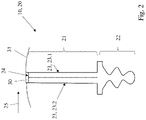
- FIG. 2 shows a component 10, namely a rotor blade 21 of a rotor blade 20, which additionally has a blade root 22, in a schematic axial view.
- the moving blade 20 is mounted in a disk, not shown here, with the blade root 22, during operation it rotates in a direction of rotation 25.
- the blade has two side surfaces 23, namely a suction side surface 23.1 and a pressure side surface 23.2.
- a coating 30 is applied to a blade tip surface 24, which serves to run in a run-in coating 31, which is only indicated schematically here.
- the blade tip surface 24 with the coating 30 in a detailed view.
- the coating 30 is applied by electrochemical deposition of a metal matrix, preferably nickel, with incorporation of hard material particles, preferably boron nitride.
- the blade tip surface 24 presents a first surface 41 that is coated, while the side surfaces 23 are second surfaces 42 and remain uncoated. Before the coating is applied, the blade tip surface 24 is ground, resulting in a sharp edge 35 toward the second surfaces 42, respectively. This is rounded before the application of the coating 30, which is done here by a combination of brushing and subsequent grinding. A concentration of the electrical field lines can thus be prevented during the subsequent galvanic deposition, so that there is no excessive application of material and the coating 30 is not applied laterally either survives.
- the respective rounding 36 is set in such a way that the respective radius of curvature R corresponds approximately to the thickness d of the coating 30 .
- FIG. 4 shows for comparison a blade tip surface 24 that is not coated according to the invention.
- the coating 30 protrudes laterally in relation to the side surfaces 23, which can be disadvantageous in terms of structural mechanics.
- This crack initiation can be favored by crystalline boron nitride, indicated here schematically.
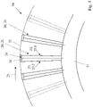
- figure 5 shows one to figure 2 alternative configuration of the moving blade 20, namely as part of a so-called blisk 50 ( blade-integrated disk, blisk).
- the blades 21 of the moving blades 20 are provided integrally on the disk 51, i.e. it is an integral part (of which in figure 5 only an excerpt is shown).
- the blade tip surfaces 24 of the blade leaves 21 are each provided with a coating 30, compare the above description in detail.
Landscapes
- Chemical & Material Sciences (AREA)
- Engineering & Computer Science (AREA)
- Materials Engineering (AREA)
- Chemical Kinetics & Catalysis (AREA)
- Electrochemistry (AREA)
- Metallurgy (AREA)
- Organic Chemistry (AREA)
- Mechanical Engineering (AREA)
- General Engineering & Computer Science (AREA)
- Inorganic Chemistry (AREA)
- Turbine Rotor Nozzle Sealing (AREA)
- Structures Of Non-Positive Displacement Pumps (AREA)
Abstract
Description
- Die vorliegende Erfindung betrifft ein Verfahren zum Beschichten eines Bauteils.
- Das zu beschichtende Bauteil kann insbesondere für eine Strömungsmaschine vorgesehen sein, etwa für ein Strahl- bzw. Mantelstromtriebwerk. Funktional gliedert sich eine solche Strömungsmaschine in Verdichter, Brennkammer und Turbine. Im Falle des Triebwerks wird bspw. angesaugte Luft vom Verdichter komprimiert und in der nachgelagerten Brennkammer mit hinzugemischtem Kerosin verbrannt. Das entstehende Heißgas, eine Mischung aus Verbrennungsgas und Luft, durchströmt die nachgelagerte Turbine und wird dabei expandiert.
- Bei der vorliegend in Rede stehenden Beschichtung kann es sich im Allgemeinen bspw. um eine Schutzbeschichtung handeln, etwa zum thermischen und/oder mechanischen Schutz einer im Verdichter- oder Heißgaskanal angeordneten Oberfläche. Die Beschichtung kann aber insbesondere auch an einer Schaufelspitze aufgebracht werden und als besonders harte Schicht dem Einlaufen in einen Einlaufbelag dienen. Dies soll ein bevorzugtes Anwendungsumfeld illustrieren, den Gegenstand aber zunächst nicht in seiner Allgemeinheit beschränken.
- Der vorliegenden Erfindung liegt das technische Problem zugrunde, ein vorteilhaftes Verfahren zum Beschichten einer Oberfläche eines Bauteils anzugeben.
- Dies wird erfindungsgemäß mit dem Verfahren nach Anspruch 1 gelöst. Dabei wird die Beschichtung auf eine erste Oberfläche des Bauteils aufgebracht, wobei zuvor eine Kante, mit der die erste an eine zweite Oberfläche grenzt, verrundet wird. Das vorherige Verrunden kann beim Beschichten eine übermäßigen Materialanlagerung an der Kante vorbeugen, die sich bspw. bei einem galvanischen Abscheideprozess aus einer Konzentration der Feldlinien an der unverrundeten, scharfen Kante ergeben könnte. Die Erfinder haben beobachtet, dass ein seitlicher Überstand der Beschichtung, der aus einem solchen übermäßigen Materialauftrag resultieren würde, später hinsichtlich der Festigkeit des Bauteils nachteilig sein kann, insbesondere unter dynamischer Belastung (z. B. Schwingfestigkeit). In dem Überstand kann bspw. unter einer Schwingungsanregung geometriebedingt die mechanische Spannung im Vergleich höher sein, insbesondere das Verhältnis Spannung/Amplitude groß werden. Dort kann dann bspw. eine Initialstelle für eine Entstehung eines Risses liegen, der sich schließlich in das Bauteil hinein ausbreiten und zu dessen Versagen führen kann.
- Bezogen auf das Beispiel eingangs kann die erste Oberfläche die Schaufelspitzenfläche und kann die zweite Oberfläche eine Seitenfläche des Schaufelblatts sein, also die Saug- und/oder Druckseitenfläche. Die Schwingungsanregung kann dann insbesondere durch benachbarte Schaufelgitter erfolgen, wodurch das Schaufelblatt in Schwingung versetzt wird, wobei die Schwingungsform Komponenten in allen Raumrichtungen enthalten kann. Das verfahrensgemäß hergestellte Bauteil kann insbesondere dann vorteilhaft Anwendung finden, wenn Moden mit hohen Schwingspannungen im Bereich der Beschichtung auftreten. Nachgewiesen werden kann die Schwingfestigkeit bspw. mittels High Cycle Fatigue Test, bei dem die Schaufel durch Fußpunktanregung im Resonanzfrequenzbereich in Schwingung versetzt und dabei ermüdet wird. Unabhängig von den Untersuchungsdetails lässt sich mit dem Verrunden der Überstand zumindest reduzieren, was strukturmechanisch von Vorteil sein kann, insbesondere im Falle einer vergleichsweise harten Beschichtung. Eine solche kann nämlich aufgrund der höheren Steifigkeit besonders rissträchtig sein.
- Bevorzugte Ausgestaltungen finden sich in den abhängigen Ansprüchen und der gesamten Offenbarung, wobei bei der Darstellung der Merkmale nicht immer in Einzelnen zwischen Verfahrens- und Vorrichtungsaspekten unterschieden wird; jedenfalls implizit ist die Offenbarung hinsichtlich sämtlicher Anspruchskategorien zu lesen. Wird bspw. ein in bestimmter Weise bearbeitetes/beschichtetes Bauteil beschrieben, ist dies zugleich Offenbarung eines entsprechenden Verfahrens, und umgekehrt. Generell sind "ein" und "eine" im Rahmen der vorliegenden Offenbarung ohne ausdrücklich gegenteilige Angabe als unbestimmte Artikel und damit stets implizit auch als "mindestens ein" bzw. "mindestens eine" zu lesen. Die erste Oberfläche kann bspw. in einer weiteren Kante an eine weitere Oberfläche des Bauteils grenzen, im Falle des Schaufelblatts kann z. B. die Schaufelspitzenfläche in jeweils einer Kante an die Saug- und auch die Druckseitenfläche. Bevorzugt werden sämtliche Kanten, in denen die erste Oberfläche an eine jeweilige andere Oberfläche grenzt, vor dem Beschichten verrundet. Die zweite Oberfläche bzw. -flächen bleibt/bleiben bevorzugt unbeschichtet, die Beschichtung wird also nur auf die erste Oberfläche aufgebracht.
- Gemäß einer bevorzugten Ausführungsform hat eine in Schritt i) eingebrachte Verrundung im Schnitt betrachtet einen Krümmungsradius R, der mindestens dem 0,5-fachen einer Dicke d der Beschichtung entspricht. Weiter und besonders bevorzugt kann der Krümmungsradius mindestens dem 0,7- bzw. 0,8-fachen der Schichtdicke entsprechen. Vorteilhafte Obergrenzen, die im Allgemeinen auch von den Untergrenzen unabhängig von Interesse sein können und offenbart sein sollen, liegen bei in der Reihenfolge der Nennung zunehmend bevorzugt dem 5-, 4-, 3- bzw. 2,5-fachen der Dicke d. Mit einem entsprechenden Radius R kann bspw. einem seitlichen Überstand der Beschichtung gegenüber der zweiten Oberfläche vorgebeugt bzw. ein solcher vollständig verhindert werden.
- Der Schnitt bzw. die Schnittebene liegt hierbei senkrecht zur Kante bzw. Kantenlinie, die sich nach der vor Schritt i) vorhandenen und mit dem Verrunden abgetragenen Kante bestimmt. Die Verrundung muss hierbei nicht zwingend einen einzigen Radius haben, sondern kann sich aus mehreren Segmenten zusammensetzen. Bevorzugt hat dann jedenfalls eines der Segmente einen entsprechenden Radius, besonders bevorzugt liegt er für sämtliche Segmente in einem entsprechenden Bereich.
- In bevorzugter Ausgestaltung wird die erste Oberfläche vor dem Verrunden materialabtragend bearbeitet, vorzugsweise durch Schleifen. Die materialabtragende Bearbeitung, mit der die erste Oberfläche bspw. für das Beschichten an sich vorbereitet werden kann, erzeugt dabei die (scharfe) Kante, die dann in Schritt i) wieder gezielt entfernt wird.
- Gemäß einer bevorzugten Ausführungsform umfasst das Verrunden der Kante eine Bearbeitung mit einer Bürste, insbesondere mit einer Industriebürste. Bevorzugt ist ein kombinierter Prozess, wird die mit der Bürste eingebrachte Verrundung nämlich anschließend noch schleifend bearbeitet. Die Verrundung kann damit geglättet werden, bspw. in einem Gleitschleifprozess. Mit den kombinierten Schritten lässt sich eine sehr weiche, also glatt verlaufende Kontur erzeugen. Im Schnitt betrachtet kann die Verrundung jeweils tangential in die jeweilige Oberfläche laufen, was generell bevorzugt ist (auch unabhängig von der Kombination bürsten/schleifen).
- Das Aufbringen der Beschichtung in Schritt i) erfolgt in bevorzugter Ausgestaltung galvanisch, also als elektrochemische Abscheidung. Das Bauteil bzw. die zu beschichtende Oberfläche wird dabei in ein Bad eingebracht und als Elektrode beaufschlagt, bspw. als Kathode zur Anlagerung von positiven Metallionen. Mit dem Verrunden kann hierbei einer Konzentration der elektrischen Feldlinien und damit einer übermäßigen Materialablagerung vorgebeugt werden, vgl. auch die vorstehenden Anmerkungen. Die Beschichtung kann aber im Allgemeinen auch mittels außenstromloser chemischer Beschichtung erfolgen oder mittels Löten.
- In bevorzugter Ausgestaltung weist die Beschichtung eine Metallmatrix, vorzugsweise aus Nickel mit eingelagerten Bornitrid Hartstoffpartikeln auf, es kann sich insbesondere um ein sog. Ni / cBN-Coating handeln. Das Bornitrid kann einerseits aufgrund seiner hohen Festigkeit von Interesse sein, insbesondere zur Präparation der Schaufelspitze zum Einlaufen. Andererseits kann das spröde Material an sich rissträchtig sein bzw. können in der Beschichtung cBN-Kristalle vorliegen, die aufgrund ihrer kantigen Struktur Initialstellen für eine Rissausbreitung darstellen können. Indem mit dem Verrunden ein Überstand der Beschichtung verringert oder vermieden wird, lässt sich das Risiko einer Rissinitialisierung zumindest absenken. Anstelle der cBN-Hartstoffpartikel können auch ähnlich harte Partikel wie z. B. Diamantpartikel oder Karbide verwendet werden.
- Wie bereits erwähnt, handelt es sich bei dem Bauteil bevorzugt um ein Schaufelblatt für eine Strömungsmaschine, das also in deren Gaskanal angeordnet wird. Bevorzugt ist das Schaufelblatt Teil einer Laufschaufel, und ist deren radial außenliegende Schaufelspitzenfläche die "erste" Oberfläche. Die dann verrundete Kante liegt also zwischen Schaufelspitzenfläche und Saug- oder Druckseitenfläche, bevorzugt werden beide Kanten verrundet. Im Allgemeinen ist auch eine Anwendung bei Verdichterleitschaufeln sowie im Turbinenbereich denkbar, bevorzugt handelt es sich um eine Verdichterschaufel.
- Die Erfindung betrifft auch ein Verfahren zum Herstellen eines solchen Bauteils, insbesondere eines Schaufelblatts, vorzugsweise einer Laufschaufel/Verdichterschaufel, und zwar durch Beschichten gemäß der vorliegenden Offenbarung.
- Ferner betrifft die Erfindung ein Bauteil für eine Strömungsmaschine, das in einem entsprechenden Verfahren hergestellt wurde, insbesondere ein Schaufelblatt einer Laufschaufel/Verdichterschaufel. Dabei ist die auf die erste Oberfläche aufgebrachte Beschichtung in einem Schnitt betrachtet allenfalls bündig mit der zweiten Oberfläche, steht sie also nicht nach außen über (sie kann leicht nach innen versetzt sein).
- Im Folgenden wird die Erfindung anhand von Ausführungsbeispielen näher erläutert, wobei die einzelnen Merkmale im Rahmen der nebengeordneten Ansprüche auch in anderer Kombination erfindungswesentlich sein können und auch weiterhin nicht im Einzelnen zwischen den unterschiedlichen Anspruchskategorien unterschieden wird.
- Im Einzelnen zeigt
- Figur 1
- eine Strömungsmaschine, nämlich ein Mantelstromtriebwerk in einem schematischen Längsschnitt;
- Figur 2
- eine Laufschaufel in einer schematischen Übersichtsdarstellung;
- Figur 3
- eine Detailansicht zur Illustration einer auf die Schaufelspitze der Laufschaufel gemäß
Figur 2 aufgebrachten Beschichtung; - Figur 4
- eine nicht erfindungsgemäße Vergleichsdarstellung einer Beschichtung;
- Figur 5
- eine Laufschaufel als Teil einer Blisk.
-
Fig. 1 zeigt eine Strömungsmaschine 1, konkret ein Mantelstromtriebwerk, in einem Axialschnitt. Die Strömungsmaschine 1 gliedert sich funktional in Verdichter 1a, Brennkammer 1b und Turbine 1c. Sowohl der Verdichter 1a als auch die Turbine 1c sind jeweils aus mehreren Stufen aufgebaut, jede der Stufen setzt sich aus einem Leit- und einem darauf folgenden Laufschaufelkranz zusammen. Im Verdichter 1a wird die angesaugte Luft komprimiert, sie wird dann in der nachgelagerten Brennkammer 1b mit hinzugemischtem Kerosin verbrannt. Der vorliegende Gegenstand richtet sich insbesondere auf eine Laufschaufel, die im Allgemeinen auch in der Turbine 1c, insbesondere jedoch im Verdichter 1a Anwendung finden kann. -
Fig. 2 zeigt ein Bauteil 10, nämlich ein Laufschaufelblatt 21 einer Laufschaufel 20, die zusätzlich einen Schaufelfuß 22 aufweist, in einer schematischen Axialansicht. Mit dem Schaufelfuß 22 wird die Laufschaufel 20 in einer hier nicht dargestellten Scheibe montiert, im Betrieb rotiert sie in einer Umlaufrichtung 25. Das Schaufelblatt weist zwei Seitenflächen 23 auf, nämlich eine Saugseitenfläche 23.1 und eine Druckseitenfläche 23.2. Auf eine Schaufelspitzenfläche 24 ist eine Beschichtung 30 aufgebracht, die dem Einlaufen in einen hier nur schematisch angedeuteten Einlaufbelag 31 dient. -
Fig. 3 zeigt die Schaufelspitzenfläche 24 mit der Beschichtung 30 in einer Detailansicht. Die Beschichtung 30 wird durch elektrochemisches Abscheiden einer Metallmatrix, vorzugsweise Nickel mit Einlagerung von Hartstoffpartikeln, vorzugsweise Bornitrid aufgebracht. Die Schaufelspitzenfläche 24 stellt eine erste Oberfläche 41 dar, die beschichtet wird, die Seitenflächen 23 sind hingegen zweite Oberflächen 42 und bleiben unbeschichtet. Vor dem Aufbringen der Beschichtung wird die Schaufelspitzenfläche 24 geschliffen, wodurch zu den zweiten Oberflächen 42 hin jeweils eine scharfe Kante 35 entsteht. Diese wird vor dem Aufbringen der Beschichtung 30 verrundet, was vorliegend durch eine Kombination aus Bürsten und anschließendem Schleifen erfolgt ist. Damit kann bei der darauffolgenden galvanischen Abscheidung einer Konzentration der elektrischen Feldlinien vorgebeugt werden, sodass dort kein übermäßiger Materialauftrag erfolgt und die Beschichtung 30 auch nicht seitlich übersteht. Die jeweilige Verrundung 36 ist so eingestellt, dass der jeweilige Krümmungsradius R in etwa der Dicke d der Beschichtung 30 entspricht. -
Fig. 4 zeigt zum Vergleich eine nicht erfindungsgemäß beschichtete Schaufelspitzenfläche 24. Die Beschichtung 30 steht seitlich gegenüber den Seitenflächen 23 über, was strukturmechanisch nachteilig sein kann. So können bspw. unter Hochfrequenzwechselbelastung, insbesondere einer Schwingungsbelastung im Schaufelspitzenbereich 24, Risse in der Beschichtung 30 entstehen und sich von dort in das Schaufelblatt 21 ausbreiten. Diese Rissinitialisierung kann durch kristallines Bornitrid, hier schematisch angedeutet, begünstigt sein. -
Fig. 5 zeigt eine zuFigur 2 alternative Ausgestaltung der Laufschaufel 20, nämlich als Teil einer sogenannten Blisk 50 (blade-integrated disk, Blisk). Dabei sind die Schaufelblätter 21 der Laufschaufeln 20 integral an der Scheibe 51 vorgesehen, handelt es sich dabei also um ein integrales Teil (von dem inFigur 5 nur ein Ausschnitt gezeigt ist). Die Schaufelspitzenflächen 24 der Schaufelblätter 21 sind dabei jeweils mit einer Beschichtung 30 versehen, vergleiche die vorstehende Beschreibung im Detail. -
Strömungsmaschine 1 Verdichter 1a Brennkammer 1b Turbine 1c Bauteil 10 Laufschaufel 20 Laufschaufelblatt 21 Schaufelfuß 22 Zwei Seitenflächen 23 Saugseitenfläche 23.1 Druckseitenfläche 23.2 Schaufelspitzenfläche 24 Umlaufrichtung 25 Beschichtung 30 Einlaufbelag 31 Kante 35 Verrundung 36 Erste Oberfläche 41 Zweite Oberfläche 42 Blisk 50 Scheibe 51
Claims (12)
- Verfahren zum Beschichten eines Bauteils (10),wobei das Bauteil (10) eine erste und eine zweite Oberfläche (41, 42) aufweist, und wobei die erste und die zweite Oberfläche (41, 42) in einer Kante (35) aneinandergrenzen,bei welchem Verfahreni) zunächst die Kante (35) zwischen der ersten und zweiten Oberfläche (41, 42) verrundet wird, undii) anschließend eine Beschichtung (30) auf die erste Oberfläche (41) aufgebracht wird.
- Verfahren nach Anspruch 1, bei welchem eine in Schritt i) zwischen der ersten und zweiten Oberfläche (41, 42) eingebrachte Verrundung (35) in einem Schnitt betrachtet einen Krümmungsradius R hat, der mindestens einem 0,5-fachen einer Dicke d der Beschichtung (30) entspricht, R ≥ 0,5·d.
- Verfahren nach Anspruch 1 oder 2, bei welchem eine in Schritt i) zwischen der ersten und zweiten Oberfläche (41, 42) eingebrachte Verrundung in einem Schnitt betrachtet einen Krümmungsradius R hat, der höchstens einem 5-fachen einer Dicke d der Beschichtung entspricht, R ≤ 5·d.
- Verfahren nach einem der vorstehenden Ansprüche, bei welchem die erste Oberfläche (41) vor Schritt i) materialabtragend bearbeitet und dabei die Kante (35) erzeugt wird.
- Verfahren nach einem der vorstehenden Ansprüche, bei welchem das Verrunden der Kante (35) in Schritt i) eine Bearbeitung mit einer Bürste umfasst.
- Verfahren nach Anspruch 5, bei welchem in Schritt i) nach der Bearbeitung mit der Bürste eine schleifende Bearbeitung erfolgt.
- Verfahren nach einem der vorstehenden Ansprüche, bei welchem die Beschichtung (30) in Schritt ii) galvanisch aufgebracht wird.
- Verfahren nach einem der vorstehenden Ansprüche, bei welchem die Beschichtung (30) Bornitrid aufweist.
- Verfahren nach einem der vorstehenden Ansprüche, bei welchem das Bauteil (10) ein Schaufelblatt (21) für eine Strömungsmaschine ist.
- Verfahren nach Anspruch 9, bei welchem die erste Oberfläche (41) eine Schaufelspitzenfläche (24) und die zweite Oberfläche (42) eine Seitenfläche (23) des Schaufelblatts (21) ist.
- Verfahren zum Herstellen eines Bauteils (10) für eine Strömungsmaschine (1), wobei das Bauteil (10) in einem Verfahren nach einem der vorstehenden Ansprüche beschichtet wird.
- Bauteil (10) für eine Strömungsmaschine, hergestellt in einem Verfahren nach Anspruch 11, bei welchem die auf die erste Oberfläche (41) aufgebrachte Beschichtung (30) in einem Schnitt betrachtet allenfalls bündig mit der zweiten Oberfläche (42) liegt, also nicht seitlich übersteht.
Applications Claiming Priority (2)
| Application Number | Priority Date | Filing Date | Title |
|---|---|---|---|
| DE102021113698 | 2021-05-27 | ||
| DE102021132256.1A DE102021132256A1 (de) | 2021-05-27 | 2021-12-08 | Verfahren zum beschichten eines bauteils |
Publications (1)
| Publication Number | Publication Date |
|---|---|
| EP4095288A1 true EP4095288A1 (de) | 2022-11-30 |
Family
ID=81748619
Family Applications (1)
| Application Number | Title | Priority Date | Filing Date |
|---|---|---|---|
| EP22173657.2A Pending EP4095288A1 (de) | 2021-05-27 | 2022-05-17 | Verfahren zum beschichten eines bauteils |
Country Status (2)
| Country | Link |
|---|---|
| US (1) | US11873571B2 (de) |
| EP (1) | EP4095288A1 (de) |
Citations (6)
| Publication number | Priority date | Publication date | Assignee | Title |
|---|---|---|---|---|
| GB2310897A (en) * | 1993-10-15 | 1997-09-10 | United Technologies Corp | Reducing stress on the tips of turbine or compressor blades |
| US20130149163A1 (en) * | 2011-12-13 | 2013-06-13 | United Technologies Corporation | Method for Reducing Stress on Blade Tips |
| US20180087387A1 (en) * | 2016-09-28 | 2018-03-29 | General Electric Company | Compositions and methods for coating metal turbine blade tips |
| EP3336221A1 (de) * | 2016-12-19 | 2018-06-20 | Franz GmbH | Verfahren zum herstellen eines gitters für ein elektrogerät |
| DE102017204243A1 (de) * | 2017-03-14 | 2018-09-20 | MTU Aero Engines AG | Dichtfin mit zumindest einer gewölbten Seitenflanke |
| DE102014218167B4 (de) * | 2014-09-11 | 2018-09-27 | MTU Aero Engines AG | Verfahren zur Schaufelspitzenpanzerung |
Family Cites Families (10)
| Publication number | Priority date | Publication date | Assignee | Title |
|---|---|---|---|---|
| US5476363A (en) * | 1993-10-15 | 1995-12-19 | Charles E. Sohl | Method and apparatus for reducing stress on the tips of turbine or compressor blades |
| US5993976A (en) * | 1997-11-18 | 1999-11-30 | Sermatech International Inc. | Strain tolerant ceramic coating |
| US20080026160A1 (en) * | 2006-05-26 | 2008-01-31 | Thomas Alan Taylor | Blade tip coating processes |
| US10113435B2 (en) * | 2011-07-15 | 2018-10-30 | United Technologies Corporation | Coated gas turbine components |
| US20150031272A1 (en) | 2013-07-23 | 2015-01-29 | General Electric Company | Machining tool and method for abradable coating pattern |
| US9932839B2 (en) | 2014-06-04 | 2018-04-03 | United Technologies Corporation | Cutting blade tips |
| DE102015208781A1 (de) | 2015-05-12 | 2016-11-17 | MTU Aero Engines AG | Kombination von Schaufelspitzenpanzerung und Erosionsschutzschicht sowie Verfahren zur Herstellung derselben |
| US10400786B2 (en) * | 2016-11-07 | 2019-09-03 | United Technologies Corporation | Coated turbomachinery component |
| US11034842B2 (en) * | 2018-12-14 | 2021-06-15 | General Electric Company | Coating for improved surface finish |
| US11492974B2 (en) * | 2020-05-08 | 2022-11-08 | Raytheon Technologies Corporation | Thermal barrier coating with reduced edge crack initiation stress and high insulating factor |
-
2022
- 2022-05-17 EP EP22173657.2A patent/EP4095288A1/de active Pending
- 2022-05-25 US US17/824,088 patent/US11873571B2/en active Active
Patent Citations (6)
| Publication number | Priority date | Publication date | Assignee | Title |
|---|---|---|---|---|
| GB2310897A (en) * | 1993-10-15 | 1997-09-10 | United Technologies Corp | Reducing stress on the tips of turbine or compressor blades |
| US20130149163A1 (en) * | 2011-12-13 | 2013-06-13 | United Technologies Corporation | Method for Reducing Stress on Blade Tips |
| DE102014218167B4 (de) * | 2014-09-11 | 2018-09-27 | MTU Aero Engines AG | Verfahren zur Schaufelspitzenpanzerung |
| US20180087387A1 (en) * | 2016-09-28 | 2018-03-29 | General Electric Company | Compositions and methods for coating metal turbine blade tips |
| EP3336221A1 (de) * | 2016-12-19 | 2018-06-20 | Franz GmbH | Verfahren zum herstellen eines gitters für ein elektrogerät |
| DE102017204243A1 (de) * | 2017-03-14 | 2018-09-20 | MTU Aero Engines AG | Dichtfin mit zumindest einer gewölbten Seitenflanke |
Also Published As
| Publication number | Publication date |
|---|---|
| US20220380926A1 (en) | 2022-12-01 |
| US11873571B2 (en) | 2024-01-16 |
Similar Documents
| Publication | Publication Date | Title |
|---|---|---|
| EP2106876B1 (de) | Verfahren zur aerodynamischen Ausformung der Vorderkante von Bliskschaufeln | |
| WO2010012255A2 (de) | Verfahren zum erzeugen einer fügeverbindung mit einkristallinem oder gerichtet erstarrtem werkstoff | |
| DE102009004791A1 (de) | Verfahren zur Herstellung der Schaufelspitzen von in BLISK-Bauweise gefertigten Laufrädern | |
| EP1430983A2 (de) | Verfahren und Vorrichtung zur Formgebung durch elektrochemisches Abtragen | |
| DE102008002944A1 (de) | Laufschaufel | |
| DE112020000789B4 (de) | Hochtemperaturbauteil und verfahren zur herstellung des hochtemperaturbauteils | |
| DE102010032326A1 (de) | Elektrode und Verfahren zum elektrochemischen Bearbeiten eines Bauteils | |
| DE102021132256A1 (de) | Verfahren zum beschichten eines bauteils | |
| EP1617972B1 (de) | Verfahren zum verrunden von kanten an bauteilen | |
| EP2125292B1 (de) | Verfahren und vorrichtung zum oberflächenstrahlen eines teilelements eines bauteils einer gasturbine | |
| DE102015209745B4 (de) | Verfahren zur Herstellung einer Tl-Blisk | |
| DE102013214781B3 (de) | Verfahren zur Reparatur eines Aufnahmehakens für Leitschaufeln | |
| EP3093371A2 (de) | Kombination von schaufelspitzenpanzerung und erosionsschutzschicht sowie verfahren zur herstellung derselben | |
| WO2019192635A1 (de) | Verfahren zum herstellen einer schaufel für eine strömungsmaschine | |
| DE102019118072A1 (de) | Rotor und Verfahren zum Herstellen eines Rotors | |
| DE102007062559A1 (de) | Verfahren zur Herstellung und Reparatur eines Bauteils und Bauteil einer Gasturbine | |
| EP4134523A2 (de) | Schaufelfussaufnahme zum aufnehmen einer laufschaufel | |
| EP4169646A1 (de) | Verfahren und vorrichtung zum einbringen einer ausnehmung in ein werkstück | |
| DE102016114452A1 (de) | Geschmiedetes Material für einen Rotor und Verfahren zur Herstellung eines Rotors unter Anwendung von geschmiedetem Material für einen Rotor | |
| US11873571B2 (en) | Method for coating a component | |
| WO2006069822A1 (de) | Verfahren zur herstellung eines lochs | |
| WO2007056978A1 (de) | Verfahren zum herstellen von metallischen bauteilen, insbesondere für turbomaschinen, mit kleinen kantenradien, sowie damit hergestelltes bauteil | |
| DE102018100535A1 (de) | Verfahren zur Einstellung der Oberflächenrauheit eines metallischen Bauteils | |
| DE102010050712A1 (de) | Bauelement einer Strömungsmaschine und Verfahren zum generativen Herstellen eines derartigen Bauelementes | |
| DE102018206705A1 (de) | Verfahren zur Herstellung einer Scheibe einer Strömungsmaschine |
Legal Events
| Date | Code | Title | Description |
|---|---|---|---|
| PUAI | Public reference made under article 153(3) epc to a published international application that has entered the european phase |
Free format text: ORIGINAL CODE: 0009012 |
|
| STAA | Information on the status of an ep patent application or granted ep patent |
Free format text: STATUS: THE APPLICATION HAS BEEN PUBLISHED |
|
| AK | Designated contracting states |
Kind code of ref document: A1 Designated state(s): AL AT BE BG CH CY CZ DE DK EE ES FI FR GB GR HR HU IE IS IT LI LT LU LV MC MK MT NL NO PL PT RO RS SE SI SK SM TR |
|
| STAA | Information on the status of an ep patent application or granted ep patent |
Free format text: STATUS: REQUEST FOR EXAMINATION WAS MADE |
|
| 17P | Request for examination filed |
Effective date: 20230530 |
|
| RBV | Designated contracting states (corrected) |
Designated state(s): AL AT BE BG CH CY CZ DE DK EE ES FI FR GB GR HR HU IE IS IT LI LT LU LV MC MK MT NL NO PL PT RO RS SE SI SK SM TR |