EP4094995A1 - Procédé de conception de porte-fusible étanche avec micro-relais iso - Google Patents
Procédé de conception de porte-fusible étanche avec micro-relais iso Download PDFInfo
- Publication number
- EP4094995A1 EP4094995A1 EP22174774.4A EP22174774A EP4094995A1 EP 4094995 A1 EP4094995 A1 EP 4094995A1 EP 22174774 A EP22174774 A EP 22174774A EP 4094995 A1 EP4094995 A1 EP 4094995A1
- Authority
- EP
- European Patent Office
- Prior art keywords
- blade
- terminal
- socket
- electrical box
- relay
- Prior art date
- Legal status (The legal status is an assumption and is not a legal conclusion. Google has not performed a legal analysis and makes no representation as to the accuracy of the status listed.)
- Pending
Links
Images


Classifications
-
- B—PERFORMING OPERATIONS; TRANSPORTING
- B60—VEHICLES IN GENERAL
- B60R—VEHICLES, VEHICLE FITTINGS, OR VEHICLE PARTS, NOT OTHERWISE PROVIDED FOR
- B60R16/00—Electric or fluid circuits specially adapted for vehicles and not otherwise provided for; Arrangement of elements of electric or fluid circuits specially adapted for vehicles and not otherwise provided for
- B60R16/02—Electric or fluid circuits specially adapted for vehicles and not otherwise provided for; Arrangement of elements of electric or fluid circuits specially adapted for vehicles and not otherwise provided for electric constitutive elements
- B60R16/023—Electric or fluid circuits specially adapted for vehicles and not otherwise provided for; Arrangement of elements of electric or fluid circuits specially adapted for vehicles and not otherwise provided for electric constitutive elements for transmission of signals between vehicle parts or subsystems
- B60R16/0238—Electrical distribution centers
-
- H—ELECTRICITY
- H01—ELECTRIC ELEMENTS
- H01R—ELECTRICALLY-CONDUCTIVE CONNECTIONS; STRUCTURAL ASSOCIATIONS OF A PLURALITY OF MUTUALLY-INSULATED ELECTRICAL CONNECTING ELEMENTS; COUPLING DEVICES; CURRENT COLLECTORS
- H01R33/00—Coupling devices specially adapted for supporting apparatus and having one part acting as a holder providing support and electrical connection via a counterpart which is structurally associated with the apparatus, e.g. lamp holders; Separate parts thereof
- H01R33/74—Devices having four or more poles, e.g. holders for compact fluorescent lamps
- H01R33/76—Holders with sockets, clips, or analogous contacts adapted for axially-sliding engagement with parallely-arranged pins, blades, or analogous contacts on counterpart, e.g. electronic tube socket
- H01R33/765—Holders with sockets, clips, or analogous contacts adapted for axially-sliding engagement with parallely-arranged pins, blades, or analogous contacts on counterpart, e.g. electronic tube socket the terminal pins having a non-circular disposition
-
- H—ELECTRICITY
- H01—ELECTRIC ELEMENTS
- H01H—ELECTRIC SWITCHES; RELAYS; SELECTORS; EMERGENCY PROTECTIVE DEVICES
- H01H50/00—Details of electromagnetic relays
- H01H50/02—Bases; Casings; Covers
- H01H50/023—Details concerning sealing, e.g. sealing casing with resin
-
- H—ELECTRICITY
- H01—ELECTRIC ELEMENTS
- H01H—ELECTRIC SWITCHES; RELAYS; SELECTORS; EMERGENCY PROTECTIVE DEVICES
- H01H50/00—Details of electromagnetic relays
- H01H50/02—Bases; Casings; Covers
- H01H50/04—Mounting complete relay or separate parts of relay on a base or inside a case
-
- H—ELECTRICITY
- H01—ELECTRIC ELEMENTS
- H01H—ELECTRIC SWITCHES; RELAYS; SELECTORS; EMERGENCY PROTECTIVE DEVICES
- H01H50/00—Details of electromagnetic relays
- H01H50/02—Bases; Casings; Covers
- H01H50/04—Mounting complete relay or separate parts of relay on a base or inside a case
- H01H50/047—Details concerning mounting a relays
- H01H50/048—Plug-in mounting or sockets
-
- H—ELECTRICITY
- H01—ELECTRIC ELEMENTS
- H01H—ELECTRIC SWITCHES; RELAYS; SELECTORS; EMERGENCY PROTECTIVE DEVICES
- H01H9/00—Details of switching devices, not covered by groups H01H1/00 - H01H7/00
- H01H9/02—Bases, casings, or covers
- H01H9/04—Dustproof, splashproof, drip-proof, waterproof, or flameproof casings
-
- H—ELECTRICITY
- H01—ELECTRIC ELEMENTS
- H01R—ELECTRICALLY-CONDUCTIVE CONNECTIONS; STRUCTURAL ASSOCIATIONS OF A PLURALITY OF MUTUALLY-INSULATED ELECTRICAL CONNECTING ELEMENTS; COUPLING DEVICES; CURRENT COLLECTORS
- H01R13/00—Details of coupling devices of the kinds covered by groups H01R12/70 or H01R24/00 - H01R33/00
- H01R13/02—Contact members
- H01R13/10—Sockets for co-operation with pins or blades
- H01R13/11—Resilient sockets
-
- H—ELECTRICITY
- H01—ELECTRIC ELEMENTS
- H01R—ELECTRICALLY-CONDUCTIVE CONNECTIONS; STRUCTURAL ASSOCIATIONS OF A PLURALITY OF MUTUALLY-INSULATED ELECTRICAL CONNECTING ELEMENTS; COUPLING DEVICES; CURRENT COLLECTORS
- H01R13/00—Details of coupling devices of the kinds covered by groups H01R12/70 or H01R24/00 - H01R33/00
- H01R13/40—Securing contact members in or to a base or case; Insulating of contact members
- H01R13/42—Securing in a demountable manner
-
- H—ELECTRICITY
- H01—ELECTRIC ELEMENTS
- H01R—ELECTRICALLY-CONDUCTIVE CONNECTIONS; STRUCTURAL ASSOCIATIONS OF A PLURALITY OF MUTUALLY-INSULATED ELECTRICAL CONNECTING ELEMENTS; COUPLING DEVICES; CURRENT COLLECTORS
- H01R13/00—Details of coupling devices of the kinds covered by groups H01R12/70 or H01R24/00 - H01R33/00
- H01R13/46—Bases; Cases
- H01R13/502—Bases; Cases composed of different pieces
-
- H—ELECTRICITY
- H01—ELECTRIC ELEMENTS
- H01R—ELECTRICALLY-CONDUCTIVE CONNECTIONS; STRUCTURAL ASSOCIATIONS OF A PLURALITY OF MUTUALLY-INSULATED ELECTRICAL CONNECTING ELEMENTS; COUPLING DEVICES; CURRENT COLLECTORS
- H01R13/00—Details of coupling devices of the kinds covered by groups H01R12/70 or H01R24/00 - H01R33/00
- H01R13/46—Bases; Cases
- H01R13/52—Dustproof, splashproof, drip-proof, waterproof, or flameproof cases
- H01R13/5202—Sealing means between parts of housing or between housing part and a wall, e.g. sealing rings
-
- H—ELECTRICITY
- H01—ELECTRIC ELEMENTS
- H01R—ELECTRICALLY-CONDUCTIVE CONNECTIONS; STRUCTURAL ASSOCIATIONS OF A PLURALITY OF MUTUALLY-INSULATED ELECTRICAL CONNECTING ELEMENTS; COUPLING DEVICES; CURRENT COLLECTORS
- H01R13/00—Details of coupling devices of the kinds covered by groups H01R12/70 or H01R24/00 - H01R33/00
- H01R13/46—Bases; Cases
- H01R13/52—Dustproof, splashproof, drip-proof, waterproof, or flameproof cases
- H01R13/5219—Sealing means between coupling parts, e.g. interfacial seal
-
- H—ELECTRICITY
- H02—GENERATION; CONVERSION OR DISTRIBUTION OF ELECTRIC POWER
- H02B—BOARDS, SUBSTATIONS OR SWITCHING ARRANGEMENTS FOR THE SUPPLY OR DISTRIBUTION OF ELECTRIC POWER
- H02B1/00—Frameworks, boards, panels, desks, casings; Details of substations or switching arrangements
- H02B1/26—Casings; Parts thereof or accessories therefor
- H02B1/28—Casings; Parts thereof or accessories therefor dustproof, splashproof, drip-proof, waterproof or flameproof
-
- H—ELECTRICITY
- H02—GENERATION; CONVERSION OR DISTRIBUTION OF ELECTRIC POWER
- H02B—BOARDS, SUBSTATIONS OR SWITCHING ARRANGEMENTS FOR THE SUPPLY OR DISTRIBUTION OF ELECTRIC POWER
- H02B1/00—Frameworks, boards, panels, desks, casings; Details of substations or switching arrangements
- H02B1/26—Casings; Parts thereof or accessories therefor
- H02B1/46—Boxes; Parts thereof or accessories therefor
- H02B1/48—Mounting of devices therein
-
- H—ELECTRICITY
- H02—GENERATION; CONVERSION OR DISTRIBUTION OF ELECTRIC POWER
- H02G—INSTALLATION OF ELECTRIC CABLES OR LINES, OR OF COMBINED OPTICAL AND ELECTRIC CABLES OR LINES
- H02G3/00—Installations of electric cables or lines or protective tubing therefor in or on buildings, equivalent structures or vehicles
- H02G3/02—Details
- H02G3/08—Distribution boxes; Connection or junction boxes
- H02G3/088—Dustproof, splashproof, drip-proof, waterproof, or flameproof casings or inlets
-
- H—ELECTRICITY
- H01—ELECTRIC ELEMENTS
- H01H—ELECTRIC SWITCHES; RELAYS; SELECTORS; EMERGENCY PROTECTIVE DEVICES
- H01H50/00—Details of electromagnetic relays
- H01H50/02—Bases; Casings; Covers
- H01H50/04—Mounting complete relay or separate parts of relay on a base or inside a case
- H01H2050/049—Assembling or mounting multiple relays in one common housing
-
- H—ELECTRICITY
- H01—ELECTRIC ELEMENTS
- H01H—ELECTRIC SWITCHES; RELAYS; SELECTORS; EMERGENCY PROTECTIVE DEVICES
- H01H45/00—Details of relays
- H01H45/14—Terminal arrangements
-
- H—ELECTRICITY
- H01—ELECTRIC ELEMENTS
- H01R—ELECTRICALLY-CONDUCTIVE CONNECTIONS; STRUCTURAL ASSOCIATIONS OF A PLURALITY OF MUTUALLY-INSULATED ELECTRICAL CONNECTING ELEMENTS; COUPLING DEVICES; CURRENT COLLECTORS
- H01R33/00—Coupling devices specially adapted for supporting apparatus and having one part acting as a holder providing support and electrical connection via a counterpart which is structurally associated with the apparatus, e.g. lamp holders; Separate parts thereof
- H01R33/88—Coupling devices specially adapted for supporting apparatus and having one part acting as a holder providing support and electrical connection via a counterpart which is structurally associated with the apparatus, e.g. lamp holders; Separate parts thereof adapted for simultaneous co-operation with two or more identical counterparts
Definitions
- Embodiments of the present disclosure relate to electrical boxes that house ISO micro relays and, more particularly, to electrical boxes that satisfy IP67 and IP69K Ingress Protection ratings.
- PDM power distribution module
- One of those components may be a relay, which is an electrically operated switch.
- An ISO relay is one which adheres to a standard pattern for its electrical terminals that has been spelled out by the International Standards Organization (ISO).
- ISO micro relays are used in automotive switching applications such as for lamps and motors.
- ISO-style relays also generally plug into their end application via sockets, such as a PDM. Housing an ISO micro relay in a PDM is not difficult but providing a PDM that satisfies the IP67/IP69K Ingress Protection ratings is challenging.
- An exemplary embodiment of an electrical box in accordance with the present disclosure may include a housing with a relay socket.
- the relay socket consists of a first, second, and third blade sockets, and first, second, and third terminal seats.
- the second blade socket is adjacent and parallel to the first blade socket.
- the third blade socket is orthogonal to the first blade socket and adjacent to the second blade socket.
- the relay socket is adapted to accept an ISO micro relay.
- the first terminal seat, adapted to receive a first terminal is located in a center position of the first blade socket.
- the second terminal seat, adapted to receive a second terminal is located in a center position of the second blade socket.
- the third terminal seat, adapted to receive a third terminal is located in one end of the third blade socket.
- An exemplary embodiment of a relay socket in accordance with the present disclosure may include first, second, and third blade sockets and first, second, and third terminal seats.
- the first blade socket is adapted to receive a first blade of an ISO micro relay and has a first edge and a second edge.
- the second blade socket adjacent and parallel to the first blade socket, is adapted to receive a second blade of the ISO micro relay and has a third edge and a fourth edge, the third edge being proximate the first edge and the fourth edge being proximate the second edge.
- the third blade socket adjacent and parallel to the second blade socket, is adapted to receive a third blade of the ISO micro relay and has a fifth edge and a sixth edge, the fifth edge being proximate the third edge and the sixth edge being proximate the fourth edge.
- the first terminal seat adapted to receive a first terminal, is located at the first edge of the first blade socket.
- the second terminal seat adapted to receive a second terminal, is located at the fourth edge of the second blade socket.
- the third terminal seat adapted to receive a third terminal, is located at the fifth edge of the third blade socket.
- An exemplary embodiment of a housing for use in an electrical box in accordance with the present disclosure may include a component side and a terminal side and also includes a relay socket which is adapted to receive an ISO micro relay.
- the relay socket includes first, second, and third cross-shaped openings.
- the first cross-shaped opening is adapted to receive a first blade of the ISO micro relay on the component side and a first terminal on the terminal side.
- the second cross-shaped opening is adapted to receive a second blade of the ISO micro relay on the component side and a second terminal on the terminal side.
- the third cross-shaped opening is adapted to receive a third blade of the ISO micro relay on the component side and a third terminal on the terminal side.
- the second cross-shaped opening is identical to the third cross-shaped opening.
- a novel electrical box design, suitable for ISO Micro relays, is disclosed herein.
- the electrical box is adapted to support IP67 and IP69K Ingress Protection ratings.
- the housing of the electrical box is molded with blade sockets that correspond to blade positions of the ISO micro relays.
- the housing is also molded with terminal seats and cylindrical openings which vary, depending on the blade socket, enabling terminals of different sizes, orientations, and positions relative to the respective blades, to be easily inserted into the back of the housing. The resulting position of the terminals ensures that electrical connections to the ISO micro relay are made and ingress protection of components inside the electrical box is ensured.
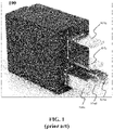
- FIG. 1 is a representative perspective illustration of a relay 100, according to the prior art.
- the relay 100 is one which adheres to a standard pattern for its electrical terminals that has been spelled out by the International Standards Organization (ISO), and thus may be thought of as an ISO relay. Further, because the relay is somewhat smaller than standard relays, this type of relay is known as an ISO micro relay.
- ISO micro relays 100 are standard off-the-shelf components with five blades 104a-e (collectively, "blades 104").
- the ISO micro relay 100 establishes a connection to a circuit by being plugged into a socket.
- the socket may be part of an electrical box, enabling a connection to be established between the ISO micro relay and a switching application.
- the blades 104 of the ISO micro relay 100 are oriented in a particular configuration. Two of the blades 104a and 104b are oriented in one way (top of the relay and horizontally disposed, in the view of FIG. 1 ) while the remaining three blades 104c, 104d, and 104e are orientated in another way (bottom of the relay and vertically disposed, in the view of FIG. 1 ), which is orthogonal to the blades 104a and 104b.
- the blades 104a and 104b are also a different size (wi) than the blades 104c, 104d, and 104e ( w 2 ), with w 1 > w 2 .
- the blades 104a and 104b are spaced a distance, d 1 , apart, while the spacing between blades 104c and 104d and blades 104d and 104e are a distance, d 2 , apart, with d 2 being smaller than d 1 .
- the blades are all approximately the same length, l .
- the ISO micro relay 100 terminates in a socket to create an electrical connection to the device or circuit being supported by the relay, where the socket further holds the relay in place.
- the pass-through socket housing the ISO micro relay would be sealed.
- the layout of the ISO micro relay 100, where the blades 104 are oriented in a close configuration, however, does not enable the sealing of the socket housing.
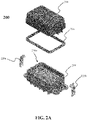
- FIGs. 2A-2C are representative illustrations of an electrical box 200, according to exemplary embodiments.
- FIG. 2A is an exploded perspective view of the electrical box;
- FIG. 2B is a perspective view of the electrical box showing the component side of the housing;
- FIG. 2C is a bottom view of the electrical box showing the terminal side of the housing.
- the novel electrical box 200 supports ISO micro relays, such as the ISO micro relay 100 of FIG. 1 and provides IP67 and IP69K protection against ingress of water or other contaminants into the electrical box, thus protecting all components within the electrical box.
- the housing 218 of the electrical box 200 has two opposing sides, a component side of housing 218a ( FIGs. 2A and 2B ) and a terminal side of housing 218b ( FIG. 2C ), both of which are shown and described in greater detail herein.
- Four ISO micro relays 100 FIG. 1
- the number of relays shown in the electrical box 200 is not meant to be limiting.
- the relays 100 and fuses 208 are seated in the component side of housing 218a and power cables 210 and terminals 202 are connected to the terminal side of housing 218b.
- a cover 214 fits over the housing 218 to protect the relays 100 and fuses 208.
- a seal 216 disposed between the cover 214 and the housing 218 provides additional protection against ingress of water/contaminants.
- Latches 220a and 220b are fastened on either side of the cover 214 and also engage with the housing 218. The latches 220 secure the cover 214 to the housing 218.
- latches 220 secure the cover 214 to the housing 218.
- the electrical box 200 is designed to provide electrical connection between the relays 100 and external components by way of the power cable 210 and terminals 202. Since the relays 100 each include five blades 104 ( FIG. 1 ), there are five dedicated terminals 202 associated with each relay, one for each blade. The relays 100 are inserted into dedicated sockets in the component side of housing 218a. The terminals 202 are connected to the terminal side of housing 218b such that they establish a connection to respective relays 100 through the housing 218. Once power is delivered to the electrical box 200 through the power cable 210, an electrical connection is established between the relays 100 and respective terminals 202.
- a relay socket for receiving an ISO micro relay is illustrated on both sides of the housing 218.
- Relay socket 206a is featured on the component side of housing 218a ( FIG. 2B ) and relay socket 206b is featured on the terminal side of housing 218b ( FIG. 2C ) (collectively, "relay socket 206").
- the relay 100 of FIG. 1 may fit in the relay socket 206, for example.
- the relay socket 206 is to be connected to five terminals 202, one for each blade of the ISO micro relay, to establish an electrical connection between the relay and circuitry connected to the electrical box 200.
- the electrical box 200 is designed with the relays 100 and terminals 202 in mind, the relays and terminals are not part of the electrical box. Instead, both the relays 100 and terminals 202 are standard, off-the-shelf parts purchased by customers who utilize the electrical box 200. To understand the challenges of designing the electrical box 200 to be IP67- and IP69K-compliant, a better understanding of the terminals 202 is warranted.
- FIGs. 3A and 3B are representative drawings of the terminal 202, according to the prior art.
- the terminal 202 is attached to one blade 104 of the ISO micro relay 100 ( FIG. 1 ).
- the terminal 202 features a device cable 308 and a rubber seal 314, along with a three-part connector consisting of a socket interface 302, a wire crimp area 310, and a seal crimp area 312.
- the socket interface 302 includes clips 306a and 306b (collectively, "clips 306"), which are the parts of the terminal 202 that will mate with the blade 104.
- the terminal 202 may be attached to components other than blades, such as busbars or other electrically conductive elements.
- the clips 306 are spring-tensioned to be initially touching one another before attachment to something. When pushed against an edge of the blade 104, the two clips 306 separate just enough that the blade fits between the two clips. The terminal 202 thus becomes fixably attached to the blade 104. This attachment allows an electrical connection to be established between the ISO micro relay 100 and the terminal 202. One clip 306a slides against one side of the blade 104 while the other clip 306b slides against the other side of the blade. The spring tension causes the clip 306 to remain connected to the blade 104 until the terminal 202 is removed from the blade.
- the clips 306 of the socket interface 302, as well as the wire crimp area 310 and seal crimp area 312 are made of an electrically conductive material.
- a current will pass through the blade 104 to the clips 306, through the socket interface 302, the wire crimp area 310, the seal crimp area 312, and through the wiring inside the device cable 308, and vice-versa.
- the terminal 202 facilitates flow of electrical current between the ISO micro relay 100 and whatever device/circuit the device cable 308 is connected to.
- the rubber seal 314 of the terminal 202 has a diameter, d3 ( FIG. 3B ), while the socket interface 302 has a width, w 3 ( FIG. 3A ).
- the diameter, d 3 , of the rubber seal 314 is larger than the width, w 3 , of the socket interface 302, the width, w 4 , of the wire crimp area 310, and the width, w 5 , of the seal crimp area.
- the diameter, d 3 , of the rubber seal 314 is the widest part of the terminal 202.
- the terminal 202 is available in different sizes.
- the electrical box 200 supports terminals 202 of two different sizes for connection to the ISO micro relay 100.
- each of the terminals 202 ends at the relay socket 206b of the electrical box 200.
- each blade 104 automatically fits into the two clips 306 of its respective terminal 202, for a total of five terminals.
- each terminal 202 includes a rubber seal 314, which is the widest part of the terminal.
- each terminal 202 will need a space greater than the diameter, d 1 , of the rubber seal 314 in the relay socket 206b.
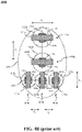
- FIGs. 4A and 4B are representative illustrations of the relay socket portion of an electrical box 400, according to the prior art.
- FIG. 4A is a top view of a relay socket 406 that is part of the prior art electrical box 400 while FIG. 4B shows relative placement of elements of the relay socket 406.
- the relay socket 406 includes five blade sockets 404a-e (collectively, "blade sockets 404"), for receiving five blades of an ISO micro relay, such as the ISO micro relay 100 ( FIG. 1 ).
- the blade sockets 404 are oriented in a particular configuration. Two of the blade sockets 404a and 404b are oriented in one way (top of the relay socket 406 and horizontally disposed, in the illustrated views). The remaining three blade sockets 404c, 404d, and 404e are orientated in another way (bottom of the relay socket 406 and vertically disposed, in the illustrated views), with the blade sockets 404c, 404d, and 404e being orthogonal to the blade sockets 404a and 404b.
- the blade sockets 404a and 404b are of a first size ( w 1 ), to correspond with the size, w 1 , of blades 104a and 104b ( FIG.
- the blade sockets 404c, 404d, and 404e are of a different size ( w 2 ), to correspond with the size, w 2 , of blades 104c, 104d, and 104e, with w 1 > w 2 .
- the blade sockets 404a and 404b are spaced a distance, d 1 , apart, corresponding to the distance, d 1 , between blades 104a and 104b; the spacing between blade sockets 404c and 404d ( d 2 ) correspond with the distance between blades 104c and 104d; and the spacing between blade sockets 404d and 404e (also d 2 ) correspond with the distances between blades 104d and 104e, with d2 ⁇ d 1 . Further, though shown in two dimensions, each blade socket 404 has a depth sufficient to receive the length, l , of respective blades. Thus, the blade sockets 404 are sized to accept respective blades 104 of the ISO micro relay 100.
- FIGs 4B feature blade location indicators (patterned with upward diagonal stripes) (collectively, "blade location indicators 414”) and clip location indicators (patterned with downward diagonal stripes) (collectively, “clip location indicators 416").
- the blade location indicators 414 and the clip location indicators 416 illustrate how blades and terminals are seated into the respective blade sockets 404.
- the blade location indicators 414 show that each blade essentially "fills” the respective blade sockets 404.
- the blades 104 of the ISO micro relay 100 plug into the front of the relay socket 406 of the prior art electrical box 400 while the clips, such as the clips 306 of the terminal 202 ( FIGs. 3A and 3B ) plug into the back of the relay socket.
- FIG. 4B thus indicates relative placement of the terminals 202 and the blades 104 once the ISO micro relay 100 is inserted into the relay socket 406 of the prior art electrical box 400.
- blade location indicator 414a and clip location indicators 416a and 416b are shown; for blade socket 404b, blade location indicator 414b and clip location indicators 416c and 416d are shown.
- a position indicator 418 (disposed vertically in FIG. 4B ) indicates that clip location indicators 416a-416d line up in the same plane with one another.
- blade location indicator 414c and clip location indicators 416e and 416f are shown; for blade socket 404d, blade location indicator 414d and clip location indicators 416g and 416h are shown; for blade socket 404e, blade location indicator 414e and clip location indicators 416i and 416j are shown.
- a position indicator 420 (disposed horizontally in FIG. 4B ) indicates that clip position indicators 414e-414j line up in the same plane with one another.
- the position indicators 418 and 420 thus show the typical "centered" location for where the clips, and thus terminals, are usually located (on the other side of the prior art electrical box 400).
- the position indicator 418 show that the clip location indicators 416a-d are in the same plane.
- Blades 104a and 104b are a first width, w 1
- blades 104c, 104d, and 104e are a second width, w 2 , with w 2 ⁇ w 1 .
- blades 104a and 104b with terminals 202 that are a first size
- blades 104c, 104d, and 104e are joined with terminals that are a second, smaller size.
- the rubber seal 314 of the terminal 202 has a diameter, d3, which is as wide or wider than any other component of the terminal.
- the rubber seal 314 governs the ability to successfully connect a terminal 202 to each blade of the ISO micro relay 100 into the relay socket 406 of the prior art electrical box 400.
- the terminal 202 is a standard, off-the-shelf part available for purchase by a customer, where that customer also purchases the prior art electrical box 400.
- the customer may populate the prior art electrical box 400 with fewer relays and fuses than the electrical box supports.
- the relays for example, the customer purchases the number of relays needed for the particular application, then purchases five terminals for each relay obtained, one terminal for each blade. Because two of the blades of each relay have larger dimensions than the remaining three blades, the customer would purchase two terminals of one size, and three terminals of a different, smaller size for each relay. Thus, the relays support terminals of two different sizes.
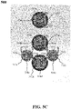
- FIG. 4B shows two different sizes of rubber seals.
- FIG. 4B illustrates how the rubber seal of the terminal 202 fits, relative to each blade socket 404.
- Blade sockets 404a and 404b including rubber seal location indicators 422a and 422b, respectively (collectively, “rubber seal location indicators 422").
- Blade sockets 404c, 404d, and 404e include rubber seal location indicators 424a, 424b, and 424c (collectively, “rubber seal location indicators 424"). Rubber seal location indicators 422 are larger than rubber seal location indicators 424.
- the blade 104 is inserted into the blade socket 404 on the component side of the prior art electrical box 400, while the clips 306 and the rubber seals 314 of the terminals 202, one for each blade 104, are "below” or “behind” the blade socket 404 on the terminal side of the prior art electrical box.
- clip location indicators 416b (for blade socket 404a) and 416c (for blade socket 404b) are spaced apart enough to fit the larger rubber seal around each terminal, as rubber seal location indicators 422a and 422b are not touching one another.
- the distance, d 1 , between blade location indicators 414a and 414b is thus large enough to support the larger rubber seal.
- blade sockets 404c-e even though they are to be fit with terminals having the smaller rubber seals.
- the position indicator 420 shows that the clip location indicators 416e-416j are in the same plane. But clip location indicator 416i (for blade socket 404e) is very close to clip location indicator 416h (for blade socket 404d) and clip location indicator 416g (for blade socket 404d) is very close to clip location indicator 416f (for blade socket 404c).
- the terminals 202 that are to be connected on the backside of the prior art electrical box 400 for three of the blade socket 404c-e will be too close together to include even the smaller rubber seal around each terminal.
- the novel electrical box 200 has a relay socket design that is different from what is shown in FIGs. 4A and . 4B , according to exemplary embodiments. Based on the layout of its relay socket, as shown and described below, the novel electrical box 200 is able to provide IP67 and IP69K protection against ingress of water into the electrical box, thus sealing and protecting the ISO micro relays within the electrical box.
- FIGs. 5A-5C are representative drawings of the component side of the electrical box 200 of FIGs. 2A and 2B , according to exemplary embodiments.
- FIGs. 5A and 5B are close-up views of the electrical box 200 of FIGs. 2A and 2B , according to exemplary embodiments, with the relay socket 206a (component side of housing 218a) being shown in more detail.
- FIG. 5C is a head-on view of a terminal arrangement 500 supported by the electrical box 200, in exemplary embodiments.
- FIG. 5A includes terminal seats while FIG. 5B shows the actual terminals.
- Five blade sockets 504a-e are shown, one for each blade of the ISO micro relay (collectively, "blade sockets 504").
- For the ISO micro relay 100 FIG.
- blade 104a fits in blade socket 504a
- blade 104b fits in blade socket 504b
- blade 104c fits in blade socket 504c
- blade 104d fits in blade socket 504d
- blade 104e fits in blade socket 504e.
- the blade sockets 504 are oriented in a particular configuration. Two of the blade sockets 504a and 504b are oriented in one way (top of the relay socket 206a and horizontally disposed, in the illustrated views). The remaining three blade sockets 504c, 504d, and 504e are orientated in another way (bottom of the relay socket 206a and vertically disposed, in the illustrated views), with the blade sockets 504c, 504d, and 504e being orthogonal to the blade sockets 504a and 504b.
- the blade sockets 504a and 504b are of a first size ( w 1 ), to correspond with the size, w 1 , of blades 104a and 104b ( FIG.
- the blade sockets 504c, 504d, and 504e are of a different size ( w 2 ), to correspond with the size, w 2 , of blades 104c, 104d, and 104e, with w 1 > w 2 .
- the blade sockets 504a and 504b are spaced a distance, d 1 , apart, corresponding to the distance, d 1 , between blades 104a and 104b; the spacing between blade sockets 504c and 504d ( d 2 ) correspond with the distance between blades 104c and 104d; and the spacing between blade sockets 504d and 504e (also d 2 ) correspond with the distances between blades 104d and 104e, with d2 ⁇ d 1 .
- each blade socket 504 has a depth sufficient to receive the length, l , of respective blades.
- the blade sockets 504 are sized to accept respective blades 104 of the ISO micro relay 100.
- the blades 104 of the ISO micro relay 100 essentially "fill" the respective blade sockets 504.
- terminal seats 506a-e illustrate the relative position of terminals "behind" respective blade sockets 504. Recall that the terminals 202 are purchased by customers separate from purchasing the electrical box 200. If an ISO micro relay 100 is to be installed into the electrical box 200, the customer will purchase five terminals 202 for each ISO micro relay being installed. The terminal seats 506 thus indicate placement of terminals, such as the terminals 202 ( FIGs. 3A and 3B ) relative to the blade sockets 504 once the ISO micro relay 100 is inserted into the relay socket 206a of the novel electrical box 200.
- terminal seat 506a is shown; for blade socket 504b, terminal seat 506b is shown.
- a position indicator 518 (disposed vertically in FIG. 5A ) indicates that the terminal seats 506a and 506b line up in the same plane with one another.
- terminal seat 506c For blade socket 504c, terminal seat 506c is shown; for blade socket 504d, terminal seat 506d is shown; for blade socket 504e, terminal seat 506e is shown.
- a position indicator 520 (disposed horizontally in FIG. 5A ) indicates that terminal seats 506c and 506e line up in the same plane with one another. However, a second position indicator 522 (disposed horizontally in FIG. 5A ) indicates that terminal seat 506d is in a different plane than terminal seats 506c and 506e.
- the relay socket 206a has an "off-centered" layout or geometry which allows standard terminals and wire seals to be used in the electrical box 200, in exemplary embodiments. Further, in exemplary embodiments, the positioning of the terminals ensures that the electrical box 200 supports the IP67 and IP69K ingress protection protocols.
- the housing of the electrical box 200 is molded to have openings for fitting the blade of the ISO micro relay (on the component side) and the terminal (on the terminal side). These openings may be characterized as being "cross-shaped", the cross consisting of two intersecting bars, the first bar being disposed in one orientation and the second bar being disposed in another, right-angle orientation, such that the two bars are perpendicular to one another.
- the component side of housing 218a is molded such that resulting "cross-shaped openings" are formed in the housing for both the blades and their respective terminals. Because of the size and orientation of both the blades and the terminals, as well as the relative position of the terminals behind respective blade sockets, the cross-shaped openings vary somewhat, in some embodiments.
- the cross-shaped openings for blade sockets 504a and 504b for example, have a horizontal portion sized to accept the larger blades (104a and 104b) and a vertical portion sized to accept larger terminals in a first orientation, each resulting in a first cross-shape.
- Blade sockets 504c and 504e have vertical portions sized to accept the smaller blades (104c and 104e) and a horizontal portions sized to accept smaller terminals in a second orientation, each resulting in a second cross-shape.
- Blade socket 504d has a vertical portion sized to accept a smaller blade (104d) and a horizontal portion sized to accept a larger terminal in the second orientation, resulting in a third cross-shape. Further, since the terminal part is oriented at one edge of the blade socket, the cross-shape of blade sockets 504c and 504e looks somewhat like a small letter "t" while the cross-shape of blade socket 504d looks like an upside down small letter "t", given that the terminal part is at the opposing edge, with the vertical part of the cross being fatter for the blade socket 504d.
- the molding of the housing 218 thus facilitates the placement of the off-the shelf ISO micro relay and terminal components into the electrical box 200.
- the novel electrical box 200 allows for standard terminal terminals and rubber seals to be installed in offset blade sockets.
- the terminals are visible through the openings of respective blade sockets 504.
- Terminal 508a is visible in blade socket 504a; terminal 508b is visible in blade socket 504b; terminal 508c is visible in blade socket 504c; terminal 508d is visible in blade socket 504d; and terminal 508e is visible in blade socket 504e (collectively, "terminals 508").
- terminals 508c and 508d are of a smaller size than terminals 508a, 508b, and 508d.
- the terminals 508a and 508b are in a first orientation while terminals 508c, 508d, and 508e are in a second orientation, the second orientation being orthogonal to the first orientation.
- Terminal 508a includes clips 510a and 510b; terminal 508b includes clips 510c and 510d; terminal 508c includes clips 510e and 510f; terminal 508d includes clips 510g and 510h; and terminal 508e includes clips 510i and 510j (collectively, "clips 510").
- the clips 510 will move slightly to receive the blades.
- FIG. 5B when blade 104a of ISO micro relay 100 ( FIG. 1 ) is inserted in blade socket 504a, the clip 510a of the terminal 508a will move upward slightly, while the clip 510b will move downward slightly.
- the five terminals 508 are shown, with respective clips 510, as before.
- the terminal arrangement 500 is from the component side of the electrical box, with the electrical box not shown.
- the terminal seats 506 ( FIG. 5A ) are arranged to accommodate the terminals 508, in exemplary embodiments, with the terminals 508a and 508b arranged in one direction (with respective clips 510 to be attached above and below respective blades) and the terminals 508c, 508d, and 508e are arranged at right angles to terminals 508a and 508b (with respective clips 510 to be attached to the left and right of respective blades).
- the terminal arrangement 500 shows that the terminals 508c and 508e are smaller than terminals 508a, 508b, and 508d.
- the terminal arrangement 500 also shows rubber seals for each terminal, with the rubber seals being "behind” the clips 510.
- Rubber seals 512a, 512b, and 512d are a first size, with rubber seals 512c and 512e being a second, smaller size (collectively, "rubber seals 512").
- the rubber seal 314 of the terminal 202 ( FIG. 3B ) has a diameter, d3, while the socket interface 302 has a width, w 3 ( FIG. 3A ), with the diameter, d 3 , being larger than the width, w 3 , and thus the widest part of the terminal 202. This is true even for terminals of different sizes.
- the rubber seals 512 are each visible, as the diameter of each rubber seal is larger than that of the other components of each terminal.
- the novel approach to terminal alignment shown in FIGs. 5A-5C allows a sealed connection to be made between each blade 104 of the ISO micro relay 100 and each terminal 202.
- the terminals 508 can be installed into and removed from the electrical box 200 with industry standard methods.
- FIGs. 6A and 6B are representative drawings of the terminal side of housing 218b of the electrical box 200, according to exemplary embodiments.
- the illustrations show how the "offset" configuration of the relay socket 206a (component side of housing 218a) of FIG. 5A and 5B allows space for each terminal to have a standard seal in the relay socket 206b (terminal side of housing 218b).
- the novel configuration thus facilitates placement of the terminals, including the rubber seals, in the relay sockets of the electrical box 200, according to exemplary embodiments, such that IP67 and IP69K ingress protection is obtained.
- the terminal side of the relay socket 206b features elements that mate with the ISO micro relay 100 once inserted into the blade sockets 504 on the component side of the relay socket 206a.
- Blade socket locations 604a-e are indicated as the backside locations of respective blade sockets 504a-e in FIGs. 5A and 5B and are the locations where terminals, such as terminals 202, are disposed. Accordingly, in blade socket location 604a, an insulated wire 606a surrounded by a rubber seal 608a, is shown. The insulated wire 606a and rubber seal 608a are both part of a terminal, such as terminal 202 ( FIGs.
- blade socket location 604b features insulated wire 606b surrounded by rubber seal 608b; blade socket location 604c features insulated wire 606c surrounded by rubber seal 608c; blade socket location 604d features insulated wire 606d surrounded by rubber seal 608d; and blade socket location 604e features insulated wire 606e surrounded by rubber seal 608e (collectively, "insulated wires 606" and "rubber seals 608").
- the blade socket locations 604a, 604b, and 604d are larger than the blade socket locations 604c and 604e. This corresponds to the terminals 508a, 508b, and 508d being larger in size than the terminals 508c and 508d ( FIGs. 5A-5C ). Although the orientation of terminals 508a and 508b are orthogonal to the orientation of terminals 508c, 508d, and 508e, this is not evident on the terminal side of the relay socket 206b.
- the blade socket locations 604e and 604d there is a space, s; similarly, between the blade socket locations 604d and 604c, there is a space, s.
- the space, s ensures that there is sufficient spacing so that respective rubber seals 608 do not overlap one another.
- the tight fitting of the rubber seals 608 of the terminals 202 provides a seal against the housing of the electrical box 200, preventing water or contaminants from entering the electrical box.
- the electrical box 200 satisfies both IP67 (total protection from dust and protected from temporary liquid immersion) and IP69K (proven to resist ingress of high temperature and pressure wash) Ingress Protection ratings with the novel arrangement of the relay socket.
- FIG. 6B is a second terminal side view of the electrical box 200, again featuring the relay socket 206b.
- blade location indicators 614a-e (collectively, “blade location indicators 614") for the ISO micro relay 100 are shown.
- Blade location indicators 614a and 614b, for the blade socket locations 604a and 604b, respectively, indicate that respective terminals are positioned in the middle of the blade socket location.
- the insulated wire 606a for example, is disposed in the center of the blade location indicator 614a, and the rubber seal 608a is also disposed such that its center is in the center of the blade location indicator and its circumferential edges are equidistant from the left and right edges of the blade location indicator.
- the insulated wire 606b and rubber seal 608b both are positioned in the middle of the blade location indicator 614b.
- the blade location indicators 614c, 614d, and 614e show that the terminals are not positioned in the middle of the blade socket locations but are each in offset positions relative to the blade sockets.
- Insulated wire 606c and rubber seal 608c are disposed at one end of the blade location indicator 614c (to the end closer to blade location indicator 614b).
- insulated wire 606e and rubber seal 608e are disposed at one end of the blade location indicator 614c (to the end closer to blade location indicator 614b).
- terminals connect at the top, not at the center, of the blades 104c and 104e.
- Insulated wire 606d and rubber seal 608d are disposed at the other end of the blade location indicator 614d (end that is farther away from blade location indicator 614b).
- a terminal connects at the bottom, not the center, of the blade 104d. In this manner, all blades 104 of the ISO micro relay 100 are connected to terminals and the rubber seals 608 are able to be positioned flush against the housing of the electrical box 200, ensuring that the electrical box satisfies IP67 and IP69K ingress protection ratings.
- FIGs. 7A and 7B are representative drawings of an ISO micro relay 700 connected to terminals, where the terminals are arranged as they would be in the electrical box 200, according to exemplary embodiments.
- FIG. 7A shows a perspective view of the ISO micro relay 700 without housing while
- FIG. 7B shows a side view of the ISO micro relay 700 within the housing 218 of the electrical box 200.
- the ISO micro relay 700 includes blades 704a-e, arranged just as with the ISO micro relay 100 ( FIG. 1 ).
- Terminal 706a connects to blade 704a; terminal 706b connects to blade 704b; terminal 706c connects to blade 704c; terminal 706d connects to blade 704d; and terminal 706e connects to blade 704e (collectively, “blades 704" and "terminals 706").
- terminal 706a is positioned so that it connects to the center of blade 704a; similarly, terminal 706b is positioned so that it connects to the center of blade 704b.
- terminal 706c is positioned so that it connects to the top of blade 704c; similarly, terminal 706e is positioned so that it connects to the top of blade 704e.
- terminal 706d is positioned so that it connects to the bottom of blade 704d. Further, terminals 706c and 706e are smaller than terminals 706a, 706b, and 706d.
- the rubber seals of all five terminals 706 are able to fit flush against the electrical box so as to provide the desired ingress/egress protection.
- Blades 704a, 704b and 704c are visible in the side view of FIG. 7B and are connected to terminals 706a, 706b, and 706c, respectively.
- Rubber seal 714a of terminal 706a fits into cylindrical opening 710a of the housing 218 of the electrical box 200; rubber seal 714b of terminal 706b fits into cylindrical opening 710b of the housing; and rubber seal 714c of terminal 706c fits into the cylindrical opening 710c of the housing (collectively, “cylindrical openings 710" and “rubber seals 714").
- Clips 708a and 708b of terminal 706a are shown on either side of blade 704a (collectively, “clips 708").
- the cylindrical openings 710 are sized in a telescoping manner such that the smallest part of each terminal 706 (the clips 708) fit into a smaller portion of the cylinder, and the rubber seals 714 fit into a larger portion of the cylinder.
- the size of the cylindrical openings 710 vary, depending on the size of the terminals 706.
- the cylindrical opening 710a and 710b are sized to fit respective larger terminals 706a and 706b while the cylindrical openings 710c are sized to fit a smaller terminal 706c.
- the diameter of each rubber seal 714 fills the space of respective cylindrical opening 710 of the housing 218 and forms a secure, water- and air-tight connection.
- the abutting of the rubber seals 714 against the cylindrical openings 710 of the housing 218 ensure that the electrical box 200 satisfies IP67 and IP69K ingress protection ratings, as water and other contaminants are not able to get past the rubber seals.
- the blades 704 and the clips 708 of the terminals 706 will not get wet or otherwise contaminated.
- a novel electrical box features Ingress Protection ratings of IP67 and IP69K, in exemplary embodiments.
- the housing of the electrical box is designed such that the rubber seals of each terminal fit snugly into cylindrical spaces of the housing.
- the electrical box is able to house and support ISO micro relays having five terminals, as shown and described above.
Landscapes
- Engineering & Computer Science (AREA)
- Physics & Mathematics (AREA)
- Electromagnetism (AREA)
- Power Engineering (AREA)
- Architecture (AREA)
- Civil Engineering (AREA)
- Structural Engineering (AREA)
- Mechanical Engineering (AREA)
- Connection Or Junction Boxes (AREA)
Applications Claiming Priority (1)
| Application Number | Priority Date | Filing Date | Title |
|---|---|---|---|
| US17/332,244 US11728603B2 (en) | 2021-05-27 | 2021-05-27 | Method for sealed fuse holder with ISO micro relay |
Publications (1)
| Publication Number | Publication Date |
|---|---|
| EP4094995A1 true EP4094995A1 (fr) | 2022-11-30 |
Family
ID=81841968
Family Applications (1)
| Application Number | Title | Priority Date | Filing Date |
|---|---|---|---|
| EP22174774.4A Pending EP4094995A1 (fr) | 2021-05-27 | 2022-05-23 | Procédé de conception de porte-fusible étanche avec micro-relais iso |
Country Status (3)
| Country | Link |
|---|---|
| US (1) | US11728603B2 (fr) |
| EP (1) | EP4094995A1 (fr) |
| CN (1) | CN115410868A (fr) |
Citations (4)
| Publication number | Priority date | Publication date | Assignee | Title |
|---|---|---|---|---|
| US6126457A (en) * | 1997-10-17 | 2000-10-03 | General Motors Corporation | Routed wire electrical center adapter |
| US20080180884A1 (en) * | 2007-01-31 | 2008-07-31 | Tyco Electronics Corporation | Power distribution module using buss bar |
| US20140160697A1 (en) * | 2012-12-11 | 2014-06-12 | Delphi Technologies, Inc. | Electrical distribution center |
| CN213072029U (zh) * | 2020-07-21 | 2021-04-27 | 东风汽车股份有限公司 | 汽车用防水型模块化结构的多功能配电盒 |
Family Cites Families (2)
| Publication number | Priority date | Publication date | Assignee | Title |
|---|---|---|---|---|
| US5709567A (en) * | 1996-07-25 | 1998-01-20 | General Motors Corporation | Press fit stamped buss |
| US5951333A (en) * | 1997-10-14 | 1999-09-14 | General Motors Corporation | Hinged wire route plate |
-
2021
- 2021-05-27 US US17/332,244 patent/US11728603B2/en active Active
-
2022
- 2022-05-23 EP EP22174774.4A patent/EP4094995A1/fr active Pending
- 2022-05-27 CN CN202210593132.4A patent/CN115410868A/zh active Pending
Patent Citations (4)
| Publication number | Priority date | Publication date | Assignee | Title |
|---|---|---|---|---|
| US6126457A (en) * | 1997-10-17 | 2000-10-03 | General Motors Corporation | Routed wire electrical center adapter |
| US20080180884A1 (en) * | 2007-01-31 | 2008-07-31 | Tyco Electronics Corporation | Power distribution module using buss bar |
| US20140160697A1 (en) * | 2012-12-11 | 2014-06-12 | Delphi Technologies, Inc. | Electrical distribution center |
| CN213072029U (zh) * | 2020-07-21 | 2021-04-27 | 东风汽车股份有限公司 | 汽车用防水型模块化结构的多功能配电盒 |
Also Published As
| Publication number | Publication date |
|---|---|
| CN115410868A (zh) | 2022-11-29 |
| US20220385015A1 (en) | 2022-12-01 |
| US11728603B2 (en) | 2023-08-15 |
Similar Documents
| Publication | Publication Date | Title |
|---|---|---|
| KR102146936B1 (ko) | 배터리 분배 유닛 | |
| CN108141014B (zh) | 密封的模块化配电装置 | |
| AU2014253680B2 (en) | Terminal and disconnection link | |
| CN105406372B (zh) | 电力分配箱 | |
| EP2830162A1 (fr) | Système de détrompage pour connecteur électrique | |
| EP3284142A1 (fr) | Système de connecteur de puissance à connexion rapide | |
| CN107895872B (zh) | 汇流条头座组件 | |
| TWI376712B (en) | Switchable fused power distribution block | |
| EP3540873B1 (fr) | Connecteur et douille | |
| JP2015023034A (ja) | 迅速接続電力コネクタ | |
| KR20140068784A (ko) | 연결 장치 마운팅 | |
| CN111095468A (zh) | 低轮廓集成熔断器模块 | |
| EP4094995A1 (fr) | Procédé de conception de porte-fusible étanche avec micro-relais iso | |
| US6089918A (en) | Adapter for electrical circuit components | |
| US7355502B1 (en) | Direct relay connection to a fusible link | |
| KR102106218B1 (ko) | 차량 전기 센터 및 이의 제조 방법 | |
| CA2429585C (fr) | Connecteur electrique a connexion/deconnexion rapide dote d'un ergot d'isolement allonge | |
| US6943661B2 (en) | Quick-connect positive temperature coefficient of resistance resistor/overload assembly and method | |
| TWI710182B (zh) | 插頭裝置及配電系統 | |
| JP2004007912A (ja) | 電気接続箱のキャビティ構造 | |
| US20220311177A1 (en) | Busbar design that terminates with sealed connector | |
| EP4002596A1 (fr) | Connecteur électrique | |
| JP3995556B2 (ja) | 電気接続箱のキャビティ構造 | |
| JP2023034221A (ja) | 電気接続箱 | |
| KR20230037657A (ko) | 대전류 플러그 커넥터용 보호 캡 |
Legal Events
| Date | Code | Title | Description |
|---|---|---|---|
| PUAI | Public reference made under article 153(3) epc to a published international application that has entered the european phase |
Free format text: ORIGINAL CODE: 0009012 |
|
| STAA | Information on the status of an ep patent application or granted ep patent |
Free format text: STATUS: THE APPLICATION HAS BEEN PUBLISHED |
|
| AK | Designated contracting states |
Kind code of ref document: A1 Designated state(s): AL AT BE BG CH CY CZ DE DK EE ES FI FR GB GR HR HU IE IS IT LI LT LU LV MC MK MT NL NO PL PT RO RS SE SI SK SM TR |
|
| STAA | Information on the status of an ep patent application or granted ep patent |
Free format text: STATUS: REQUEST FOR EXAMINATION WAS MADE |
|
| 17P | Request for examination filed |
Effective date: 20230525 |
|
| RBV | Designated contracting states (corrected) |
Designated state(s): AL AT BE BG CH CY CZ DE DK EE ES FI FR GB GR HR HU IE IS IT LI LT LU LV MC MK MT NL NO PL PT RO RS SE SI SK SM TR |