EP4094308B1 - Systeme und verfahren zur erzeugung einer elektrochemischen zelle mit einer mehrteiligen anode - Google Patents
Systeme und verfahren zur erzeugung einer elektrochemischen zelle mit einer mehrteiligen anode Download PDFInfo
- Publication number
- EP4094308B1 EP4094308B1 EP21704347.0A EP21704347A EP4094308B1 EP 4094308 B1 EP4094308 B1 EP 4094308B1 EP 21704347 A EP21704347 A EP 21704347A EP 4094308 B1 EP4094308 B1 EP 4094308B1
- Authority
- EP
- European Patent Office
- Prior art keywords
- anode
- nozzle
- electrode
- tubular body
- hollow tubular
- Prior art date
- Legal status (The legal status is an assumption and is not a legal conclusion. Google has not performed a legal analysis and makes no representation as to the accuracy of the status listed.)
- Active
Links
Images


Classifications
-
- H—ELECTRICITY
- H01—ELECTRIC ELEMENTS
- H01M—PROCESSES OR MEANS, e.g. BATTERIES, FOR THE DIRECT CONVERSION OF CHEMICAL ENERGY INTO ELECTRICAL ENERGY
- H01M4/00—Electrodes
- H01M4/02—Electrodes composed of, or comprising, active material
- H01M4/04—Processes of manufacture in general
- H01M4/0402—Methods of deposition of the material
- H01M4/0411—Methods of deposition of the material by extrusion
-
- B—PERFORMING OPERATIONS; TRANSPORTING
- B05—SPRAYING OR ATOMISING IN GENERAL; APPLYING FLUENT MATERIALS TO SURFACES, IN GENERAL
- B05B—SPRAYING APPARATUS; ATOMISING APPARATUS; NOZZLES
- B05B1/00—Nozzles, spray heads or other outlets, with or without auxiliary devices such as valves, heating means
- B05B1/26—Nozzles, spray heads or other outlets, with or without auxiliary devices such as valves, heating means with means for mechanically breaking-up or deflecting the jet after discharge, e.g. with fixed deflectors; Breaking-up the discharged liquid or other fluent material by impinging jets
- B05B1/262—Nozzles, spray heads or other outlets, with or without auxiliary devices such as valves, heating means with means for mechanically breaking-up or deflecting the jet after discharge, e.g. with fixed deflectors; Breaking-up the discharged liquid or other fluent material by impinging jets with fixed deflectors
- B05B1/265—Nozzles, spray heads or other outlets, with or without auxiliary devices such as valves, heating means with means for mechanically breaking-up or deflecting the jet after discharge, e.g. with fixed deflectors; Breaking-up the discharged liquid or other fluent material by impinging jets with fixed deflectors the liquid or other fluent material being symmetrically deflected about the axis of the nozzle
-
- B—PERFORMING OPERATIONS; TRANSPORTING
- B05—SPRAYING OR ATOMISING IN GENERAL; APPLYING FLUENT MATERIALS TO SURFACES, IN GENERAL
- B05B—SPRAYING APPARATUS; ATOMISING APPARATUS; NOZZLES
- B05B12/00—Arrangements for controlling delivery; Arrangements for controlling the spray area
- B05B12/14—Arrangements for controlling delivery; Arrangements for controlling the spray area for supplying a selected one of a plurality of liquids or other fluent materials or several in selected proportions to a spray apparatus, e.g. to a single spray outlet
- B05B12/1472—Arrangements for controlling delivery; Arrangements for controlling the spray area for supplying a selected one of a plurality of liquids or other fluent materials or several in selected proportions to a spray apparatus, e.g. to a single spray outlet separate supply lines supplying different materials to separate outlets of the spraying apparatus
-
- B—PERFORMING OPERATIONS; TRANSPORTING
- B05—SPRAYING OR ATOMISING IN GENERAL; APPLYING FLUENT MATERIALS TO SURFACES, IN GENERAL
- B05B—SPRAYING APPARATUS; ATOMISING APPARATUS; NOZZLES
- B05B5/00—Electrostatic spraying apparatus; Spraying apparatus with means for charging the spray electrically; Apparatus for spraying liquids or other fluent materials by other electric means
- B05B5/08—Plant for applying liquids or other fluent materials to objects
- B05B5/12—Plant for applying liquids or other fluent materials to objects specially adapted for coating the interior of hollow bodies
-
- B—PERFORMING OPERATIONS; TRANSPORTING
- B05—SPRAYING OR ATOMISING IN GENERAL; APPLYING FLUENT MATERIALS TO SURFACES, IN GENERAL
- B05C—APPARATUS FOR APPLYING FLUENT MATERIALS TO SURFACES, IN GENERAL
- B05C5/00—Apparatus in which liquid or other fluent material is projected, poured or allowed to flow on to the surface of the work
-
- B—PERFORMING OPERATIONS; TRANSPORTING
- B05—SPRAYING OR ATOMISING IN GENERAL; APPLYING FLUENT MATERIALS TO SURFACES, IN GENERAL
- B05C—APPARATUS FOR APPLYING FLUENT MATERIALS TO SURFACES, IN GENERAL
- B05C7/00—Apparatus specially designed for applying liquid or other fluent material to the inside of hollow work
- B05C7/06—Apparatus specially designed for applying liquid or other fluent material to the inside of hollow work by devices moving in contact with the work
- B05C7/08—Apparatus specially designed for applying liquid or other fluent material to the inside of hollow work by devices moving in contact with the work for applying liquids or other fluent materials to the inside of tubes
-
- H—ELECTRICITY
- H01—ELECTRIC ELEMENTS
- H01M—PROCESSES OR MEANS, e.g. BATTERIES, FOR THE DIRECT CONVERSION OF CHEMICAL ENERGY INTO ELECTRICAL ENERGY
- H01M4/00—Electrodes
- H01M4/02—Electrodes composed of, or comprising, active material
- H01M4/04—Processes of manufacture in general
- H01M4/0473—Filling tube-or pockets type electrodes; Applying active mass in cup-shaped terminals
-
- H—ELECTRICITY
- H01—ELECTRIC ELEMENTS
- H01M—PROCESSES OR MEANS, e.g. BATTERIES, FOR THE DIRECT CONVERSION OF CHEMICAL ENERGY INTO ELECTRICAL ENERGY
- H01M4/00—Electrodes
- H01M4/02—Electrodes composed of, or comprising, active material
- H01M4/06—Electrodes for primary cells
- H01M4/08—Processes of manufacture
- H01M4/12—Processes of manufacture of consumable metal or alloy electrodes
-
- H—ELECTRICITY
- H01—ELECTRIC ELEMENTS
- H01M—PROCESSES OR MEANS, e.g. BATTERIES, FOR THE DIRECT CONVERSION OF CHEMICAL ENERGY INTO ELECTRICAL ENERGY
- H01M4/00—Electrodes
- H01M4/02—Electrodes composed of, or comprising, active material
- H01M4/24—Electrodes for alkaline accumulators
- H01M4/244—Zinc electrodes
-
- H—ELECTRICITY
- H01—ELECTRIC ELEMENTS
- H01M—PROCESSES OR MEANS, e.g. BATTERIES, FOR THE DIRECT CONVERSION OF CHEMICAL ENERGY INTO ELECTRICAL ENERGY
- H01M4/00—Electrodes
- H01M4/02—Electrodes composed of, or comprising, active material
- H01M4/36—Selection of substances as active materials, active masses, active liquids
- H01M4/38—Selection of substances as active materials, active masses, active liquids of elements or alloys
- H01M4/42—Alloys based on zinc
-
- H—ELECTRICITY
- H01—ELECTRIC ELEMENTS
- H01M—PROCESSES OR MEANS, e.g. BATTERIES, FOR THE DIRECT CONVERSION OF CHEMICAL ENERGY INTO ELECTRICAL ENERGY
- H01M6/00—Primary cells; Manufacture thereof
- H01M6/04—Cells with aqueous electrolyte
- H01M6/045—Cells with aqueous electrolyte characterised by aqueous electrolyte
-
- H—ELECTRICITY
- H01—ELECTRIC ELEMENTS
- H01M—PROCESSES OR MEANS, e.g. BATTERIES, FOR THE DIRECT CONVERSION OF CHEMICAL ENERGY INTO ELECTRICAL ENERGY
- H01M6/00—Primary cells; Manufacture thereof
- H01M6/04—Cells with aqueous electrolyte
- H01M6/06—Dry cells, i.e. cells wherein the electrolyte is rendered non-fluid
-
- Y—GENERAL TAGGING OF NEW TECHNOLOGICAL DEVELOPMENTS; GENERAL TAGGING OF CROSS-SECTIONAL TECHNOLOGIES SPANNING OVER SEVERAL SECTIONS OF THE IPC; TECHNICAL SUBJECTS COVERED BY FORMER USPC CROSS-REFERENCE ART COLLECTIONS [XRACs] AND DIGESTS
- Y02—TECHNOLOGIES OR APPLICATIONS FOR MITIGATION OR ADAPTATION AGAINST CLIMATE CHANGE
- Y02E—REDUCTION OF GREENHOUSE GAS [GHG] EMISSIONS, RELATED TO ENERGY GENERATION, TRANSMISSION OR DISTRIBUTION
- Y02E60/00—Enabling technologies; Technologies with a potential or indirect contribution to GHG emissions mitigation
- Y02E60/10—Energy storage using batteries
Definitions
- a cathode typically comprising manganese dioxide as an active material in alkaline primary cells
- An anode typically comprising zinc or a zinc composite
- a current collector e.g., a nail
- the entire composition is saturated in a KOH electrolyte.
- the present invention provides a method for constructing an electrode (e.g., an anode) for an electrochemical cell to provide a characteristic gradient (e.g., to provide at least two anode portions therein), and an extrusion nozzle configured for generating an anode ring within an electrochemical cell (e.g., within an open interior formed by a cathode ring and separator of the cell).
- an electrode e.g., an anode
- a characteristic gradient e.g., to provide at least two anode portions therein
- an extrusion nozzle configured for generating an anode ring within an electrochemical cell (e.g., within an open interior formed by a cathode ring and separator of the cell).
- a nozzle for providing an electrode material into an electrochemical cell comprising: a hollow tubular body extending between an open upper end and an open lower end; a lower deflector spaced apart from the open lower end of the hollow tubular body and forming an annular opening between a deflection surface of the lower deflector and the open lower end of the hollow tubular body; and a support rod connecting the lower deflector with the hollow tubular body, wherein the support rod is suspended within an interior of the hollow tubular body by one or more support trusses.
- the support rod and the lower deflector define a conduit extending therethrough.
- the lower deflector may have a diameter larger than an outer second diameter of the hollow tubular body.
- the deflection surface is embodied as a concave surface.
- the annular opening is adjustable.
- the annular opening has a height between about 0.09" to about 0.125.”
- the deflector has a diameter between about 0.24" to about 0.275.”
- the one or more support trusses are spaced at radial locations distributed at least substantially equally around an interior of the hollow tubular body.
- the one or more support trusses comprises a plurality of support trusses at each radial location.
- Certain embodiments are directed to a method for forming an electrode of an electrochemical cell, the method comprising: positioning a nozzle within a central opening of the electrochemical cell; retracting the nozzle from the central opening of the electrochemical cell while continuously extruding a first anode material through an annular opening located proximate a lower end of the nozzle to form a first anode portion having a central opening; and extruding a second anode material into the central opening of the first anode portion.
- extruding the second anode material into the central opening of the first anode portion comprises extruding the second anode material through a central conduit within the nozzle while the nozzle is retracted from the central opening of the electrochemical cell.
- the nozzle comprises: a hollow tubular body extending between an open upper end and an open lower end; a lower deflector spaced apart from the open lower end of the hollow tubular body and forming an annular opening between a deflection surface of the lower deflector and the open lower end of the hollow tubular body; and a support rod connecting the lower deflector with the hollow tubular body, wherein the support rod is suspended within an interior of the hollow tubular body by one or more support trusses; and wherein extruding the first anode material through the annular opening comprises: extruding the first anode material along a length of the hollow tubular body from the open upper end to the open lower end and against the deflection surface of the lower deflector, wherein the deflection surface redirects the first anode material through the annular opening.
- the method further comprises adjusting a height of the annular opening.
- extruding the second anode material into the central opening of the first anode portion comprises extruding the second anode material into the central opening of the first anode portion after retracting the nozzle out of the central opening of the first anode portion.
- Alkaline electrochemical cells are commercially available in cell sizes commonly known as LR6 (AA), LR03 (AAA), LR14 (C) and LR20 (D).
- the cells have a cylindrical shape that complies with the dimensional standards that are set by organizations such as the International Electrotechnical Commission.
- the electrochemical cells are utilized by consumers to power a wide range of electrical devices, for example, clocks, radios, toys, electronic games, film cameras generally including a flashbulb unit, as well as digital cameras.
- Such electrical devices possess a wide range of electrical discharge conditions, such as from low drain to relatively high drain. Due to the increased use of high drain devices, such as digital cameras, it is desirable for a manufacturer to produce a battery that possesses desirable high drain discharge properties.
- FIG. 1 shows a cylindrical cell 1 in elevational cross-section, with the cell having a nail-type or bobbin-type construction and dimensions comparable to a conventional LR6 (AA) size alkaline cell.
- AA LR6
- cells according to various embodiments can have other sizes and shapes, such as a prismatic or button-type shape; and electrode configurations, as known in the art.
- the materials and designs for the components of the electrochemical cell illustrated in FIG. 1 are for the purposes of illustration, and other materials and designs may be substituted.
- the electrochemical cell 1 includes a container or can 10 having a closed bottom end 24, a top end 22, and sidewall 26 therebetween.
- the closed bottom end 24 includes a terminal cover 20 including a protrusion.
- the can 10 has an inner wall 16.
- a positive terminal cover 20 is welded or otherwise attached to the bottom end 24.
- the terminal cover 20 can be formed with plated steel for example with a protruding nub at its center region.
- Container 10 can be formed of a metal, such as steel, which may be plated on its interior with nickel, cobalt and/or other metals or alloys, or other materials, possessing sufficient structural properties that are compatible with the various inputs in an electrochemical cell.
- a label 28 can be formed about the exterior surface of container 10 and can be formed over the peripheral edges of the positive terminal cover 20 and negative terminal cover 46, so long as the negative terminal cover 46 is electrically insulated from container 10 and positive terminal 20.
- first electrode 18 Disposed within the container 10 are a first electrode 18 and second electrode 12 with a separator 14 therebetween.
- First electrode 18 is disposed within the space defined by separator 14 and closure assembly 40 secured to open end 22 of container 10. Closed end 24, sidewall 26, and closure assembly 40 define a cavity in which the electrodes of the cell are housed.
- Closure assembly 40 comprises a closure member 42 such as a gasket, a current collector 44 and conductive terminal 46 in electrical contact with current collector 44.
- Closure member 42 may contain a pressure relief vent that will allow the closure member to rupture if the cell's internal pressure becomes excessive.
- Closure member 42 can be formed from a polymeric or elastomer material, for example Nylon-6,6, an injection-moldable polymeric blend, such as polypropylene matrix combined with poly(phenylene oxide) or polystyrene, or another material, such as a metal, provided that the current collector 44 and conductive terminal 46 are electrically insulated from container 10 which serves as the current collector for the second electrode 12.
- current collector 44 is an elongated nail or bobbin-shaped component.
- Current collector 44 is made of metal or metal alloys, such as copper or brass, conductively plated metallic or plastic collectors or the like. Other suitable materials can be utilized. Current collector 44 is inserted through a hole (e.g., a centrally located hole) in closure member 42.
- First electrode 18 may be a negative electrode or anode.
- the negative electrode includes a mixture of one or more active materials (e.g., zinc), an electrically conductive material, solid zinc oxide, and/or, in some embodiments, a surfactant.
- the negative electrode can optionally include other additives, for example a binder or a gelling agent, and the like.
- the first electrode 18 may define a first anode portion (consisting of a first anode formulation) proximate a current collector 44 and a second anode portion (consisting of a second anode formulation) proximate the separator 14.
- the first anode portion and the second anode portion may define discrete regions defined by different characteristics that may be separated by a boundary region.
- the boundary region may be defined by a discrete boundary between adjacent anode compositions, or by a mixing region in which portions of each of the adjacent anode compositions mix, for example, as a result of processing steps for adding multiple anode compositions into discrete regions of the cell.
- the boundary between adjacent anode compositions may be centered relative to the radius of the first electrode 18 (or the boundaries may be spaced equally along the radius of the first electrode 18 in embodiments comprising more than 2 anode compositions). However, the boundary between adjacent anode compositions may be skewed toward the separator 14 or the current collector 44 in certain embodiments.
- Differences in quantity between various anode compositions may be defined based on different characteristics, such as based on weight (e.g., weight percentage of the total weight of the first electrode 18), volume (e.g., a volume percentage of the total volume of the first electrode 18), thickness (e.g., a radial thickness percentage of the total thickness of the first electrode 18; in other words, a percentage of the length of the first electrode 18 radius), and/or the like.
- the weight of each anode composition e.g., the first anode composition and the second anode composition
- the volume of each anode composition e.g., the first anode composition and the second anode composition
- each anode composition may be at least substantially equal. It should be understood that more or less of a particular anode composition may be included within the first electrode 18 in certain embodiments (e.g., such that the weight, volume, or thickness of each anode composition is not equal). As one specific example, the quantity of the first anode composition may exceed the quantity of the second anode composition, by weight.
- the anode compositions associated with each of the anode characteristics may be defined by differences in surfactant type included within respective anode compositions.
- a first anode composition may comprise a first surfactant type and a second anode composition may comprise a second surfactant type.
- the first anode composition incorporating the first surfactant, which is incorporated in a portion of the first electrode 18 located adjacent the separator 14 may have a higher charge transfer resistance than the second anode composition incorporating the second surfactant and located in a portion of the first electrode 18 located adjacent the current collector 44.
- the first anode composition incorporating the first surfactant may also have a lower anode conductivity than the second anode composition incorporating the second surfactant.
- the first anode composition may comprise a phosphate ester surfactant
- the second anode composition may comprise a sulfonate surfactant (e.g., an anionic sulfonate surfactant).
- a phosphate ester surfactant e.g., a nonionic phosphate ester surfactant
- the inclusion of the phosphate ester surfactant causes the first anode composition to have a higher charge transfer resistance and lower conductivity than the second anode composition comprising the sulfonate surfactant.
- the first electrode 18 discharges such that the portion nearer to the current collector 44 discharges first, and in doing so causes the formation of ZnO particles within the portion of the first electrode closest to the current collector 44 prior to the formation of ZnO particles closer to the separator 14.
- ZnO particles formed close to the separator 14 prior to complete discharge of the portions of the anode closer to the anode's interior may prevent or at least impede complete discharge of anode active material within the anode interior by blocking the diffusion of electrolyte across the separator 14.
- formulating the first electrode (anode) such that the portion of the anode near the current collector 44 discharges prior to the portion of the anode near the separator 14 ensures that undischarged active material within the first electrode is not blocked from discharge by the formation of ZnO proximate the separator 14. After the portion of the first electrode 18 closer to the current collector 44 and having a lower charge transfer resistance at least substantially discharges, the portion of the first electrode 18 located closer to the separator 14 and having a higher charge transfer resistance begins discharging.
- a first, outer region of the anode (adjacent the separator 14) comprises the first anode composition incorporating the first surfactant
- a second, inner region (adjacent the current collector 44) comprises the second anode composition incorporating the second surfactant.
- the varying characteristics may be average particle size of an active material (e.g., zinc), average active material alloy composition, average concentration of an active material, average concentration of an additive, average concentration of a surfactant, and/or the like.
- an active material e.g., zinc
- average active material alloy composition e.g., zinc
- concentration of an active material e.g., zinc
- concentration of an additive e.g., sodium
- concentration of a surfactant e.g., sodium
- the relative composition of active material as a percentage of the total composition of the first electrode 18 may vary along the radius of the first electrode 18 (e.g., between the outer surface and the inner portion of the first electrode 18); one or more active material particle characteristics (e.g., particle size, surface roughness, porosity, and/or the like) may vary along the radius of the first electrode 18; the active material alloy type may vary along the radius of the first electrode, the surfactant type may vary along the radius of the first electrode, the relative composition of surfactant as a percentage of the total composition of the first electrode 18 may vary along the radius of the first electrode 18; one or more particle characteristics of one or more inactive materials may vary along the radius of the first electrode 18; and/or the like.
- active material particle characteristics e.g., particle size, surface roughness, porosity, and/or the like
- multiple characteristics may change along the radius of the anode to form a multiple characteristics gradient anode composition.
- the average particle size of the active material within the anode may change along the radius of the anode and the surfactant type may also change along the radius of the anode. Any of a variety of combinations of anode characteristic changes are envisioned to provide an anode having desirable characteristics.
- an anode may comprise a first surfactant type in a region of the anode proximate the separator and a first average active material particle size in the region of the anode proximate the separator; and a second surfactant type and a second average active material particle size in a region of the anode proximate the current collector.
- Such a configuration may desirably provide a lower charge transfer resistance in the region closer to the current collector 44, which may increase high-rate discharge service while minimizing gassing in the region near the current collector 44.
- the anode may be defined by two or more discrete regions, wherein each region has consistent material characteristics therein.
- the discrete regions may be formed simultaneously and/or in series.
- the first electrode 18 may comprise a first portion 18a and a second portion 18b.
- the first portion 18a may be located between the outer surface of the first electrode 18 and the second portion 18b.
- the second portion may be located between the first portion 18a and the inner portion of the first electrode 18 (e.g., adjacent the current collector 44).
- the first portion 18a may define a hollow tubular shape defining an exterior surface coexistent with the exterior surface of the first electrode 18, and an interior surface surrounding an open interior of the first portion 18a.
- the second portion 18b may be positioned within the interior opening of the first portion 18a, such that the second portion 18b defines an exterior surface located adjacent the interior surface of the first portion 18a, and an interior portion coexistent with the interior portion of the first electrode 18.
- the interface between the first portion 18a and the second portion 18b (defined between the exterior surface of the second portion 18b and the interior surface of the first portion 18a) may define a discrete boundary between the first portion and the second portion.
- the interface between the first portion 18a and the second portion 18b may be defined by a mixing region defined by intermixing between the first portion 18a and the second portion 18b.
- the first portion 18a may define between about 20 wt% - 80 wt% of the total weight of the first electrode 18, and the second portion 18b may define between about 20 wt% - 80 wt% of the total weight of the first electrode 18.
- the weight of the first anode portion 18a may exceed the weight of the second anode portion 18b.
- the first electrode 18 of various embodiments may comprise more than two discrete portions.
- the additional portions may be located between the first portion 18a and the second portion 18b, thereby forming a series of rings (e.g., concentric rings) surrounding the second portion 18b and within the first electrode 18.
- the various discrete portions of the first electrode 18 may be coextruded into the electrochemical cell, the various discrete portions may be extruded into the electrochemical cell in series, and/or the like.
- the surfactant within the first portion 18a may be different than the surfactant within the second portion 18b. Specifically, the surfactant within the first portion 18a may cause the first portion to have a higher charge transfer resistance and lower anode conductivity than the second portion 18b.
- the surfactant within the first portion 18a is a phosphate ester surfactant and the surfactant within the second portion 18b is a sulfonate surfactant.
- a nonionic surfactant may be used in one of the first portion 18a or the second portion 18b, and an anionic surfactant may be used in the other portion of the anode.
- a first surfactant having a first affinity for adhering to zinc particles may be provided in the first portion 18a and a second surfactant having a second affinity for adhering to zinc particles (e.g., a lower affinity for adhering to zinc particles) may be provided in the second portion 18b.
- a gradient of surfactant types may enable zinc plating onto the current collector 44, thereby decreasing off-gassing, while providing highly active surfactant within the region of the anode having the highest concentration of zinc oxidation during high-rate discharge.
- the average particle size of the active anode material (e.g., zinc) within the first portion 18a may be larger than the average particle size of the active anode material within the second portion 18b.
- the average quantity of active material within the first portion 18a may be greater than the average quantity of active material within the second portion 18b (e.g., measured as a weight-percentage of the active material relative to the total weight of the respective first electrode portion; measured as a volume-percentage of the active material relative to the total weight of the respective first electrode portion; and/or the like).
- the average quantity of surfactant within the second portion 18a may be greater than the average quantity of surfactant within the second portion 18b (e.g., measured as a weight-percentage of the surfactant relative to the total weight of the respective first electrode portion; measured as a volume-percentage of the surfactant relative to the total weight of the respective first electrode portion; and/or the like).
- the type of active material utilized in the first portion 18a may be different than the type of active material utilized in the second portion 18b (e.g., different grades of zinc may be used; zinc purchased from different suppliers may be used; zinc retrieved from different zinc mines may be used; zinc having different average porosity may be used; zinc having different surface roughness characteristics may be used; active materials having different alloy compositions may be used (e.g., different alloys may be used in different anode portions, those alloys may be selected from the non-limiting examples of zinc-bismuth alloys, zinc-indium alloys, zinc-aluminum alloys, and/or the like), and/or the like).
- a zinc alloy known to be highly reactive may be included in the first portion 18a and a zinc known to be less reactive may be included in the second portion 18b to increase high-rate service (in which zinc reactivity is generally concentrated near the separator) while decreasing off-gassing in the region proximate the current collector 44.
- Zinc suitable for use in various embodiments may be purchased from a number of different commercial sources under various designations, such as BIA 100, BIA 115. Umicore, S. A., Brussels, Belgium is an example of a zinc supplier.
- the zinc powder generally has 25 to 40 percent fines less than 75 microns, and specifically 28 to 38 percent fines less than 75 microns. Generally lower percentages of fines will not allow desired high rate service to be realized and utilizing a higher percentage of fines can lead to increased gassing.
- a correct zinc alloy is needed in order to reduce negative electrode gassing in cells and to maintain test service results.
- the amount of zinc present in the negative electrode ranges generally from about 62 to about 78 weight percent, desirably from about 64 to about 74 weight percent, and specifically about 68 to about 72 weight percent based on the total weight of the negative electrode, i.e., zinc, solid zinc oxide, surfactant and gelled electrolyte.
- the solid zinc oxide utilized in various embodiments may be highly active in order to increase high rate service such as Digital Still Camera (DSC) service, as well as to increase anode rheology and reduce DSC service variability.
- DSC Digital Still Camera
- the solid zinc oxide added to the anode specifically has high purity and includes low levels of impurities that can result in higher zinc gassing and lowered service.
- the solid zinc oxide specifically contains less than 30 ppm iron, less than 3 ppm of silver and arsenic, less than 1 ppm of each of copper, nickel, chromium and cadmium, less than 0.50 ppm each of molybdenum, vanadium and antimony, less than 0.1 ppm tin and less than 0.05 ppm germanium.
- a surfactant added to one or more portions of the first electrode 18 may be either a nonionic or anionic surfactant, or a combination thereof.
- a nonionic surfactant may be added to one portion of the first electrode 18 and an anionic surfactant may be added to another portion of the first electrode 18. It has been found that anode viscosity is increased during discharge by the addition of solid zinc oxide alone, but is mitigated by the addition of the surfactant. The addition of the surfactant increases the surface charge density of the solid zinc oxide and lowers anode viscosity as indicated above.
- adding surfactant to a portion of the anode e.g., a discrete portion of the anode and/or varying the concentration of the surfactant within the anode
- adding different surfactants within different portions of the anode may create a charge distribution gradient within the anode.
- a surfactant is believed to aid in forming a more porous discharge product when the surfactant adsorbs on the solid zinc oxide.
- the surfactant is anionic, it carries a negative charge and, in alkaline solution, surfactant adsorbed on the surface of the solid zinc oxide is believed to change the surface charge density of the solid zinc oxide particle surfaces.
- the adsorbed surfactant is believed to cause a repulsive electrostatic interaction between the solid zinc oxide particles. It is believed that the addition of surfactant results in enhanced surface charge density of solid zinc oxide particle surface.
- BET Brunauer-Emmett-Teller
- anode composition comprising a phosphate ester surfactant (e.g., nonionic phosphate ester surfactant) has a higher charge transfer resistance and lower anode conductivity than an anode composition comprising a sulfonate surfactant (e.g., anionic sulfonate surfactant).
- a phosphate ester surfactant e.g., nonionic phosphate ester surfactant
- a sulfonate surfactant e.g., anionic sulfonate surfactant
- first anode composition comprising a phosphate ester surfactant (e.g., a nonionic phosphate ester surfactant) and a second anode composition comprising a sulfonate surfactant (e.g., an anionic sulfonate surfactant) within a single cell (e.g., within corresponding portions of an anode) causes the second anode composition to discharge before the first anode composition.
- a phosphate ester surfactant e.g., a nonionic phosphate ester surfactant
- a sulfonate surfactant e.g., an anionic sulfonate surfactant
- anodes comprise a plurality of anode compositions, and an anode composition located closest to the current collector 44 has a lower charge transfer resistance than an anode composition located closest to the separator 14.
- the anode composition located closest to the current collector 44 discharges prior to the anode composition located at the separator 14, thereby preventing a premature formation of a zinc oxide barrier adjacent to the separator 14, which may impede further discharge of anode active material located closer to the current collector 44.
- the aqueous alkaline electrolyte comprises an alkaline metal hydroxide such as potassium hydroxide (KOH), sodium hydroxide, or the like, or mixtures thereof.
- the alkaline electrolyte used to form the gelled electrolyte of the negative electrode contains the alkaline metal hydroxide in an amount from about 26 to about 36 weight percent, desirably from about 26 to about 32 weight percent, and specifically from about 26 to about 30 weight percent based on the total weight of the alkaline electrolyte.
- Interaction takes place between the negative electrode alkaline metal hydroxide and the added solid zinc oxide, and it has been found that lower alkaline metal hydroxide improves DSC service. Electrolytes which are less alkaline are preferred, but can lead to rapid electrolyte separation of the anode. Increase of alkaline metal hydroxide concentration creates a more stable anode, but can reduce DSC service.
- a gelling agent may be utilized in the negative electrode as is well known in the art, such as a crosslinked polyacrylic acid, such as Carbopol ® 940, which is available from Noveon, Inc. of Cleveland, Ohio, USA.
- Carboxymethylcellulose, polyacrylamide and sodium polyacrylate are examples of other gelling agents that are suitable for use in an alkaline electrolyte solution.
- Gelling agents are desirable in order to maintain a substantially uniform dispersion of zinc and solid zinc oxide particles in the negative electrode. The amount or gelling agent present is chosen so that lower rates of electrolyte separation are obtained and anode viscosity in yield stress are not too great which can lead to problems with anode dispensing.
- gassing inhibitors organic or inorganic anticorrosive agents
- plating agents binders or other surfactants
- gassing inhibitors or anticorrosive agents can include indium salts, such as indium hydroxide, perfluoroalkyl ammonium salts, alkali metal sulfides, etc.
- dissolved zinc oxide may be present via dissolution in the electrolyte, in order to improve plating on the bobbin or nail current collector and to lower negative electrode shelf gassing. The dissolved zinc oxide added is separate and distinct from the solid zinc oxide present in the anode composition.
- the soluble or dissolved zinc oxide generally has a BET surface area of about 4 m2/g or less measured utilizing a Tristar 3000 BET specific surface area analyzer from Micrometrics having a multi-point calibration after the zinc oxide has been degassed for one hour at 150° C.; and a particle size D50 (mean diameter) of about 1 micron, measured using a CILAS particle size analyzer as indicated above.
- sodium silicate in an amount of about 0.3 weight percent based on the total weight of the negative electrode electrolyte is preferred in the negative electrode in order to substantially prevent cell shorting through the separator during cell discharge.
- FIGS. 3A-5 illustrate various schematic views of an example nozzle 300 utilized to provide an electrode material (e.g., an anode material) within an interior opening of an electrochemical cell 1 formed by a second electrode 12 (e.g., a cathode) and separator 14.
- an electrode material e.g., an anode material
- a second electrode 12 e.g., a cathode
- separator 14 e.g., a cathode
- 3A-5 are configured to form a hollow tubular electrode portion 18a (referred to herein as a first portion 18a of the first electrode) adjacent an interior wall of the separator 14, wherein the first portion 18a defines an interior opening extending along the length of the first portion 18a and configured to accept a second portion 18b therein (it should be understood that additional portions may be provided within the interior opening of the first portion 18a, for example, in embodiments comprising more than 2 discrete anode portions).
- the first portion 18a may have an outer diameter AD 1 that substantially matches the inner diameter of the separator 32, and the first portion may additionally have an inner diameter AD 2 defining a diameter of the interior opening and at least substantially matching the outer diameter of the second portion 18b.
- the nozzle 300 comprises a hollow tubular body 301 having a length corresponding to an expected length of an electrochemical cell 1 to be filled with an electrode material (e.g., an anode material) utilizing the nozzle 300.
- the hollow tubular body 301 may have a length at least as long as an expected electrochemical cell 1 to be filled with electrode material utilizing the nozzle 300, such that the nozzle 300 may extend along an entire interior height of the electrochemical cell 1 during use.
- the hollow tubular body 301 additionally defines an outer diameter (measured between opposite points on an outer surface of the hollow tubular body 301) and an inner diameter (measured between opposite points on an inner surface of the hollow tubular body 301).
- walls of the hollow tubular body 301 have a wall thickness of half the difference between the outer diameter and the inner diameter of the hollow tubular body 301.
- the hollow tubular body 301 of the illustrated embodiments has a cross-sectional shape and size corresponding to the cross-sectional shape and size of the interior opening of the first portion 18a of the first electrode (e.g., the anode).
- the hollow tubular body 301 has a circular exterior cross-sectional shape and having an outside diameter corresponding to the interior diameter of the interior opening of the first portion 18a.
- the outside diameter of the hollow tubular body 301 may be at least approximately 0.242" for use in forming a LR6 (AA) electrochemical cell. It should be understood that other outside diameter dimensions may be provided in other embodiments, and/or for other electrochemical cell sizes.
- the hollow tubular body 301 may have any of a variety of shapes and sizes and need not correspond to the size and shape of the interior opening of the first portion 18a in certain embodiments, in light of the size and positioning of the lower deflector 310 discussed herein.
- the outside diameter of the hollow tubular body 301 need not be equal to the diameter of the lower deflector 310, and the lower deflector 310 may be utilized to establish the inner diameter AD 2 of the first portion 18a as the material of the first portion 18a is provided to an interior of the cell.
- the outside diameter of the hollow tubular body 301 may be smaller than a diameter of the lower deflector 310.
- the hollow tubular body 301 extends between an open upper end 302 (configured to accept anode material of the first anode portion 18a therein) and an open lower end 303 (configured to expel anode material of the first anode portion 18a therefrom).
- the nozzle 300 may be connected with a conduit supplying the anode material of the first anode portion 18a, for example, via a connector 304 as shown in the figures.
- the connector 304 may be configured to adapt a size of the conduit to a size of the nozzle 300.
- other connecting configurations may be utilized in certain embodiments.
- the nozzle 300 additionally comprises a lower deflector 310 spaced apart from an open lower end 303 of the hollow tubular body 301.
- the lower deflector 310 may define a deflection surface (e.g., an upper surface of the lower deflector 310) configured to redirect a flow of electrode material expelled from the lower end 303 of the hollow tubular body 301, for example, from a direction at least substantially parallel with a length of the hollow interior body 301 to a direction at least substantially perpendicular with the length of the hollow interior body 301, such that the electrode material (e.g., anode material) is extruded at least substantially radially from the nozzle 300, such that the electrode material is extruded against sidewalls of the separator 14 of the electrochemical cell 1.
- a deflection surface e.g., an upper surface of the lower deflector 310
- the deflection surface may be embodied as an at least substantially planar surface oriented at least substantially perpendicular to a length of the hollow tubular body 301.
- FIG. 3C illustrates another example embodiment in which the deflection surface is embodied as a curved (e.g., having a concave curvature) surface to redirect the electrode material (e.g., anode material) towards the outside of the nozzle 300.
- Other embodiments may utilize a chamfered deflection surface or another deflection surface shape.
- the lower deflector 310 has a cross-sectional shape corresponding with the shape of the interior opening of the first portion 18a of the first electrode (e.g., the anode).
- the lower deflector 310 operates as a mold portion against which the electrode material may flow and form.
- the ring-shaped first portion 18a of the first electrode (or other shapes, defined at least in part by the cross-sectional shape of the interior opening of the second electrode 12 and the cross-sectional shape of the lower deflector 310) is formed between the separator 14 and the exterior side-surface(s) of the lower deflector 310.
- the height of the lower deflector 310 may be optimized to enable a sufficient height of electrode material to be extruded to enable formation of a structurally stable ring-shape of the first portion 18a of the first electrode prior to movement of the nozzle 300 as discussed herein.
- the diameter of the lower deflector 310 may be larger than the resulting inner diameter AD 2 of the first portion 18a as the electrode material of the first portion 18a may settle depending on the viscosity of the electrode material of the first portion 18a. Accordingly, the diameter of the lower deflector 310 may be selected based at least in part on a desired inner diameter AD 2 of the first portion 18a and on a known viscosity of the electrode material of the first portion 18a.
- the lower deflector 310 may have a diameter of between about 0.240" to about 0.275.” when forming a first portion 18a with a high-viscosity anode material, the lower deflector 310 may have a diameter at least substantially equal to the inner diameter AD 2 of the first portion 18a. In such embodiments, the lower deflector 310 may have a diameter of at least about 0.242" to form inner diameter AD 2 of the first portion 18a of at least approximately 0.242" for an LR6 electrochemical cell. However, when utilizing an anode material of a lower viscosity, the diameter of the lower deflector 310 may be larger than the resulting inner diameter AD 2 of the first portion 18a.
- a lower deflector 310 may have a diameter between about 0.245" to about 0.275" to form an inner diameter AD 2 of the first portion 18a of at least about 0.242" for an LR6 size electrochemical cell.
- the diameter of the lower deflector 310 may be larger than an outside diameter of a hollow tubular body 301.
- the first potion 18a has a thickness of at least approximately 0.0295.”
- the lower deflector 310 is supported by a support rod 311 suspended within the interior of the hollow tubular body 301 by a plurality of support trusses 312 each extending from an interior wall of the hollow tubular body 301 to an exterior surface of the support rod 311.
- Each support truss 312 may be sufficiently thin and/or small in cross-sectional shape so as to cause minimal or no impact on the flow of electrode material through the hollow tubular body 301.
- a plurality of support trusses 312 may be aligned vertically along the length of the hollow tubular body 301 at various radial locations around the interior of the hollow tubular body 301.
- the support trusses 312 may be positioned at three radial locations (e.g., spaced at least substantially equally around the interior) of the hollow tubular body 301.
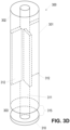
- FIG. 3D illustrates an alternative embodiment incorporating elongated support trusses 312 spaced at radial locations positioned at least substantially equally around the interior of the hollow tubular body 301.
- a single elongated support truss 312 may be positioned at each radial position within the interior of the hollow tubular body 301.
- each of the elongated support trusses 312 may extend between an upper open end of the hollow tubular body 301 to a lower open end of the hollow tubular body 301.
- the elongated support trusses 312 at each radial location may extend along only a portion of a length of the hollow tubular body 312.
- the lower deflector 310 may be detachably secured to the support rod 311 (e.g., via a threaded interface), thereby allowing different diameter lower deflectors 310 to be secured onto an end of the nozzle 300 to accommodate different electrochemical cell sizes, to accommodate different desired inner diameter AD 2 sizes of the first anode portion 18a, to accommodate different anode material viscosities, and/or the like.
- the support rod 311 extends at least partially along the length of the hollow tubular body 301 and supports the lower deflector 310 at a distance away from the open lower end 303 of the hollow tubular body 301 to define an annular gap 315 between the deflection surface of the lower deflector 310 and the open lower end 303 of the hollow tubular body 301.
- Electrode material e.g., anode material
- passed through the nozzle 300 move along the length of the hollow interior body 301 from the open upper end 302 to the open lower end 303 and is deflected out of the nozzle 300 through the annular gap 315.
- the annular gap 315 has a height between the open lower end 303 of the hollow tubular body 303 and the lowest point of the deflection surface of the lower deflector 310 that is optimized for providing electrode material into the electrochemical cell as the nozzle 300 is moved so as to form a structurally stable first portion 18a of the first electrode while still enabling a smooth flow of electrode material through the nozzle 300.
- the height of the annular gap 315 may be adjustable to enable optimization of the height of the annular gap 315 during use.
- the annular gap 315 has a height of between about 0.080" to about 0.125", such as between about 0.090" to about 0.124.”
- the height of the annular gap 135 may be adjusted to adjust the pressure and/or flow rate of the electrode material being provided to form the first portion 18a, which may impact the amount of settling of the electrode material of the first portion 18a after providing the same to the electrochemical cell.
- the nozzle 300 may have an associated linear actuator configured to move the nozzle 300 at least substantially linearly (e.g., vertically within the electrochemical cell 1 as electrode material is passed through the nozzle 300.
- the nozzle 300 may be initially placed such that a bottom surface of the lower deflector 310 is contacting or at least proximate a bottom surface of the interior opening of the electrochemical cell 1.
- electrode material e.g., anode material
- the nozzle 300 is retracted upward while electrode material is continually passed through the nozzle 300 and extruded against the sidewalls of the separator 14.
- the sidewalls of the lower deflector 310 form an interior surface of the first portion 18a of the first electrode that surrounds an interior opening of the first portion 18a of the first electrode (e.g., anode) that may be filled with the second portion 18b (and/or additional portions) of the first electrode (e.g., anode) with an at least substantially simultaneous or consecutive processing step as discussed herein.
- the speed at which the nozzle 300 is retracted from the interior of the electrochemical cell may be optimized to as to ensure the electrode material of the first portion 18a sets sufficiently to avoid excessive settling during movement of the nozzle 300, which may lead to unpredictable or excessive settling of the first anode portion 18a.
- the support rod 311 and lower deflector 310 define an interior conduit 313 through which an additional electrode material (also referred to herein as a second electrode material, which may be embodied as, for example, a second anode material) corresponding to the second portion 18b may be extruded.
- an additional electrode material also referred to herein as a second electrode material, which may be embodied as, for example, a second anode material
- the first portion 18a and second portion 18b of the first electrode may be formed at least substantially simultaneously, with a single formation tool.
- the electrode material (e.g., anode material) of the first portion 18a may be provided between the support rod 311 and the hollow tubular body 301 while the second electrode material (e.g., second anode material) of the second portion 18b flows through the hollow interior of the support rod 311.
- the second electrode material e.g., second anode material
- Such embodiments may increase production speeds associated with generating multi-part inner electrodes (e.g., multi-part anodes).
- providing the second portion 18b of the electrode simultaneously with the first portion 18a of the electrode may inhibit settling of the first portion 18a, as the second portion 18b is present to counteract settling of the first portion 18a.
- the one or more portions of the anode may be extruded to form the first electrode within the electrochemical cell.
- various portions of the first electrode 18 may be co-extruded (e.g., by simultaneously or successively extruding separate portions of the first electrode 18 via a nozzle 300 configured in accordance with the illustration of FIG. 5 ), extruded in series (extruding a first portion 18a of the first electrode 18 utilizing a nozzle 300 configured in accordance with FIGS.
- the nozzle 300 is first inserted into the opening formed by the second electrode 12 and the separator 14, to a first position in which a bottom surface of the lower deflector 310 is positioned against a bottom surface of the opening (e.g., a bottom wall of the separator 14).
- the electrode material of the first portion 18a of the first electrode 18 e.g., anode material utilized to form the first portion of the anode
- the hollow tubular body 301 of the nozzle 300 is passed through the hollow tubular body 301 of the nozzle 300 and out the annular opening 15.
- the nozzle 300 is retracted (e.g., slowly retracted) out of the electrochemical cell 1 at a rate determined based at least in part on the rate of extrusion (e.g., the fluid pressure and/or flowrate) of the electrode material through the nozzle 300, as illustrated in FIG. 4 .
- the rate of extrusion e.g., the fluid pressure and/or flowrate
- the level of the electrode material within the electrochemical cell 1 rises (and an upper surface of the first portion 18a of the first electrode (e.g., anode) continues to rise).
- the rate of retraction of the nozzle 300 is maintained such that the rising upper surface of the first portion 18a of the first electrode remains above the bottom surface of the lower deflector 310.
- the rising upper surface of the first portion 18a remains aligned with a sidewall of the lower deflector 310 or the rising upper surface of the upper portion 18a remains above a deflection surface of the lower deflector 310.
- the first portion 18a maintains a tubular shape having an open interior as the nozzle 300 (and the lower deflector 310) is retracted.
- a separate nozzle may be utilized to fill the internal opening of the first portion 18a with the second electrode material of the second portion 18b.
- the second electrode material of the second portion 18b may be provided via conduit 313, as the nozzle 300 is retracted, thereby filling the internal opening of the first portion 18a to form the second portion 18b of the electrode at least substantially simultaneously with the formation of the first portion 18a.
- the zinc and solid zinc oxide powders, and other optional powders other than the gelling agent are combined and mixed.
- the zinc and solid zinc oxide powders may be mixed in separate batches corresponding to various portion of the first electrode 18 (e.g., the anode).
- first zinc and zinc oxide powders may be mixed to form a first batch and second zinc and zinc oxide powers may be mixed to form a second batch (e.g., comprising a zinc powder having a different average zinc particle size than the zinc powder of the first batch).
- a surfactant may be introduced into the mixture containing the zinc and solid zinc oxide (e.g., the surfactant may be introduced into each of the various batches).
- a pre-gel comprising alkaline electrolyte, soluble zinc oxide and gelling agent, and optionally other liquid components, may be introduced to the surfactant, zinc and solid zinc oxide mixture(s) which are further mixed to obtain a substantially homogenous mixture (e.g., homogeneous within each batch) before addition to the cell.
- one or more component of each batch may be varied to provide a desired anode characteristics difference between each batch (e.g., providing a different quantity of surfactant; providing a different zinc grade; providing a different zinc oxide quantity; and/or the like).
- the solid zinc oxide is pre-dispersed in a negative electrode pre-gel comprising the alkaline electrolyte, gelling agent, soluble zinc oxide and other desired liquids, and blended, such as for about 15 minutes.
- a negative electrode pre-gel comprising the alkaline electrolyte, gelling agent, soluble zinc oxide and other desired liquids, and blended, such as for about 15 minutes.
- multiple batches may be provided, each comprising the solid zinc oxide, the alkaline electrolyte, gelling agent, soluble zinc oxide and other desired liquids.
- each batch may comprise a different composition of the combined components, as mentioned above.
- the solid zinc and surfactant are then added and each batch of the first electrode composition is blended for an additional period of time, such as about 20 minutes.
- the amount of gelled electrolyte utilized in each batch of the first electrode composition is generally from about 25 to about 35 weight percent.
- the amount of gelled electrolyte may be about 32 weight percent based on the total weight of each batch of first electrode composition.
- Volume percent of the gelled electrolyte may, in certain embodiments, be about 70% based on the total volume of the first electrode.
- an additional quantity of an aqueous solution of alkaline metal hydroxide i.e., "free electrolyte" may also be added to the cell during the manufacturing process.
- the free electrolyte may be incorporated into the cell by disposing it into the cavity defined by the positive electrode or negative electrode, or combinations thereof. In one embodiment, free electrolyte is added both prior to addition of the negative electrode mixture as well as after addition. In one embodiment, about 0.97 grams of 29 weight percent KOH solution is added to an LR6 type cell as free electrolyte, with about 0.87 grams added to the separator lined cavity before the negative electrode is added. As discussed herein, the free electrolyte added prior to addition of the negative electrode may comprise a surfactant composition that is later absorbed by the negative electrode, thereby forming a surfactant concentration gradient within at least a portion of the negative electrode. The remaining portion of the 29 weight percent KOH solution is injected into the separator lined cavity after the negative electrode has been inserted.
- Second electrode 12 also referred to herein as the positive electrode or cathode, may include manganese dioxide as the electrochemically active material.
- Manganese dioxide is present in an amount generally from about 80 to about 86 weight percent, such as from about 81 to 85 percent by weight based on the total weight of the positive electrode, i.e., manganese dioxide, conductive material, positive electrode electrolyte and additives such as barium sulfate.
- Manganese dioxide is commercially available as natural manganese dioxide (NMD), chemical manganese dioxide (CMD), or electrolytic manganese dioxide (EMD).
- the preferred manganese dioxide for use in a cell is EMD. Suppliers of EMD include Tronox Ltd.
- the positive electrode is formed by combining and mixing desired components of the electrode followed by dispensing a quantity of the mixture into the open end of the container and then using a ram to mold the mixture into a solid tubular configuration that defines a cavity within the container in which the separator 14 and first electrode 18 are later disposed.
- Second electrode 12 has a ledge 30 and an interior surface 32 as illustrated in FIG. 1 .
- the positive electrode may be formed by pre-forming a plurality of rings from the mixture comprising manganese dioxide and then inserting the rings into the container to form the tubular-shaped second electrode.
- the cell shown in FIG. 1 would typically include 3 or 4 rings.
- the positive electrode can include other components such as a conductive material, for example graphite, that when mixed with the manganese dioxide provides an electrically conductive matrix substantially throughout the positive electrode.
- Conductive material can be natural, i.e., mined, or synthetic, i.e., manufactured.
- the cells include a positive electrode having an active material or oxide to carbon ratio (O:C ratio) that ranges from about 12 to about 14. Too high of an oxide to carbon ratio decreases the container to cathode resistance, which affects the overall cell resistance and can have a potential effect on high rate tests, such as the DSC test, or higher cut-off voltages.
- the graphite can be expanded or non-expanded.
- Graphite Suppliers of graphite for use in alkaline batteries include Imerys Graphite & Carbon in Bironico, Switzerland and Superior Graphite in Chicago, Illinois. Conductive material is present generally in an amount from about 5 to about 10 weight percent based on the total weight of the positive electrode. Too much graphite can reduce manganese dioxide input, and thus cell capacity; too little graphite can increase container to cathode contact resistance and/or bulk cathode resistance.
- An example of an additional additive is barium sulfate (BaSO 4 ), which is commercially available from Bario E. Derivati S.p.A. of Massa, Italy. The barium sulfate is present in an amount generally from about 1 to about 2 weight percent based on the total weight of the positive electrode.
- Other additives can include, for example, barium acetate, titanium dioxide, binders such as coathylene, and calcium stearate.
- the positive electrode component such as the manganese dioxide, conductive material, and barium sulfate are mixed together to form a homogeneous mixture.
- an alkaline electrolyte solution such as from about 37% to about 40% KOH solution, is evenly dispersed into the mixture thereby insuring a uniform distribution of the solution throughout the positive electrode materials.
- the mixture is then added to the container and molded utilizing a ram. Moisture within the container and positive electrode mix before and after molding, and components of the mix may be optimized to allow quality positive electrodes to be molded.
- Separator 14 is provided in order to separate first electrode 18 from second electrode 12. Separator 14 maintains a physical dielectric separation of the positive electrode's electrochemically active material from the electrochemically active material of the negative electrode and allows for transport of ions between the electrode materials. In addition, the separator acts as a wicking medium for the electrolyte and as a collar that prevents fragmented portions of the negative electrode from contacting the top of the positive electrode. Separator 14 can be a layered ion permeable, non-woven fibrous fabric. A typical separator usually includes two or more layers of paper.
- Conventional separators are usually formed either by pre-forming the separator material into a cup-shaped basket that is subsequently inserted under the cavity defined by second electrode 12 and closed end 24 and any positive electrode material thereon, or forming a basket during cell assembly by inserting two rectangular sheets of separator into the cavity with the material angularly rotated 90° relative to each other.
- Conventional pre-formed separators are typically made up of a sheet of non-woven fabric rolled into a cylindrical shape that conforms to the inside walls of the second electrode and has a closed bottom end.
- the characteristics of the first electrode may be modified to encourage a lower discharge resistance within first electrode portions closer to the central current collector (and away from the separator), which may increase the quantity of zinc available near the separator after certain depth of the discharge during moderate- and high-rate discharge of the cell.
- different surfactant types may be provided in portions of the anode proximate the separator and proximate the current collector to spread out the current distribution so that a higher percentage of the anode active materials within the anode participate in the discharge reactions; a larger average particle size of anode active material may be disposed proximate the separator (e.g., to avoid the complete consumption of the zinc near the separator during moderate and high rate discharge); and/or the like.
- the portions of the anode closer to the current collector may be modified to have decreased gassing characteristics, thereby reducing undesirable gassing when the anode is highly discharged.
Landscapes
- Engineering & Computer Science (AREA)
- Manufacturing & Machinery (AREA)
- Chemical & Material Sciences (AREA)
- Chemical Kinetics & Catalysis (AREA)
- Electrochemistry (AREA)
- General Chemical & Material Sciences (AREA)
- Primary Cells (AREA)
- Secondary Cells (AREA)
Claims (14)
- Düse (300) zum Liefern eines Elektrodenmaterials in eine elektrochemische Zelle (1), wobei die Düse Folgendes umfasst:einen hohlen röhrenförmigen Körper (301), der sich zwischen einem offenen oberen Ende (302) und einem offenen unteren Ende (303) erstreckt,einen unteren Abweiser (310), der von dem offenen unteren Ende des hohlen röhrenförmigen Körpers beabstandet ist und eine ringförmige Öffnung (315) zwischen einer Ablenkfläche des unteren Abweisers und dem offenen unteren Ende des hohlen röhrenförmigen Körpers bildet, undeine Stützstange (311), die den unteren Abweiser mit dem hohlen röhrenförmigen Körper verbindet, wobei die Stützstange innerhalb eines Inneren des hohlen röhrenförmigen Körpers durch einen oder mehrere Stützträger (312) aufgehängt ist.
- Düse nach Anspruch 1, wobei die Stützstange und der untere Abweiser eine Leitung (313) definieren, die sich durch dieselben erstreckt.
- Düse nach Anspruch 1, wobei der untere Abweiser einen Durchmesser, größer als ein äußerer zweiter Durchmesser des hohlen röhrenförmigen Körpers, aufweist.
- Düse nach Anspruch 1, wobei die Ablenkfläche als eine konkave Fläche ausgeführt ist.
- Düse nach Anspruch 1, wobei die ringförmige Öffnung einstellbar ist.
- Düse nach Anspruch 1, wobei die ringförmige Öffnung eine Höhe zwischen etwa 0,09" und etwa 0,125" aufweist.
- Düse nach Anspruch 1, wobei der Abweiser einen Durchmesser zwischen etwa 0,24" und etwa 0,275" aufweist.
- Düse nach Anspruch 1, wobei der eine oder die mehreren Stützträger an radialen Positionen beabstandet sind, die mindestens im Wesentlichen gleichmäßig um ein Inneres des hohlen röhrenförmigen Körpers verteilt sind.
- Düse nach Anspruch 8, wobei der eine oder die mehreren Stützträger eine Vielzahl von Stützträgern an jeder radialen Position umfassen.
- Verfahren zum Bilden einer Elektrode (18) einer elektrochemischen Zelle (1) unter Verwendung einer Düse (300), wobei die Düse Folgendes umfasst:einen hohlen röhrenförmigen Körper (301), der sich zwischen einem offenen oberen Ende (302) und einem offenen unteren Ende (303) erstreckt,einen unteren Abweiser (310), der von dem offenen unteren Ende des hohlen röhrenförmigen Körpers beabstandet ist und eine ringförmige Öffnung (315) zwischen einer Ablenkfläche des unteren Abweisers und dem offenen unteren Ende des hohlen röhrenförmigen Körpers bildet, undeine Stützstange (311), die den unteren Abweiser mit dem hohlen röhrenförmigen Körper verbindet, wobei die Stützstange innerhalb eines Inneren des hohlen röhrenförmigen Körpers durch einen oder mehrere Stützträger (312) aufgehängt ist,wobei das Verfahren Folgendes umfasst:Positionieren der Düse innerhalb einer mittigen Öffnung der elektrochemischen Zelle,Zurückziehen der Düse aus der mittigen Öffnung der elektrochemischen Zelle, während fortlaufend ein erstes Anodenmaterial durch die ringförmige Öffnung extrudiert wird, die nahe dem unteren Ende der Düse befindlich ist, um einen ersten Anodenabschnitt (18a) zu bilden, der eine mittige Öffnung aufweist, undExtrudieren eines zweiten Anodenmaterials in die mittige Öffnung des ersten Anodenabschnitts.
- Verfahren nach Anspruch 10, wobei das Extrudieren des zweiten Anodenmaterials in die mittige Öffnung des ersten Anodenabschnitts das Extrudieren des zweiten Anodenmaterials durch eine mittige Leitung (313) innerhalb der Düse umfasst, während die Düse aus der mittigen Öffnung der elektrochemischen Zelle zurückgezogen wird.
- Verfahren nach Anspruch 10 oder Anspruch 11, wobei das Extrudieren des ersten Anodenmaterials durch die ringförmige Öffnung Folgendes umfasst:
Extrudieren des ersten Anodenmaterials entlang einer Länge des hohlen röhrenförmigen Körpers von dem offenen oberen Ende bis zu dem offenen unteren Ende und gegen die Ablenkfläche des unteren Abweisers, wobei die Ablenkfläche das erste Anodenmaterial durch die ringförmige Öffnung umleitet. - Verfahren nach einem der Ansprüche 10 bis 12, das ferner das Einstellen einer Höhe der ringförmigen Öffnung umfasst.
- Verfahren nach einem der Ansprüche 10 bis 13, wobei das Extrudieren des zweiten Anodenmaterials in die mittige Öffnung des ersten Anodenabschnitts das Extrudieren des zweiten Anodenmaterials in die mittige Öffnung des ersten Anodenabschnitts nach dem Zurückziehen der Düse aus der mittigen Öffnung des ersten Anodenabschnitts umfasst.
Applications Claiming Priority (3)
| Application Number | Priority Date | Filing Date | Title |
|---|---|---|---|
| US202062964374P | 2020-01-22 | 2020-01-22 | |
| US17/144,672 US11502284B2 (en) | 2020-01-22 | 2021-01-08 | Systems and methods for generating an electrochemical cell having a multi-part anode |
| PCT/US2021/013151 WO2021150402A1 (en) | 2020-01-22 | 2021-01-13 | Systems and methods for generating an electrochemical cell having a multi-part anode |
Publications (2)
| Publication Number | Publication Date |
|---|---|
| EP4094308A1 EP4094308A1 (de) | 2022-11-30 |
| EP4094308B1 true EP4094308B1 (de) | 2023-11-22 |
Family
ID=76858261
Family Applications (1)
| Application Number | Title | Priority Date | Filing Date |
|---|---|---|---|
| EP21704347.0A Active EP4094308B1 (de) | 2020-01-22 | 2021-01-13 | Systeme und verfahren zur erzeugung einer elektrochemischen zelle mit einer mehrteiligen anode |
Country Status (5)
| Country | Link |
|---|---|
| US (1) | US11502284B2 (de) |
| EP (1) | EP4094308B1 (de) |
| JP (1) | JP7449392B2 (de) |
| CN (1) | CN115315829B (de) |
| WO (1) | WO2021150402A1 (de) |
Families Citing this family (3)
| Publication number | Priority date | Publication date | Assignee | Title |
|---|---|---|---|---|
| CA3074866C (en) | 2017-09-15 | 2023-03-28 | Energizer Brands, Llc | Separator for alkaline cells |
| US11211615B2 (en) | 2018-09-28 | 2021-12-28 | Energizer Brands, Llc | Alkaline battery having a dual-anode |
| US11450847B2 (en) | 2019-01-23 | 2022-09-20 | Energizer Brands, Llc | Alkaline electrochemical cells comprising increased zinc oxide levels |
Family Cites Families (24)
| Publication number | Priority date | Publication date | Assignee | Title |
|---|---|---|---|---|
| AU438685B2 (en) | 1971-04-30 | 1973-07-31 | Buzova, Zoya Mikhailovna | An arrangement for manufacture ofa primary cell electrode |
| JPS56126267A (en) * | 1980-03-05 | 1981-10-03 | Matsushita Electric Ind Co Ltd | Gel injection method |
| JPH07109761B2 (ja) * | 1982-11-25 | 1995-11-22 | 松下電器産業株式会社 | 円筒形電池への注液方法 |
| US5401590A (en) | 1992-12-07 | 1995-03-28 | Duracell Inc. | Additives for electrochemical cells having zinc anodes |
| JP3366536B2 (ja) * | 1996-11-11 | 2003-01-14 | 東芝電池株式会社 | ゲル状負極作用物質の注入装置 |
| US5962163A (en) | 1997-08-27 | 1999-10-05 | Eveready Battery Company, Inc. | Alkaline cell with gel type anode having centrally disposed gelling agent absorbent |
| JPH11224674A (ja) * | 1998-02-05 | 1999-08-17 | Toshiba Battery Co Ltd | ゲル状負極作用物質の充填方法および充填装置 |
| US6074781A (en) * | 1998-06-26 | 2000-06-13 | Eveready Battery Company, Inc. | Electrochemical cell having increased anode-to-cathode interface area |
| US6207322B1 (en) | 1998-11-16 | 2001-03-27 | Duracell Inc | Alkaline cell with semisolid cathode |
| US6326102B1 (en) * | 1998-11-24 | 2001-12-04 | Eveready Battery Company, Inc. | High rate electrochemical cell with increased anode-to-cathode interface surface area |
| JP2003217600A (ja) * | 2002-01-17 | 2003-07-31 | Toshiba Battery Co Ltd | ゲル状電極作用物質の充填装置 |
| US7226696B2 (en) | 2002-02-27 | 2007-06-05 | Rayovac Corporation | Alkaline cell with performance enhancing additives |
| US20070248879A1 (en) | 2002-08-28 | 2007-10-25 | Durkot Richard E | Alkaline battery including nickel oxyhydroxide cathode and zinc anode |
| US7147678B2 (en) | 2003-07-03 | 2006-12-12 | The Gillette Company | Alkaline cell with improved anode |
| CN1331266C (zh) | 2004-04-30 | 2007-08-08 | 比亚迪股份有限公司 | 一种碱性蓄电池及其制备方法 |
| EP1715536A3 (de) | 2005-04-20 | 2007-10-10 | ReVolt Technology AS | Zinkelektrode mit einem organischen Geliermittel und einem organischen Bindemittel. |
| JP2007048623A (ja) * | 2005-08-10 | 2007-02-22 | Fdk Energy Co Ltd | アルカリ乾電池 |
| US8586244B2 (en) | 2007-04-02 | 2013-11-19 | Eveready Battery Co., Inc. | Alkaline electrochemical cell having a negative electrode with solid zinc oxide and a surfactant |
| JP2009164079A (ja) | 2008-01-10 | 2009-07-23 | Panasonic Corp | アルカリマンガン電池の製造方法およびアルカリマンガン電池 |
| US8323835B2 (en) | 2008-10-01 | 2012-12-04 | The Gillette Company | Batteries having multiple anode portions |
| AU2016206976B2 (en) | 2015-01-16 | 2019-12-19 | Energizer Brands, Llc | Alkaline cell with improved reliability and discharge performance |
| WO2017070340A1 (en) | 2015-10-21 | 2017-04-27 | Research Foundation Of The City University Of New York | Additive for increasing lifespan of rechargeable zinc-anode batteries |
| US11322752B2 (en) | 2017-03-10 | 2022-05-03 | Energizer Brands, Llc | Anode cross-sectional characteristic gradient |
| US11211615B2 (en) | 2018-09-28 | 2021-12-28 | Energizer Brands, Llc | Alkaline battery having a dual-anode |
-
2021
- 2021-01-08 US US17/144,672 patent/US11502284B2/en active Active
- 2021-01-13 CN CN202180023232.7A patent/CN115315829B/zh active Active
- 2021-01-13 JP JP2022544704A patent/JP7449392B2/ja active Active
- 2021-01-13 EP EP21704347.0A patent/EP4094308B1/de active Active
- 2021-01-13 WO PCT/US2021/013151 patent/WO2021150402A1/en not_active Ceased
Also Published As
| Publication number | Publication date |
|---|---|
| WO2021150402A1 (en) | 2021-07-29 |
| CN115315829B (zh) | 2025-10-28 |
| CA3165631A1 (en) | 2021-07-29 |
| CN115315829A (zh) | 2022-11-08 |
| JP2023511202A (ja) | 2023-03-16 |
| JP7449392B2 (ja) | 2024-03-13 |
| US11502284B2 (en) | 2022-11-15 |
| EP4094308A1 (de) | 2022-11-30 |
| US20210226191A1 (en) | 2021-07-22 |
Similar Documents
| Publication | Publication Date | Title |
|---|---|---|
| US11677082B2 (en) | Alkaline battery having a dual-anode | |
| EP2132809B1 (de) | Elektrochemische alkalizelle | |
| US11322752B2 (en) | Anode cross-sectional characteristic gradient | |
| EP4094308B1 (de) | Systeme und verfahren zur erzeugung einer elektrochemischen zelle mit einer mehrteiligen anode | |
| US20060046135A1 (en) | Alkaline battery with MnO2/NiOOH active material | |
| EP3540837B1 (de) | Langkettige tenside zur verbesserung der batterieeigenschaften | |
| CA3165631C (en) | Systems and methods for generating an electrochemical cell having a multi-part anode | |
| US11133499B2 (en) | Substituted ramsdellite manganese dioxides in an alkaline electrochemical cell | |
| US11081763B2 (en) | Current interrupt for electrochemical cells | |
| US20240162590A1 (en) | Alkaline electrodes with electrolyte reservoirs | |
| WO2024129858A1 (en) | Electrode stack for alkaline electrochemical cells | |
| HK1138435B (en) | Alkaline electrochemical cell |
Legal Events
| Date | Code | Title | Description |
|---|---|---|---|
| STAA | Information on the status of an ep patent application or granted ep patent |
Free format text: STATUS: UNKNOWN |
|
| STAA | Information on the status of an ep patent application or granted ep patent |
Free format text: STATUS: THE INTERNATIONAL PUBLICATION HAS BEEN MADE |
|
| PUAI | Public reference made under article 153(3) epc to a published international application that has entered the european phase |
Free format text: ORIGINAL CODE: 0009012 |
|
| STAA | Information on the status of an ep patent application or granted ep patent |
Free format text: STATUS: REQUEST FOR EXAMINATION WAS MADE |
|
| 17P | Request for examination filed |
Effective date: 20220803 |
|
| AK | Designated contracting states |
Kind code of ref document: A1 Designated state(s): AL AT BE BG CH CY CZ DE DK EE ES FI FR GB GR HR HU IE IS IT LI LT LU LV MC MK MT NL NO PL PT RO RS SE SI SK SM TR |
|
| DAV | Request for validation of the european patent (deleted) | ||
| DAX | Request for extension of the european patent (deleted) | ||
| GRAP | Despatch of communication of intention to grant a patent |
Free format text: ORIGINAL CODE: EPIDOSNIGR1 |
|
| STAA | Information on the status of an ep patent application or granted ep patent |
Free format text: STATUS: GRANT OF PATENT IS INTENDED |
|
| RIC1 | Information provided on ipc code assigned before grant |
Ipc: H01M 4/24 20060101ALN20230430BHEP Ipc: H01M 6/06 20060101ALN20230430BHEP Ipc: H01M 4/42 20060101ALN20230430BHEP Ipc: H01M 6/04 20060101ALN20230430BHEP Ipc: B05B 12/14 20060101ALI20230430BHEP Ipc: B05B 1/26 20060101ALI20230430BHEP Ipc: H01M 4/12 20060101ALI20230430BHEP Ipc: H01M 4/04 20060101AFI20230430BHEP |
|
| INTG | Intention to grant announced |
Effective date: 20230605 |
|
| GRAS | Grant fee paid |
Free format text: ORIGINAL CODE: EPIDOSNIGR3 |
|
| GRAA | (expected) grant |
Free format text: ORIGINAL CODE: 0009210 |
|
| STAA | Information on the status of an ep patent application or granted ep patent |
Free format text: STATUS: THE PATENT HAS BEEN GRANTED |
|
| P01 | Opt-out of the competence of the unified patent court (upc) registered |
Effective date: 20230922 |
|
| AK | Designated contracting states |
Kind code of ref document: B1 Designated state(s): AL AT BE BG CH CY CZ DE DK EE ES FI FR GB GR HR HU IE IS IT LI LT LU LV MC MK MT NL NO PL PT RO RS SE SI SK SM TR |
|
| REG | Reference to a national code |
Ref country code: GB Ref legal event code: FG4D |
|
| REG | Reference to a national code |
Ref country code: CH Ref legal event code: EP Ref country code: DE Ref legal event code: R096 Ref document number: 602021007064 Country of ref document: DE |
|
| REG | Reference to a national code |
Ref country code: IE Ref legal event code: FG4D |
|
| REG | Reference to a national code |
Ref country code: LT Ref legal event code: MG9D |
|
| REG | Reference to a national code |
Ref country code: NL Ref legal event code: MP Effective date: 20231122 |
|
| PG25 | Lapsed in a contracting state [announced via postgrant information from national office to epo] |
Ref country code: GR Free format text: LAPSE BECAUSE OF FAILURE TO SUBMIT A TRANSLATION OF THE DESCRIPTION OR TO PAY THE FEE WITHIN THE PRESCRIBED TIME-LIMIT Effective date: 20240223 |
|
| PG25 | Lapsed in a contracting state [announced via postgrant information from national office to epo] |
Ref country code: IS Free format text: LAPSE BECAUSE OF FAILURE TO SUBMIT A TRANSLATION OF THE DESCRIPTION OR TO PAY THE FEE WITHIN THE PRESCRIBED TIME-LIMIT Effective date: 20240322 |
|
| PG25 | Lapsed in a contracting state [announced via postgrant information from national office to epo] |
Ref country code: LT Free format text: LAPSE BECAUSE OF FAILURE TO SUBMIT A TRANSLATION OF THE DESCRIPTION OR TO PAY THE FEE WITHIN THE PRESCRIBED TIME-LIMIT Effective date: 20231122 |
|
| REG | Reference to a national code |
Ref country code: AT Ref legal event code: MK05 Ref document number: 1634666 Country of ref document: AT Kind code of ref document: T Effective date: 20231122 |
|
| PG25 | Lapsed in a contracting state [announced via postgrant information from national office to epo] |
Ref country code: NL Free format text: LAPSE BECAUSE OF FAILURE TO SUBMIT A TRANSLATION OF THE DESCRIPTION OR TO PAY THE FEE WITHIN THE PRESCRIBED TIME-LIMIT Effective date: 20231122 |
|
| PG25 | Lapsed in a contracting state [announced via postgrant information from national office to epo] |
Ref country code: AT Free format text: LAPSE BECAUSE OF FAILURE TO SUBMIT A TRANSLATION OF THE DESCRIPTION OR TO PAY THE FEE WITHIN THE PRESCRIBED TIME-LIMIT Effective date: 20231122 |
|
| PG25 | Lapsed in a contracting state [announced via postgrant information from national office to epo] |
Ref country code: ES Free format text: LAPSE BECAUSE OF FAILURE TO SUBMIT A TRANSLATION OF THE DESCRIPTION OR TO PAY THE FEE WITHIN THE PRESCRIBED TIME-LIMIT Effective date: 20231122 |
|
| PG25 | Lapsed in a contracting state [announced via postgrant information from national office to epo] |
Ref country code: NL Free format text: LAPSE BECAUSE OF FAILURE TO SUBMIT A TRANSLATION OF THE DESCRIPTION OR TO PAY THE FEE WITHIN THE PRESCRIBED TIME-LIMIT Effective date: 20231122 Ref country code: LT Free format text: LAPSE BECAUSE OF FAILURE TO SUBMIT A TRANSLATION OF THE DESCRIPTION OR TO PAY THE FEE WITHIN THE PRESCRIBED TIME-LIMIT Effective date: 20231122 Ref country code: IS Free format text: LAPSE BECAUSE OF FAILURE TO SUBMIT A TRANSLATION OF THE DESCRIPTION OR TO PAY THE FEE WITHIN THE PRESCRIBED TIME-LIMIT Effective date: 20240322 Ref country code: GR Free format text: LAPSE BECAUSE OF FAILURE TO SUBMIT A TRANSLATION OF THE DESCRIPTION OR TO PAY THE FEE WITHIN THE PRESCRIBED TIME-LIMIT Effective date: 20240223 Ref country code: ES Free format text: LAPSE BECAUSE OF FAILURE TO SUBMIT A TRANSLATION OF THE DESCRIPTION OR TO PAY THE FEE WITHIN THE PRESCRIBED TIME-LIMIT Effective date: 20231122 Ref country code: BG Free format text: LAPSE BECAUSE OF FAILURE TO SUBMIT A TRANSLATION OF THE DESCRIPTION OR TO PAY THE FEE WITHIN THE PRESCRIBED TIME-LIMIT Effective date: 20240222 Ref country code: AT Free format text: LAPSE BECAUSE OF FAILURE TO SUBMIT A TRANSLATION OF THE DESCRIPTION OR TO PAY THE FEE WITHIN THE PRESCRIBED TIME-LIMIT Effective date: 20231122 Ref country code: PT Free format text: LAPSE BECAUSE OF FAILURE TO SUBMIT A TRANSLATION OF THE DESCRIPTION OR TO PAY THE FEE WITHIN THE PRESCRIBED TIME-LIMIT Effective date: 20240322 |
|
| PG25 | Lapsed in a contracting state [announced via postgrant information from national office to epo] |
Ref country code: SE Free format text: LAPSE BECAUSE OF FAILURE TO SUBMIT A TRANSLATION OF THE DESCRIPTION OR TO PAY THE FEE WITHIN THE PRESCRIBED TIME-LIMIT Effective date: 20231122 Ref country code: RS Free format text: LAPSE BECAUSE OF FAILURE TO SUBMIT A TRANSLATION OF THE DESCRIPTION OR TO PAY THE FEE WITHIN THE PRESCRIBED TIME-LIMIT Effective date: 20231122 Ref country code: PL Free format text: LAPSE BECAUSE OF FAILURE TO SUBMIT A TRANSLATION OF THE DESCRIPTION OR TO PAY THE FEE WITHIN THE PRESCRIBED TIME-LIMIT Effective date: 20231122 Ref country code: NO Free format text: LAPSE BECAUSE OF FAILURE TO SUBMIT A TRANSLATION OF THE DESCRIPTION OR TO PAY THE FEE WITHIN THE PRESCRIBED TIME-LIMIT Effective date: 20240222 Ref country code: LV Free format text: LAPSE BECAUSE OF FAILURE TO SUBMIT A TRANSLATION OF THE DESCRIPTION OR TO PAY THE FEE WITHIN THE PRESCRIBED TIME-LIMIT Effective date: 20231122 Ref country code: HR Free format text: LAPSE BECAUSE OF FAILURE TO SUBMIT A TRANSLATION OF THE DESCRIPTION OR TO PAY THE FEE WITHIN THE PRESCRIBED TIME-LIMIT Effective date: 20231122 |
|
| PG25 | Lapsed in a contracting state [announced via postgrant information from national office to epo] |
Ref country code: DK Free format text: LAPSE BECAUSE OF FAILURE TO SUBMIT A TRANSLATION OF THE DESCRIPTION OR TO PAY THE FEE WITHIN THE PRESCRIBED TIME-LIMIT Effective date: 20231122 |
|
| PG25 | Lapsed in a contracting state [announced via postgrant information from national office to epo] |
Ref country code: CZ Free format text: LAPSE BECAUSE OF FAILURE TO SUBMIT A TRANSLATION OF THE DESCRIPTION OR TO PAY THE FEE WITHIN THE PRESCRIBED TIME-LIMIT Effective date: 20231122 |
|
| PG25 | Lapsed in a contracting state [announced via postgrant information from national office to epo] |
Ref country code: SK Free format text: LAPSE BECAUSE OF FAILURE TO SUBMIT A TRANSLATION OF THE DESCRIPTION OR TO PAY THE FEE WITHIN THE PRESCRIBED TIME-LIMIT Effective date: 20231122 |
|
| PG25 | Lapsed in a contracting state [announced via postgrant information from national office to epo] |
Ref country code: SM Free format text: LAPSE BECAUSE OF FAILURE TO SUBMIT A TRANSLATION OF THE DESCRIPTION OR TO PAY THE FEE WITHIN THE PRESCRIBED TIME-LIMIT Effective date: 20231122 Ref country code: SK Free format text: LAPSE BECAUSE OF FAILURE TO SUBMIT A TRANSLATION OF THE DESCRIPTION OR TO PAY THE FEE WITHIN THE PRESCRIBED TIME-LIMIT Effective date: 20231122 Ref country code: RO Free format text: LAPSE BECAUSE OF FAILURE TO SUBMIT A TRANSLATION OF THE DESCRIPTION OR TO PAY THE FEE WITHIN THE PRESCRIBED TIME-LIMIT Effective date: 20231122 Ref country code: EE Free format text: LAPSE BECAUSE OF FAILURE TO SUBMIT A TRANSLATION OF THE DESCRIPTION OR TO PAY THE FEE WITHIN THE PRESCRIBED TIME-LIMIT Effective date: 20231122 Ref country code: DK Free format text: LAPSE BECAUSE OF FAILURE TO SUBMIT A TRANSLATION OF THE DESCRIPTION OR TO PAY THE FEE WITHIN THE PRESCRIBED TIME-LIMIT Effective date: 20231122 Ref country code: CZ Free format text: LAPSE BECAUSE OF FAILURE TO SUBMIT A TRANSLATION OF THE DESCRIPTION OR TO PAY THE FEE WITHIN THE PRESCRIBED TIME-LIMIT Effective date: 20231122 |
|
| REG | Reference to a national code |
Ref country code: DE Ref legal event code: R097 Ref document number: 602021007064 Country of ref document: DE |
|
| PG25 | Lapsed in a contracting state [announced via postgrant information from national office to epo] |
Ref country code: MC Free format text: LAPSE BECAUSE OF FAILURE TO SUBMIT A TRANSLATION OF THE DESCRIPTION OR TO PAY THE FEE WITHIN THE PRESCRIBED TIME-LIMIT Effective date: 20231122 |
|
| PG25 | Lapsed in a contracting state [announced via postgrant information from national office to epo] |
Ref country code: MC Free format text: LAPSE BECAUSE OF FAILURE TO SUBMIT A TRANSLATION OF THE DESCRIPTION OR TO PAY THE FEE WITHIN THE PRESCRIBED TIME-LIMIT Effective date: 20231122 |
|
| REG | Reference to a national code |
Ref country code: CH Ref legal event code: PL |
|
| PG25 | Lapsed in a contracting state [announced via postgrant information from national office to epo] |
Ref country code: LU Free format text: LAPSE BECAUSE OF NON-PAYMENT OF DUE FEES Effective date: 20240113 |
|
| PLBE | No opposition filed within time limit |
Free format text: ORIGINAL CODE: 0009261 |
|
| STAA | Information on the status of an ep patent application or granted ep patent |
Free format text: STATUS: NO OPPOSITION FILED WITHIN TIME LIMIT |
|
| PG25 | Lapsed in a contracting state [announced via postgrant information from national office to epo] |
Ref country code: LU Free format text: LAPSE BECAUSE OF NON-PAYMENT OF DUE FEES Effective date: 20240113 |
|
| PG25 | Lapsed in a contracting state [announced via postgrant information from national office to epo] |
Ref country code: BE Free format text: LAPSE BECAUSE OF NON-PAYMENT OF DUE FEES Effective date: 20240131 |
|
| PG25 | Lapsed in a contracting state [announced via postgrant information from national office to epo] |
Ref country code: CH Free format text: LAPSE BECAUSE OF NON-PAYMENT OF DUE FEES Effective date: 20240131 |
|
| PG25 | Lapsed in a contracting state [announced via postgrant information from national office to epo] |
Ref country code: SI Free format text: LAPSE BECAUSE OF FAILURE TO SUBMIT A TRANSLATION OF THE DESCRIPTION OR TO PAY THE FEE WITHIN THE PRESCRIBED TIME-LIMIT Effective date: 20231122 |
|
| 26N | No opposition filed |
Effective date: 20240823 |
|
| PG25 | Lapsed in a contracting state [announced via postgrant information from national office to epo] |
Ref country code: SI Free format text: LAPSE BECAUSE OF FAILURE TO SUBMIT A TRANSLATION OF THE DESCRIPTION OR TO PAY THE FEE WITHIN THE PRESCRIBED TIME-LIMIT Effective date: 20231122 Ref country code: CH Free format text: LAPSE BECAUSE OF NON-PAYMENT OF DUE FEES Effective date: 20240131 Ref country code: BE Free format text: LAPSE BECAUSE OF NON-PAYMENT OF DUE FEES Effective date: 20240131 |
|
| REG | Reference to a national code |
Ref country code: BE Ref legal event code: MM Effective date: 20240131 |
|
| PG25 | Lapsed in a contracting state [announced via postgrant information from national office to epo] |
Ref country code: IE Free format text: LAPSE BECAUSE OF NON-PAYMENT OF DUE FEES Effective date: 20240113 |
|
| PG25 | Lapsed in a contracting state [announced via postgrant information from national office to epo] |
Ref country code: IE Free format text: LAPSE BECAUSE OF NON-PAYMENT OF DUE FEES Effective date: 20240113 |
|
| PG25 | Lapsed in a contracting state [announced via postgrant information from national office to epo] |
Ref country code: CY Free format text: LAPSE BECAUSE OF FAILURE TO SUBMIT A TRANSLATION OF THE DESCRIPTION OR TO PAY THE FEE WITHIN THE PRESCRIBED TIME-LIMIT; INVALID AB INITIO Effective date: 20210113 |
|
| PG25 | Lapsed in a contracting state [announced via postgrant information from national office to epo] |
Ref country code: HU Free format text: LAPSE BECAUSE OF FAILURE TO SUBMIT A TRANSLATION OF THE DESCRIPTION OR TO PAY THE FEE WITHIN THE PRESCRIBED TIME-LIMIT; INVALID AB INITIO Effective date: 20210113 |
|
| PG25 | Lapsed in a contracting state [announced via postgrant information from national office to epo] |
Ref country code: FI Free format text: LAPSE BECAUSE OF FAILURE TO SUBMIT A TRANSLATION OF THE DESCRIPTION OR TO PAY THE FEE WITHIN THE PRESCRIBED TIME-LIMIT Effective date: 20231122 |
|
| PG25 | Lapsed in a contracting state [announced via postgrant information from national office to epo] |
Ref country code: TR Free format text: LAPSE BECAUSE OF FAILURE TO SUBMIT A TRANSLATION OF THE DESCRIPTION OR TO PAY THE FEE WITHIN THE PRESCRIBED TIME-LIMIT Effective date: 20231122 |
|
| PGFP | Annual fee paid to national office [announced via postgrant information from national office to epo] |
Ref country code: GB Payment date: 20251204 Year of fee payment: 6 |
|
| PGFP | Annual fee paid to national office [announced via postgrant information from national office to epo] |
Ref country code: FR Payment date: 20251208 Year of fee payment: 6 |
|
| PGFP | Annual fee paid to national office [announced via postgrant information from national office to epo] |
Ref country code: DE Payment date: 20251203 Year of fee payment: 6 |
|
| PGFP | Annual fee paid to national office [announced via postgrant information from national office to epo] |
Ref country code: IT Payment date: 20251219 Year of fee payment: 6 |