EP4093944B1 - Turbine rotor blade with angel wing seals with coolant transfer passage between adjacent wheel space portions by additive manufacture - Google Patents
Turbine rotor blade with angel wing seals with coolant transfer passage between adjacent wheel space portions by additive manufacture Download PDFInfo
- Publication number
- EP4093944B1 EP4093944B1 EP21704126.8A EP21704126A EP4093944B1 EP 4093944 B1 EP4093944 B1 EP 4093944B1 EP 21704126 A EP21704126 A EP 21704126A EP 4093944 B1 EP4093944 B1 EP 4093944B1
- Authority
- EP
- European Patent Office
- Prior art keywords
- turbine rotor
- shank
- rotor blade
- transfer passage
- extending laterally
- Prior art date
- Legal status (The legal status is an assumption and is not a legal conclusion. Google has not performed a legal analysis and makes no representation as to the accuracy of the status listed.)
- Active
Links
Images









Classifications
-
- F—MECHANICAL ENGINEERING; LIGHTING; HEATING; WEAPONS; BLASTING
- F01—MACHINES OR ENGINES IN GENERAL; ENGINE PLANTS IN GENERAL; STEAM ENGINES
- F01D—NON-POSITIVE DISPLACEMENT MACHINES OR ENGINES, e.g. STEAM TURBINES
- F01D5/00—Blades; Blade-carrying members; Heating, heat-insulating, cooling or antivibration means on the blades or the members
- F01D5/12—Blades
- F01D5/14—Form or construction
- F01D5/18—Hollow blades, i.e. blades with cooling or heating channels or cavities; Heating, heat-insulating or cooling means on blades
-
- F—MECHANICAL ENGINEERING; LIGHTING; HEATING; WEAPONS; BLASTING
- F01—MACHINES OR ENGINES IN GENERAL; ENGINE PLANTS IN GENERAL; STEAM ENGINES
- F01D—NON-POSITIVE DISPLACEMENT MACHINES OR ENGINES, e.g. STEAM TURBINES
- F01D11/00—Preventing or minimising internal leakage of working-fluid, e.g. between stages
- F01D11/02—Preventing or minimising internal leakage of working-fluid, e.g. between stages by non-contact sealings, e.g. of labyrinth type
-
- F—MECHANICAL ENGINEERING; LIGHTING; HEATING; WEAPONS; BLASTING
- F01—MACHINES OR ENGINES IN GENERAL; ENGINE PLANTS IN GENERAL; STEAM ENGINES
- F01D—NON-POSITIVE DISPLACEMENT MACHINES OR ENGINES, e.g. STEAM TURBINES
- F01D5/00—Blades; Blade-carrying members; Heating, heat-insulating, cooling or antivibration means on the blades or the members
- F01D5/02—Blade-carrying members, e.g. rotors
- F01D5/08—Heating, heat-insulating or cooling means
- F01D5/081—Cooling fluid being directed on the side of the rotor disc or at the roots of the blades
-
- F—MECHANICAL ENGINEERING; LIGHTING; HEATING; WEAPONS; BLASTING
- F01—MACHINES OR ENGINES IN GENERAL; ENGINE PLANTS IN GENERAL; STEAM ENGINES
- F01D—NON-POSITIVE DISPLACEMENT MACHINES OR ENGINES, e.g. STEAM TURBINES
- F01D5/00—Blades; Blade-carrying members; Heating, heat-insulating, cooling or antivibration means on the blades or the members
- F01D5/12—Blades
- F01D5/14—Form or construction
- F01D5/147—Construction, i.e. structural features, e.g. of weight-saving hollow blades
-
- F—MECHANICAL ENGINEERING; LIGHTING; HEATING; WEAPONS; BLASTING
- F01—MACHINES OR ENGINES IN GENERAL; ENGINE PLANTS IN GENERAL; STEAM ENGINES
- F01D—NON-POSITIVE DISPLACEMENT MACHINES OR ENGINES, e.g. STEAM TURBINES
- F01D5/00—Blades; Blade-carrying members; Heating, heat-insulating, cooling or antivibration means on the blades or the members
- F01D5/12—Blades
- F01D5/14—Form or construction
- F01D5/18—Hollow blades, i.e. blades with cooling or heating channels or cavities; Heating, heat-insulating or cooling means on blades
- F01D5/186—Film cooling
-
- F—MECHANICAL ENGINEERING; LIGHTING; HEATING; WEAPONS; BLASTING
- F01—MACHINES OR ENGINES IN GENERAL; ENGINE PLANTS IN GENERAL; STEAM ENGINES
- F01D—NON-POSITIVE DISPLACEMENT MACHINES OR ENGINES, e.g. STEAM TURBINES
- F01D5/00—Blades; Blade-carrying members; Heating, heat-insulating, cooling or antivibration means on the blades or the members
- F01D5/12—Blades
- F01D5/14—Form or construction
- F01D5/18—Hollow blades, i.e. blades with cooling or heating channels or cavities; Heating, heat-insulating or cooling means on blades
- F01D5/187—Convection cooling
-
- F—MECHANICAL ENGINEERING; LIGHTING; HEATING; WEAPONS; BLASTING
- F01—MACHINES OR ENGINES IN GENERAL; ENGINE PLANTS IN GENERAL; STEAM ENGINES
- F01D—NON-POSITIVE DISPLACEMENT MACHINES OR ENGINES, e.g. STEAM TURBINES
- F01D5/00—Blades; Blade-carrying members; Heating, heat-insulating, cooling or antivibration means on the blades or the members
- F01D5/30—Fixing blades to rotors; Blade roots ; Blade spacers
- F01D5/3007—Fixing blades to rotors; Blade roots ; Blade spacers of axial insertion type
-
- B—PERFORMING OPERATIONS; TRANSPORTING
- B33—ADDITIVE MANUFACTURING TECHNOLOGY
- B33Y—ADDITIVE MANUFACTURING, i.e. MANUFACTURING OF THREE-DIMENSIONAL [3D] OBJECTS BY ADDITIVE DEPOSITION, ADDITIVE AGGLOMERATION OR ADDITIVE LAYERING, e.g. BY 3D PRINTING, STEREOLITHOGRAPHY OR SELECTIVE LASER SINTERING
- B33Y80/00—Products made by additive manufacturing
-
- F—MECHANICAL ENGINEERING; LIGHTING; HEATING; WEAPONS; BLASTING
- F05—INDEXING SCHEMES RELATING TO ENGINES OR PUMPS IN VARIOUS SUBCLASSES OF CLASSES F01-F04
- F05D—INDEXING SCHEME FOR ASPECTS RELATING TO NON-POSITIVE-DISPLACEMENT MACHINES OR ENGINES, GAS-TURBINES OR JET-PROPULSION PLANTS
- F05D2230/00—Manufacture
- F05D2230/20—Manufacture essentially without removing material
- F05D2230/22—Manufacture essentially without removing material by sintering
-
- F—MECHANICAL ENGINEERING; LIGHTING; HEATING; WEAPONS; BLASTING
- F05—INDEXING SCHEMES RELATING TO ENGINES OR PUMPS IN VARIOUS SUBCLASSES OF CLASSES F01-F04
- F05D—INDEXING SCHEME FOR ASPECTS RELATING TO NON-POSITIVE-DISPLACEMENT MACHINES OR ENGINES, GAS-TURBINES OR JET-PROPULSION PLANTS
- F05D2230/00—Manufacture
- F05D2230/30—Manufacture with deposition of material
- F05D2230/31—Layer deposition
-
- F—MECHANICAL ENGINEERING; LIGHTING; HEATING; WEAPONS; BLASTING
- F05—INDEXING SCHEMES RELATING TO ENGINES OR PUMPS IN VARIOUS SUBCLASSES OF CLASSES F01-F04
- F05D—INDEXING SCHEME FOR ASPECTS RELATING TO NON-POSITIVE-DISPLACEMENT MACHINES OR ENGINES, GAS-TURBINES OR JET-PROPULSION PLANTS
- F05D2240/00—Components
- F05D2240/20—Rotors
- F05D2240/30—Characteristics of rotor blades, i.e. of any element transforming dynamic fluid energy to or from rotational energy and being attached to a rotor
-
- F—MECHANICAL ENGINEERING; LIGHTING; HEATING; WEAPONS; BLASTING
- F05—INDEXING SCHEMES RELATING TO ENGINES OR PUMPS IN VARIOUS SUBCLASSES OF CLASSES F01-F04
- F05D—INDEXING SCHEME FOR ASPECTS RELATING TO NON-POSITIVE-DISPLACEMENT MACHINES OR ENGINES, GAS-TURBINES OR JET-PROPULSION PLANTS
- F05D2240/00—Components
- F05D2240/80—Platforms for stationary or moving blades
- F05D2240/81—Cooled platforms
-
- F—MECHANICAL ENGINEERING; LIGHTING; HEATING; WEAPONS; BLASTING
- F05—INDEXING SCHEMES RELATING TO ENGINES OR PUMPS IN VARIOUS SUBCLASSES OF CLASSES F01-F04
- F05D—INDEXING SCHEME FOR ASPECTS RELATING TO NON-POSITIVE-DISPLACEMENT MACHINES OR ENGINES, GAS-TURBINES OR JET-PROPULSION PLANTS
- F05D2260/00—Function
- F05D2260/20—Heat transfer, e.g. cooling
- F05D2260/201—Heat transfer, e.g. cooling by impingement of a fluid
-
- F—MECHANICAL ENGINEERING; LIGHTING; HEATING; WEAPONS; BLASTING
- F05—INDEXING SCHEMES RELATING TO ENGINES OR PUMPS IN VARIOUS SUBCLASSES OF CLASSES F01-F04
- F05D—INDEXING SCHEME FOR ASPECTS RELATING TO NON-POSITIVE-DISPLACEMENT MACHINES OR ENGINES, GAS-TURBINES OR JET-PROPULSION PLANTS
- F05D2260/00—Function
- F05D2260/20—Heat transfer, e.g. cooling
- F05D2260/202—Heat transfer, e.g. cooling by film cooling
-
- F—MECHANICAL ENGINEERING; LIGHTING; HEATING; WEAPONS; BLASTING
- F05—INDEXING SCHEMES RELATING TO ENGINES OR PUMPS IN VARIOUS SUBCLASSES OF CLASSES F01-F04
- F05D—INDEXING SCHEME FOR ASPECTS RELATING TO NON-POSITIVE-DISPLACEMENT MACHINES OR ENGINES, GAS-TURBINES OR JET-PROPULSION PLANTS
- F05D2260/00—Function
- F05D2260/60—Fluid transfer
-
- Y—GENERAL TAGGING OF NEW TECHNOLOGICAL DEVELOPMENTS; GENERAL TAGGING OF CROSS-SECTIONAL TECHNOLOGIES SPANNING OVER SEVERAL SECTIONS OF THE IPC; TECHNICAL SUBJECTS COVERED BY FORMER USPC CROSS-REFERENCE ART COLLECTIONS [XRACs] AND DIGESTS
- Y02—TECHNOLOGIES OR APPLICATIONS FOR MITIGATION OR ADAPTATION AGAINST CLIMATE CHANGE
- Y02T—CLIMATE CHANGE MITIGATION TECHNOLOGIES RELATED TO TRANSPORTATION
- Y02T50/00—Aeronautics or air transport
- Y02T50/60—Efficient propulsion technologies, e.g. for aircraft
Definitions
- the invention relates generally to turbomachines, and more particularly, to a turbine rotor blade with a number of additively manufactured, integral features such as an integral impingement sleeve, non-linear cooling passages in a platform, angel wings with a coolant transfer passage, and a hollow dovetail with an integral lattice support structure.
- Turbomachines include a plurality of turbine rotor blades coupled to a rotor.
- a working fluid such as steam or a combusted fuel is forced against the blades to force them to turn the rotor.
- Turbine rotor blades operate in extremely hot conditions and require cooling. Cooling features can be provided in a number of ways.
- An impingement insert or sleeve includes a hollow body having cooling passages in a wall thereof that allow delivery of a coolant through the cooling passages to impact or impinge on a surface to be cooled.
- Impingement inserts are used, for example, in a variety of hot gas path (HGP) components in turbomachinery such as a turbine rotor blade to increase cooling performance of cooling circuitry therein.
- HGP hot gas path
- One challenge with impingement inserts is positioning the impingement insert within a tapered or curved cavity in an HGP component in a sufficiently close manner to allow for high cooling performance, but not so close that cooling is ineffective.
- the Z/D parameter is a ratio of a standoff distance Z between the insert and interior surface of the HGP component and a diameter D of the cooling passages (holes) in the impingement insert.
- the Z/D parameter value of an insert is typically designed to be within a desired range that results in better cooling performance.
- Impingement cooling is typically not provided by an insert where the necessary standoff distance cannot be created. For example, where the cavity in the HGP component curves too significantly that an impingement insert cannot be made sufficiently thin or curved to respect the necessary standoff distance, impingement cooling cannot be provided.
- One approach to address this challenge provides the impingement insert in a number of flexible, longitudinal sections to make it easier to insert them into the HGP component.
- having to sequentially position and couple a number of insert sections together or couple them to the HGP component increases the complexity, time and costs of manufacture.
- Flexible impingement insert sections also do not provide a contiguous element about their periphery, i.e., laterally (cross-section), which can detract from cooling performance where they are discontinuous.
- Impingement cooling has been applied in a limited manner to rotating turbine rotor blades in turbomachines, e.g., for leading edges thereof.
- impingement cooling has not been applied more broadly across an entirety of an inner surface of a turbine rotor blades because the centrifugal forces experienced by the rotating blades forces the coolant to the radially outer tip end of the blade as it rotates, making impingement cooling less effective.
- Another cooling feature includes cooling passages through a part of the turbine rotor blade to be cooled.
- the turbine rotor blades include a platform that extends laterally to form part of a working fluid path through the turbomachine in cooperation with a platform of an adjacent turbine rotor blade.
- the platforms typically include a cooling circuit therein that feeds a number of cooling passages that exit through a slash face of the platform.
- Some platforms include a damping pin seat in the slash face that receives an axially extending pin therein that mates with an adjacent damping pin seat in an adjacent platform to seal the working fluid path.
- the cooling passages are typically drilled into the slash face to fluidly couple the passages to the cooling circuit. Consequently, the cooling passages have a linear configuration that may not adequately cool all of the platform.
- the cooling passages may pass through an extension that forms a damping pin seat, but inadequately cool other portions of the slash face.
- Cooling features may also be employed with angel wings.
- another cooling feature includes cooling passages that either deliver coolant into the angel wing, or radially around an angel wing.
- Mounts for turbine rotor blades may also include cooling features therein.
- US 2018/274381 A1 discloses a turbine engine component that includes: a body bounded by an end face; and a seal slot having an opening communicating with the end face, the seal slot including a receptacle defining a boundary configured to receive and position a spline seal, and an open chamber communicating with the seal slot and extending beyond the boundary.
- US 2011/223004 discloses a turbine component including a platform and an airfoil extending radially upward from the platform.
- An embodiment comprises a turbine rotor blade, comprising: an airfoil body including a concave pressure side outer wall and a convex suction side outer wall that connect along leading and trailing edges; a shank at a radial inner end of the airfoil body; at least one angel wing extending laterally from at least one side of the shank; and a coolant transfer passage defined through the at least one angel wing, the coolant transfer passage fluidly coupling a first wheel space portion defined between the shank and a first adjacent shank of a first adjacent turbine rotor blade and a second wheel space portion defined between the shank and a second adjacent shank of a second adjacent turbine rotor blade.
- An embodiment comprises a set of turbine rotor blades, comprising: a first turbine rotor blade, a second turbine rotor blade and a third turbine rotor blade, the first turbine rotor blade positioned between the second and third turbine rotor blades, each turbine rotor blade including: an airfoil body including a concave pressure side outer wall and a convex suction side outer wall that connect along leading and trailing edges, a shank at a radial inner end of the airfoil body, at least one angel wing extending laterally from at least one side of the shank, and wherein the shanks of the first and second turbine rotor blades define a first wheel space portion therebetween and the shanks of the first and third turbine rotor blades define a second wheel space portion therebetween; and a coolant transfer passage defined through the at least one angel wing in the first turbine rotor blade, the coolant transfer passage fluidly coupling the first wheel space portion and the second wheel space portion.
- An eighth aspect relates to a set of turbine rotor blades, comprising: a first turbine rotor blade, a second turbine rotor blade and a third turbine rotor blade, the first turbine rotor blade positioned between the second and third turbine rotor blades, each turbine rotor blade including: an airfoil body including a concave pressure side outer wall and a convex suction side outer wall that connect along leading and trailing edges, a shank at a radial inner end of the airfoil body, at least one angel wing extending laterally from at least one side of the shank, and wherein the shanks of the first and second turbine rotor blades define a first wheel space portion therebetween and the shanks of the first and third turbine rotor blades define a second wheel space portion therebetween; and a coolant transfer passage defined through the at least one angel wing in the first turbine rotor blade, the coolant transfer passage fluidly coupling the first wheel space portion and the second wheel space portion.
- forward and aft refer to directions, with “forward” referring to the front end of the turbomachine (i.e., compressor end) or a component thereof, and “aft” referring to the rearward end of the turbomachine (i.e., turbine end) or component thereof. Forward and aft generally denoted by an X direction in the drawings. It is often required to describe parts that are at differing radial positions with regard to a center axis.
- radial refers to movement or position perpendicular to an axis, e.g., a turbomachine rotor axis.
- first component resides closer to the axis than a second component, it will be stated herein that the first component is “radially inward” or “inboard” of the second component. If, on the other hand, the first component resides further from the axis than the second component, it may be stated herein that the first component is “radially outward” or “outboard” of the second component.
- Radial direction is generally denoted by a Z direction in the drawings.
- axial refers to movement or position parallel to an axis, i.e., a turbomachine rotor axis.
- the term “circumferential” refers to movement or position around an axis. Although not shown as curved in the legends in the drawings, the circumferential direction is generally denoted by a Y direction in the drawings. It will be appreciated that such terms may be applied in relation to the rotor axis of a turbomachine.
- the disclosure provides a turbine rotor blade or turbine rotor blade root including a number of integral features which are made possible through additive manufacturing of the blade and/or root.
- the additive manufacturing allows formation of structures that provide cooling where not previously allowed, improve cooling compared to conventional systems, provide additional structural strength and/or lower the weight of the blade.
- FIG. 1 shows a schematic view of an illustrative turbomachine 90 that may include a turbine rotor blade including integral features according to various embodiments of the disclosure.
- turbomachine 90 includes a gas turbine (GT) system 100 that includes a compressor 102 and a combustor 104.
- Combustor 104 includes a combustion region 105 and a fuel nozzle assembly 106.
- GT system 100 also includes a turbine 108 and a common compressor/turbine shaft (sometimes referred to as a rotor) 110.
- GT system 100 is a 7HA or 9HA GT system, commercially available from General Electric Company, Greenville, S.C.
- the present disclosure is not limited to any one particular GT system and may be employed in connection with other engines including, for example, the other HA, F, B, LM, GT, TM and E-class engine models of General Electric Company, and engine models of other companies.
- a turbine rotor blade as described herein, may find application in other forms of turbomachines, e.g., steam turbines, jet engines, compressors, etc.
- the compressed air is supplied to fuel nozzle assembly 106 that is integral to combustor 104.
- Assembly 106 is in flow communication with combustion region 105.
- Fuel nozzle assembly 106 is also in flow communication with a fuel source (not shown in FIG. 1 ) and channels fuel and air to combustion region 105.
- Combustor 104 ignites and combusts fuel.
- Combustor 104 is in flow communication with turbine 108 for which gas stream thermal energy is converted to mechanical rotational energy.
- Turbine 108 is rotatably coupled to and drives rotor 110.
- Compressor 102 also is rotatably coupled to rotor 110.
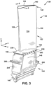
- FIG. 3 shows a perspective view of an illustrative turbine rotor blade 120 of GT system 100 in which integral features according to various embodiments of the disclosure may be employed.
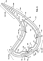
- FIG. 4 shows an axial cross-sectional view of turbine rotor blade 120 including an integral feature in the form of an integral impingement cooling structure 160 according to various embodiments of the disclosure.
- Turbine rotor blade 120 includes an airfoil body 122 including a concave pressure side outer wall 124 and a convex suction side outer wall 126 that connect along leading and trailing edges 128, 130.
- outer walls 124, 126 have an airfoil inner surface 132 defining a radially extending chamber 134 for receiving a coolant flow 136.
- turbine rotor blade 120 may also include a tip end 140 at a radial outer end 142 of airfoil body 122.
- Turbine rotor blade 120 may also include a turbine rotor blade root 144 (hereinafter "root 144") by which turbine rotor blade 120 attaches to rotor 110 ( FIG. 1 ), e.g., by a rotor wheel 147 ( FIG. 21 ).
- root 144 may include any portion of turbine rotor blade 120 including, and radially inward of, platform 150.
- Root 144 may include a blade mount 146 configured for mounting in a corresponding slot in the perimeter of a rotor wheel 147 ( FIG. 21 ).
- Blade mount 146 may have any now known or later developed outer configuration for mounting to rotor disk 147 ( FIG. 21 ) such as but not limited to a dovetail or fir tree arrangement.
- Turbine rotor blade 120 i.e., root 144 thereof, may further include a shank 148 that extends between blade mount 146 and a platform 150.
- Platform 150 is disposed at the junction of airfoil body 122 and shank 148 and defines a portion of the inboard boundary of the flow path through turbine 108 ( FIGS. 1-2 ).
- Shank 148 is thus located at a radial inner end 152 of airfoil body 122, and blade mount 146 is located radially inward of shank 148.
- Platform 150 extends laterally outward relative to shank 148. As will be described further herein, radially extending chamber 134 may extend at least partially into shank 148 to define a shank inner surface 154 ( FIG. 5 ). Outer walls 124 and 126 of airfoil body 122 extend in the radial (Z) direction from platform 150 to tip end 140. It will be appreciated that airfoil body 122 is the active component of turbine rotor blade 120 that intercepts the flow of working fluid and induces the rotor to rotate.
- Turbine rotor blade 120 may also include tip end 140 at radial outer end 142 of airfoil body 122, and shank 148 at radial inner end 152 of airfoil body 122.
- Radially extending chamber 134 may extend at least partially into shank 148 to define shank inner surface 154.
- Integral impingement cooling structure 160 is within radially extending chamber 134, and may include hollow body 162 including a first end 164, a second end 166, an interior surface 168 and an exterior surface 170.
- a plurality of cooling passages 172 extend through hollow body 162 and are in fluid communication with the radially extending chamber 134 to allow the coolant flow to pass from interior surface 168 of hollow body 162 to impinge on the inner surface of at least airfoil body 122.
- first end 164 of hollow body 162 is integrally formed to the shank inner surface 154, i.e., via the additive manufacturing. Consequently, exterior surface 170 of hollow body 162 may be made to be uniformly spaced from airfoil inner surface 132 between first end 164 and second end 166 of the hollow body 162, regardless of the curvature of the airfoil inner surface 132.
- non-uniform, but custom-built, standoff spacing may be employed for purposes of providing different impingement cooling, heat pick-up and/or re-use.
- closer standoff spacing may be employed where increased impingement cooling is required, and wider standoff spacing used where less impingement cooling is required.
- the hollow body 162 may have cooling passages about an entirety of its periphery and radial span to provide impingement cooling throughout the blade, not just at a leading edge thereof.
- the integral impingement cooling structure allows for maximum coverage of impingement with limited sacrifices normally associated with impingement inserts, and can have a number of variable cooling features.
- the turbine rotor blade may have: variable chordwise width for the impingement cooling structure or a pin bank aft thereof, tailored impingement cooling structure wall thickness for different cooling loads, and varied supports to address different coefficients of thermal expansion (CTE) between the airfoil body and impingement cooling structure.
- CTE coefficients of thermal expansion
- turbine rotor blade 120 may include impingement cooling structure 160 within radially extending chamber 134.
- Impingement cooling is typically provided by one or more impingement inserts that are inserted into a radially extending chamber 134 and coupled to airfoil body 122, e.g., by fasteners or welding.
- the impingement inserts are typically linear, but may include some curvature.
- radially extending chamber 134 has a curved airfoil inner surface 132 as in FIG. 5 , it is impossible to have impingement inserts uniformly spaced from the inner surface along an entire radial span of the blade.
- impingement cooling structure 160 according to embodiments of the disclosure is integrally formed with the rest of turbine rotor blade 120, via additive manufacturing.
- impingement cooling structure 160 includes hollow body 162 including first end 164, second end 166, interior surface 168 and exterior surface 170. Impingement cooling structure 160 also includes plurality of cooling passages 172 through hollow body 162 and in fluid communication with radially extending chamber 134 to allow coolant flow 136 to pass from interior surface 168 of the hollow body to impinge on at least airfoil inner surface 132, e.g., it may impinge inner surfaces in, inter alia , airfoil body 122, tip end 140, shank 148, and/or platform 150. In contrast to conventional turbine rotor blades, and as shown in FIG. 4 and especially FIG.
- exterior surface 170 of hollow body 162 is uniformly spaced from airfoil inner surface 132 between first end 164 and second end 166 of hollow body 162. That is, using additive manufacturing rather than mechanical insertion, impingement cooling structure 160 can be formed (simultaneously with, e.g., airfoil inner surface 132) to have the same curvature, bends, twists and any other shape or dimension, to match that of the inner surface adjacent thereto. Notably, impingement cooling structure 160 can be uniformly spaced from airfoil inner surface 132 along an entire radial span that it covers, ensuring the desired Z/D parameter over all of turbine rotor blade 120.
- the Z/D parameter is a ratio of a standoff distance Z between exterior surface 170 and an inner surface (e.g., airfoil inner surface 132, shank inner surface 154, etc.) of turbine rotor blade 120 and a diameter D of cooling passages 172 (holes) in impingement cooling structure 160.
- Z/D ranges from approximately 1 to approximately 10.
- Z/D may range from approximately 2 to approximately 6.
- a standoff distance Z may be smaller than conventionally available for castings, e.g., less than approximately 1.27 millimeters (0.05 inches). Smaller diameter D cooling passages 172 than conventional castings may also be employed, e.g., as a function of clogging from debris.
- cooling passages 172 may extend around an entire peripheral extent of hollow body 162 such that coolant flow 136 exits hollow body 162 in all directions to provide impingement cooling to all of airfoil inner surface 132 of airfoil body 122.
- cooling passages 172 may be omitted in areas where impingement cooling of inner surfaces 132, 154 is not desired or required. Cooling passages 172 may extend along any desired radial extent of hollow body 162.
- first end 164 of hollow body 162 is integrally formed to shank inner surface 154.
- First end 164 meets shank inner surface 154 at a meeting location 174, which extends about the entire periphery of first end 164, i.e., there are no openings between first end 164 and shank inner surface 154 at meeting location (other than perhaps a cooling passage 172).
- first end 164 of hollow body 162 is integrally formed to shank inner surface 154 radially inward of platform 150.
- this particular meeting location 174 may not be necessary in all instances, e.g., in some cases, meeting location 174 may be radially outward of platform 150.
- second end 166 of hollow body 162 may also be integrally formed to inner surface 176 of tip end 140.
- Cooling passages 172 may optionally provide impingement cooling of tip end 140, or pass coolant to tip end 140 for other forms of cooling.
- FIG. 6 shows an enlarged cross-sectional view of meeting location 174 ( FIG. 5 ) of impingement cooling structure 160 and shank 148 of turbine rotor blade 120, according to various embodiments of the disclosure.
- first end 164 of hollow body 162 may extend substantially in a radial direction (arrow Z) relative to meeting location 174 of first end 164 of hollow body 162 and shank inner surface 154.
- substantially in a radial direction indicates that first end 164 extends radially away from rotor 110 ( FIG. 1 ) with some degree of tolerance, e.g., +/-5°.
- shank inner surface 154 extends at an angle ⁇ relative to radial direction Z from meeting location 174 of first end 164 of hollow body 162 and shank 148 ( FIG. 6 ).
- shank inner surface 154 is aligned substantially in a radial direction and first end 164 of hollow body gradually curves or transitions towards meeting location 174 to keep angle ⁇ , for example, ⁇ 30°.
- both shank inner surface 154 and first end 164 of hollow body 162 gradually curve or transition towards meeting location 174.
- Angle ⁇ may be any angle desired and within the range of additive manufacture, e.g., ⁇ 45° from vertical.
- hollow body 162 may include at least one first portion 182 having a first wall thickness W1 between interior surface 168 and exterior surface 170 thereof, and at least one second portion 184 having a second wall thickness W2 between interior surface 168 and exterior surface 170 thereof.
- first wall thickness W1 is greater than second wall thickness W2.
- Any number of thicker and/or thinner portions 182, 184 may be provided in impingement cooling structure 160.
- the thickness of portions 182, 184 may be any dimension desired to address the structural and/or thermal requirements of the location.
- source of the coolant 236 to cooling circuit 234 may provide the coolant directly from radially extending chamber 134.
- Other sources of coolant 236 may also be used, e.g., wheel space portion between shanks 148 of adjacent turbine rotor blades 120.
- Cooling circuit 234 may take any now known or later developed form. In the example shown in FIG. 13 , cooling circuit 234 includes a sinusoidal path through platform 150. In contrast, in FIG. 12 , cooling circuit 234 includes an elbow path. Cooling circuit 234 may have a less complex path or a more complex path, and may extend where necessary to cool platform 150.
- cooling passage(s) 240 may have a non-linear configuration that extends from cooling circuit 234 radially outward and about damper pin seat 246 to outer surface 242 of slash face 230, i.e., in a curved shape that is sharper or more turning than FIG. 12 .
- Turbine rotor blade 120 may also include shank 148 at radial inner end 152 of airfoil body 122.
- turbine rotor blade 120 includes at least one angel wing 280 extending laterally from at least one side 282, 284 of shank 148.
- turbine rotor blade 120 typically includes axially projecting angel wing seals 280, also simply referred to as 'angel wings'.
- Angel wings 280 cooperate with projecting segments or 'discouragers' 288 which extend from nozzle 112. Angel wings 280 and discouragers 288 overlap (or nearly overlap), but do not touch each other, thus restricting fluid flow.
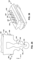
- turbine rotor blade 120 may also include a coolant transfer passage 290 defined through the at least one angel wing 280.
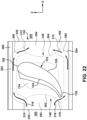
- Coolant transfer passage 290 e.g., for a first turbine rotor blade 120A ( FIG. 21 ), fluidly couples a first wheel space portion 292 defined between shank 148A ( FIG. 21 ) and a first adjacent shank 148B ( FIG. 21 ) of a first adjacent turbine rotor blade 120B and a second wheel space portion 294 defined between shank 148A ( FIG. 21 ) and a second adjacent shank 148C of a second adjacent turbine rotor blade 120C ( FIG. 21 ).
- FIGS. 21 As shown best by observing FIGS.
- each wheel space portion 292, 294 is part of wheel space 300.
- Wheel space 300 is defined: circumferentially between shanks 148A-C ( FIG. 21 ) of adjacent turbine rotor blades 120A-C, axially between shank 148 and an adjacent nozzle 112, and radially by platform 150 and rotor disks 147.
- Wheel space portions 292, 294 are that part of wheel space 300 that is axially beside a particular blade's shank 148.
- coolant transfer passage 290 includes a first open end 310 in fluid communication with first wheel space portion 292 and a second open end 312 in fluid communication with second wheel space portion 294.
- coolant transfer passage 290 allows a wheel space coolant 316 to pass between wheel space portions 292, 294 on circumferentially opposing sides of shank 148.
- First open end 310 and second open end 312 may face in an axial-circumferential direction relative to airfoil body 122, or any direction that will allow wheel space coolant 316 to pass between wheel space portions 292, 294.
- Wheel space coolant 316 may be any now known or later developed coolant, e.g., routed from compressor 102 ( FIG. 1 ).
- outer walls 124, 126 of airfoil body 122 define radially extending chamber 134 that may extend into shank 148.
- coolant transfer passage 290 is fluidly isolated from radially extending chamber 134, i.e., coolant flow 136 ( FIG. 4 ) from chamber 134 does not mix with wheel space coolant 316.
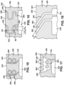
- Turbine rotor blade root 144 may further include a lattice support structure 340 disposed within hollow interior 330 of the blade mount 146.
- Lattice support structure 340 may take a variety of hollow support structure forms.
- lattice support structure 340 may include a plurality of radially extending V-shaped sections 342.
- V-shaped sections 342 may be integral with inner wall surfaces 344 of blade mount 146.
- Root 144 including shank 148 and blade mount 146, including lattice support structure 340, may be made by additive manufacture. Shank 148 and blade mount 146 thus may include a plurality of integral material layers.
- Root 144 may also include angel wing(s) 280 extending laterally from at least one side of shank 148, as described herein relative to FIGS. 19-24 .
- a coolant transfer passage 290 may be defined through angel wing(s) 280.
- coolant transfer passage 290 fluidly couples a first wheel space portion 292 defined between shank 148A and a first adjacent shank 148B of a first adjacent turbine rotor blade root 144B and a second wheel space portion 294 defined between shank 148A and a second adjacent shank 148C of a second adjacent turbine rotor blade root 144C.
- Root 144 may also include both platform 150 and angel wing(s) 280, as described herein. Additive manufacture allows for formation of root 144 with shank 148, hollow blade mount 146, lattice support structure 340, and platform 150 and/or angel wing(s) 280, creating a plurality of integral material layers for whatever features are provided.
Landscapes
- Engineering & Computer Science (AREA)
- Mechanical Engineering (AREA)
- General Engineering & Computer Science (AREA)
- Architecture (AREA)
- Chemical & Material Sciences (AREA)
- Manufacturing & Machinery (AREA)
- Materials Engineering (AREA)
- Turbine Rotor Nozzle Sealing (AREA)
Applications Claiming Priority (2)
| Application Number | Priority Date | Filing Date | Title |
|---|---|---|---|
| US16/749,167 US11248471B2 (en) | 2020-01-22 | 2020-01-22 | Turbine rotor blade with angel wing with coolant transfer passage between adjacent wheel space portions by additive manufacture |
| PCT/US2021/013387 WO2021150418A1 (en) | 2020-01-22 | 2021-01-14 | Turbine rotor blade with angel wing seals with coolant transfer passage between adjacent wheel space portions by additive manufacture |
Publications (2)
| Publication Number | Publication Date |
|---|---|
| EP4093944A1 EP4093944A1 (en) | 2022-11-30 |
| EP4093944B1 true EP4093944B1 (en) | 2025-07-09 |
Family
ID=74562067
Family Applications (1)
| Application Number | Title | Priority Date | Filing Date |
|---|---|---|---|
| EP21704126.8A Active EP4093944B1 (en) | 2020-01-22 | 2021-01-14 | Turbine rotor blade with angel wing seals with coolant transfer passage between adjacent wheel space portions by additive manufacture |
Country Status (6)
| Country | Link |
|---|---|
| US (1) | US11248471B2 (https=) |
| EP (1) | EP4093944B1 (https=) |
| JP (1) | JP7646670B2 (https=) |
| KR (1) | KR102889298B1 (https=) |
| CN (1) | CN114867930B (https=) |
| WO (1) | WO2021150418A1 (https=) |
Families Citing this family (9)
| Publication number | Priority date | Publication date | Assignee | Title |
|---|---|---|---|---|
| US11248471B2 (en) | 2020-01-22 | 2022-02-15 | General Electric Company | Turbine rotor blade with angel wing with coolant transfer passage between adjacent wheel space portions by additive manufacture |
| US11492908B2 (en) | 2020-01-22 | 2022-11-08 | General Electric Company | Turbine rotor blade root with hollow mount with lattice support structure by additive manufacture |
| US11242760B2 (en) * | 2020-01-22 | 2022-02-08 | General Electric Company | Turbine rotor blade with integral impingement sleeve by additive manufacture |
| US11552523B2 (en) * | 2020-05-28 | 2023-01-10 | Honeywell International Inc. | Conformal cooling devices for rotating generator elements and additive manufacturing processes for fabricating the same |
| KR102621756B1 (ko) * | 2020-11-27 | 2024-01-09 | 연세대학교 산학협력단 | 격자구조의 냉각방식을 갖는 가스터빈 베인 및 블레이드 |
| US20250188843A1 (en) * | 2022-08-24 | 2025-06-12 | General Electric Company | Turbine engine airfoil |
| US12571351B2 (en) | 2023-06-14 | 2026-03-10 | General Electric Company | Gas turbine engine defining a rotor cavity |
| US20250369359A1 (en) * | 2024-05-29 | 2025-12-04 | Rtx Corporation | Cooling features for a component of a gas turbine engine |
| US12497897B1 (en) * | 2024-09-03 | 2025-12-16 | Ge Infrastructure Technology Llc | Airfoil component for turbomachine component with platform cooling using airfoil coolant |
Citations (1)
| Publication number | Priority date | Publication date | Assignee | Title |
|---|---|---|---|---|
| EP0801208B1 (en) * | 1996-04-12 | 2002-12-04 | United Technologies Corporation | Cooled rotor assembly for a turbine engine |
Family Cites Families (38)
| Publication number | Priority date | Publication date | Assignee | Title |
|---|---|---|---|---|
| US3628885A (en) * | 1969-10-01 | 1971-12-21 | Gen Electric | Fluid-cooled airfoil |
| US3867068A (en) | 1973-03-30 | 1975-02-18 | Gen Electric | Turbomachinery blade cooling insert retainers |
| US4203706A (en) | 1977-12-28 | 1980-05-20 | United Technologies Corporation | Radial wafer airfoil construction |
| US5816777A (en) | 1991-11-29 | 1998-10-06 | United Technologies Corporation | Turbine blade cooling |
| JPH0953406A (ja) | 1995-08-14 | 1997-02-25 | Mitsubishi Heavy Ind Ltd | インピンジメント冷却装置及びガスタービン翼 |
| DE19634237A1 (de) | 1996-08-23 | 1998-02-26 | Asea Brown Boveri | Kühlbare Schaufel |
| EP0905353B1 (de) | 1997-09-30 | 2003-01-15 | ALSTOM (Switzerland) Ltd | Prallanordnung für ein konvektives Kühl- oder Heizverfahren |
| US6435813B1 (en) | 2000-05-10 | 2002-08-20 | General Electric Company | Impigement cooled airfoil |
| US6402471B1 (en) * | 2000-11-03 | 2002-06-11 | General Electric Company | Turbine blade for gas turbine engine and method of cooling same |
| GB0515868D0 (en) | 2005-08-02 | 2005-09-07 | Rolls Royce Plc | Cooling arrangement |
| US7563072B1 (en) | 2006-09-25 | 2009-07-21 | Florida Turbine Technologies, Inc. | Turbine airfoil with near-wall spiral flow cooling circuit |
| US7837441B2 (en) | 2007-02-16 | 2010-11-23 | United Technologies Corporation | Impingement skin core cooling for gas turbine engine blade |
| US7785071B1 (en) | 2007-05-31 | 2010-08-31 | Florida Turbine Technologies, Inc. | Turbine airfoil with spiral trailing edge cooling passages |
| US8057183B1 (en) | 2008-12-16 | 2011-11-15 | Florida Turbine Technologies, Inc. | Light weight and highly cooled turbine blade |
| ES2389034T3 (es) | 2009-05-19 | 2012-10-22 | Alstom Technology Ltd | Pala de turbina a gas con refrigeración mejorada |
| US8523527B2 (en) * | 2010-03-10 | 2013-09-03 | General Electric Company | Apparatus for cooling a platform of a turbine component |
| US8366394B1 (en) * | 2010-10-21 | 2013-02-05 | Florida Turbine Technologies, Inc. | Turbine blade with tip rail cooling channel |
| US20130104567A1 (en) | 2011-10-31 | 2013-05-02 | Douglas Gerard Konitzer | Method and apparatus for cooling gas turbine rotor blades |
| US8905714B2 (en) | 2011-12-30 | 2014-12-09 | General Electric Company | Turbine rotor blade platform cooling |
| US9249673B2 (en) | 2011-12-30 | 2016-02-02 | General Electric Company | Turbine rotor blade platform cooling |
| US20130170983A1 (en) * | 2012-01-04 | 2013-07-04 | General Electric Company | Turbine assembly and method for reducing fluid flow between turbine components |
| US9810070B2 (en) | 2013-05-15 | 2017-11-07 | General Electric Company | Turbine rotor blade for a turbine section of a gas turbine |
| US10533453B2 (en) | 2013-08-05 | 2020-01-14 | United Technologies Corporation | Engine component having platform with passageway |
| US9528377B2 (en) | 2013-08-21 | 2016-12-27 | General Electric Company | Method and system for cooling rotor blade angelwings |
| EP3047105B1 (en) * | 2013-09-17 | 2021-06-09 | Raytheon Technologies Corporation | Platform cooling core for a gas turbine engine rotor blade |
| US20150184538A1 (en) * | 2013-12-30 | 2015-07-02 | General Electric Company | Interior cooling circuits in turbine blades |
| FR3034129B1 (fr) | 2015-03-27 | 2019-05-17 | Safran Aircraft Engines | Aube mobile de turbine a conception amelioree pour turbomachine d'aeronef |
| EP3232000A1 (de) | 2016-04-15 | 2017-10-18 | Siemens Aktiengesellschaft | Plattform einer laufschaufel mit filmkühlungsöffnungen an der plattform und zugehörige strömugsmaschine |
| US10450868B2 (en) * | 2016-07-22 | 2019-10-22 | General Electric Company | Turbine rotor blade with coupon having corrugated surface(s) |
| US10436037B2 (en) | 2016-07-22 | 2019-10-08 | General Electric Company | Blade with parallel corrugated surfaces on inner and outer surfaces |
| JP6860383B2 (ja) * | 2017-03-10 | 2021-04-14 | 川崎重工業株式会社 | タービン翼の冷却構造 |
| US10941671B2 (en) * | 2017-03-23 | 2021-03-09 | General Electric Company | Gas turbine engine component incorporating a seal slot |
| US11085306B2 (en) * | 2017-03-29 | 2021-08-10 | Siemens Energy Global GmbH & Co. KG | Turbine rotor blade with airfoil cooling integrated with impingement platform cooling |
| US10323520B2 (en) | 2017-06-13 | 2019-06-18 | General Electric Company | Platform cooling arrangement in a turbine rotor blade |
| EP3447245A1 (en) | 2017-08-22 | 2019-02-27 | Siemens Aktiengesellschaft | Turbine blade foot |
| US20190264569A1 (en) * | 2018-02-23 | 2019-08-29 | General Electric Company | Turbine rotor blade with exiting hole to deliver fluid to boundary layer film |
| US11248471B2 (en) | 2020-01-22 | 2022-02-15 | General Electric Company | Turbine rotor blade with angel wing with coolant transfer passage between adjacent wheel space portions by additive manufacture |
| US11220916B2 (en) | 2020-01-22 | 2022-01-11 | General Electric Company | Turbine rotor blade with platform with non-linear cooling passages by additive manufacture |
-
2020
- 2020-01-22 US US16/749,167 patent/US11248471B2/en active Active
-
2021
- 2021-01-14 KR KR1020227024486A patent/KR102889298B1/ko active Active
- 2021-01-14 EP EP21704126.8A patent/EP4093944B1/en active Active
- 2021-01-14 WO PCT/US2021/013387 patent/WO2021150418A1/en not_active Ceased
- 2021-01-14 CN CN202180007604.7A patent/CN114867930B/zh active Active
- 2021-01-14 JP JP2022538315A patent/JP7646670B2/ja active Active
Patent Citations (1)
| Publication number | Priority date | Publication date | Assignee | Title |
|---|---|---|---|---|
| EP0801208B1 (en) * | 1996-04-12 | 2002-12-04 | United Technologies Corporation | Cooled rotor assembly for a turbine engine |
Also Published As
| Publication number | Publication date |
|---|---|
| KR102889298B1 (ko) | 2025-11-25 |
| JP2023513663A (ja) | 2023-04-03 |
| EP4093944A1 (en) | 2022-11-30 |
| KR20220125257A (ko) | 2022-09-14 |
| US11248471B2 (en) | 2022-02-15 |
| US20210222566A1 (en) | 2021-07-22 |
| CN114867930B (zh) | 2026-01-06 |
| CN114867930A (zh) | 2022-08-05 |
| WO2021150418A1 (en) | 2021-07-29 |
| JP7646670B2 (ja) | 2025-03-17 |
Similar Documents
| Publication | Publication Date | Title |
|---|---|---|
| EP4234131B1 (en) | Turbine rotor blade | |
| EP4093944B1 (en) | Turbine rotor blade with angel wing seals with coolant transfer passage between adjacent wheel space portions by additive manufacture | |
| EP3854991B1 (en) | Turbine rotor blade | |
| EP3287594B1 (en) | Coupon for hot gas path component having manufacturing assisting features | |
| US20180010457A1 (en) | Coupon for hot gas path component having manufacturing assist features | |
| US10934852B2 (en) | Turbine blade tip cooling system including tip rail cooling insert | |
| US20250135751A1 (en) | Metal Coupon With Porous Regions and Slanted Side Wall(s) for Turbomachine Component | |
| US20250135545A1 (en) | Metal porous coupon with anchor for component and component with same | |
| EP3854993B1 (en) | Turbine rotor blade root |
Legal Events
| Date | Code | Title | Description |
|---|---|---|---|
| STAA | Information on the status of an ep patent application or granted ep patent |
Free format text: STATUS: UNKNOWN |
|
| STAA | Information on the status of an ep patent application or granted ep patent |
Free format text: STATUS: THE INTERNATIONAL PUBLICATION HAS BEEN MADE |
|
| PUAI | Public reference made under article 153(3) epc to a published international application that has entered the european phase |
Free format text: ORIGINAL CODE: 0009012 |
|
| STAA | Information on the status of an ep patent application or granted ep patent |
Free format text: STATUS: REQUEST FOR EXAMINATION WAS MADE |
|
| 17P | Request for examination filed |
Effective date: 20220704 |
|
| AK | Designated contracting states |
Kind code of ref document: A1 Designated state(s): AL AT BE BG CH CY CZ DE DK EE ES FI FR GB GR HR HU IE IS IT LI LT LU LV MC MK MT NL NO PL PT RO RS SE SI SK SM TR |
|
| DAV | Request for validation of the european patent (deleted) | ||
| DAX | Request for extension of the european patent (deleted) | ||
| RAP1 | Party data changed (applicant data changed or rights of an application transferred) |
Owner name: GENERAL ELECTRIC TECHNOLOGY GMBH |
|
| STAA | Information on the status of an ep patent application or granted ep patent |
Free format text: STATUS: EXAMINATION IS IN PROGRESS |
|
| 17Q | First examination report despatched |
Effective date: 20240628 |
|
| GRAP | Despatch of communication of intention to grant a patent |
Free format text: ORIGINAL CODE: EPIDOSNIGR1 |
|
| STAA | Information on the status of an ep patent application or granted ep patent |
Free format text: STATUS: GRANT OF PATENT IS INTENDED |
|
| INTG | Intention to grant announced |
Effective date: 20250115 |
|
| GRAS | Grant fee paid |
Free format text: ORIGINAL CODE: EPIDOSNIGR3 |
|
| GRAA | (expected) grant |
Free format text: ORIGINAL CODE: 0009210 |
|
| STAA | Information on the status of an ep patent application or granted ep patent |
Free format text: STATUS: THE PATENT HAS BEEN GRANTED |
|
| AK | Designated contracting states |
Kind code of ref document: B1 Designated state(s): AL AT BE BG CH CY CZ DE DK EE ES FI FR GB GR HR HU IE IS IT LI LT LU LV MC MK MT NL NO PL PT RO RS SE SI SK SM TR |
|
| REG | Reference to a national code |
Ref country code: GB Ref legal event code: FG4D |
|
| REG | Reference to a national code |
Ref country code: CH Ref legal event code: EP |
|
| REG | Reference to a national code |
Ref country code: IE Ref legal event code: FG4D |
|
| REG | Reference to a national code |
Ref country code: DE Ref legal event code: R096 Ref document number: 602021033733 Country of ref document: DE |
|
| RAP4 | Party data changed (patent owner data changed or rights of a patent transferred) |
Owner name: GE VERNOVA TECHNOLOGY GMBH |
|
| REG | Reference to a national code |
Ref country code: NL Ref legal event code: MP Effective date: 20250709 |
|
| PG25 | Lapsed in a contracting state [announced via postgrant information from national office to epo] |
Ref country code: PT Free format text: LAPSE BECAUSE OF FAILURE TO SUBMIT A TRANSLATION OF THE DESCRIPTION OR TO PAY THE FEE WITHIN THE PRESCRIBED TIME-LIMIT Effective date: 20251110 |
|
| PG25 | Lapsed in a contracting state [announced via postgrant information from national office to epo] |
Ref country code: NL Free format text: LAPSE BECAUSE OF FAILURE TO SUBMIT A TRANSLATION OF THE DESCRIPTION OR TO PAY THE FEE WITHIN THE PRESCRIBED TIME-LIMIT Effective date: 20250709 |
|
| REG | Reference to a national code |
Ref country code: AT Ref legal event code: MK05 Ref document number: 1811999 Country of ref document: AT Kind code of ref document: T Effective date: 20250709 |
|
| PG25 | Lapsed in a contracting state [announced via postgrant information from national office to epo] |
Ref country code: IS Free format text: LAPSE BECAUSE OF FAILURE TO SUBMIT A TRANSLATION OF THE DESCRIPTION OR TO PAY THE FEE WITHIN THE PRESCRIBED TIME-LIMIT Effective date: 20251109 |
|
| PG25 | Lapsed in a contracting state [announced via postgrant information from national office to epo] |
Ref country code: NO Free format text: LAPSE BECAUSE OF FAILURE TO SUBMIT A TRANSLATION OF THE DESCRIPTION OR TO PAY THE FEE WITHIN THE PRESCRIBED TIME-LIMIT Effective date: 20251009 |
|
| REG | Reference to a national code |
Ref country code: LT Ref legal event code: MG9D |
|
| PG25 | Lapsed in a contracting state [announced via postgrant information from national office to epo] |
Ref country code: AT Free format text: LAPSE BECAUSE OF FAILURE TO SUBMIT A TRANSLATION OF THE DESCRIPTION OR TO PAY THE FEE WITHIN THE PRESCRIBED TIME-LIMIT Effective date: 20250709 |
|
| PG25 | Lapsed in a contracting state [announced via postgrant information from national office to epo] |
Ref country code: FI Free format text: LAPSE BECAUSE OF FAILURE TO SUBMIT A TRANSLATION OF THE DESCRIPTION OR TO PAY THE FEE WITHIN THE PRESCRIBED TIME-LIMIT Effective date: 20250709 |
|
| PG25 | Lapsed in a contracting state [announced via postgrant information from national office to epo] |
Ref country code: HR Free format text: LAPSE BECAUSE OF FAILURE TO SUBMIT A TRANSLATION OF THE DESCRIPTION OR TO PAY THE FEE WITHIN THE PRESCRIBED TIME-LIMIT Effective date: 20250709 |
|
| PG25 | Lapsed in a contracting state [announced via postgrant information from national office to epo] |
Ref country code: GR Free format text: LAPSE BECAUSE OF FAILURE TO SUBMIT A TRANSLATION OF THE DESCRIPTION OR TO PAY THE FEE WITHIN THE PRESCRIBED TIME-LIMIT Effective date: 20251010 |
|
| PG25 | Lapsed in a contracting state [announced via postgrant information from national office to epo] |
Ref country code: SE Free format text: LAPSE BECAUSE OF FAILURE TO SUBMIT A TRANSLATION OF THE DESCRIPTION OR TO PAY THE FEE WITHIN THE PRESCRIBED TIME-LIMIT Effective date: 20250709 |
|
| PG25 | Lapsed in a contracting state [announced via postgrant information from national office to epo] |
Ref country code: LV Free format text: LAPSE BECAUSE OF FAILURE TO SUBMIT A TRANSLATION OF THE DESCRIPTION OR TO PAY THE FEE WITHIN THE PRESCRIBED TIME-LIMIT Effective date: 20250709 |
|
| PG25 | Lapsed in a contracting state [announced via postgrant information from national office to epo] |
Ref country code: BG Free format text: LAPSE BECAUSE OF FAILURE TO SUBMIT A TRANSLATION OF THE DESCRIPTION OR TO PAY THE FEE WITHIN THE PRESCRIBED TIME-LIMIT Effective date: 20250709 Ref country code: PL Free format text: LAPSE BECAUSE OF FAILURE TO SUBMIT A TRANSLATION OF THE DESCRIPTION OR TO PAY THE FEE WITHIN THE PRESCRIBED TIME-LIMIT Effective date: 20250709 |
|
| PG25 | Lapsed in a contracting state [announced via postgrant information from national office to epo] |
Ref country code: RS Free format text: LAPSE BECAUSE OF FAILURE TO SUBMIT A TRANSLATION OF THE DESCRIPTION OR TO PAY THE FEE WITHIN THE PRESCRIBED TIME-LIMIT Effective date: 20251009 |
|
| PG25 | Lapsed in a contracting state [announced via postgrant information from national office to epo] |
Ref country code: ES Free format text: LAPSE BECAUSE OF FAILURE TO SUBMIT A TRANSLATION OF THE DESCRIPTION OR TO PAY THE FEE WITHIN THE PRESCRIBED TIME-LIMIT Effective date: 20250709 |
|
| PG25 | Lapsed in a contracting state [announced via postgrant information from national office to epo] |
Ref country code: SM Free format text: LAPSE BECAUSE OF FAILURE TO SUBMIT A TRANSLATION OF THE DESCRIPTION OR TO PAY THE FEE WITHIN THE PRESCRIBED TIME-LIMIT Effective date: 20250709 |
|
| PG25 | Lapsed in a contracting state [announced via postgrant information from national office to epo] |
Ref country code: DK Free format text: LAPSE BECAUSE OF FAILURE TO SUBMIT A TRANSLATION OF THE DESCRIPTION OR TO PAY THE FEE WITHIN THE PRESCRIBED TIME-LIMIT Effective date: 20250709 |
|
| PGFP | Annual fee paid to national office [announced via postgrant information from national office to epo] |
Ref country code: DE Payment date: 20251217 Year of fee payment: 6 |
|
| PG25 | Lapsed in a contracting state [announced via postgrant information from national office to epo] |
Ref country code: IT Free format text: LAPSE BECAUSE OF FAILURE TO SUBMIT A TRANSLATION OF THE DESCRIPTION OR TO PAY THE FEE WITHIN THE PRESCRIBED TIME-LIMIT Effective date: 20250709 |
|
| PG25 | Lapsed in a contracting state [announced via postgrant information from national office to epo] |
Ref country code: CZ Free format text: LAPSE BECAUSE OF FAILURE TO SUBMIT A TRANSLATION OF THE DESCRIPTION OR TO PAY THE FEE WITHIN THE PRESCRIBED TIME-LIMIT Effective date: 20250709 |
|
| PG25 | Lapsed in a contracting state [announced via postgrant information from national office to epo] |
Ref country code: EE Free format text: LAPSE BECAUSE OF FAILURE TO SUBMIT A TRANSLATION OF THE DESCRIPTION OR TO PAY THE FEE WITHIN THE PRESCRIBED TIME-LIMIT Effective date: 20250709 Ref country code: SK Free format text: LAPSE BECAUSE OF FAILURE TO SUBMIT A TRANSLATION OF THE DESCRIPTION OR TO PAY THE FEE WITHIN THE PRESCRIBED TIME-LIMIT Effective date: 20250709 |