EP4093174A1 - Component supply unit storage and retrieval system - Google Patents
Component supply unit storage and retrieval system Download PDFInfo
- Publication number
- EP4093174A1 EP4093174A1 EP20914125.8A EP20914125A EP4093174A1 EP 4093174 A1 EP4093174 A1 EP 4093174A1 EP 20914125 A EP20914125 A EP 20914125A EP 4093174 A1 EP4093174 A1 EP 4093174A1
- Authority
- EP
- European Patent Office
- Prior art keywords
- storage
- component supply
- unit
- component
- retrieval
- Prior art date
- Legal status (The legal status is an assumption and is not a legal conclusion. Google has not performed a legal analysis and makes no representation as to the accuracy of the status listed.)
- Granted
Links
Images


Classifications
-
- B—PERFORMING OPERATIONS; TRANSPORTING
- B65—CONVEYING; PACKING; STORING; HANDLING THIN OR FILAMENTARY MATERIAL
- B65G—TRANSPORT OR STORAGE DEVICES, e.g. CONVEYORS FOR LOADING OR TIPPING, SHOP CONVEYOR SYSTEMS OR PNEUMATIC TUBE CONVEYORS
- B65G1/00—Storing articles, individually or in orderly arrangement, in warehouses or magazines
- B65G1/02—Storage devices
- B65G1/04—Storage devices mechanical
- B65G1/137—Storage devices mechanical with arrangements or automatic control means for selecting which articles are to be removed
- B65G1/1373—Storage devices mechanical with arrangements or automatic control means for selecting which articles are to be removed for fulfilling orders in warehouses
- B65G1/1376—Storage devices mechanical with arrangements or automatic control means for selecting which articles are to be removed for fulfilling orders in warehouses the orders being assembled on a commissioning conveyor
-
- H—ELECTRICITY
- H05—ELECTRIC TECHNIQUES NOT OTHERWISE PROVIDED FOR
- H05K—PRINTED CIRCUITS; CASINGS OR CONSTRUCTIONAL DETAILS OF ELECTRIC APPARATUS; MANUFACTURE OF ASSEMBLAGES OF ELECTRICAL COMPONENTS
- H05K13/00—Apparatus or processes specially adapted for manufacturing or adjusting assemblages of electric components
- H05K13/08—Monitoring manufacture of assemblages
- H05K13/086—Supply management, e.g. supply of components or of substrates
-
- H—ELECTRICITY
- H05—ELECTRIC TECHNIQUES NOT OTHERWISE PROVIDED FOR
- H05K—PRINTED CIRCUITS; CASINGS OR CONSTRUCTIONAL DETAILS OF ELECTRIC APPARATUS; MANUFACTURE OF ASSEMBLAGES OF ELECTRICAL COMPONENTS
- H05K13/00—Apparatus or processes specially adapted for manufacturing or adjusting assemblages of electric components
- H05K13/02—Feeding of components
Definitions
- the present specification relates to a storage and retrieval system corresponding to a set-up work involving retrieval of a component supply unit from a warehouse.
- a technique of mass-producing board products by performing board work on a board on which printed wiring is performed has become widespread. Further, it is common to provide multiple types of board work machines for performing the board work side by side so as to configure a board work line.
- a component mounter among the board work machines uses a component supply unit loaded with the component container that contains multiple components.
- the loading operation for loading the component supply unit with the component container in other words, a set-up operation for preparing the component supply unit for use, is often performed in a set-up area distant from the component mounter being operated (external set-up).
- the set-up component supply unit is conveyed to and installed in a component mounter (internal set-up).
- Patent Literature 1 describes a configuration including a storage shed for storing a reel (one example of the component container), a storage shed for storing a feeder (one example of the component supply unit), a reel set device, a conveyance device, and a management section.
- the reel set device performs the set-up work for setting a reel to a feeder.
- the conveyance device conveys the set-up feeder to the component mounter.
- the management section controls the retrieval, the set-up work, the conveyance operation, or the like of the reels and the feeders, and manages the production of the component mounter. According to this configuration, it is said that the combination and the location of the reel and the feeder can be easily recognized so that the real and the feeder can be easily managed.
- Patent Literature 1 International Publication No. 2019/142336
- the loading operation is automated. However, since the loading operation is performed one by one in order, which is not necessarily efficient.
- the present specification discloses a component supply unit storage and retrieval system including a unit storage configured to store multiple component supply units used when multiple components are supplied to a component mounter, a storage holding base configured to hold the unit storage, a unit warehouse configured to store the component supply units more than the unit storage, and a storage and retrieval robot configured to deliver the component supply unit between the unit storage and the unit warehouse.
- a storage and retrieval robot automatically performs an operation of retrieving multiple component supply units from a unit warehouse and storing the same in a unit storage.
- the multiple component supply units stored in the unit storage are collectively utilized in a subsequent set-up work or are collectively installed in a component mounter. Therefore, it is possible to improve the efficiency of the set-up work as compared with the conventional technique in which the component supply units are set-up one by one.
- Storage and retrieval system 1 corresponds to a loading operation for loading component supply unit 92 with component container 91 and related operations before and after the loading operation.
- Storage and retrieval system 1 is configured to include unit warehouse 2, storage holding base 3, unit storages (41, 44), and storage and retrieval robot 5.
- Component container 91 is loaded in component supply unit 92 while containing multiple components.
- Component supply unit 92 is used when supplying the components contained in component container 91 in a mounting operation performed by component mounter 98.
- Identification codes indicating each type or individual are attached to component container 91 and component supply unit 92.
- the identification code of component container 91 includes information indicating the type of the component contained in component container 91.
- As the identification code a barcode, a two-dimensional code, or the like is used.
- load information V (see Fig. 3 ) associating an individual of component container 91 with an individual of component supply unit 92, which is loaded with component container 91, is created.
- a tape reel can be exemplified, and as component supply unit 92, an integral type feeder device in which the tape reel is directly loaded can be exemplified.
- a carrier tape in which multiple components are sealed at a predetermined pitch is wound and held on the tape reel.
- the feeder device is installed on component mounter 98 in a form to which the tape reel is loaded.
- the feeder device supplies the component to a component mounting tool of component mounter 98 by pulling out the carrier tape from the tape reel and sending the carrier tape to a component pick up position.
- the feeder device is not limited to an integral type and may be a separate type.
- the separate type feeder device is configured to include a feeder main body portion having a feeding mechanism of the carrier tape and a reel cassette to which the tape reel is loaded.
- the feeder main body portion is permanently provided in component mounter 98, and the separate reel cassette is disposed in the vicinity of the feeder main body portion.
- the reel cassette is exchanged.
- the reel cassette corresponds to component supply unit 92 to which component container 91 is loaded.
- component supply unit 92 is an integral type feeder device and a tape reel serving as component container 91 is already loaded will be described.
- a tray may be used as component container 91, and a tray loading unit may be used as component supply unit 92.
- Unit warehouse 2 stores component supply units 92 more than component supply units 92 stored in unit storages 41 and 44 described later. As illustrated in Figs. 1 and 2 , unit warehouse 2 is formed in a large vertical rectangular parallelepiped shape. Unit warehouse 2 includes a storage and retrieval port 21 on a front face thereof. However, the configuration is not limited to this, a storage port and a retrieval port may be provided separately. Component supply unit 92, which is loaded with component container 91, is stored from storage and retrieval port 21 by an operator.
- Upper section guide 26 extending in the left-right direction is provided on a lower portion of storage and retrieval port 21 on the front face of unit warehouse 2.
- Lower section guide 27 extending in the left-right direction is provided on a lowermost portion of the front face of unit warehouse 2.
- Upper section guide 26 and lower section guide 27 are formed in, for example, a protrusion shape protruding ahead or a groove shape opened upward.
- actuator 22 transfers component container 91 stored in storage and retrieval port 21 to a storing position, or transfers the component container 91 in the storing position to storage and retrieval port 21.
- Actuator 22 is controlled by warehouse control section 29.
- Code reader 23 reads the identification code attached to stored component supply unit 92 and delivers the read result to warehouse control section 29. Therefore, warehouse control section 29 can recognize the individuals of all stored component supply units 92 in association with the storing positions. Further, warehouse control section 29 can recognize component container 91 loaded in each of the component supply units 92 with reference to load information V.
- Warning lamp 24 is provided on the right front side of the upper portion of unit warehouse 2. Warehouse control section 29 controls the lighting of warning lamp 24 when an abnormality occurs or a failure occurs and notifies an operator of the same.
- storage holding base 3 is disposed on the left side of unit warehouse 2 adjacent to each other.
- storage holding base 3 may be disposed on the right side of unit warehouse 2.
- Storage holding base 3 holds unit storages 41 and 44 on the upper side.
- Storage holding base 3 is formed in a rectangular parallelepiped frame shape.
- Upper section guide 32 extending in the left-right direction is provided on an upper portion of the front face of storage holding base 3.
- Lower section guide 33 extending in the left-right direction is provided on a lower portion of the front face of storage holding base 3.
- Upper section guide 32 and Lower section guide 33 are disposed at the same height as upper section guide 26 and lower section guide 27 of unit warehouse 2, and are formed in the same shape.
- Storage holding base 3 is capable of being additionally installed. When storage holding base 3 is additionally installed, multiple storage holding bases 3 are disposed adjacent to each other in the left-right direction. Further, multiple storage holding bases 3 may be disposed so as to be dispersed on both the left and right sides of unit warehouse 2. As a result, multiple upper section guides 32 are connected in the left-right direction and are further connected to upper section guide 26 of unit warehouse 2 to form a long movement guide. Similarly, multiple lower section guides 33 are connected in the left-right direction and are further connected to lower section guide 27 of unit warehouse 2 to form a long movement guide.
- Full width unit storages 41 are held on the right side and center on the upper side of storage holding bases 3 among three storage holding bases 3 illustrated in Figs. 1 and 2 . Further, two half width unit storages 44 are held on the upper side of storage holding base 3 on the left side.
- the width dimension of full width unit storage 41 is slightly smaller than the width dimension of component mounter 98.
- the width dimension of half width unit storage 44 is substantially half the width dimension of full width unit storage 41.
- Unit storages (41, 44) stores multiple component supply units 92.
- Multiple storage slots set-up in the left-right direction are formed on the bottom face of the inner side of unit storages (41, 44).
- Storage slot is formed with, for example, a groove extending in the front-rear direction, into which component supply unit 92 is inserted from the front side and stored.
- one component supply unit 92 is illustrated in full width unit storage 41 on the right side, and in actuality, multiple component supply units 92 are stored side by side in the left-right direction.
- the number of storage slots of half width unit storage 44 is half of the number of storage slots of full width unit storage 41.
- Full width unit storage 41 is installed on component mounter 98 and serves as a main portion of a component supply device.
- two half width unit storages 44 are installed on component mounter 98 to serve as a main portion of the component supply device.
- unit storages (41, 44) may not be installed on component mounter 98 but may collectively perform a set-up work, transportation, or the like of stored multiple component supply units 92 to improve efficiency.
- Storage and retrieval robot 5 delivers set-up component supply unit 92 loaded with component container 91 between unit storages (41, 44) and unit warehouse 2.
- Storage and retrieval robot 5 is formed so as to be longitudinally long.
- Storage and retrieval robot 5 includes a guide member and a movement drive section on the rear side.
- the guide member engages with the movement guide including multiple section guides (26, 27, 32, 33).
- the movement drive section operates, for example, by using a non-contact power supply device or a battery (not illustrated) as a power source.
- the movement drive section is configured to include, for example, a combination of traveling wheels and a drive motor, or a movement mechanism to which a linear motor is applied.
- Storage and retrieval robot 5 further includes a unit holding space and a unit operating mechanism.
- the unit holding space is a space defined in the inner portion of storage and retrieval robot 5 and opened rearward.
- the unit holding space temporarily holds component supply unit 92 to be conveyed.
- the unit operating mechanism delivers component supply unit 92 between the unit holding space and unit storages (41, 44), and between the unit holding space and storage and retrieval port 21 of unit warehouse 2. At this time, since the height of storage and retrieval robot 5 is appropriately maintained by the engagement of the guide member and the movement guide, the delivering operation is stabilized.
- Storage and retrieval robot 5 is controlled by storage and retrieval control section 8.
- storage and retrieval control section 8 is communicatively connected to streamlining processing section 95.
- Streamlining processing section 95 is communicatively connected to line control section 96.
- line control section 96 is communicatively connected to each of multiple types of board work machines constituting board work line 97.
- Board work line 97 is a production line for mounting components on a board to mass-produce a board product.
- Component mounter 98 constituting board work line 97 is installed with set-up unit storages (41, 44) to enable the supply of the components.
- Streamlining processing section 95 performs a streamlined process for improving the efficiency of the operation in board work line 97.
- streamlining processing section 95 optimizes the storage positions of multiple component supply units 92 in unit storages (41, 44) in order to improve the efficiency of the mounting operation of the components in component mounter 98.
- This streamlined process is also referred to as an optimization process, and various well-known techniques can be applied.
- Line control section 96 controls the operation of board work line 97 based on the result of the streamlined process received from streamlining processing section 95.
- storage and retrieval control section 8 is communicatively connected to warehouse control section 29 of unit warehouse 2. Further, storage and retrieval control section 8 controls storage and retrieval robot 5. Further, load information memory section 81 attached to storage and retrieval control section 8 stores load information V.
- Storage and retrieval control section 8 includes a man-machine interface (an input section, a display section, a wireless communication section, or the like) for exchanging information with the operator.
- Load information V or other various information are appropriately transmitted and received between each of the control elements described above. Therefore, storage and retrieval control section 8 can enable unit warehouse 2 and component mounter 98 to share load information V. Further, all of each control element described above needs not to be independent hardware. For example, storage and retrieval control section 8 and warehouse control section 29 may be achieved by different software in one computer device. Further, for example, storage and retrieval control section 8 may be achieved as a partial function of streamlining processing section 95. Further, the communication connection or the information transmission described above may be performed by using a wireless communication device. The control functions of storage and retrieval control section 8 and the like will be described in detail in the following description of operations.
- step S1 in Fig. 4 storage and retrieval control section 8 acquires the result of the streamlined process from streamlining processing section 95.
- the result of the streamlined process includes an identification code of component supply unit 92 to be used and information about the storage position in unit storages (41, 44).
- the information about the storage position is represented by, for example, a slot number indicating a position of the storage slot.
- storage and retrieval control section 8 provides the identification code of component supply unit 92 to be used to warehouse control section 29 through the command.
- Warehouse control section 29 controls actuator 22 in accordance with the command and transfers component supply unit 92 to storage and retrieval port 21.
- storage and retrieval control section 8 commands storage and retrieval robot 5 to convey component supply unit 92.
- Storage and retrieval robot 5 conveys component supply unit 92 at storage and retrieval port 21 to unit storages (41, 44) in accordance with the command.
- storage and retrieval control section 8 provides the storage positions in unit storages (41, 44) to storage and retrieval robot 5 through the command.
- Storage and retrieval robot 5 stores component supply unit 92 in the commanded storage position.
- storage and retrieval control section 8 determines whether all component supply units 92 included in the result of the streamlined process are aligned in unit storages (41, 44). Thereafter, while all component supply units 92 are not aligned, storage and retrieval control section 8 repeatedly executes steps S2 to S5.
- unit storages (41, 44) are ready for use.
- the operator transports and installs one full width unit storage 41 or two half width unit storages 44 to component mounter 98.
- this installing operation first, the operator connects a carriage (not illustrated) for transportation to the opposite side of storage and retrieval robot 5 at storage holding base 3. Secondly, the operator pulls out unit storages (41, 44) from storage holding base 3, transfers unit storages (41, 44) to the carriage, and transports unit storages (41, 44) to component mounter 98. Third, the operator connects the carriage to an installation position of component mounter 98. Finally, the operator transfers unit storages (41, 44) from the carriage to component mounter 98. As a result, component mounter 98 is ready to supply the components. At this time, load information V is shared by component mounter 98 by the communication or the like.
- storage and retrieval robot 5 automatically performs an operation of retrieving multiple component supply units 92 from unit warehouse 2 and storing the same in unit storages (41, 44). Thereafter, the multiple component supply units 92 stored in unit storages (41, 44) are collectively utilized in a subsequent set-up work or are collectively installed in component mounter 98. Therefore, it is possible to streamline the set-up work as compared with the conventional technique in which component supply units 92 are set-up one by one.
- storage and retrieval control section 8 controls for selecting multiple component supply units 92 which are retrieved from unit warehouse 2 and further controls the storage positions of retrieved multiple component supply units 92 in unit storages (41, 44), based on the result of the streamlined process. According to this configuration, subsequent to the streamlined process, it is possible to timely perform the set-up of unit storages (41, 44) to be installed in component mounter 98. Further, since the storage positions of multiple component supply units 92 in the unit storages (41, 44) are automatically controlled, there would be no possibility that the storage positions are erroneous. Further, since unit warehouse 2 for storing component supply unit 92 and storage holding base 3 for storing component supply unit 92 in unit storages (41, 44) are disposed adjacent to each other, a space-saving system configuration is achieved.
- traveling path 65 and conveyance vehicle 66 are added to the configuration of the first embodiment.
- Traveling path 65 is laid from the rear side of storage holding base 3 on the left side to board work line 97.
- Storage holding base 3 on the left side also serves as a carry-out station for carrying out component supply unit 92, which is loaded with component container 91, toward component mounter 98, and a carry-in station for carrying in component supply unit 92 that has been used in component mounter 98.
- Conveyance vehicle 66 travels on traveling path 65 in accordance with a wireless command from storage and retrieval control section 8 and also loads and unloads half width unit storage 44. Conveyance vehicle 66 appropriately reports a progress status of the conveyance operation to storage and retrieval control section 8.
- a standby position of conveyance vehicle 66 is set on the rear side of storage holding base 3 on the left side (illustrated in Fig. 5 ). Traveling path 65 may be laid over multiple board work lines 97 so that multiple conveyance vehicles 66 may travel while avoiding collisions. Further, conveyance vehicle 66 may be an AGV of a type in which physical traveling path 65 is unnecessary and travels by referring to information about the traveling path on map data.
- conveyance vehicle 66 removes half width unit storage 44 ready to be used from storage holding base 3 and loads the same. Next, conveyance vehicle 66 travels to component mounter 98, conveys half width unit storage 44, and installs the same in component mounter 98. Alternatively, conveyance vehicle 66 delivers half width unit storage 44 to the operator in the vicinity of component mounter 98. Further, conveyance vehicle 66 conveys second half width unit storage 44 in the same manner. According to the second embodiment, in addition to the storage of component supply unit 92 in half width unit storage 44, automation of the transporting operation of half width unit storage 44 is achieved.
- conveyance vehicle 66 may return half width unit storage 44 that has been used in component mounter 98 to storage holding base 3. Thereafter, component supply unit 92 is returned to unit warehouse 2 and stored. At this time, load information V is shared with unit warehouse 2 by the communication or the like. Further, conveyance vehicle 66 conveys half width unit storage 44 twice due to performance constraints. However, by increasing the size and improving the performance of conveyance vehicle 66, it is possible to convey full width unit storage 41. Further, the first and second embodiments are capable of various applications and modifications.
Landscapes
- Engineering & Computer Science (AREA)
- Manufacturing & Machinery (AREA)
- Microelectronics & Electronic Packaging (AREA)
- Mechanical Engineering (AREA)
- Operations Research (AREA)
- Supply And Installment Of Electrical Components (AREA)
- Warehouses Or Storage Devices (AREA)
Abstract
Description
- The present specification relates to a storage and retrieval system corresponding to a set-up work involving retrieval of a component supply unit from a warehouse.
- A technique of mass-producing board products by performing board work on a board on which printed wiring is performed has become widespread. Further, it is common to provide multiple types of board work machines for performing the board work side by side so as to configure a board work line. A component mounter among the board work machines uses a component supply unit loaded with the component container that contains multiple components. The loading operation for loading the component supply unit with the component container, in other words, a set-up operation for preparing the component supply unit for use, is often performed in a set-up area distant from the component mounter being operated (external set-up). The set-up component supply unit is conveyed to and installed in a component mounter (internal set-up).
- The loading operation and the installing operation on the component mounter described above have been conventionally performed by human hand and require a lot of labor. Further, the loading operation is performed ahead of schedule to ensure that the production plan is achieved, which increases the number of work-in-process component supply units that cannot be diverted to other uses. Therefore, the management is complicated and further labor is required. In recent years, for the purpose of labor saving, a container loader that automates at least a part of the loading operation has been put into practical use. One example of a technique related to the automation of the loading operation and the installing operation disclosed in Patent Literature 1.
- A second embodiment of Patent Literature 1 describes a configuration including a storage shed for storing a reel (one example of the component container), a storage shed for storing a feeder (one example of the component supply unit), a reel set device, a conveyance device, and a management section. The reel set device performs the set-up work for setting a reel to a feeder. The conveyance device conveys the set-up feeder to the component mounter. The management section controls the retrieval, the set-up work, the conveyance operation, or the like of the reels and the feeders, and manages the production of the component mounter. According to this configuration, it is said that the combination and the location of the reel and the feeder can be easily recognized so that the real and the feeder can be easily managed.
- Patent Literature 1: International Publication No.
2019/142336 - Incidentally, in the reel set device of Patent Literature 1, it is preferable that the loading operation is automated. However, since the loading operation is performed one by one in order, which is not necessarily efficient.
- In the present specification, it is an object to be solved to provide a component supply unit storage and retrieval system that improves the efficiency of a set-up work involving retrieval of a component supply unit from a warehouse.
- The present specification discloses a component supply unit storage and retrieval system including a unit storage configured to store multiple component supply units used when multiple components are supplied to a component mounter, a storage holding base configured to hold the unit storage, a unit warehouse configured to store the component supply units more than the unit storage, and a storage and retrieval robot configured to deliver the component supply unit between the unit storage and the unit warehouse.
- In a component supply unit storage and retrieval system of the present specification, a storage and retrieval robot automatically performs an operation of retrieving multiple component supply units from a unit warehouse and storing the same in a unit storage. The multiple component supply units stored in the unit storage are collectively utilized in a subsequent set-up work or are collectively installed in a component mounter. Therefore, it is possible to improve the efficiency of the set-up work as compared with the conventional technique in which the component supply units are set-up one by one.
-
-
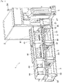
Fig. 1 is a perspective view schematically illustrating a configuration of a component supply unit storage and retrieval system of a first embodiment. -
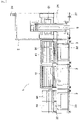
Fig. 2 is a front view schematically illustrating a configuration of the component supply unit storage and retrieval system of the first embodiment. -
Fig. 3 is a functional block diagram illustrating a configuration of control in the first embodiment. -
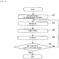
Fig. 4 is a diagram illustrating an operation flow for describing a control operation of a storage and retrieval control section in the first embodiment. -
Fig. 5 is a plan view schematically illustrating a component supply unit storage and retrieval system of a second embodiment. - A configuration of component supply unit storage and retrieval system 1 of a first embodiment will be described with reference to the configuration diagrams of
Figs. 1 and2 , and the functional block diagram ofFig. 3 . Storage and retrieval system 1 corresponds to a loading operation for loadingcomponent supply unit 92 withcomponent container 91 and related operations before and after the loading operation. Storage and retrieval system 1 is configured to includeunit warehouse 2,storage holding base 3, unit storages (41, 44), and storage andretrieval robot 5. -
Component container 91 is loaded incomponent supply unit 92 while containing multiple components.Component supply unit 92 is used when supplying the components contained incomponent container 91 in a mounting operation performed bycomponent mounter 98. Identification codes indicating each type or individual are attached tocomponent container 91 andcomponent supply unit 92. The identification code ofcomponent container 91 includes information indicating the type of the component contained incomponent container 91. As the identification code, a barcode, a two-dimensional code, or the like is used. Whencomponent supply unit 92 is loaded withcomponent container 91, the identification codes of both are read by the code reader. As a result, load information V (seeFig. 3 ) associating an individual ofcomponent container 91 with an individual ofcomponent supply unit 92, which is loaded withcomponent container 91, is created. - As
component container 91, a tape reel can be exemplified, and ascomponent supply unit 92, an integral type feeder device in which the tape reel is directly loaded can be exemplified. A carrier tape in which multiple components are sealed at a predetermined pitch is wound and held on the tape reel. The feeder device is installed oncomponent mounter 98 in a form to which the tape reel is loaded. The feeder device supplies the component to a component mounting tool ofcomponent mounter 98 by pulling out the carrier tape from the tape reel and sending the carrier tape to a component pick up position. When the mounting operation of the component proceeds and the component of the tape reel is consumed, the entire feeder device is exchanged. - The feeder device is not limited to an integral type and may be a separate type. The separate type feeder device is configured to include a feeder main body portion having a feeding mechanism of the carrier tape and a reel cassette to which the tape reel is loaded. The feeder main body portion is permanently provided in
component mounter 98, and the separate reel cassette is disposed in the vicinity of the feeder main body portion. When the mounting operation of the component proceeds and the component of the tape reel is consumed, the reel cassette is exchanged. The reel cassette corresponds tocomponent supply unit 92 to whichcomponent container 91 is loaded. - Hereinafter, a case where
component supply unit 92 is an integral type feeder device and a tape reel serving ascomponent container 91 is already loaded will be described. A tray may be used ascomponent container 91, and a tray loading unit may be used ascomponent supply unit 92. -
Unit warehouse 2 storescomponent supply units 92 more thancomponent supply units 92 stored inunit storages Figs. 1 and2 ,unit warehouse 2 is formed in a large vertical rectangular parallelepiped shape.Unit warehouse 2 includes a storage andretrieval port 21 on a front face thereof. However, the configuration is not limited to this, a storage port and a retrieval port may be provided separately.Component supply unit 92, which is loaded withcomponent container 91, is stored from storage andretrieval port 21 by an operator. -
Upper section guide 26 extending in the left-right direction is provided on a lower portion of storage andretrieval port 21 on the front face ofunit warehouse 2.Lower section guide 27 extending in the left-right direction is provided on a lowermost portion of the front face ofunit warehouse 2.Upper section guide 26 andlower section guide 27 are formed in, for example, a protrusion shape protruding ahead or a groove shape opened upward. - As illustrated in
Fig. 3 , multiple storing positions,actuator 22, andcode reader 23 are provided inunit warehouse 2. Theactuator 22transfers component container 91 stored in storage andretrieval port 21 to a storing position, or transfers thecomponent container 91 in the storing position to storage andretrieval port 21.Actuator 22 is controlled bywarehouse control section 29. -
Code reader 23 reads the identification code attached to storedcomponent supply unit 92 and delivers the read result towarehouse control section 29. Therefore,warehouse control section 29 can recognize the individuals of all storedcomponent supply units 92 in association with the storing positions. Further,warehouse control section 29 can recognizecomponent container 91 loaded in each of thecomponent supply units 92 with reference to load informationV. Warning lamp 24 is provided on the right front side of the upper portion ofunit warehouse 2.Warehouse control section 29 controls the lighting of warninglamp 24 when an abnormality occurs or a failure occurs and notifies an operator of the same. - As illustrated in
Figs. 1 and2 ,storage holding base 3 is disposed on the left side ofunit warehouse 2 adjacent to each other. However, the configuration is not limited to this,storage holding base 3 may be disposed on the right side ofunit warehouse 2.Storage holding base 3 holds unit storages 41 and 44 on the upper side.Storage holding base 3 is formed in a rectangular parallelepiped frame shape.Upper section guide 32 extending in the left-right direction is provided on an upper portion of the front face ofstorage holding base 3.Lower section guide 33 extending in the left-right direction is provided on a lower portion of the front face ofstorage holding base 3.Upper section guide 32 andLower section guide 33 are disposed at the same height asupper section guide 26 andlower section guide 27 ofunit warehouse 2, and are formed in the same shape. -
Storage holding base 3 is capable of being additionally installed. Whenstorage holding base 3 is additionally installed, multiplestorage holding bases 3 are disposed adjacent to each other in the left-right direction. Further, multiplestorage holding bases 3 may be disposed so as to be dispersed on both the left and right sides ofunit warehouse 2. As a result, multiple upper section guides 32 are connected in the left-right direction and are further connected to upper section guide 26 ofunit warehouse 2 to form a long movement guide. Similarly, multiple lower section guides 33 are connected in the left-right direction and are further connected to lowersection guide 27 ofunit warehouse 2 to form a long movement guide. - Full width unit storages 41 are held on the right side and center on the upper side of
storage holding bases 3 among threestorage holding bases 3 illustrated inFigs. 1 and2 . Further, two half width unit storages 44 are held on the upper side ofstorage holding base 3 on the left side. The width dimension of fullwidth unit storage 41 is slightly smaller than the width dimension ofcomponent mounter 98. The width dimension of halfwidth unit storage 44 is substantially half the width dimension of fullwidth unit storage 41. - Unit storages (41, 44) stores multiple
component supply units 92. Multiple storage slots set-up in the left-right direction are formed on the bottom face of the inner side of unit storages (41, 44). Storage slot is formed with, for example, a groove extending in the front-rear direction, into whichcomponent supply unit 92 is inserted from the front side and stored. InFigs. 1 and2 , onecomponent supply unit 92 is illustrated in fullwidth unit storage 41 on the right side, and in actuality, multiplecomponent supply units 92 are stored side by side in the left-right direction. The number of storage slots of halfwidth unit storage 44 is half of the number of storage slots of fullwidth unit storage 41. - Full
width unit storage 41 is installed oncomponent mounter 98 and serves as a main portion of a component supply device. Similarly, two half width unit storages 44 are installed oncomponent mounter 98 to serve as a main portion of the component supply device. However, the configuration is not limited to this, unit storages (41, 44) may not be installed oncomponent mounter 98 but may collectively perform a set-up work, transportation, or the like of stored multiplecomponent supply units 92 to improve efficiency. - Storage and
retrieval robot 5 delivers set-upcomponent supply unit 92 loaded withcomponent container 91 between unit storages (41, 44) andunit warehouse 2. Storage andretrieval robot 5 is formed so as to be longitudinally long. Storage andretrieval robot 5 includes a guide member and a movement drive section on the rear side. The guide member engages with the movement guide including multiple section guides (26, 27, 32, 33). As a result, the entire weight of storage andretrieval robot 5 is supported by the movement guide, and a movement direction is predefined. The movement drive section operates, for example, by using a non-contact power supply device or a battery (not illustrated) as a power source. The movement drive section is configured to include, for example, a combination of traveling wheels and a drive motor, or a movement mechanism to which a linear motor is applied. As a result, storage andretrieval robot 5 is moved on the front side of unit storages (41, 44) andunit warehouse 2 along the movement guide. - Storage and
retrieval robot 5 further includes a unit holding space and a unit operating mechanism. The unit holding space is a space defined in the inner portion of storage andretrieval robot 5 and opened rearward. The unit holding space temporarily holdscomponent supply unit 92 to be conveyed. The unit operating mechanism deliverscomponent supply unit 92 between the unit holding space and unit storages (41, 44), and between the unit holding space and storage andretrieval port 21 ofunit warehouse 2. At this time, since the height of storage andretrieval robot 5 is appropriately maintained by the engagement of the guide member and the movement guide, the delivering operation is stabilized. Storage andretrieval robot 5 is controlled by storage andretrieval control section 8. - Next, a configuration related to control of storage and retrieval system 1 will be described. As illustrated in
Fig. 3 , storage andretrieval control section 8 is communicatively connected to streamliningprocessing section 95.Streamlining processing section 95 is communicatively connected toline control section 96. Further,line control section 96 is communicatively connected to each of multiple types of board work machines constitutingboard work line 97.Board work line 97 is a production line for mounting components on a board to mass-produce a board product.Component mounter 98 constitutingboard work line 97 is installed with set-up unit storages (41, 44) to enable the supply of the components. -
Streamlining processing section 95 performs a streamlined process for improving the efficiency of the operation inboard work line 97. As part of the streamlined process, streamliningprocessing section 95 optimizes the storage positions of multiplecomponent supply units 92 in unit storages (41, 44) in order to improve the efficiency of the mounting operation of the components incomponent mounter 98. This streamlined process is also referred to as an optimization process, and various well-known techniques can be applied.Line control section 96 controls the operation ofboard work line 97 based on the result of the streamlined process received from streamliningprocessing section 95. - On the other hand, storage and
retrieval control section 8 is communicatively connected towarehouse control section 29 ofunit warehouse 2. Further, storage andretrieval control section 8 controls storage andretrieval robot 5. Further, loadinformation memory section 81 attached to storage andretrieval control section 8 stores load information V. Storage andretrieval control section 8 includes a man-machine interface (an input section, a display section, a wireless communication section, or the like) for exchanging information with the operator. - Load information V or other various information are appropriately transmitted and received between each of the control elements described above. Therefore, storage and
retrieval control section 8 can enableunit warehouse 2 andcomponent mounter 98 to share load information V. Further, all of each control element described above needs not to be independent hardware. For example, storage andretrieval control section 8 andwarehouse control section 29 may be achieved by different software in one computer device. Further, for example, storage andretrieval control section 8 may be achieved as a partial function of streamliningprocessing section 95. Further, the communication connection or the information transmission described above may be performed by using a wireless communication device. The control functions of storage andretrieval control section 8 and the like will be described in detail in the following description of operations. - Next, the operation of storage and retrieval system 1 will be described with reference to
Fig. 4 . In step S1 inFig. 4 , storage andretrieval control section 8 acquires the result of the streamlined process from streamliningprocessing section 95. The result of the streamlined process includes an identification code ofcomponent supply unit 92 to be used and information about the storage position in unit storages (41, 44). The information about the storage position is represented by, for example, a slot number indicating a position of the storage slot. - In the next step S2, storage and
retrieval control section 8 provides the identification code ofcomponent supply unit 92 to be used towarehouse control section 29 through the command.Warehouse control section 29 controls actuator 22 in accordance with the command and transferscomponent supply unit 92 to storage andretrieval port 21. In the next step S3, storage andretrieval control section 8 commands storage andretrieval robot 5 to conveycomponent supply unit 92. Storage andretrieval robot 5 conveyscomponent supply unit 92 at storage andretrieval port 21 to unit storages (41, 44) in accordance with the command. - In the next step S4, storage and
retrieval control section 8 provides the storage positions in unit storages (41, 44) to storage andretrieval robot 5 through the command. Storage andretrieval robot 5 storescomponent supply unit 92 in the commanded storage position. In the next step S5, storage andretrieval control section 8 determines whether allcomponent supply units 92 included in the result of the streamlined process are aligned in unit storages (41, 44). Thereafter, while allcomponent supply units 92 are not aligned, storage andretrieval control section 8 repeatedly executes steps S2 to S5. - When all
component supply units 92 are aligned by the repetition of the execution, the operation flow ends. At this point, unit storages (41, 44) are ready for use. The operator transports and installs one fullwidth unit storage 41 or two half width unit storages 44 tocomponent mounter 98. In one example of this installing operation, first, the operator connects a carriage (not illustrated) for transportation to the opposite side of storage andretrieval robot 5 atstorage holding base 3. Secondly, the operator pulls out unit storages (41, 44) fromstorage holding base 3, transfers unit storages (41, 44) to the carriage, and transports unit storages (41, 44) tocomponent mounter 98. Third, the operator connects the carriage to an installation position ofcomponent mounter 98. Finally, the operator transfers unit storages (41, 44) from the carriage tocomponent mounter 98. As a result,component mounter 98 is ready to supply the components. At this time, load information V is shared bycomponent mounter 98 by the communication or the like. - In component supply unit storage and retrieval system 1 of the first embodiment, storage and
retrieval robot 5 automatically performs an operation of retrieving multiplecomponent supply units 92 fromunit warehouse 2 and storing the same in unit storages (41, 44). Thereafter, the multiplecomponent supply units 92 stored in unit storages (41, 44) are collectively utilized in a subsequent set-up work or are collectively installed incomponent mounter 98. Therefore, it is possible to streamline the set-up work as compared with the conventional technique in whichcomponent supply units 92 are set-up one by one. - Further, storage and
retrieval control section 8 controls for selecting multiplecomponent supply units 92 which are retrieved fromunit warehouse 2 and further controls the storage positions of retrieved multiplecomponent supply units 92 in unit storages (41, 44), based on the result of the streamlined process. According to this configuration, subsequent to the streamlined process, it is possible to timely perform the set-up of unit storages (41, 44) to be installed incomponent mounter 98. Further, since the storage positions of multiplecomponent supply units 92 in the unit storages (41, 44) are automatically controlled, there would be no possibility that the storage positions are erroneous. Further, sinceunit warehouse 2 for storingcomponent supply unit 92 andstorage holding base 3 for storingcomponent supply unit 92 in unit storages (41, 44) are disposed adjacent to each other, a space-saving system configuration is achieved. - Next, with reference to
Fig. 5 , a description will be given of storage andretrieval system 1A of a second embodiment that differs from the first embodiment. As illustrated inFig. 5 , in the second embodiment, travelingpath 65 andconveyance vehicle 66 are added to the configuration of the first embodiment. - Traveling
path 65 is laid from the rear side ofstorage holding base 3 on the left side toboard work line 97.Storage holding base 3 on the left side also serves as a carry-out station for carrying outcomponent supply unit 92, which is loaded withcomponent container 91, towardcomponent mounter 98, and a carry-in station for carrying incomponent supply unit 92 that has been used incomponent mounter 98.Conveyance vehicle 66 travels on travelingpath 65 in accordance with a wireless command from storage andretrieval control section 8 and also loads and unloads halfwidth unit storage 44.Conveyance vehicle 66 appropriately reports a progress status of the conveyance operation to storage andretrieval control section 8. A standby position ofconveyance vehicle 66 is set on the rear side ofstorage holding base 3 on the left side (illustrated inFig. 5 ). Travelingpath 65 may be laid over multiple board work lines 97 so thatmultiple conveyance vehicles 66 may travel while avoiding collisions. Further,conveyance vehicle 66 may be an AGV of a type in which physical travelingpath 65 is unnecessary and travels by referring to information about the traveling path on map data. - In the above configuration,
conveyance vehicle 66 removes halfwidth unit storage 44 ready to be used fromstorage holding base 3 and loads the same. Next,conveyance vehicle 66 travels tocomponent mounter 98, conveys halfwidth unit storage 44, and installs the same incomponent mounter 98. Alternatively,conveyance vehicle 66 delivers halfwidth unit storage 44 to the operator in the vicinity ofcomponent mounter 98. Further,conveyance vehicle 66 conveys second halfwidth unit storage 44 in the same manner. According to the second embodiment, in addition to the storage ofcomponent supply unit 92 in halfwidth unit storage 44, automation of the transporting operation of halfwidth unit storage 44 is achieved. - In the second embodiment,
conveyance vehicle 66 may return halfwidth unit storage 44 that has been used incomponent mounter 98 tostorage holding base 3. Thereafter,component supply unit 92 is returned tounit warehouse 2 and stored. At this time, load information V is shared withunit warehouse 2 by the communication or the like. Further,conveyance vehicle 66 conveys halfwidth unit storage 44 twice due to performance constraints. However, by increasing the size and improving the performance ofconveyance vehicle 66, it is possible to convey fullwidth unit storage 41. Further, the first and second embodiments are capable of various applications and modifications. -
- 1, 1A: component supply unit storage and retrieval system
- 2: unit warehouse
- 21: storage and retrieval port
- 22: actuator
- 23: code reader
- 26: upper section guide
- 27: lower section guide
- 29: warehouse control section
- 3: storage holding base
- 32: upper section guide
- 33: lower section guide
- 41: full width unit storage
- 44: half width unit storage
- 5: storage and retrieval robot
- 66: conveyance vehicle
- 8: storage and retrieval control section
- 81: load information memory section
- 91: component container
- 92: component supply unit
- 95: streamlining processing section
- 98: component mounter
- V: load information
Claims (9)
- A component supply unit storage and retrieval system comprising:a unit storage configured to store multiple component supply units used when multiple components are supplied to a component mounter;a storage holding base configured to hold the unit storage;a unit warehouse configured to store the component supply units more than the unit storage; anda storage and retrieval robot configured to deliver the component supply unit between the unit storage and the unit warehouse.
- The component supply unit storage and retrieval system according to claim 1, further comprising:a movement guide provided from the storage holding base to the unit warehouse,wherein the storage and retrieval robot moves along the movement guide.
- The component supply unit storage and retrieval system according to claim 2,
wherein the movement guide is configured such that section guides provided in each of the storage holding base and the unit warehouse are lined up in a movement direction of the storage and retrieval robot. - The component supply unit storage and retrieval system according to claim 3,
wherein the storage holding base is capable of being additionally installed. - The component supply unit storage and retrieval system according to any one of claims 1 to 4,
wherein the unit storage is configured to be installed in the component mounter. - The component supply unit storage and retrieval system according to claim 5, further comprising:
a conveyance vehicle configured to convey the unit storage that stores the multiple component supply units to the component mounter. - The component supply unit storage and retrieval system according to claim 5 or 6, further comprising:
a storage and retrieval control section configured to control for selecting multiple component supply units which are retrieved from the unit warehouse and control storage positions of the retrieved multiple component supply units in the unit storage, based on a result of a streamlined process of optimizing the storage positions of the multiple component supply units in the unit storage, in order to streamline a mounting operation of the component in the component mounter. - The component supply unit storage and retrieval system according to claim 7, further comprising:
a load information memory section configured to store load information in which an individual of the component containers and an individual of the component supply units, which are loaded with the component container, are associated with each other. - The component supply unit storage and retrieval system according to any one of claims 1 to 8,
wherein the component supply unit is a feeder device loaded with a tape reel in which a carrier tape containing the multiple components is wound, or is a reel cassette loaded with the tape reel and formed separately from a feeder main body portion having a feeding mechanism of the carrier tape.
Applications Claiming Priority (1)
| Application Number | Priority Date | Filing Date | Title |
|---|---|---|---|
| PCT/JP2020/000932 WO2021144865A1 (en) | 2020-01-14 | 2020-01-14 | Component supply unit storage and retrieval system |
Publications (3)
| Publication Number | Publication Date |
|---|---|
| EP4093174A1 true EP4093174A1 (en) | 2022-11-23 |
| EP4093174A4 EP4093174A4 (en) | 2023-01-04 |
| EP4093174B1 EP4093174B1 (en) | 2024-10-23 |
Family
ID=76863960
Family Applications (1)
| Application Number | Title | Priority Date | Filing Date |
|---|---|---|---|
| EP20914125.8A Active EP4093174B1 (en) | 2020-01-14 | 2020-01-14 | Component supply unit storage and retrieval system |
Country Status (5)
| Country | Link |
|---|---|
| US (1) | US12221283B2 (en) |
| EP (1) | EP4093174B1 (en) |
| JP (3) | JP7633184B2 (en) |
| CN (1) | CN114762471B (en) |
| WO (1) | WO2021144865A1 (en) |
Family Cites Families (45)
| Publication number | Priority date | Publication date | Assignee | Title |
|---|---|---|---|---|
| US3058545A (en) * | 1959-08-18 | 1962-10-16 | Frank L Morehouse | Dispensing mechanism |
| JPS63237256A (en) * | 1987-03-26 | 1988-10-03 | Matsushita Electric Ind Co Ltd | Automatic cassette exchange device |
| JP2682998B2 (en) * | 1987-11-16 | 1997-11-26 | キヤノン株式会社 | Goods distribution system |
| JP2674066B2 (en) | 1988-03-04 | 1997-11-05 | 松下電器産業株式会社 | Component mounting device |
| JP2792956B2 (en) * | 1989-11-10 | 1998-09-03 | 三洋電機株式会社 | Parts supply system |
| US5321885A (en) * | 1991-03-18 | 1994-06-21 | Fujitsu Limited | Method and apparatus for manufacturing printed wiring boards |
| JP3238747B2 (en) * | 1992-06-18 | 2001-12-17 | パイオニア株式会社 | Adaptive video recording / playback system, adaptive video playback system, adaptive video recording / playback method, and adaptive video playback method |
| JPH066084A (en) | 1992-06-19 | 1994-01-14 | Olympus Optical Co Ltd | Automatic electronic part installation equipment |
| JPH06190646A (en) * | 1992-12-28 | 1994-07-12 | Matsushita Electric Ind Co Ltd | Taping parts feeding cassette |
| JPH0890356A (en) * | 1994-09-21 | 1996-04-09 | Fujitsu Ltd | Assembly line |
| JP3483343B2 (en) * | 1995-04-25 | 2004-01-06 | ヤマハ発動機株式会社 | Component supply device for mounting machine |
| JP2002249207A (en) * | 2001-02-23 | 2002-09-03 | Samii Kk | Parts carriage and storage system |
| US6871116B2 (en) * | 2002-10-17 | 2005-03-22 | Vertique, Inc. | Determining pallet case configurations for placement by a robot |
| US8037996B2 (en) * | 2009-01-05 | 2011-10-18 | Asm Assembly Automation Ltd | Transfer apparatus for handling electronic components |
| JP5476288B2 (en) | 2010-12-22 | 2014-04-23 | 株式会社日立製作所 | External setup system for component mounting machines |
| JP5780779B2 (en) * | 2011-02-28 | 2015-09-16 | 富士機械製造株式会社 | Reel component supply method and reel component supply system |
| KR101229981B1 (en) * | 2011-06-17 | 2013-02-05 | 에스티에스 주식회사 | Storing Apparatus for Managing Surface Mount Devices and Method for Managing Surface Mount Devices |
| JP5963863B2 (en) | 2012-07-13 | 2016-08-03 | 富士機械製造株式会社 | Component mounting system |
| JP6049037B2 (en) * | 2013-02-04 | 2016-12-21 | 富士機械製造株式会社 | Cassette feeder replacement system for component mounters |
| JP6266621B2 (en) | 2013-08-06 | 2018-01-24 | 富士機械製造株式会社 | Preparatory work support system |
| DE102013019368A1 (en) * | 2013-11-18 | 2015-05-21 | Grenzebach Maschinenbau Gmbh | Method and device for the largely automated assembly of goods deliveries in warehouses |
| WO2016142987A1 (en) * | 2015-03-06 | 2016-09-15 | 富士機械製造株式会社 | Reel holding device and reel replacement device |
| US10772249B2 (en) * | 2015-03-18 | 2020-09-08 | Mycronic AB | Method, system and device for providing and changing information related to an SMT job |
| CN107006144B (en) * | 2015-04-23 | 2019-05-17 | 雅马哈发动机株式会社 | Component mounting machine, control method of component mounting machine, recording medium, and component mounting system |
| US10820459B2 (en) * | 2015-08-25 | 2020-10-27 | Fuji Corporation | Component mounting line |
| JP2017052540A (en) * | 2015-09-09 | 2017-03-16 | 株式会社岡村製作所 | container |
| JP6378232B2 (en) * | 2016-03-17 | 2018-08-22 | ファナック株式会社 | Stacking pattern calculation device and stacking device for stacking multiple types of articles |
| US11470751B2 (en) * | 2016-07-08 | 2022-10-11 | Fuji Corporation | Component-mounting system and management device |
| JP6870999B2 (en) * | 2017-01-30 | 2021-05-12 | 株式会社Fuji | Calibration parts supply unit, its automatic replacement system, and parts mounting machine |
| WO2018157231A1 (en) * | 2017-03-01 | 2018-09-07 | Synergie Medicale Brg Inc. | System for automatic filling of medication organizers |
| JP6554672B2 (en) * | 2017-03-27 | 2019-08-07 | パナソニックIpマネジメント株式会社 | Parts container management device, parts container storage, and parts storage instruction method |
| JP6884950B2 (en) | 2017-05-12 | 2021-06-09 | 株式会社Fuji | Component mounting system |
| WO2018235576A1 (en) * | 2017-06-20 | 2018-12-27 | 三菱電機株式会社 | Parts storing device |
| FR3075767B1 (en) * | 2017-12-21 | 2021-10-01 | Solystic | HETEROGENOUS OBJECTS PALETTIZATION PROCESS |
| CN111587614B (en) | 2018-01-19 | 2021-09-10 | 株式会社富士 | Storage device and storage method with reel |
| JP7494414B2 (en) * | 2018-04-27 | 2024-06-04 | トーヨーカネツ株式会社 | Automatic Shipping Device |
| EP3927131B1 (en) * | 2019-02-12 | 2025-07-30 | Fuji Corporation | Component type management device |
| JP7210741B2 (en) * | 2019-07-22 | 2023-01-23 | 株式会社Fuji | Tray type parts feeder |
| US12453069B2 (en) * | 2019-11-25 | 2025-10-21 | Fuji Corporation | Warehouse system |
| CN114846921B (en) * | 2020-01-14 | 2024-03-05 | 株式会社富士 | Production change adjustment system for component supply unit |
| JP7350895B2 (en) * | 2020-01-14 | 2023-09-26 | 株式会社Fuji | Parts supply unit setup system |
| US12207412B2 (en) * | 2020-01-14 | 2025-01-21 | Fuji Corporation | Article transport system |
| EP4237356A1 (en) * | 2020-10-30 | 2023-09-06 | Berkshire Grey Operating Company, Inc. | Systems and methods for sku induction, decanting and automated- eligibility estimation |
| AT524439B1 (en) * | 2021-02-04 | 2022-06-15 | Knapp Ag | System for separating and identifying articles |
| JP2023160449A (en) * | 2022-04-22 | 2023-11-02 | 株式会社Fuji | parts supply device |
-
2020
- 2020-01-14 EP EP20914125.8A patent/EP4093174B1/en active Active
- 2020-01-14 JP JP2021571096A patent/JP7633184B2/en active Active
- 2020-01-14 WO PCT/JP2020/000932 patent/WO2021144865A1/en not_active Ceased
- 2020-01-14 CN CN202080082079.0A patent/CN114762471B/en active Active
- 2020-01-14 US US17/791,416 patent/US12221283B2/en active Active
-
2024
- 2024-10-01 JP JP2024172517A patent/JP7738142B2/en active Active
-
2025
- 2025-09-01 JP JP2025144548A patent/JP2025176101A/en active Pending
Also Published As
| Publication number | Publication date |
|---|---|
| CN114762471B (en) | 2023-11-17 |
| JP7633184B2 (en) | 2025-02-19 |
| EP4093174A4 (en) | 2023-01-04 |
| JP2025176101A (en) | 2025-12-03 |
| US20230064045A1 (en) | 2023-03-02 |
| EP4093174B1 (en) | 2024-10-23 |
| WO2021144865A1 (en) | 2021-07-22 |
| JPWO2021144865A1 (en) | 2021-07-22 |
| US12221283B2 (en) | 2025-02-11 |
| JP7738142B2 (en) | 2025-09-11 |
| CN114762471A (en) | 2022-07-15 |
| JP2024177295A (en) | 2024-12-19 |
Similar Documents
| Publication | Publication Date | Title |
|---|---|---|
| US12432893B2 (en) | Component supply unit arrangement handling system | |
| US10589931B2 (en) | Hybrid modular storage fetching system | |
| US12617611B2 (en) | Inventory management method and system | |
| US20230345688A1 (en) | Component supply device | |
| US12453069B2 (en) | Warehouse system | |
| JP7383838B2 (en) | Parts storage system, parts storage and magazine preparation method | |
| CN111199331A (en) | Digital assembly production system based on digital performance management | |
| EP4093172B1 (en) | System for preparing component feed unit | |
| EP4093174B1 (en) | Component supply unit storage and retrieval system | |
| CN119079359A (en) | A storage transmission method and system | |
| CN119975613A (en) | An intelligent manufacturing method and system for automobile door cover parts combining AGV and vision guidance | |
| EP2117979A1 (en) | A method and a system for controlling an automatic flow of products |
Legal Events
| Date | Code | Title | Description |
|---|---|---|---|
| STAA | Information on the status of an ep patent application or granted ep patent |
Free format text: STATUS: THE INTERNATIONAL PUBLICATION HAS BEEN MADE |
|
| PUAI | Public reference made under article 153(3) epc to a published international application that has entered the european phase |
Free format text: ORIGINAL CODE: 0009012 |
|
| STAA | Information on the status of an ep patent application or granted ep patent |
Free format text: STATUS: REQUEST FOR EXAMINATION WAS MADE |
|
| 17P | Request for examination filed |
Effective date: 20220714 |
|
| AK | Designated contracting states |
Kind code of ref document: A1 Designated state(s): AL AT BE BG CH CY CZ DE DK EE ES FI FR GB GR HR HU IE IS IT LI LT LU LV MC MK MT NL NO PL PT RO RS SE SI SK SM TR |
|
| A4 | Supplementary search report drawn up and despatched |
Effective date: 20221202 |
|
| RIC1 | Information provided on ipc code assigned before grant |
Ipc: H05K 13/08 20060101ALI20221128BHEP Ipc: H05K 13/02 20060101AFI20221128BHEP |
|
| DAV | Request for validation of the european patent (deleted) | ||
| DAX | Request for extension of the european patent (deleted) | ||
| P01 | Opt-out of the competence of the unified patent court (upc) registered |
Effective date: 20230328 |
|
| STAA | Information on the status of an ep patent application or granted ep patent |
Free format text: STATUS: EXAMINATION IS IN PROGRESS |
|
| 17Q | First examination report despatched |
Effective date: 20230918 |
|
| GRAP | Despatch of communication of intention to grant a patent |
Free format text: ORIGINAL CODE: EPIDOSNIGR1 |
|
| GRAP | Despatch of communication of intention to grant a patent |
Free format text: ORIGINAL CODE: EPIDOSNIGR1 |
|
| STAA | Information on the status of an ep patent application or granted ep patent |
Free format text: STATUS: GRANT OF PATENT IS INTENDED |
|
| GRAJ | Information related to disapproval of communication of intention to grant by the applicant or resumption of examination proceedings by the epo deleted |
Free format text: ORIGINAL CODE: EPIDOSDIGR1 |
|
| INTG | Intention to grant announced |
Effective date: 20240614 |
|
| STAA | Information on the status of an ep patent application or granted ep patent |
Free format text: STATUS: EXAMINATION IS IN PROGRESS |
|
| GRAP | Despatch of communication of intention to grant a patent |
Free format text: ORIGINAL CODE: EPIDOSNIGR1 |
|
| STAA | Information on the status of an ep patent application or granted ep patent |
Free format text: STATUS: GRANT OF PATENT IS INTENDED |
|
| INTC | Intention to grant announced (deleted) | ||
| INTG | Intention to grant announced |
Effective date: 20240719 |
|
| GRAS | Grant fee paid |
Free format text: ORIGINAL CODE: EPIDOSNIGR3 |
|
| GRAA | (expected) grant |
Free format text: ORIGINAL CODE: 0009210 |
|
| STAA | Information on the status of an ep patent application or granted ep patent |
Free format text: STATUS: THE PATENT HAS BEEN GRANTED |
|
| AK | Designated contracting states |
Kind code of ref document: B1 Designated state(s): AL AT BE BG CH CY CZ DE DK EE ES FI FR GB GR HR HU IE IS IT LI LT LU LV MC MK MT NL NO PL PT RO RS SE SI SK SM TR |
|
| REG | Reference to a national code |
Ref country code: GB Ref legal event code: FG4D |
|
| REG | Reference to a national code |
Ref country code: CH Ref legal event code: EP |
|
| REG | Reference to a national code |
Ref country code: DE Ref legal event code: R096 Ref document number: 602020040096 Country of ref document: DE |
|
| REG | Reference to a national code |
Ref country code: IE Ref legal event code: FG4D |
|
| REG | Reference to a national code |
Ref country code: LT Ref legal event code: MG9D |
|
| REG | Reference to a national code |
Ref country code: NL Ref legal event code: MP Effective date: 20241023 |
|
| REG | Reference to a national code |
Ref country code: AT Ref legal event code: MK05 Ref document number: 1735932 Country of ref document: AT Kind code of ref document: T Effective date: 20241023 |
|
| PG25 | Lapsed in a contracting state [announced via postgrant information from national office to epo] |
Ref country code: NL Free format text: LAPSE BECAUSE OF FAILURE TO SUBMIT A TRANSLATION OF THE DESCRIPTION OR TO PAY THE FEE WITHIN THE PRESCRIBED TIME-LIMIT Effective date: 20241023 |
|
| PG25 | Lapsed in a contracting state [announced via postgrant information from national office to epo] |
Ref country code: NL Free format text: LAPSE BECAUSE OF FAILURE TO SUBMIT A TRANSLATION OF THE DESCRIPTION OR TO PAY THE FEE WITHIN THE PRESCRIBED TIME-LIMIT Effective date: 20241023 |
|
| PG25 | Lapsed in a contracting state [announced via postgrant information from national office to epo] |
Ref country code: IS Free format text: LAPSE BECAUSE OF FAILURE TO SUBMIT A TRANSLATION OF THE DESCRIPTION OR TO PAY THE FEE WITHIN THE PRESCRIBED TIME-LIMIT Effective date: 20250223 Ref country code: HR Free format text: LAPSE BECAUSE OF FAILURE TO SUBMIT A TRANSLATION OF THE DESCRIPTION OR TO PAY THE FEE WITHIN THE PRESCRIBED TIME-LIMIT Effective date: 20241023 Ref country code: PT Free format text: LAPSE BECAUSE OF FAILURE TO SUBMIT A TRANSLATION OF THE DESCRIPTION OR TO PAY THE FEE WITHIN THE PRESCRIBED TIME-LIMIT Effective date: 20250224 |
|
| PG25 | Lapsed in a contracting state [announced via postgrant information from national office to epo] |
Ref country code: FI Free format text: LAPSE BECAUSE OF FAILURE TO SUBMIT A TRANSLATION OF THE DESCRIPTION OR TO PAY THE FEE WITHIN THE PRESCRIBED TIME-LIMIT Effective date: 20241023 |
|
| PG25 | Lapsed in a contracting state [announced via postgrant information from national office to epo] |
Ref country code: BG Free format text: LAPSE BECAUSE OF FAILURE TO SUBMIT A TRANSLATION OF THE DESCRIPTION OR TO PAY THE FEE WITHIN THE PRESCRIBED TIME-LIMIT Effective date: 20241023 |
|
| PG25 | Lapsed in a contracting state [announced via postgrant information from national office to epo] |
Ref country code: ES Free format text: LAPSE BECAUSE OF FAILURE TO SUBMIT A TRANSLATION OF THE DESCRIPTION OR TO PAY THE FEE WITHIN THE PRESCRIBED TIME-LIMIT Effective date: 20241023 |
|
| PG25 | Lapsed in a contracting state [announced via postgrant information from national office to epo] |
Ref country code: NO Free format text: LAPSE BECAUSE OF FAILURE TO SUBMIT A TRANSLATION OF THE DESCRIPTION OR TO PAY THE FEE WITHIN THE PRESCRIBED TIME-LIMIT Effective date: 20250123 |
|
| PG25 | Lapsed in a contracting state [announced via postgrant information from national office to epo] |
Ref country code: LV Free format text: LAPSE BECAUSE OF FAILURE TO SUBMIT A TRANSLATION OF THE DESCRIPTION OR TO PAY THE FEE WITHIN THE PRESCRIBED TIME-LIMIT Effective date: 20241023 Ref country code: AT Free format text: LAPSE BECAUSE OF FAILURE TO SUBMIT A TRANSLATION OF THE DESCRIPTION OR TO PAY THE FEE WITHIN THE PRESCRIBED TIME-LIMIT Effective date: 20241023 Ref country code: GR Free format text: LAPSE BECAUSE OF FAILURE TO SUBMIT A TRANSLATION OF THE DESCRIPTION OR TO PAY THE FEE WITHIN THE PRESCRIBED TIME-LIMIT Effective date: 20250124 |
|
| PG25 | Lapsed in a contracting state [announced via postgrant information from national office to epo] |
Ref country code: PL Free format text: LAPSE BECAUSE OF FAILURE TO SUBMIT A TRANSLATION OF THE DESCRIPTION OR TO PAY THE FEE WITHIN THE PRESCRIBED TIME-LIMIT Effective date: 20241023 |
|
| PG25 | Lapsed in a contracting state [announced via postgrant information from national office to epo] |
Ref country code: RS Free format text: LAPSE BECAUSE OF FAILURE TO SUBMIT A TRANSLATION OF THE DESCRIPTION OR TO PAY THE FEE WITHIN THE PRESCRIBED TIME-LIMIT Effective date: 20250123 |
|
| PG25 | Lapsed in a contracting state [announced via postgrant information from national office to epo] |
Ref country code: SM Free format text: LAPSE BECAUSE OF FAILURE TO SUBMIT A TRANSLATION OF THE DESCRIPTION OR TO PAY THE FEE WITHIN THE PRESCRIBED TIME-LIMIT Effective date: 20241023 |
|
| PG25 | Lapsed in a contracting state [announced via postgrant information from national office to epo] |
Ref country code: DK Free format text: LAPSE BECAUSE OF FAILURE TO SUBMIT A TRANSLATION OF THE DESCRIPTION OR TO PAY THE FEE WITHIN THE PRESCRIBED TIME-LIMIT Effective date: 20241023 |
|
| PG25 | Lapsed in a contracting state [announced via postgrant information from national office to epo] |
Ref country code: EE Free format text: LAPSE BECAUSE OF FAILURE TO SUBMIT A TRANSLATION OF THE DESCRIPTION OR TO PAY THE FEE WITHIN THE PRESCRIBED TIME-LIMIT Effective date: 20241023 |
|
| PG25 | Lapsed in a contracting state [announced via postgrant information from national office to epo] |
Ref country code: RO Free format text: LAPSE BECAUSE OF FAILURE TO SUBMIT A TRANSLATION OF THE DESCRIPTION OR TO PAY THE FEE WITHIN THE PRESCRIBED TIME-LIMIT Effective date: 20241023 |
|
| REG | Reference to a national code |
Ref country code: DE Ref legal event code: R097 Ref document number: 602020040096 Country of ref document: DE |
|
| PG25 | Lapsed in a contracting state [announced via postgrant information from national office to epo] |
Ref country code: SK Free format text: LAPSE BECAUSE OF FAILURE TO SUBMIT A TRANSLATION OF THE DESCRIPTION OR TO PAY THE FEE WITHIN THE PRESCRIBED TIME-LIMIT Effective date: 20241023 |
|
| PG25 | Lapsed in a contracting state [announced via postgrant information from national office to epo] |
Ref country code: CZ Free format text: LAPSE BECAUSE OF FAILURE TO SUBMIT A TRANSLATION OF THE DESCRIPTION OR TO PAY THE FEE WITHIN THE PRESCRIBED TIME-LIMIT Effective date: 20241023 |
|
| PG25 | Lapsed in a contracting state [announced via postgrant information from national office to epo] |
Ref country code: IT Free format text: LAPSE BECAUSE OF FAILURE TO SUBMIT A TRANSLATION OF THE DESCRIPTION OR TO PAY THE FEE WITHIN THE PRESCRIBED TIME-LIMIT Effective date: 20241023 |
|
| PLBE | No opposition filed within time limit |
Free format text: ORIGINAL CODE: 0009261 |
|
| REG | Reference to a national code |
Ref country code: CH Ref legal event code: PL |
|
| STAA | Information on the status of an ep patent application or granted ep patent |
Free format text: STATUS: NO OPPOSITION FILED WITHIN TIME LIMIT |
|
| PG25 | Lapsed in a contracting state [announced via postgrant information from national office to epo] |
Ref country code: SE Free format text: LAPSE BECAUSE OF FAILURE TO SUBMIT A TRANSLATION OF THE DESCRIPTION OR TO PAY THE FEE WITHIN THE PRESCRIBED TIME-LIMIT Effective date: 20241023 |
|
| PG25 | Lapsed in a contracting state [announced via postgrant information from national office to epo] |
Ref country code: LU Free format text: LAPSE BECAUSE OF NON-PAYMENT OF DUE FEES Effective date: 20250114 Ref country code: MC Free format text: LAPSE BECAUSE OF FAILURE TO SUBMIT A TRANSLATION OF THE DESCRIPTION OR TO PAY THE FEE WITHIN THE PRESCRIBED TIME-LIMIT Effective date: 20241023 |
|
| GBPC | Gb: european patent ceased through non-payment of renewal fee |
Effective date: 20250123 |
|
| 26N | No opposition filed |
Effective date: 20250724 |
|
| PG25 | Lapsed in a contracting state [announced via postgrant information from national office to epo] |
Ref country code: GB Free format text: LAPSE BECAUSE OF NON-PAYMENT OF DUE FEES Effective date: 20250123 Ref country code: BE Free format text: LAPSE BECAUSE OF NON-PAYMENT OF DUE FEES Effective date: 20250131 |
|
| PG25 | Lapsed in a contracting state [announced via postgrant information from national office to epo] |
Ref country code: FR Free format text: LAPSE BECAUSE OF NON-PAYMENT OF DUE FEES Effective date: 20250131 |
|
| PG25 | Lapsed in a contracting state [announced via postgrant information from national office to epo] |
Ref country code: CH Free format text: LAPSE BECAUSE OF NON-PAYMENT OF DUE FEES Effective date: 20250131 |
|
| REG | Reference to a national code |
Ref country code: BE Ref legal event code: MM Effective date: 20250131 |
|
| PG25 | Lapsed in a contracting state [announced via postgrant information from national office to epo] |
Ref country code: IE Free format text: LAPSE BECAUSE OF NON-PAYMENT OF DUE FEES Effective date: 20250114 |
|
| PGFP | Annual fee paid to national office [announced via postgrant information from national office to epo] |
Ref country code: DE Payment date: 20251203 Year of fee payment: 7 |