EP4092272A1 - Compressor - Google Patents
Compressor Download PDFInfo
- Publication number
- EP4092272A1 EP4092272A1 EP21781414.4A EP21781414A EP4092272A1 EP 4092272 A1 EP4092272 A1 EP 4092272A1 EP 21781414 A EP21781414 A EP 21781414A EP 4092272 A1 EP4092272 A1 EP 4092272A1
- Authority
- EP
- European Patent Office
- Prior art keywords
- space
- shaft
- motor
- compressor
- plate
- Prior art date
- Legal status (The legal status is an assumption and is not a legal conclusion. Google has not performed a legal analysis and makes no representation as to the accuracy of the status listed.)
- Granted
Links
Images


Classifications
-
- H—ELECTRICITY
- H02—GENERATION; CONVERSION OR DISTRIBUTION OF ELECTRIC POWER
- H02K—DYNAMO-ELECTRIC MACHINES
- H02K21/00—Synchronous motors having permanent magnets; Synchronous generators having permanent magnets
- H02K21/12—Synchronous motors having permanent magnets; Synchronous generators having permanent magnets with stationary armatures and rotating magnets
- H02K21/24—Synchronous motors having permanent magnets; Synchronous generators having permanent magnets with stationary armatures and rotating magnets with magnets axially facing the armatures, e.g. hub-type cycle dynamos
-
- F—MECHANICAL ENGINEERING; LIGHTING; HEATING; WEAPONS; BLASTING
- F04—POSITIVE - DISPLACEMENT MACHINES FOR LIQUIDS; PUMPS FOR LIQUIDS OR ELASTIC FLUIDS
- F04B—POSITIVE-DISPLACEMENT MACHINES FOR LIQUIDS; PUMPS
- F04B35/00—Piston pumps specially adapted for elastic fluids and characterised by the driving means to their working members, or by combination with, or adaptation to, specific driving engines or motors, not otherwise provided for
- F04B35/04—Piston pumps specially adapted for elastic fluids and characterised by the driving means to their working members, or by combination with, or adaptation to, specific driving engines or motors, not otherwise provided for the means being electric
-
- F—MECHANICAL ENGINEERING; LIGHTING; HEATING; WEAPONS; BLASTING
- F04—POSITIVE - DISPLACEMENT MACHINES FOR LIQUIDS; PUMPS FOR LIQUIDS OR ELASTIC FLUIDS
- F04B—POSITIVE-DISPLACEMENT MACHINES FOR LIQUIDS; PUMPS
- F04B39/00—Component parts, details, or accessories, of pumps or pumping systems specially adapted for elastic fluids, not otherwise provided for in, or of interest apart from, groups F04B25/00 - F04B37/00
- F04B39/12—Casings; Cylinders; Cylinder heads; Fluid connections
- F04B39/121—Casings
-
- F—MECHANICAL ENGINEERING; LIGHTING; HEATING; WEAPONS; BLASTING
- F04—POSITIVE - DISPLACEMENT MACHINES FOR LIQUIDS; PUMPS FOR LIQUIDS OR ELASTIC FLUIDS
- F04B—POSITIVE-DISPLACEMENT MACHINES FOR LIQUIDS; PUMPS
- F04B39/00—Component parts, details, or accessories, of pumps or pumping systems specially adapted for elastic fluids, not otherwise provided for in, or of interest apart from, groups F04B25/00 - F04B37/00
- F04B39/12—Casings; Cylinders; Cylinder heads; Fluid connections
- F04B39/123—Fluid connections
-
- F—MECHANICAL ENGINEERING; LIGHTING; HEATING; WEAPONS; BLASTING
- F04—POSITIVE - DISPLACEMENT MACHINES FOR LIQUIDS; PUMPS FOR LIQUIDS OR ELASTIC FLUIDS
- F04C—ROTARY-PISTON, OR OSCILLATING-PISTON, POSITIVE-DISPLACEMENT MACHINES FOR LIQUIDS; ROTARY-PISTON, OR OSCILLATING-PISTON, POSITIVE-DISPLACEMENT PUMPS
- F04C23/00—Combinations of two or more pumps, each being of rotary-piston or oscillating-piston type, specially adapted for elastic fluids; Pumping installations specially adapted for elastic fluids; Multi-stage pumps specially adapted for elastic fluids
- F04C23/008—Hermetic pumps
-
- F—MECHANICAL ENGINEERING; LIGHTING; HEATING; WEAPONS; BLASTING
- F04—POSITIVE - DISPLACEMENT MACHINES FOR LIQUIDS; PUMPS FOR LIQUIDS OR ELASTIC FLUIDS
- F04C—ROTARY-PISTON, OR OSCILLATING-PISTON, POSITIVE-DISPLACEMENT MACHINES FOR LIQUIDS; ROTARY-PISTON, OR OSCILLATING-PISTON, POSITIVE-DISPLACEMENT PUMPS
- F04C29/00—Component parts, details or accessories of pumps or pumping installations, not provided for in groups F04C18/00 - F04C28/00
- F04C29/0042—Driving elements, brakes, couplings, transmissions specially adapted for pumps
- F04C29/0085—Prime movers
-
- F—MECHANICAL ENGINEERING; LIGHTING; HEATING; WEAPONS; BLASTING
- F04—POSITIVE - DISPLACEMENT MACHINES FOR LIQUIDS; PUMPS FOR LIQUIDS OR ELASTIC FLUIDS
- F04C—ROTARY-PISTON, OR OSCILLATING-PISTON, POSITIVE-DISPLACEMENT MACHINES FOR LIQUIDS; ROTARY-PISTON, OR OSCILLATING-PISTON, POSITIVE-DISPLACEMENT PUMPS
- F04C29/00—Component parts, details or accessories of pumps or pumping installations, not provided for in groups F04C18/00 - F04C28/00
- F04C29/06—Silencing
-
- H—ELECTRICITY
- H02—GENERATION; CONVERSION OR DISTRIBUTION OF ELECTRIC POWER
- H02K—DYNAMO-ELECTRIC MACHINES
- H02K7/00—Arrangements for handling mechanical energy structurally associated with dynamo-electric machines, e.g. structural association with mechanical driving motors or auxiliary dynamo-electric machines
- H02K7/14—Structural association with mechanical loads, e.g. with hand-held machine tools or fans
-
- F—MECHANICAL ENGINEERING; LIGHTING; HEATING; WEAPONS; BLASTING
- F04—POSITIVE - DISPLACEMENT MACHINES FOR LIQUIDS; PUMPS FOR LIQUIDS OR ELASTIC FLUIDS
- F04C—ROTARY-PISTON, OR OSCILLATING-PISTON, POSITIVE-DISPLACEMENT MACHINES FOR LIQUIDS; ROTARY-PISTON, OR OSCILLATING-PISTON, POSITIVE-DISPLACEMENT PUMPS
- F04C18/00—Rotary-piston pumps specially adapted for elastic fluids
- F04C18/30—Rotary-piston pumps specially adapted for elastic fluids having the characteristics covered by two or more of groups F04C18/02, F04C18/08, F04C18/22, F04C18/24, F04C18/48, or having the characteristics covered by one of these groups together with some other type of movement between co-operating members
- F04C18/34—Rotary-piston pumps specially adapted for elastic fluids having the characteristics covered by two or more of groups F04C18/02, F04C18/08, F04C18/22, F04C18/24, F04C18/48, or having the characteristics covered by one of these groups together with some other type of movement between co-operating members having the movement defined in group F04C18/08 or F04C18/22 and relative reciprocation between the co-operating members
- F04C18/356—Rotary-piston pumps specially adapted for elastic fluids having the characteristics covered by two or more of groups F04C18/02, F04C18/08, F04C18/22, F04C18/24, F04C18/48, or having the characteristics covered by one of these groups together with some other type of movement between co-operating members having the movement defined in group F04C18/08 or F04C18/22 and relative reciprocation between the co-operating members with vanes reciprocating with respect to the outer member
-
- H—ELECTRICITY
- H02—GENERATION; CONVERSION OR DISTRIBUTION OF ELECTRIC POWER
- H02K—DYNAMO-ELECTRIC MACHINES
- H02K2213/00—Specific aspects, not otherwise provided for and not covered by codes H02K2201/00 - H02K2211/00
- H02K2213/03—Machines characterised by numerical values, ranges, mathematical expressions or similar information
Definitions
- the present disclosure relates to a compressor.
- a compressor has a housing that defines a hollow portion extending in one direction (a height direction of the compressor), a compressor body that compresses a refrigerant and generates the compressed refrigerant, a shaft that extends in the same direction (the height direction of the compressor) as the housing and rotationally drives the compressor body, a motor that rotates the shaft, and a bearing portion that rotatably supports the shaft.
- the compressor body, the shaft, the motor, and the bearing portion are accommodated in the housing.
- the motor and the compressor body are disposed in a direction in which the shaft extends (the height direction of the compressor).
- the motor has the motor stator and the motor rotor.
- a radial gap motor and an axial gap motor are used as the motor.
- PTL 1 discloses a compressor in which a motor rotor configuring a motor is disposed above a compression portion (compressor body) and a motor stator configuring the motor above the motor rotor is disposed.
- PTL 1 discloses that a space is provided between the compression portion and the motor rotor.
- a coil end configuring the motor stator is disposed in the direction in which the shaft extends (the height direction of the compressor). For this reason, it is necessary to secure a space between the compressor body and the motor, and there is a possibility that the height of the compressor is high.
- the present disclosure is devised in order to solve the problem, and an object thereof is to provide a compressor of which a height can be lowered.
- a compressor including a housing that extends in an axial direction, a compressor body that is accommodated in a lower portion of the housing and generates a compressed refrigerant by compressing a refrigerant, a shaft that extends in the axial direction, penetrates the compressor body, is disposed from the lower portion of the housing to an upper portion of the housing, and rotationally drives the compressor body, a bearing portion that is disposed on an upper surface of the compressor body and rotatably supports the shaft, and a motor that is positioned above the bearing portion, is provided in the housing, and has a motor stator which surrounds an outer peripheral surface of an upper portion of the shaft and a motor rotor which is disposed on an upper surface side of the motor stator.
- a lower surface of the motor stator and an upper surface of the bearing portion are brought into contact with each other in the axial direction, and a flow channel space that extends in the axial direction and in which the compressed refrigerant flows is formed between the shaft and the motor stator.
- the height of the compressor can be lowered.
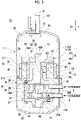
- FIG. 1 shows a rotary compressor as an example of the compressor 10.
- Fig. 1 also shows suction pipes 5 and 6 which are not components of the compressor 10.
- Fig. 2 is a cross-sectional view of the compressor 10 shown in Fig. 1 , which is taken along an A 1 -A 2 line direction.
- O 1 indicates an axis (hereinafter referred to as an "axis O 1 ") of a shaft 13
- X indicates a radial direction (hereinafter referred to as a “radial direction X”) of the shaft 13
- a Y-direction indicates an axial direction (hereinafter referred to as an "axial direction Y”), which is a direction (a height direction of the compressor 10) in which the axis O 1 extends.
- W1 indicates a width (hereinafter, referred to as a "width W1") of a lower space 62 in the radial direction
- W2 indicates a width (hereinafter, referred to as a "width W2”) of an upper space 63 in the radial direction.
- the compressor 10 includes a housing 11, a discharge pipe 12, the shaft 13, a lower bearing portion 15, a compressor body 16, an upper bearing portion 18 (bearing portion), a motor 19, and a flow channel space 20.
- the housing 11 is a closed type housing and extends in the axial direction Y.
- the housing 11 defines an internal space 11A extending in the axial direction Y.
- the housing 11 has a tubular portion 21, a bottom portion 22, and a lid portion 23.
- the tubular portion 21 is a cylindrical member of which both ends (an upper end and a lower end) disposed in the axial direction Y are open ends.
- the bottom portion 22 is connected to the tubular portion 21 in a state where a part thereof is inserted into a lower end side of the tubular portion 21. Accordingly, the bottom portion 22 closes the open end of the tubular portion 21 disposed on the lower end side. The bottom portion 22 protrudes downward from the lower end of the tubular portion 21.
- the lid portion 23 has a lid portion body 26 and a penetrating portion 27.
- the lid portion body 26 is connected to the tubular portion 21 in a state where a part thereof is inserted into an upper end side of the tubular portion 21. Accordingly, the lid portion body 26 closes the upper end of the tubular portion 21. The lid portion body 26 protrudes upward from the upper end of the tubular portion 21.
- the penetrating portion 27 is formed in the lid portion body 26 and penetrates the lid portion body 26 in the axial direction Y.
- the penetrating portion 27 has an axis formed at a position matching the axis O 1 of the shaft 13.
- the discharge pipe 12 is inserted into the penetrating portion 27.
- the discharge pipe 12 is brazed to the lid portion body 26 with a brazing material.
- the discharge pipe 12 communicates with a discharge space 11AA disposed on a lid portion 23 side in an internal space A.
- a compressed refrigerant that is generated by the compressor body 16 and is introduced into the discharge space 11AA is discharged from the discharge pipe 12 to the outside (where the compressed refrigerant is to be used) of the compressor 10.
- the shaft 13 is accommodated in the housing 11 and has a shaft body 31 and eccentric shaft portions 33 and 34.
- the shaft body 31 extends in the axial direction Y and is disposed from a lower portion to an upper portion of the housing 11.
- the shaft body 31 has an axis disposed at a position matching the axis O 1 .
- the shaft body 31 penetrates the lower bearing portion 15, the compressor body 16, and the upper bearing portion 18 in the axial direction Y.
- the eccentric shaft portions 33 and 34 are provided at a lower portion of the shaft body 31.
- the eccentric shaft portion 34 is disposed below a position where the eccentric shaft portion 33 is provided.
- the eccentric shaft portions 33 and 34 are accommodated in the compressor body 16.
- the eccentric shaft portions 33 and 34 are disposed at positions offset from the axis O 1 of the shaft body 31.
- the lower bearing portion 15 is disposed to surround a lower end portion of the shaft body 31.
- the lower bearing portion 15 supports the shaft body 31 in a rotatable state.
- the lower bearing portion 15 is fixed to the compressor body 16 by a bolt.
- the compressor body 16 is provided in the internal space 11A positioned at the lower portion of the housing 11.
- the compressor body 16 is disposed on the lower bearing portion 15. Accordingly, a lower end surface of the compressor body 16 is in contact with an upper surface of the lower bearing portion 15.
- the compressor body 16 is a twin rotary type and has disk-shaped cylinders 36 and 37, cylindrical piston rotors 38 and 39, a blade (not shown), and a separator 41.
- the cylinders 36 and 37 are disposed at an interval in the axial direction Y.
- the cylinder 37 is disposed below the cylinder 36.
- a cylindrical cylinder inner wall surface 36A having an axis in the axial direction Y is formed at a center portion of the cylinder 36.
- the cylindrical piston rotor 38 having an outer diameter smaller than an inner diameter of the cylinder inner wall surface 36A is disposed inside the cylinder 36.
- a suction port 36B into which a gas phase refrigerant in an accumulator (not shown) is introduced is formed in the cylinder 36.
- the suction pipe 5 through which the gas phase refrigerant is supplied into the compressor body 16 is connected to the suction port 36B.
- a cylindrical cylinder inner wall surface 37A having an axis in the axial direction Y is formed at a center portion of the cylinder 37.
- the cylindrical piston rotor 39 having an outer diameter smaller than an inner diameter of the cylinder inner wall surface 37A is disposed inside the cylinder 37.
- a suction port 37B into which the gas phase refrigerant in the accumulator (not shown) is introduced is formed in the cylinder 37.
- the suction pipe 6 through which the gas phase refrigerant is supplied into the compressor body 16 is connected to the suction port 37B.
- the piston rotor 39 is fixed in a state where the eccentric shaft portion 34 of the shaft 13 along the axis O 1 is inserted. Accordingly, a compression chamber R2 having a crescent-shaped cross-section is formed between the cylinder inner wall surface 37A and an outer peripheral surface of the piston rotor 39.
- the gas phase refrigerant is introduced into the compression chamber R2 via the suction port 37B, and the gas phase refrigerant is compressed.
- Outer diameters of the eccentric shaft portions 33 and 34 are configured to be slightly smaller than inner diameters of the piston rotors 38 and 39. Accordingly, when the shaft 13 rotates, the eccentric shaft portions 33 and 34 turn around the axis O 1 of the shaft 13, and the piston rotors 38 and 39 eccentrically roll in the cylinders 36 and 37.
- a tip portion advances and retracts, following movements of the piston rotors 38 and 39, and is pressed against the piston rotors 38 and 39 at all times.
- the separator 41 is provided between the cylinder 36 and the cylinder 37.
- the cylinder 36 is provided with the first blade (not shown) dividing a compression chamber R1 into two parts.
- the first blade is held by an insertion groove (not shown) that is formed to extend in a radial direction of the cylinder 36.
- the first blade is configured to be capable of advancing and retracting in a direction of approaching and separating with respect to the piston rotor 38.
- the first blade is pressed by the coil spring (not shown) .
- a discharge hole (not shown) through which the compressed refrigerant is discharged is formed at a predetermined position of the cylinder 36.
- a lead valve (not shown) is provided in the discharge hole.
- the cylinder 37 is provided with the second blade (not shown) dividing the compression chamber R2 into two parts.
- the second blade is held by an insertion groove (not shown) that is formed to extend in a radial direction of the cylinder 37.
- the second blade is configured to be capable of advancing and retracting in a direction of approaching and separating with respect to the piston rotor 39.
- the second blade is pressed by the coil spring (not shown) .
- a discharge hole (not shown) through which the compressed refrigerant is discharged is formed at a predetermined position of the cylinder 37.
- a lead valve (not shown) is provided in the discharge hole.
- the lead valve (not shown) is pressed and opened, and the compressed refrigerant is discharged to the outside of the cylinder.
- the compressor body 16 having the above configuration is fixed to the upper bearing portion 18 by a bolt.
- the upper bearing portion 18 is provided on the compressor body 16.
- the upper bearing portion 18 is disposed to surround an outer peripheral surface of the shaft body 31.
- the upper bearing portion 18 supports the shaft body 31 in a rotatable state.
- the upper bearing portion 18 has a plate-shaped portion 45 and a protrusion portion 46.
- the plate-shaped portion 45 is disposed on an upper surface of the compressor body 16 and extends in the radial direction of the shaft 13. An outer peripheral portion of the plate-shaped portion 45 is fixed to an inner peripheral surface 21a of the tubular portion 21.
- the protrusion portion 46 is disposed on an upper surface side of the plate-shaped portion 45.
- the protrusion portion 46 extends above the plate-shaped portion 45 along an outer peripheral surface 31a of the shaft body 31.
- the outer diameter of the protrusion portion 46 is smaller than the outer diameter of the plate-shaped portion 45.
- the protrusion portion 46 is configured integrally with the plate-shaped portion 45.
- the protrusion portion 46 is disposed inside the motor 19 in a state separated from the motor 19.
- the motor 19 is disposed above the upper bearing portion 18.
- the discharge space 11AA which is a part of the internal space 11A, is disposed between the motor 19 and the lid portion 23.
- the motor 19 has a motor stator 48 and a motor rotor 49.
- the motor stator 48 is positioned above the upper bearing portion 18 and is provided at the tubular portion 21.
- the motor stator 48 is disposed outside the shaft body 31 and the protrusion portion 46 such that the flow channel space 20 extending in the axial direction Y is defined between the shaft body 31 and the upper bearing portion 18.
- the motor stator 48 is disposed to surround the outer peripheral surface 31a, which is an upper portion of the shaft body 31.
- the motor stator 48 has a core 52 and a plurality of coils 53.
- the core 52 has a plate portion 55 and a plurality of protrusion portions 56.
- the plate portion 55 has a ring shape and is fixed to the inner peripheral surface 21a of the tubular portion 21.
- the plate portion 55 has an upper surface 55a disposed on the lid portion 23 side and a lower surface 55b disposed on a bottom portion 22 side.
- the plurality of protrusion portions 56 are provided on the upper surface 55a of the plate portion 55 at intervals in a circumferential direction.
- the plurality of protrusion portions 56 protrude upward from the upper surface 55a of the plate portion 55.
- the plurality of protrusion portions 56 are disposed to surround the shaft body 31 and the protrusion portion 46.
- the coils 53 are provided with respect to the plurality of protrusion portions 56, respectively. Accordingly, the plurality of coils 53 are disposed to surround the shaft body 31 and the protrusion portion 46.
- the lower surface 55b (a lower surface of the motor stator 48) of the plate portion 55 of the motor stator 48 having the configuration is in contact with an upper surface 45a (an upper surface of the upper bearing portion 18) of the plate-shaped portion 45 of the upper bearing portion 18.
- the height of the compressor 10 can be lowered.
- the motor rotor 49 is disposed above the motor stator 48 via a gap.
- the motor rotor 49 has a motor rotor body 58, an insertion hole 58A, and a plurality of magnets 59.
- the motor rotor body 58 is a circular plate member.
- the outer diameter of the motor rotor body 58 is smaller than the inner diameter of the tubular portion 21.
- the insertion hole 58A is formed at a center portion of the motor rotor body 58.
- the insertion hole 58A penetrates the motor rotor body 58 in a thickness direction (axial direction Y).
- the insertion hole 58A is inserted into a tip portion of the shaft body 31.
- the motor rotor body 58 is fixed to the tip portion of the shaft body 31.
- the plurality of magnets 59 are provided on a lower surface 58a of the motor rotor body 58.
- the plurality of magnets 59 are disposed in the circumferential direction to face upper end surfaces of the protrusion portions 56 in the axial direction Y.
- the flow channel space 20 is a tubular space that is surrounded by the shaft body 31, the upper bearing portion 18, the motor stator 48, and the motor rotor 49 and extends in the axial direction Y.
- the flow channel space 20 is a space through which the compressed refrigerant generated by the compressor body 16 is introduced upward.
- the flow channel space 20 has the lower space 62 and the upper space 63.
- the lower space 62 is a space of which a radial direction is defined by the motor stator 48 and the protrusion portion 46.
- the upper space 63 is a space disposed above the lower space 62 and is configured integrally with the lower space 62.
- the upper space 63 is a space of which a radial direction is defined by the shaft body 31 positioned above the protrusion portion 46 and the protrusion portion 46.
- the width W1 of the lower space 62 is configured to be narrower than the width W2 of the upper space 63.
- the muffler effect can be enhanced.
- the compressor 10 of the first embodiment by bringing the lower surface 55b of the motor stator 48 and the upper surface 45a of the upper bearing portion 18 into contact with each other, the formation of the space between the motor stator 48 and the upper bearing portion 18 is suppressed.
- a through-hole that penetrates the motor rotor 49 in the axial direction Y and causes the flow channel space 20 and the discharge space 11AA to communicate with each other may be formed.
- the plurality of through-holes may be disposed in the circumferential direction.
- a compressed refrigerant moving above the flow channel space 20 is introduced through the through-holes into the discharge space 11AA.
- a compressed refrigerant flowing in the flow channel space 20 extending in the axial direction Y can flow in the axial direction Y and can be introduced into the discharge space 11AA.
- the opening diameter of the through-hole may be, for example, smaller than the width W2 of the upper space 63.
- the muffler effect can be further enhanced.
- a compressor 70 of a second embodiment will be described with reference to Fig. 3 .
- Fig. 3 the same components as the structure shown in Fig. 1 will be assigned with the same reference signs.
- the compressor 70 is configured integrally with the plate portion 55 and the plate-shaped portion 45 which are described in the first embodiment, and a thickness M of a structure 71 formed by the plate portion 55 and the plate-shaped portion 45, which are integrated with each other, in the axial direction Y is configured the same as the compressor 10 except for being smaller than the total thickness of the plate portion 55 and the plate-shaped portion 45, which are separated from each other as shown in Fig. 1 , in the axial direction Y.
- the compressor 70 of the second embodiment it is possible to lower the height of the housing 11 by integrating the plate portion 55 and the plate-shaped portion 45 with each other and making the total thickness M of the plate portion 55 and the plate-shaped portion 45, which are integrated with each other, in the axial direction Y smaller than the total thickness of the plate portion 55 and the plate-shaped portion 45, which are separated from each other. Accordingly, the height of the compressor 70 can be lowered.
- the compressors 10 and 70 may be the compressors 10 and 70 of (1).
- the bearing portion (upper bearing portion 18) may have the plate-shaped portion 45 that is disposed on the upper surface of the compressor body 16 and extends in the radial direction of the shaft 13 and the protrusion portions 56 that extend upward along the outer peripheral surface of the shaft 13 from the plate-shaped portion and face the lower portion of the motor stator 48 in the radial direction of the shaft 13.
- the flow channel space 20 may include the lower space that is formed between the protrusion portions 56 and the lower portion of the motor stator 48 and the upper space 63 that is formed between the shaft 13, which is positioned between the protrusion portions 56 and the motor rotor 49, and the upper portion of the motor stator 48 and communicates with the lower space 62.
- the width W1 of the lower space 62 may be narrower than the width W2 of the upper space 63 in the radial direction.
- the muffler effect can be enhanced.
- the compressors 10 and 70 may be the compressors 10 and 70 of (2).
- the discharge space 11AA that is defined above the motor rotor 49 by the motor rotor 49 and the housing 11 and into which a compressed refrigerant is introduced may be defined.
- the discharge pipe 12 through which the compressed refrigerant flowed in the discharge space 11AA is discharged to the outside may be provided in the housing 11.
- the through-hole that penetrates the motor rotor 49 in the axial direction Y and causes the flow channel space 20 and the discharge space 11AA to communicate with each other may be formed in the motor rotor 49.
- a compressed refrigerant flowing in the flow channel space 20 extending in the axial direction Y can be moved in the axial direction Y and can be introduced into the discharge space 11AA.
- the compressors 10 and 70 according to a fourth aspect may be the compressors 10 and 70 of (3).
- the opening diameter of the through-hole may be smaller than the width W2 of the upper space 63 in the radial direction.
- the muffler effect can be further enhanced.
- the compressor 70 according to a fifth aspect may be the compressor 70 according to any one of (2) to (4).
- the motor stator 48 may have the core 52 that has the plate portion 55, which has a ring shape and is fixed to the inner peripheral surface 21a of the housing 11, and the plurality of protrusion portions 56, which are provided on the upper surface of the plate portion 55 at intervals in the circumferential direction and protrude above the plate portion 55, and the coils 53 that are provided at the plurality of protrusion portions 56 respectively.
- the plate portion 55 may be integrated with the plate-shaped portion 45 of the bearing portion (upper bearing portion 18).
- the total thickness M of the plate portion 55 and the plate-shaped portion 45 which are integrated with each other may be smaller than the total thickness of the plate portion 55 and the plate-shaped portion 45 which are separated from each other, in the axial direction Y.
- the height of the housing 11 it is possible to lower the height of the housing 11 by integrating the plate portion 55 and the plate-shaped portion 45 with each other and making the total thickness M of the plate portion 55 and the plate-shaped portion 45, which are integrated with each other, in the axial direction Y smaller than the total thickness of the plate portion 55 and the plate-shaped portion 45, which are separated from each other. Accordingly, the height of the compressor 70 can be lowered.
- the compressors 10 and 70 according to a sixth aspect may be the compressors 10 and 70 according to any one of (1) to (5) and may use an axial gap motor as the motor 19.
- the axial gap motor can be used as the motor 19.
- the height of the compressor can be lowered.
Landscapes
- Engineering & Computer Science (AREA)
- Mechanical Engineering (AREA)
- General Engineering & Computer Science (AREA)
- Power Engineering (AREA)
- Applications Or Details Of Rotary Compressors (AREA)
- Compressor (AREA)
- Motor Or Generator Frames (AREA)
- Connection Of Motors, Electrical Generators, Mechanical Devices, And The Like (AREA)
Abstract
Description
- The present disclosure relates to a compressor.
- Priority is claimed on
Japanese Patent Application No. 2020-065862 filed on April 1, 2020 - A compressor has a housing that defines a hollow portion extending in one direction (a height direction of the compressor), a compressor body that compresses a refrigerant and generates the compressed refrigerant, a shaft that extends in the same direction (the height direction of the compressor) as the housing and rotationally drives the compressor body, a motor that rotates the shaft, and a bearing portion that rotatably supports the shaft. The compressor body, the shaft, the motor, and the bearing portion are accommodated in the housing.
- The motor and the compressor body are disposed in a direction in which the shaft extends (the height direction of the compressor).
- The motor has the motor stator and the motor rotor. For example, a radial gap motor and an axial gap motor (see PTL 1) are used as the motor.
- PTL 1 discloses a compressor in which a motor rotor configuring a motor is disposed above a compression portion (compressor body) and a motor stator configuring the motor above the motor rotor is disposed.
- In addition, PTL 1 discloses that a space is provided between the compression portion and the motor rotor.
- [PTL 1]
Japanese Unexamined Patent Application Publication No. 2006-283695 - In a case where the radial gap motor is used as the motor, a coil end configuring the motor stator is disposed in the direction in which the shaft extends (the height direction of the compressor). For this reason, it is necessary to secure a space between the compressor body and the motor, and there is a possibility that the height of the compressor is high.
- In addition, in the compressor including the axial gap motor disclosed in PTL 1, since the space between the compression portion and the motor rotor is provided, there is a possibility that the height of the compressor is high.
- The present disclosure is devised in order to solve the problem, and an object thereof is to provide a compressor of which a height can be lowered.
- According to an aspect of the present disclosure, in order to solve the problem, there is provided a compressor including a housing that extends in an axial direction, a compressor body that is accommodated in a lower portion of the housing and generates a compressed refrigerant by compressing a refrigerant, a shaft that extends in the axial direction, penetrates the compressor body, is disposed from the lower portion of the housing to an upper portion of the housing, and rotationally drives the compressor body, a bearing portion that is disposed on an upper surface of the compressor body and rotatably supports the shaft, and a motor that is positioned above the bearing portion, is provided in the housing, and has a motor stator which surrounds an outer peripheral surface of an upper portion of the shaft and a motor rotor which is disposed on an upper surface side of the motor stator. A lower surface of the motor stator and an upper surface of the bearing portion are brought into contact with each other in the axial direction, and a flow channel space that extends in the axial direction and in which the compressed refrigerant flows is formed between the shaft and the motor stator. Advantageous Effects of Invention
- In the compressor of the present disclosure, the height of the compressor can be lowered.
-
-
Fig. 1 is a cross-sectional view schematically showing a compressor according to a first embodiment of the present disclosure. -
Fig. 2 is a cross-sectional view of the compressor shown inFig. 1 , which is taken along an A1-A2 line direction. -
Fig. 3 is a cross-sectional view schematically showing a compressor according to a second embodiment of the present disclosure. - A
compressor 10 of a first embodiment will be described with reference toFigs. 1 and2 .Fig. 1 shows a rotary compressor as an example of thecompressor 10. For convenience of description,Fig. 1 also showssuction pipes compressor 10.Fig. 2 is a cross-sectional view of thecompressor 10 shown inFig. 1 , which is taken along an A1-A2 line direction. - In
Fig. 1 , O1 indicates an axis (hereinafter referred to as an "axis O1") of ashaft 13, X indicates a radial direction (hereinafter referred to as a "radial direction X") of theshaft 13, and a Y-direction indicates an axial direction (hereinafter referred to as an "axial direction Y"), which is a direction (a height direction of the compressor 10) in which the axis O1 extends. - In addition, in
Fig. 1 , W1 indicates a width (hereinafter, referred to as a "width W1") of alower space 62 in the radial direction, and W2 indicates a width (hereinafter, referred to as a "width W2") of anupper space 63 in the radial direction. - In
Figs. 1 and2 , the same components will be assigned with the same reference signs. - The
compressor 10 includes ahousing 11, adischarge pipe 12, theshaft 13, alower bearing portion 15, acompressor body 16, an upper bearing portion 18 (bearing portion), amotor 19, and aflow channel space 20. - The
housing 11 is a closed type housing and extends in the axial direction Y. Thehousing 11 defines aninternal space 11A extending in the axial direction Y. - The
housing 11 has atubular portion 21, abottom portion 22, and alid portion 23. Thetubular portion 21 is a cylindrical member of which both ends (an upper end and a lower end) disposed in the axial direction Y are open ends. - The
bottom portion 22 is connected to thetubular portion 21 in a state where a part thereof is inserted into a lower end side of thetubular portion 21. Accordingly, thebottom portion 22 closes the open end of thetubular portion 21 disposed on the lower end side. Thebottom portion 22 protrudes downward from the lower end of thetubular portion 21. - The
lid portion 23 has alid portion body 26 and a penetratingportion 27. - The
lid portion body 26 is connected to thetubular portion 21 in a state where a part thereof is inserted into an upper end side of thetubular portion 21. Accordingly, thelid portion body 26 closes the upper end of thetubular portion 21. Thelid portion body 26 protrudes upward from the upper end of thetubular portion 21. - The penetrating
portion 27 is formed in thelid portion body 26 and penetrates thelid portion body 26 in the axial direction Y. The penetratingportion 27 has an axis formed at a position matching the axis O1 of theshaft 13. - The
discharge pipe 12 is inserted into the penetratingportion 27. Thedischarge pipe 12 is brazed to thelid portion body 26 with a brazing material. Thedischarge pipe 12 communicates with a discharge space 11AA disposed on alid portion 23 side in an internal space A. - A compressed refrigerant that is generated by the
compressor body 16 and is introduced into the discharge space 11AA is discharged from thedischarge pipe 12 to the outside (where the compressed refrigerant is to be used) of thecompressor 10. - The
shaft 13 is accommodated in thehousing 11 and has ashaft body 31 andeccentric shaft portions - The
shaft body 31 extends in the axial direction Y and is disposed from a lower portion to an upper portion of thehousing 11. Theshaft body 31 has an axis disposed at a position matching the axis O1. Theshaft body 31 penetrates the lower bearingportion 15, thecompressor body 16, and the upper bearingportion 18 in the axial direction Y. - The
eccentric shaft portions shaft body 31. Theeccentric shaft portion 34 is disposed below a position where theeccentric shaft portion 33 is provided. Theeccentric shaft portions compressor body 16. Theeccentric shaft portions shaft body 31. - As the
shaft 13 having the above configuration is rotated, thecompressor body 16 is rotationally driven. - The
lower bearing portion 15 is disposed to surround a lower end portion of theshaft body 31. Thelower bearing portion 15 supports theshaft body 31 in a rotatable state. Thelower bearing portion 15 is fixed to thecompressor body 16 by a bolt. - The
compressor body 16 is provided in theinternal space 11A positioned at the lower portion of thehousing 11. Thecompressor body 16 is disposed on thelower bearing portion 15. Accordingly, a lower end surface of thecompressor body 16 is in contact with an upper surface of thelower bearing portion 15. - The
compressor body 16 is a twin rotary type and has disk-shapedcylinders cylindrical piston rotors separator 41. - The
cylinders cylinder 37 is disposed below thecylinder 36. - A cylindrical cylinder
inner wall surface 36A having an axis in the axial direction Y is formed at a center portion of thecylinder 36. Thecylindrical piston rotor 38 having an outer diameter smaller than an inner diameter of the cylinderinner wall surface 36A is disposed inside thecylinder 36. Asuction port 36B into which a gas phase refrigerant in an accumulator (not shown) is introduced is formed in thecylinder 36. Thesuction pipe 5 through which the gas phase refrigerant is supplied into thecompressor body 16 is connected to thesuction port 36B. - A cylindrical cylinder
inner wall surface 37A having an axis in the axial direction Y is formed at a center portion of thecylinder 37. Thecylindrical piston rotor 39 having an outer diameter smaller than an inner diameter of the cylinderinner wall surface 37A is disposed inside thecylinder 37. Asuction port 37B into which the gas phase refrigerant in the accumulator (not shown) is introduced is formed in thecylinder 37. Thesuction pipe 6 through which the gas phase refrigerant is supplied into thecompressor body 16 is connected to thesuction port 37B. - The
piston rotor 39 is fixed in a state where theeccentric shaft portion 34 of theshaft 13 along the axis O1 is inserted. Accordingly, a compression chamber R2 having a crescent-shaped cross-section is formed between the cylinderinner wall surface 37A and an outer peripheral surface of thepiston rotor 39. The gas phase refrigerant is introduced into the compression chamber R2 via thesuction port 37B, and the gas phase refrigerant is compressed. - Outer diameters of the
eccentric shaft portions piston rotors shaft 13 rotates, theeccentric shaft portions shaft 13, and thepiston rotors cylinders - At this time, since first and second blades are pressed by a coil spring, a tip portion advances and retracts, following movements of the
piston rotors piston rotors - The
separator 41 is provided between thecylinder 36 and thecylinder 37. Thecylinder 36 is provided with the first blade (not shown) dividing a compression chamber R1 into two parts. The first blade is held by an insertion groove (not shown) that is formed to extend in a radial direction of thecylinder 36. - The first blade is configured to be capable of advancing and retracting in a direction of approaching and separating with respect to the
piston rotor 38. The first blade is pressed by the coil spring (not shown) . A discharge hole (not shown) through which the compressed refrigerant is discharged is formed at a predetermined position of thecylinder 36. In addition, a lead valve (not shown) is provided in the discharge hole. - The
cylinder 37 is provided with the second blade (not shown) dividing the compression chamber R2 into two parts. The second blade is held by an insertion groove (not shown) that is formed to extend in a radial direction of thecylinder 37. - The second blade is configured to be capable of advancing and retracting in a direction of approaching and separating with respect to the
piston rotor 39. The second blade is pressed by the coil spring (not shown) . A discharge hole (not shown) through which the compressed refrigerant is discharged is formed at a predetermined position of thecylinder 37. In addition, a lead valve (not shown) is provided in the discharge hole. - In the
compressor body 16 having the above configuration, when the gas phase refrigerant is introduced into the compression chambers R1 and R2, volumes of the compression chambers R1 and R2 gradually decrease, the gas phase refrigerant is compressed, and a compressed refrigerant is generated due to eccentric rolling of thepiston rotors - Then, when the pressure of the compressed refrigerant increases, the lead valve (not shown) is pressed and opened, and the compressed refrigerant is discharged to the outside of the cylinder.
- The
compressor body 16 having the above configuration is fixed to theupper bearing portion 18 by a bolt. - The
upper bearing portion 18 is provided on thecompressor body 16. Theupper bearing portion 18 is disposed to surround an outer peripheral surface of theshaft body 31. Theupper bearing portion 18 supports theshaft body 31 in a rotatable state. - The
upper bearing portion 18 has a plate-shapedportion 45 and aprotrusion portion 46. - The plate-shaped
portion 45 is disposed on an upper surface of thecompressor body 16 and extends in the radial direction of theshaft 13. An outer peripheral portion of the plate-shapedportion 45 is fixed to an innerperipheral surface 21a of thetubular portion 21. - The
protrusion portion 46 is disposed on an upper surface side of the plate-shapedportion 45. Theprotrusion portion 46 extends above the plate-shapedportion 45 along an outerperipheral surface 31a of theshaft body 31. The outer diameter of theprotrusion portion 46 is smaller than the outer diameter of the plate-shapedportion 45. Theprotrusion portion 46 is configured integrally with the plate-shapedportion 45. Theprotrusion portion 46 is disposed inside themotor 19 in a state separated from themotor 19. - The
motor 19 is disposed above theupper bearing portion 18. The discharge space 11AA, which is a part of theinternal space 11A, is disposed between themotor 19 and thelid portion 23. - The
motor 19 has amotor stator 48 and amotor rotor 49. - The
motor stator 48 is positioned above theupper bearing portion 18 and is provided at thetubular portion 21. Themotor stator 48 is disposed outside theshaft body 31 and theprotrusion portion 46 such that theflow channel space 20 extending in the axial direction Y is defined between theshaft body 31 and theupper bearing portion 18. - The
motor stator 48 is disposed to surround the outerperipheral surface 31a, which is an upper portion of theshaft body 31. Themotor stator 48 has acore 52 and a plurality ofcoils 53. Thecore 52 has aplate portion 55 and a plurality ofprotrusion portions 56. - The
plate portion 55 has a ring shape and is fixed to the innerperipheral surface 21a of thetubular portion 21. Theplate portion 55 has anupper surface 55a disposed on thelid portion 23 side and alower surface 55b disposed on abottom portion 22 side. - The plurality of
protrusion portions 56 are provided on theupper surface 55a of theplate portion 55 at intervals in a circumferential direction. The plurality ofprotrusion portions 56 protrude upward from theupper surface 55a of theplate portion 55. The plurality ofprotrusion portions 56 are disposed to surround theshaft body 31 and theprotrusion portion 46. - It is possible to use, for example, iron as a material for the core 52 having the above configuration.
- The
coils 53 are provided with respect to the plurality ofprotrusion portions 56, respectively. Accordingly, the plurality ofcoils 53 are disposed to surround theshaft body 31 and theprotrusion portion 46. - The
lower surface 55b (a lower surface of the motor stator 48) of theplate portion 55 of themotor stator 48 having the configuration is in contact with anupper surface 45a (an upper surface of the upper bearing portion 18) of the plate-shapedportion 45 of theupper bearing portion 18. - As described above, by bringing the
lower surface 55b of theplate portion 55 of themotor stator 48 and theupper surface 45a of the plate-shapedportion 45 of theupper bearing portion 18 into contact with each other, the formation of a space between themotor stator 48 and theupper bearing portion 18 is suppressed. Thus, it is possible to lower the height of a region where a structure formed by themotor stator 48 and theupper bearing portion 18 is disposed. - Accordingly, since it is possible to lower the height of the
housing 11 where themotor stator 48 and theupper bearing portion 18 are accommodated, the height of thecompressor 10 can be lowered. - The
motor rotor 49 is disposed above themotor stator 48 via a gap. - The
motor rotor 49 has amotor rotor body 58, aninsertion hole 58A, and a plurality ofmagnets 59. - The
motor rotor body 58 is a circular plate member. The outer diameter of themotor rotor body 58 is smaller than the inner diameter of thetubular portion 21. - The
insertion hole 58A is formed at a center portion of themotor rotor body 58. Theinsertion hole 58A penetrates themotor rotor body 58 in a thickness direction (axial direction Y). Theinsertion hole 58A is inserted into a tip portion of theshaft body 31. Themotor rotor body 58 is fixed to the tip portion of theshaft body 31. - The plurality of
magnets 59 are provided on alower surface 58a of themotor rotor body 58. The plurality ofmagnets 59 are disposed in the circumferential direction to face upper end surfaces of theprotrusion portions 56 in the axial direction Y. - The
flow channel space 20 is a tubular space that is surrounded by theshaft body 31, theupper bearing portion 18, themotor stator 48, and themotor rotor 49 and extends in the axial direction Y. Theflow channel space 20 is a space through which the compressed refrigerant generated by thecompressor body 16 is introduced upward. - The
flow channel space 20 has thelower space 62 and theupper space 63. - The
lower space 62 is a space of which a radial direction is defined by themotor stator 48 and theprotrusion portion 46. - The
upper space 63 is a space disposed above thelower space 62 and is configured integrally with thelower space 62. Theupper space 63 is a space of which a radial direction is defined by theshaft body 31 positioned above theprotrusion portion 46 and theprotrusion portion 46. - The width W1 of the
lower space 62 is configured to be narrower than the width W2 of theupper space 63. - As described above, by forming the
flow channel space 20 extending in the axial direction Y between theshaft body 31 and theupper bearing portion 18, and themotor stator 48, a muffler effect with respect to the compressed refrigerant flowing in theflow channel space 20 can be demonstrated. - In addition, since it is possible to contract and expand the compressed refrigerant in the
flow channel space 20 by configuring the width W1 of thelower space 62 to be narrower than the width W2 of theupper space 63, the muffler effect can be enhanced. - In the
compressor 10 of the first embodiment, by bringing thelower surface 55b of themotor stator 48 and theupper surface 45a of theupper bearing portion 18 into contact with each other, the formation of the space between themotor stator 48 and theupper bearing portion 18 is suppressed. Thus, it is possible to lower the height of the region where the structure formed by themotor stator 48 and theupper bearing portion 18 is disposed. Accordingly, since it is possible to lower the height of thehousing 11 where themotor stator 48 and theupper bearing portion 18 are accommodated, the height of thecompressor 10 can be lowered. - In addition, by forming the
flow channel space 20 extending in the axial direction Y between theshaft 13 and themotor stator 48, a muffler effect with respect to a compressed refrigerant flowing in theflow channel space 20 can be demonstrated. - In the first embodiment, for example, a through-hole that penetrates the
motor rotor 49 in the axial direction Y and causes theflow channel space 20 and the discharge space 11AA to communicate with each other may be formed. The plurality of through-holes may be disposed in the circumferential direction. A compressed refrigerant moving above theflow channel space 20 is introduced through the through-holes into the discharge space 11AA. - By forming the through-holes configured as described above, a compressed refrigerant flowing in the
flow channel space 20 extending in the axial direction Y can flow in the axial direction Y and can be introduced into the discharge space 11AA. - The opening diameter of the through-hole may be, for example, smaller than the width W2 of the
upper space 63. - As described above, by making the opening diameter of the through-hole smaller than the width W2 of the
upper space 63, the muffler effect can be further enhanced. - A
compressor 70 of a second embodiment will be described with reference toFig. 3 . InFig. 3 , the same components as the structure shown inFig. 1 will be assigned with the same reference signs. - The
compressor 70 is configured integrally with theplate portion 55 and the plate-shapedportion 45 which are described in the first embodiment, and a thickness M of astructure 71 formed by theplate portion 55 and the plate-shapedportion 45, which are integrated with each other, in the axial direction Y is configured the same as thecompressor 10 except for being smaller than the total thickness of theplate portion 55 and the plate-shapedportion 45, which are separated from each other as shown inFig. 1 , in the axial direction Y. - In the
compressor 70 of the second embodiment, it is possible to lower the height of thehousing 11 by integrating theplate portion 55 and the plate-shapedportion 45 with each other and making the total thickness M of theplate portion 55 and the plate-shapedportion 45, which are integrated with each other, in the axial direction Y smaller than the total thickness of theplate portion 55 and the plate-shapedportion 45, which are separated from each other. Accordingly, the height of thecompressor 70 can be lowered. - Although the preferable embodiments of the present disclosure have been described in detail hereinbefore, the present disclosure is not limited to such specific embodiments, and can be subjected to various modifications and changes within the gist of the present disclosure described in the scope of the claims.
- The
compressors - (1) The
compressors housing 11 that extends in the axial direction Y, thecompressor body 16 that is accommodated in the lower portion of thehousing 11 and generates a compressed refrigerant by compressing a refrigerant, theshaft 13 that extends in the axial direction Y, penetrates thecompressor body 16, is disposed from the lower portion of thehousing 11 to the upper portion of thehousing 11, and rotationally drives thecompressor body 16, the bearing portion (upper bearing portion 18) that is disposed on the upper surface of thecompressor body 16 and rotatably supports theshaft 13, themotor stator 48 that is positioned above the bearing portion (upper bearing portion 18), is provided in thehousing 11, and surrounds the outer peripheral surface of the upper portion of theshaft 13, and themotor 19 that has themotor rotor 49 disposed on an upper surface side of themotor stator 48. Thelower surface 55b of themotor stator 48 and theupper surface 45a of the bearing portion (upper bearing portion 18) are brought into contact with each other in the axial direction Y, and theflow channel space 20 that extends in the axial direction Y and in which the compressed refrigerant flows is formed between theshaft 13 and themotor stator 48. - As described above, by bringing the
lower surface 55b of themotor stator 48 and theupper surface 45a of the bearing portion (upper bearing portion 18) into contact with each other, the formation of the space between themotor stator 48 and the bearing portion (upper bearing portion 18) is suppressed. Thus, it is possible to lower the height of the region where the structure formed by themotor stator 48 and the bearing portion (upper bearing portion 18) is disposed. Accordingly, since it is possible to lower the height of thehousing 11 where themotor stator 48 and the bearing portion (upper bearing portion 18) are accommodated, the height of thecompressor 10 can be lowered. - In addition, by forming the
flow channel space 20 extending in the axial direction Y between theshaft 13 and themotor stator 48, a muffler effect with respect to a compressed refrigerant flowing in theflow channel space 20 can be demonstrated. - (2) The
compressors compressors portion 45 that is disposed on the upper surface of thecompressor body 16 and extends in the radial direction of theshaft 13 and theprotrusion portions 56 that extend upward along the outer peripheral surface of theshaft 13 from the plate-shaped portion and face the lower portion of themotor stator 48 in the radial direction of theshaft 13. Theflow channel space 20 may include the lower space that is formed between theprotrusion portions 56 and the lower portion of themotor stator 48 and theupper space 63 that is formed between theshaft 13, which is positioned between theprotrusion portions 56 and themotor rotor 49, and the upper portion of themotor stator 48 and communicates with thelower space 62. The width W1 of thelower space 62 may be narrower than the width W2 of theupper space 63 in the radial direction. - As described above, since it is possible to contract and expand a compressed refrigerant flowing in the
flow channel space 20 by making the width W1 of thelower space 62 configuring theflow channel space 20 to be narrower than the width W2 of theupper space 63, the muffler effect can be enhanced. - (3) The
compressors compressors motor rotor 49 by themotor rotor 49 and thehousing 11 and into which a compressed refrigerant is introduced may be defined. Thedischarge pipe 12 through which the compressed refrigerant flowed in the discharge space 11AA is discharged to the outside may be provided in thehousing 11. The through-hole that penetrates themotor rotor 49 in the axial direction Y and causes theflow channel space 20 and the discharge space 11AA to communicate with each other may be formed in themotor rotor 49. - By forming the through-hole configured as described above, a compressed refrigerant flowing in the
flow channel space 20 extending in the axial direction Y can be moved in the axial direction Y and can be introduced into the discharge space 11AA. - (4) The
compressors compressors upper space 63 in the radial direction. - As described above, by making the opening diameter of the through-hole smaller than the width W2 of the
upper space 63 in the radial direction, the muffler effect can be further enhanced. - (5) The
compressor 70 according to a fifth aspect may be thecompressor 70 according to any one of (2) to (4). Themotor stator 48 may have the core 52 that has theplate portion 55, which has a ring shape and is fixed to the innerperipheral surface 21a of thehousing 11, and the plurality ofprotrusion portions 56, which are provided on the upper surface of theplate portion 55 at intervals in the circumferential direction and protrude above theplate portion 55, and thecoils 53 that are provided at the plurality ofprotrusion portions 56 respectively. Theplate portion 55 may be integrated with the plate-shapedportion 45 of the bearing portion (upper bearing portion 18). The total thickness M of theplate portion 55 and the plate-shapedportion 45 which are integrated with each other may be smaller than the total thickness of theplate portion 55 and the plate-shapedportion 45 which are separated from each other, in the axial direction Y. - As described above, it is possible to lower the height of the
housing 11 by integrating theplate portion 55 and the plate-shapedportion 45 with each other and making the total thickness M of theplate portion 55 and the plate-shapedportion 45, which are integrated with each other, in the axial direction Y smaller than the total thickness of theplate portion 55 and the plate-shapedportion 45, which are separated from each other. Accordingly, the height of thecompressor 70 can be lowered. - (6) The
compressors compressors motor 19. - As described above, the axial gap motor can be used as the
motor 19. - In the compressor of the present disclosure, the height of the compressor can be lowered.
-
- 5,6: Suction pipe
- 10,70: Compressor
- 11: Housing
- 11A: Internal space
- 11AA: Discharge space
- 12: Discharge pipe
- 13: Shaft
- 15: Lower bearing portion
- 16: Compressor body
- 18: Upper bearing portion
- 19: Motor
- 20: Flow channel space
- 21: Tubular portion
- 21a: Inner peripheral surface
- 22: Bottom portion
- 23: Lid portion
- 26: Lid portion body
- 27: Penetrating portion
- 31: Shaft body
- 31a: Outer peripheral surface
- 33,34: Eccentric shaft portion
- 36,37: Cylinder
- 36A,37A: Cylinder inner wall surface
- 36B,37B: Suction port
- 38,39: Piston rotor
- 41: Separator
- 45: Plate-shaped portion
- 45a,55a: Upper surface
- 46,56: Protrusion portion
- 48: Motor stator
- 49: Motor rotor
- 52: Core
- 53: Coil
- 55: Plate portion
- 55b,58a: Lower surface
- 58: Motor rotor body
- 58A: Insertion hole
- 59: Magnet
- 62: Lower space
- 63: Upper space
- 71: Structure
- M: Thickness
- O1: Axis
- R1,R2: Compression chamber
- W1,W2: Width
- X: Radial direction
- Y: Axial direction
Claims (6)
- A compressor comprising:a housing that extends in an axial direction;a compressor body that is accommodated in a lower portion of the housing and generates a compressed refrigerant by compressing a refrigerant;a shaft that extends in the axial direction, penetrates the compressor body, is disposed from the lower portion of the housing to an upper portion of the housing, and rotationally drives the compressor body;a bearing portion that is disposed on an upper surface of the compressor body and rotatably supports the shaft; anda motor that is positioned above the bearing portion, is provided in the housing, and has a motor stator which surrounds an outer peripheral surface of an upper portion of the shaft and a motor rotor which is disposed on an upper surface side of the motor stator,wherein a lower surface of the motor stator and an upper surface of the bearing portion are brought into contact with each other in the axial direction, and a flow channel space that extends in the axial direction and in which the compressed refrigerant flows is formed between the shaft and the motor stator.
- The compressor according to claim 1,wherein the bearing portion has a plate-shaped portion that is disposed on the upper surface of the compressor body and extends in a radial direction of the shaft and a protrusion portion that extends upward from the plate-shaped portion along an outer peripheral surface of the shaft and faces a lower portion of the motor stator in the radial direction of the shaft,the flow channel space includes a lower space that is formed between the protrusion portion and the lower portion of the motor stator and an upper space that is formed between the shaft, which is positioned between the protrusion portion and the motor rotor, and an upper portion of the motor stator and that communicates with the lower space, anda width of the lower space is narrower than a width of the upper space in the radial direction.
- The compressor according to claim 2,wherein a discharge space that is defined by the motor rotor and the housing and into which the compressed refrigerant is introduced is defined above the motor rotor,a discharge pipe through which the compressed refrigerant flowed into the discharge space is discharged to an outside is provided in the housing, anda through-hole that penetrates the motor rotor in the axial direction and causes the flow channel space and the discharge space to communicate with each other is formed in the motor rotor.
- The compressor according to claim 3,
wherein an opening diameter of the through-hole is smaller than the width of the upper space in the radial direction. - The compressor according to any one of claims 2 to 4,wherein the motor stator has a core that has a plate portion which has a ring shape and is fixed to an inner peripheral surface of the housing and a plurality of protrusion portions which are provided on an upper surface of the plate portion at an interval in a circumferential direction and protrude above the plate portion, and a coil that is provided at each of the plurality of protrusion portions,the plate portion is integrated with the plate-shaped portion of the bearing portion, anda total thickness of the plate portion and the plate-shaped portion which are integrated with each other is smaller than a total thickness of the plate portion and the plate-shaped portion which are separated from each other, in the axial direction.
- The compressor according to any one of claims 1 to 5, wherein the motor is an axial gap motor.
Applications Claiming Priority (2)
| Application Number | Priority Date | Filing Date | Title |
|---|---|---|---|
| JP2020065862A JP7426280B2 (en) | 2020-04-01 | 2020-04-01 | compressor |
| PCT/JP2021/014172 WO2021201232A1 (en) | 2020-04-01 | 2021-04-01 | Compressor |
Publications (4)
| Publication Number | Publication Date |
|---|---|
| EP4092272A1 true EP4092272A1 (en) | 2022-11-23 |
| EP4092272A4 EP4092272A4 (en) | 2023-07-19 |
| EP4092272B1 EP4092272B1 (en) | 2025-12-17 |
| EP4092272C0 EP4092272C0 (en) | 2025-12-17 |
Family
ID=77929224
Family Applications (1)
| Application Number | Title | Priority Date | Filing Date |
|---|---|---|---|
| EP21781414.4A Active EP4092272B1 (en) | 2020-04-01 | 2021-04-01 | Compressor |
Country Status (3)
| Country | Link |
|---|---|
| EP (1) | EP4092272B1 (en) |
| JP (1) | JP7426280B2 (en) |
| WO (1) | WO2021201232A1 (en) |
Families Citing this family (2)
| Publication number | Priority date | Publication date | Assignee | Title |
|---|---|---|---|---|
| JP7787897B2 (en) | 2021-09-30 | 2025-12-17 | 富士フイルム株式会社 | Acoustic matching layer material, acoustic matching sheet, composition for acoustic matching layer material, acoustic wave probe, acoustic wave measuring device, and method for manufacturing acoustic wave probe |
| CN114017340B (en) * | 2021-11-05 | 2023-08-22 | 广东美芝制冷设备有限公司 | Compressor and refrigerating device |
Family Cites Families (9)
| Publication number | Priority date | Publication date | Assignee | Title |
|---|---|---|---|---|
| JP2002188569A (en) * | 2001-09-26 | 2002-07-05 | Sanyo Electric Co Ltd | Hermetic electric compressor |
| JP2006283695A (en) | 2005-04-01 | 2006-10-19 | Daikin Ind Ltd | Compressor |
| JP2007049842A (en) * | 2005-08-11 | 2007-02-22 | Toshiba Kyaria Kk | Electric motor, hermetic compressor, and refrigeration cycle apparatus using the same |
| JP2007270696A (en) * | 2006-03-31 | 2007-10-18 | Hitachi Ltd | Positive displacement compressor |
| JP5040407B2 (en) * | 2006-05-12 | 2012-10-03 | ダイキン工業株式会社 | Axial gap type motor and compressor |
| JP5359112B2 (en) * | 2008-08-20 | 2013-12-04 | ダイキン工業株式会社 | Axial gap type rotating electrical machine and compressor using the same |
| JP2011137376A (en) * | 2009-12-25 | 2011-07-14 | Daikin Industries Ltd | Fluid machine and refrigerating device |
| JP2011250537A (en) * | 2010-05-25 | 2011-12-08 | Daikin Ind Ltd | Axial gap motor, fluid machine, and fluid machine assembly method |
| JP6784909B2 (en) | 2018-10-26 | 2020-11-18 | 株式会社大一商会 | Game machine |
-
2020
- 2020-04-01 JP JP2020065862A patent/JP7426280B2/en active Active
-
2021
- 2021-04-01 EP EP21781414.4A patent/EP4092272B1/en active Active
- 2021-04-01 WO PCT/JP2021/014172 patent/WO2021201232A1/en not_active Ceased
Also Published As
| Publication number | Publication date |
|---|---|
| EP4092272B1 (en) | 2025-12-17 |
| JP7426280B2 (en) | 2024-02-01 |
| WO2021201232A1 (en) | 2021-10-07 |
| JP2021161985A (en) | 2021-10-11 |
| EP4092272A4 (en) | 2023-07-19 |
| EP4092272C0 (en) | 2025-12-17 |
Similar Documents
| Publication | Publication Date | Title |
|---|---|---|
| EP2520803B1 (en) | Compressor | |
| EP2659144B1 (en) | Hermetic compressor and manufacturing method thereof | |
| EP2634432B1 (en) | Screw compressor | |
| EP2803863B1 (en) | Vane-type compressor | |
| EP4092272B1 (en) | Compressor | |
| JP7327248B2 (en) | scroll compressor | |
| EP2466140B1 (en) | Compressor | |
| CN102549264B (en) | scroll compressor | |
| EP2143950B1 (en) | Scroll member, method of producing the scroll member, compression mechanism, and scroll compressor | |
| CN205714766U (en) | compressor | |
| EP1674731A1 (en) | Rotary fluid machine | |
| EP3647595B1 (en) | Rotary compressor | |
| EP2894341B1 (en) | Compressor | |
| WO2022202092A1 (en) | Scroll-type compressor | |
| CN112177933B (en) | Compressor | |
| CN111033050B (en) | Rotary compressor | |
| JP2018141427A (en) | Hermetic scroll compressor | |
| JP6049270B2 (en) | Rotary compressor | |
| JP5135779B2 (en) | Compressor | |
| JP2023151330A (en) | Hermetic compressor and its manufacturing method | |
| US10794187B2 (en) | Rotary compressor with a valve in the vane | |
| CN115917154B (en) | Rotary compressor | |
| JP2008138591A5 (en) | ||
| JP2016089811A (en) | Rotary compressor | |
| EP3636925B1 (en) | Scroll compressor |
Legal Events
| Date | Code | Title | Description |
|---|---|---|---|
| STAA | Information on the status of an ep patent application or granted ep patent |
Free format text: STATUS: THE INTERNATIONAL PUBLICATION HAS BEEN MADE |
|
| PUAI | Public reference made under article 153(3) epc to a published international application that has entered the european phase |
Free format text: ORIGINAL CODE: 0009012 |
|
| STAA | Information on the status of an ep patent application or granted ep patent |
Free format text: STATUS: REQUEST FOR EXAMINATION WAS MADE |
|
| 17P | Request for examination filed |
Effective date: 20220819 |
|
| AK | Designated contracting states |
Kind code of ref document: A1 Designated state(s): AL AT BE BG CH CY CZ DE DK EE ES FI FR GB GR HR HU IE IS IT LI LT LU LV MC MK MT NL NO PL PT RO RS SE SI SK SM TR |
|
| DAV | Request for validation of the european patent (deleted) | ||
| DAX | Request for extension of the european patent (deleted) | ||
| A4 | Supplementary search report drawn up and despatched |
Effective date: 20230621 |
|
| RIC1 | Information provided on ipc code assigned before grant |
Ipc: H02K 7/14 20060101ALI20230615BHEP Ipc: H02K 5/167 20060101ALI20230615BHEP Ipc: F04C 29/06 20060101ALI20230615BHEP Ipc: F04B 39/00 20060101ALI20230615BHEP Ipc: F04C 29/00 20060101AFI20230615BHEP |
|
| GRAP | Despatch of communication of intention to grant a patent |
Free format text: ORIGINAL CODE: EPIDOSNIGR1 |
|
| STAA | Information on the status of an ep patent application or granted ep patent |
Free format text: STATUS: GRANT OF PATENT IS INTENDED |
|
| INTG | Intention to grant announced |
Effective date: 20250711 |
|
| GRAS | Grant fee paid |
Free format text: ORIGINAL CODE: EPIDOSNIGR3 |
|
| GRAA | (expected) grant |
Free format text: ORIGINAL CODE: 0009210 |
|
| STAA | Information on the status of an ep patent application or granted ep patent |
Free format text: STATUS: THE PATENT HAS BEEN GRANTED |
|
| AK | Designated contracting states |
Kind code of ref document: B1 Designated state(s): AL AT BE BG CH CY CZ DE DK EE ES FI FR GB GR HR HU IE IS IT LI LT LU LV MC MK MT NL NO PL PT RO RS SE SI SK SM TR |
|
| REG | Reference to a national code |
Ref country code: CH Ref legal event code: F10 Free format text: ST27 STATUS EVENT CODE: U-0-0-F10-F00 (AS PROVIDED BY THE NATIONAL OFFICE) Effective date: 20251217 Ref country code: GB Ref legal event code: FG4D |
|
| REG | Reference to a national code |
Ref country code: DE Ref legal event code: R096 Ref document number: 602021044629 Country of ref document: DE |
|
| U01 | Request for unitary effect filed |
Effective date: 20251217 |
|
| U07 | Unitary effect registered |
Designated state(s): AT BE BG DE DK EE FI FR IT LT LU LV MT NL PT RO SE SI Effective date: 20251223 |
|
| PGFP | Annual fee paid to national office [announced via postgrant information from national office to epo] |
Ref country code: GB Payment date: 20260323 Year of fee payment: 6 |
|
| PG25 | Lapsed in a contracting state [announced via postgrant information from national office to epo] |
Ref country code: NO Free format text: LAPSE BECAUSE OF FAILURE TO SUBMIT A TRANSLATION OF THE DESCRIPTION OR TO PAY THE FEE WITHIN THE PRESCRIBED TIME-LIMIT Effective date: 20260317 |
|
| PG25 | Lapsed in a contracting state [announced via postgrant information from national office to epo] |
Ref country code: HR Free format text: LAPSE BECAUSE OF FAILURE TO SUBMIT A TRANSLATION OF THE DESCRIPTION OR TO PAY THE FEE WITHIN THE PRESCRIBED TIME-LIMIT Effective date: 20251217 |
|
| PG25 | Lapsed in a contracting state [announced via postgrant information from national office to epo] |
Ref country code: RS Free format text: LAPSE BECAUSE OF FAILURE TO SUBMIT A TRANSLATION OF THE DESCRIPTION OR TO PAY THE FEE WITHIN THE PRESCRIBED TIME-LIMIT Effective date: 20260317 |
|
| U20 | Renewal fee for the european patent with unitary effect paid |
Year of fee payment: 6 Effective date: 20260319 |
|
| PG25 | Lapsed in a contracting state [announced via postgrant information from national office to epo] |
Ref country code: SM Free format text: LAPSE BECAUSE OF FAILURE TO SUBMIT A TRANSLATION OF THE DESCRIPTION OR TO PAY THE FEE WITHIN THE PRESCRIBED TIME-LIMIT Effective date: 20251217 |
|
| PG25 | Lapsed in a contracting state [announced via postgrant information from national office to epo] |
Ref country code: ES Free format text: LAPSE BECAUSE OF FAILURE TO SUBMIT A TRANSLATION OF THE DESCRIPTION OR TO PAY THE FEE WITHIN THE PRESCRIBED TIME-LIMIT Effective date: 20251217 |
|
| PG25 | Lapsed in a contracting state [announced via postgrant information from national office to epo] |
Ref country code: PL Free format text: LAPSE BECAUSE OF FAILURE TO SUBMIT A TRANSLATION OF THE DESCRIPTION OR TO PAY THE FEE WITHIN THE PRESCRIBED TIME-LIMIT Effective date: 20251217 |
|
| PG25 | Lapsed in a contracting state [announced via postgrant information from national office to epo] |
Ref country code: IS Free format text: LAPSE BECAUSE OF FAILURE TO SUBMIT A TRANSLATION OF THE DESCRIPTION OR TO PAY THE FEE WITHIN THE PRESCRIBED TIME-LIMIT Effective date: 20260417 |
|
| PG25 | Lapsed in a contracting state [announced via postgrant information from national office to epo] |
Ref country code: CZ Free format text: LAPSE BECAUSE OF FAILURE TO SUBMIT A TRANSLATION OF THE DESCRIPTION OR TO PAY THE FEE WITHIN THE PRESCRIBED TIME-LIMIT Effective date: 20251217 |
|
| PG25 | Lapsed in a contracting state [announced via postgrant information from national office to epo] |
Ref country code: SK Free format text: LAPSE BECAUSE OF FAILURE TO SUBMIT A TRANSLATION OF THE DESCRIPTION OR TO PAY THE FEE WITHIN THE PRESCRIBED TIME-LIMIT Effective date: 20251217 |