EP4091953B1 - Composite packaging material sheet, method for forming a composite packaging material sheet, composite package and method for forming a composite package - Google Patents
Composite packaging material sheet, method for forming a composite packaging material sheet, composite package and method for forming a composite package Download PDFInfo
- Publication number
- EP4091953B1 EP4091953B1 EP22172889.2A EP22172889A EP4091953B1 EP 4091953 B1 EP4091953 B1 EP 4091953B1 EP 22172889 A EP22172889 A EP 22172889A EP 4091953 B1 EP4091953 B1 EP 4091953B1
- Authority
- EP
- European Patent Office
- Prior art keywords
- packaging material
- material sheet
- composite
- package
- opening
- Prior art date
- Legal status (The legal status is an assumption and is not a legal conclusion. Google has not performed a legal analysis and makes no representation as to the accuracy of the status listed.)
- Active
Links
Images




Classifications
-
- B—PERFORMING OPERATIONS; TRANSPORTING
- B65—CONVEYING; PACKING; STORING; HANDLING THIN OR FILAMENTARY MATERIAL
- B65D—CONTAINERS FOR STORAGE OR TRANSPORT OF ARTICLES OR MATERIALS, e.g. BAGS, BARRELS, BOTTLES, BOXES, CANS, CARTONS, CRATES, DRUMS, JARS, TANKS, HOPPERS, FORWARDING CONTAINERS; ACCESSORIES, CLOSURES, OR FITTINGS THEREFOR; PACKAGING ELEMENTS; PACKAGES
- B65D5/00—Rigid or semi-rigid containers of polygonal cross-section, e.g. boxes, cartons or trays, formed by folding or erecting one or more blanks made of paper
- B65D5/42—Details of containers or of foldable or erectable container blanks
- B65D5/4266—Folding lines, score lines, crease lines
-
- B—PERFORMING OPERATIONS; TRANSPORTING
- B65—CONVEYING; PACKING; STORING; HANDLING THIN OR FILAMENTARY MATERIAL
- B65D—CONTAINERS FOR STORAGE OR TRANSPORT OF ARTICLES OR MATERIALS, e.g. BAGS, BARRELS, BOTTLES, BOXES, CANS, CARTONS, CRATES, DRUMS, JARS, TANKS, HOPPERS, FORWARDING CONTAINERS; ACCESSORIES, CLOSURES, OR FITTINGS THEREFOR; PACKAGING ELEMENTS; PACKAGES
- B65D47/00—Closures with filling and discharging, or with discharging, devices
- B65D47/04—Closures with discharging devices other than pumps
- B65D47/06—Closures with discharging devices other than pumps with pouring spouts or tubes; with discharge nozzles or passages
- B65D47/12—Closures with discharging devices other than pumps with pouring spouts or tubes; with discharge nozzles or passages having removable closures
- B65D47/14—Closures with discharging devices other than pumps with pouring spouts or tubes; with discharge nozzles or passages having removable closures and closure-retaining means
- B65D47/141—Closures with discharging devices other than pumps with pouring spouts or tubes; with discharge nozzles or passages having removable closures and closure-retaining means for stoppers
-
- B—PERFORMING OPERATIONS; TRANSPORTING
- B65—CONVEYING; PACKING; STORING; HANDLING THIN OR FILAMENTARY MATERIAL
- B65D—CONTAINERS FOR STORAGE OR TRANSPORT OF ARTICLES OR MATERIALS, e.g. BAGS, BARRELS, BOTTLES, BOXES, CANS, CARTONS, CRATES, DRUMS, JARS, TANKS, HOPPERS, FORWARDING CONTAINERS; ACCESSORIES, CLOSURES, OR FITTINGS THEREFOR; PACKAGING ELEMENTS; PACKAGES
- B65D5/00—Rigid or semi-rigid containers of polygonal cross-section, e.g. boxes, cartons or trays, formed by folding or erecting one or more blanks made of paper
- B65D5/02—Rigid or semi-rigid containers of polygonal cross-section, e.g. boxes, cartons or trays, formed by folding or erecting one or more blanks made of paper by folding or erecting a single blank to form a tubular body with or without subsequent folding operations, or the addition of separate elements, to close the ends of the body
- B65D5/06—Rigid or semi-rigid containers of polygonal cross-section, e.g. boxes, cartons or trays, formed by folding or erecting one or more blanks made of paper by folding or erecting a single blank to form a tubular body with or without subsequent folding operations, or the addition of separate elements, to close the ends of the body with end-closing or contents-supporting elements formed by folding inwardly a wall extending from, and continuously around, an end of the tubular body
- B65D5/064—Rectangular containers having a body with gusset-flaps folded outwardly or adhered to the side or the top of the container
-
- B—PERFORMING OPERATIONS; TRANSPORTING
- B65—CONVEYING; PACKING; STORING; HANDLING THIN OR FILAMENTARY MATERIAL
- B65D—CONTAINERS FOR STORAGE OR TRANSPORT OF ARTICLES OR MATERIALS, e.g. BAGS, BARRELS, BOTTLES, BOXES, CANS, CARTONS, CRATES, DRUMS, JARS, TANKS, HOPPERS, FORWARDING CONTAINERS; ACCESSORIES, CLOSURES, OR FITTINGS THEREFOR; PACKAGING ELEMENTS; PACKAGES
- B65D5/00—Rigid or semi-rigid containers of polygonal cross-section, e.g. boxes, cartons or trays, formed by folding or erecting one or more blanks made of paper
- B65D5/42—Details of containers or of foldable or erectable container blanks
- B65D5/56—Linings or internal coatings, e.g. pre-formed trays provided with a blow- or thermoformed layer
- B65D5/563—Laminated linings; Coatings
-
- B—PERFORMING OPERATIONS; TRANSPORTING
- B65—CONVEYING; PACKING; STORING; HANDLING THIN OR FILAMENTARY MATERIAL
- B65D—CONTAINERS FOR STORAGE OR TRANSPORT OF ARTICLES OR MATERIALS, e.g. BAGS, BARRELS, BOTTLES, BOXES, CANS, CARTONS, CRATES, DRUMS, JARS, TANKS, HOPPERS, FORWARDING CONTAINERS; ACCESSORIES, CLOSURES, OR FITTINGS THEREFOR; PACKAGING ELEMENTS; PACKAGES
- B65D5/00—Rigid or semi-rigid containers of polygonal cross-section, e.g. boxes, cartons or trays, formed by folding or erecting one or more blanks made of paper
- B65D5/42—Details of containers or of foldable or erectable container blanks
- B65D5/72—Contents-dispensing means
- B65D5/74—Spouts
- B65D5/746—Spouts formed separately from the container
Definitions
- the present invention relates to a composite packaging material sheet for the formation of a composite package, in particular a composite package having a sealed main body, filled with a pourable product, in particular filled with a pourable food product, and an opening device.
- the present invention also relates to a composite package, in particular a composite package having a sealed main body, filled with a pourable product, in particular filled with a pourable food product, and comprising an opening device.
- the present invention also relates to a method for forming a composite package for a pourable product, in particular a pourable food product.
- a typical example is the parallelepiped-shaped package for pourable food products known as Tetra Brik Aseptic (registered trademark), which is made by sealing and folding a laminated strip packaging material.
- the packaging material has a multilayer structure comprising a carton and/or paper base layer, covered on both sides with layers of heat-seal plastic material, e.g. polyethylene.
- the packaging material also comprises a layer of oxygen-barrier material, e.g. an aluminum foil, which is superimposed on a layer of heat-seal plastic material, and is in turn covered with another layer of heat-seal plastic material forming the inner face of the package eventually contacting the food product.
- Some of the known composite packages comprise each:
- a further desire is felt in the sector to provide for an improved method for forming composite packages for pourable products.
- WO0244040A1 discloses a method for applying an opening device to a sheet packaging material for packaging pourable food products, comprising the step of fitting a frame of the opening device to the packaging material in a position in which it extends across a crease line designed to define an edge of the finished package.
- JPS62118019U discloses a synthetic resin pouring spout which is previously attached to a packaging container filled with liquid food such as juice, milk and the like, and which can be easily used by a user.
- JPH0551032A discloses a pour-out hole that is formed in a paper container by folding the flange of the pour-out hole in a straight line in the positions close to the container opening area in such a manner as to conform with the interior contour of the corner of a top panel of the paper container.
- the opening area for the pour-out hole is so close to the corner that the contents can be easily poured out by tilting the paper container with little content residue left at the corner part.
- EP0224593A1 discloses a pouring port to be attached to a cardboard package, in which a beverage, such as milk or juice is to be packed, which is integrally formed of a cylindrical body by inserting through and fixed to a wall of the package, and a cap closing the opening of the cylindrical body, by using an elastic material, such as polyethylene.
- package 1 may be obtained from a composite packaging material sheet 4, in particular having a multilayer structure, as e.g. disclosed in Figure 3 .
- main body 2 may comprise a plurality of walls, in particular a first wall 5, one or more lateral walls 6, in the specific case shown four, and at least one second wall 7, in the specific case shown one.
- first wall 5 may be transversal, in particular perpendicular, to longitudinal axis A, and main body 2 may extend from first wall 5 along longitudinal axis A.
- first wall 5 may define a support surface of package 1, in particular main body 2, which is designed to be put in contact with a support, such as e.g. a shelf, in particular when, in use, being e.g. exposed within a sales point or when being stored.
- a support such as e.g. a shelf
- first wall 5 defines a bottom wall of package 1.
- first wall 5 may define a bottom wall of package 1 during a normal use of package 1.
- second wall 7 may be positioned opposite to first wall 5 and may be (fixedly) connected to (at least some) lateral walls 6.
- second wall 7 may be transversal to longitudinal axis A.
- lateral walls 6 may be interposed between first wall 5 and second wall 7.
- second wall 7 may define a top wall of main body 2.
- first wall 5 and second wall 7 may be parallel to one another.
- main body 2 may comprise a plurality of edges, in particular:
- main body 2 may comprise an inner space 11 for the pourable product.
- first wall 5, lateral walls 6 and second wall 7 may delimit inner space 11.
- opening device 3 may also be controllable in a closing configuration, in which opening device 3 closes the designated opening.
- opening device 3 prior to the first-time use of package 1, opening device 3 is controlled in the closing configuration and is configured to seal and close the designated opening and after the first-time control of opening device 3 in the opening configuration and when controlling opening device 3 back in the closing configuration, opening device 3 is adapted to close the designated opening.
- opening device 3 comprises at least a base frame 15 for coupling opening device 3 to main body 2.
- base frame 15 may be arranged about the designated opening.
- base frame 15 may comprise a passage, in particular being aligned with at least a portion of the designated opening.
- opening device 3 may comprise a collar 17 extending from base frame 15 and a lid 18 coupled and/or couplable to collar 17.
- collar 17 may comprise an outlet opening, in particular aligned with the passage and the designated opening, being configured to allow for the outflow of the pourable product, and lid 18 is configured to selectively close and open the outlet opening.
- lid 18 may be in a closing position, in which lid 18 closes and seals the outlet opening. Additionally, lid 18 may be moveable in an open position, in which lid 18 opens the outlet opening. Moreover, once lid 18 has been moved for the first time to the open position, lid 18 is repeatedly moveable between the open position and the closing position, but when being in the closing position lid 18 is configured to close the outlet opening.
- opening device 3 is controlled in the open configuration and the closing configuration with lid 18 being in the open position and the closing position.
- lid 18 prior to the first-time control of lid 18 from the closing position to the open position, lid 18 is rupturably joined to a rim of collar 17, the rim delimiting the outlet opening.
- opening device 3 may comprise a tethering element 19 tethering lid 18 to collar 17 and/or base frame 15, in the specific case shown to collar 17.
- opening device 3 may comprise a retaining element 20 configured to retain lid 18 in the open position.
- retaining element 20 may be configured to interact with tethering element 19 so as to retain lid 18 in the open position.
- package 1 is formed from a packaging material sheet 21 comprising:
- main body 2 is obtained by folding and sealing packaging material sheet base 22 and, as opening device 3 is connected to packaging material sheet base 22 (as part of packaging material sheet 21), opening device 3 is also coupled to main body 2 after formation of package 1 as a whole.
- packaging material sheet base 22 may comprise a first face and a second face 24 opposite to the first face.
- first face defines outer surface 13 and second face 24 defines inner surface 12 once package 1 has been formed from packaging material sheet 21.
- packaging material sheet base 22 may comprise at least one layer of fibrous material, such as e.g. a paper or cardboard, and at least two layers of heat-seal plastic material, e.g. polyethylene, interposing the layer of fibrous material in between one another.
- fibrous material such as e.g. a paper or cardboard
- heat-seal plastic material e.g. polyethylene
- packaging material sheet base 22 may also comprise a layer of gas- and light-barrier material, e.g. aluminum foil or ethylene vinyl alcohol (EVOH) film, in particular being arranged between one of the layers of the heat-seal plastic material and the layer of fibrous material.
- gas- and light-barrier material e.g. aluminum foil or ethylene vinyl alcohol (EVOH) film
- EVOH ethylene vinyl alcohol
- the packaging material may also comprise a further layer of heat-seal plastic material being interposed between the layer of gas- and light-barrier material and the layer of fibrous material.
- packaging material sheet 21, in particular packaging material sheet base 22, comprises a plurality of crease lines 30 delimiting and/or defining a plurality of panels 31 of packaging material sheet 21, in particular packaging material sheet base 22.
- packaging material sheet 21, in particular packaging material sheet base 22, is folded along crease lines 30 so as to obtain package 1.
- At least some crease lines 30 define and/or correspond to longitudinal edges 8
- at least some crease lines 30 define and/or correspond to first transversal edges 9
- at least some crease lines 30 define and/or correspond to second transversal edges 10.
- each panel 31 may define at least partially a respective wall (first wall 5 or one lateral wall 6 or second wall 7) of main body 2.
- the panel 31 comprising the designated opening may at least partially form second wall 7 after formation of package 1.
- the panel 31 having the designated opening may be sealed during the formation of package 1 with another panel 31 so as to form second wall 7.
- the panel 31 having the designated opening may be delimited by a plurality of crease lines 30 and/or may have a rectangular shape.
- base frame 15 comprises at least a first flange 34 molded onto second face 24.
- first flange 34 may have at least a peripheral portion 35, in particular having an annular shape.
- first flange 34 in particular peripheral portion 35, may comprise a rectilinear peripheral portion 36 being adjacent and parallel to one respective crease line 30 defining a reference crease line 37.
- reference crease line 37 has a rectilinear shape, too.
- first flange 34 in particular peripheral portion 35, may comprise an auxiliary peripheral portion 38 spaced apart from rectilinear peripheral portion 36 and facing away from and being distanced from reference crease line 37.
- auxiliary peripheral portion 38 has a rectilinear shape, in particular being (substantially) parallel to rectilinear peripheral portion 36.
- auxiliary peripheral portion 38 may have a shape different from the rectilinear one.
- first flange 34 in particular peripheral portion 35, may comprise further auxiliary peripheral portions 39 connecting rectilinear peripheral portion 36 and auxiliary peripheral portion 38 to one another.
- auxiliary peripheral portions 39, rectilinear peripheral portion 36 and auxiliary peripheral portion 38 may define an annular shape.
Landscapes
- Engineering & Computer Science (AREA)
- Mechanical Engineering (AREA)
- Packages (AREA)
- Cartons (AREA)
- Containers And Plastic Fillers For Packaging (AREA)
Description
- The present invention relates to a composite packaging material sheet for the formation of a composite package, in particular a composite package having a sealed main body, filled with a pourable product, in particular filled with a pourable food product, and an opening device.
- Furthermore, the present invention relates to a method for forming a composite packaging material sheet for the formation of a composite package.
- Advantageously, the present invention also relates to a composite package, in particular a composite package having a sealed main body, filled with a pourable product, in particular filled with a pourable food product, and comprising an opening device.
- Additionally, the present invention also relates to a method for forming a composite package for a pourable product, in particular a pourable food product.
- As is known, many liquid or pourable food products, such as fruit juice, UHT (ultra-high-temperature treated) milk, wine, tomato sauce, etc., are sold in composite packages made of a multilayer composite packaging material.
- A typical example is the parallelepiped-shaped package for pourable food products known as Tetra Brik Aseptic (registered trademark), which is made by sealing and folding a laminated strip packaging material. The packaging material has a multilayer structure comprising a carton and/or paper base layer, covered on both sides with layers of heat-seal plastic material, e.g. polyethylene. In the case of aseptic packages for long-storage products, the packaging material also comprises a layer of oxygen-barrier material, e.g. an aluminum foil, which is superimposed on a layer of heat-seal plastic material, and is in turn covered with another layer of heat-seal plastic material forming the inner face of the package eventually contacting the food product.
- Some of the known composite packages comprise each:
- a main body having a designated opening and being formed from a composite packaging material sheet having a multilayer structure; and
- an opening device connected to the main body and about the designated opening and configured to seal the designated opening, the opening device being controllable in an open configuration for freeing the designated opening.
- A typical opening device comprises a base frame connecting the opening device to the main body and about the designated opening, a collar extending from the base frame having an outlet and a lid for selectively closing and opening the outlet.
- It is furthermore known that such composite packages are formed in automatic packaging machines from respective composite packaging material sheets, which can be provided singularly or in the form of a web of a succession of basic units.
- Even though the known composite packages work satisfyingly well, a desire is felt in the sector to provide for improved composite packaging material sheets for the formation of composite packages.
- Another desire is felt in the sector to provide for an improved method for forming composite packaging material sheets for the formation of composite packages.
- Additionally, a desire is felt in the sector to provide for an improved composite package for pourable products.
- A further desire is felt in the sector to provide for an improved method for forming composite packages for pourable products.
-
WO0244040A1 -
JPS62118019U -
JPH0551032A -
EP0224593A1 discloses a pouring port to be attached to a cardboard package, in which a beverage, such as milk or juice is to be packed, which is integrally formed of a cylindrical body by inserting through and fixed to a wall of the package, and a cap closing the opening of the cylindrical body, by using an elastic material, such as polyethylene. - It is therefore an object of the present invention to provide in a straightforward and low-cost manner an improved composite packaging material sheet for the formation of a composite package filled with a pourable product, in particular filled with a pourable food product.
- It is another object of the present invention to provide in a straightforward and low-cost manner a method for forming a composite packaging material sheet for the formation of a composite package for pourable products, in particular pourable food products.
- It is a further object of the present invention to provide in a straightforward and low-cost manner a composite package for a pourable product, in particular a pourable food product.
- It is an even other object of the present invention to provide in a straightforward and low-cost manner a method for forming a composite package for pourable products, in particular pourable food products.
- According to the present invention, there is provided a composite packaging material sheet according to
independent claim 1. - Further advantageous embodiments of the composite packaging material sheet are specified in the claims being directly or indirectly dependent on
claim 1. - According to the present invention, there is also provided a method for forming composite packaging material sheets according to
independent claim 5. - Further advantageous embodiments of the method for forming composite packaging material sheets are specified in the claims being directly or indirectly dependent on
claim 5. - According to the present invention, there is also provided a composite package according to
independent claim 7. - Further advantageous embodiments of the composite package are specified in the claims being directly or indirectly dependent on
claim 7. - According to the present invention, there is also provided a method for forming composite packages according to
independent claim 9. - Three non-limiting embodiments of the present invention will be described by way of example with reference to the accompanying drawings, in which:
-
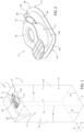
Figure 1 is a schematic perspective view of a composite package according to a first embodiment of the present invention, with parts removed for clarity; -
Figure 2 is an enlarged perspective view of an opening device of the composite package ofFigure 1 , with parts removed for clarity; -
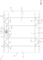
Figure 3 is a top view of a packaging material sheet for the formation of a composite package according toFigure 1 , with parts removed for clarity; -
Figure 4 is a schematic perspective view of a composite package according to a second embodiment of the present invention, with parts removed for clarity; -
Figure 5 is an enlarged perspective view of an opening device of the composite package ofFigure 4 , with parts removed for clarity; -
Figure 6 is a top view of a packaging material sheet for the formation of a composite package according toFigure 4 , with parts removed for clarity; -
Figure 7 is a schematic perspective view of a composite package according to a third embodiment that is not part of the present invention, with parts removed for clarity; -
Figure 8 is an enlarged perspective view of an opening device of the composite package ofFigure 7 , with parts removed for clarity; and -
Figure 9 is a top view of a packaging material sheet for the formation of a composite package according toFigure 7 , with parts removed for clarity. -
Number 1 indicates as a whole a first embodiment of a composite package for a pourable product, in particular a pourable food product, even more particular a liquid food product, comprising: - a (composite)
main body 2, in particular a sealed (composite)main body 2, being filled with a pourable product, in particular a pourable food product, even more particular a liquid food product, and having a designated opening configured to allow for an outflow of the pourable product frommain body 2; and - an
opening device 3, in particular aplastic opening device 3, connected tomain body 2 about the designated opening and configured to seal the designated opening, in particular prior to the first-time use ofpackage 1. - In particular,
package 1 may be obtained from a composite packaging material sheet 4, in particular having a multilayer structure, as e.g. disclosed inFigure 3 . - With particular reference to
Figure 1 ,package 1, in particularmain body 2, may extend along a longitudinal axis A, a first transversal axis B and a second transversal axis C. In particular, the extension ofpackage 2 along longitudinal axis A may be larger than the extension ofpackage 2 along first transversal axis B and second transversal axis C. - Preferentially,
package 1, in particularmain body 2, may be parallelepiped-shaped. Alternatively,package 1, in particularmain body 2, may have a cylindrical shape or any other shape. - In more detail,
main body 2 may comprise a plurality of walls, in particular afirst wall 5, one or morelateral walls 6, in the specific case shown four, and at least onesecond wall 7, in the specific case shown one. - More specifically,
first wall 5 may be transversal, in particular perpendicular, to longitudinal axis A, andmain body 2 may extend fromfirst wall 5 along longitudinal axis A. Preferentially,first wall 5 may define a support surface ofpackage 1, in particularmain body 2, which is designed to be put in contact with a support, such as e.g. a shelf, in particular when, in use, being e.g. exposed within a sales point or when being stored. In particular, when being arranged on a supportfirst wall 5 defines a bottom wall ofpackage 1. - Additionally,
first wall 5 may define a bottom wall ofpackage 1 during a normal use ofpackage 1. - Furthermore,
lateral walls 6 may be (fixedly) connected tofirst wall 5 and extend, in particular (substantially) parallel to longitudinal axis A, fromfirst wall 5. In particular, lateral walls 6 (substantially) define the extension ofpackage 1 along longitudinal axis A. - Additionally,
second wall 7 may be positioned opposite tofirst wall 5 and may be (fixedly) connected to (at least some)lateral walls 6. In particular, alsosecond wall 7 may be transversal to longitudinal axis A. - In particular,
lateral walls 6 may be interposed betweenfirst wall 5 andsecond wall 7. - In particular, when being arranged on a support and/or during a normal use of
package 1,second wall 7 may define a top wall ofmain body 2. - According to some non-limiting embodiments,
first wall 5 andsecond wall 7 may be parallel to one another. - According to alternative non-limiting embodiments not shown,
first wall portion 5 andsecond wall portion 7 may be inclined with respect to one another. - According to another alternative embodiment not shown,
second wall 7 may have two portions transversal to one another (i.e. so as to form a gable-top configuration). - According to some non-limiting embodiments,
second wall 7 may carry and/or comprise the designated opening. - Furthermore,
main body 2 may comprise a plurality of edges, in particular: - a plurality of
longitudinal edges 8, in the specific case shown four, each arranged and/or formed between two neighboringlateral walls 6; - a plurality of first
transversal edges 9, in the specific case shown four, each arranged and/or formed between one respectivelateral wall 6 andfirst wall 5; and - a plurality of second
transversal edges 10, in the specific case shown four, each arranged and/or formed between one respectivelateral wall 6 andsecond wall 7. - In particular, first
transversal edges 9 and secondtransversal edges 10 may be transversal, in particular perpendicular, tolongitudinal edges 8. - In further detail, first
transversal edges 9 may define bottom transversal edges ofmain body 2 and secondtransversal edges 10 may define top transversal edges ofmain body 2. - Moreover,
longitudinal edges 8 may be (substantially) parallel to longitudinal axis A. - Furthermore,
main body 2 may comprise aninner space 11 for the pourable product. In particular,first wall 5,lateral walls 6 andsecond wall 7 may delimitinner space 11. - Additionally, the designated opening may be configured to allow for the outpouring of the pourable product from
main body 2, in particular out ofinner space 11. - Furthermore,
package 1, in particularmain body 2, may comprise aninner surface 12 facinginner space 11 and/or contacting the pourable product, and in particular anouter surface 13 opposite toinner surface 12. - With particular reference to
Figures 1 to 3 ,opening device 3 is configured to close and seal the designated opening, in particular prior to the first-time use ofpackage 1, and to be controllable in an open configuration, in whichopening device 3 frees at least a portion of the designated opening so as to allow the outpouring of the pourable product frompackage 1, in particularmain body 2. - Additionally,
opening device 3 may also be controllable in a closing configuration, in whichopening device 3 closes the designated opening. - Moreover, prior to the first-time use of
package 1,opening device 3 is controlled in the closing configuration and is configured to seal and close the designated opening and after the first-time control ofopening device 3 in the opening configuration and when controllingopening device 3 back in the closing configuration,opening device 3 is adapted to close the designated opening. - With particular reference to
Figures 1 to 3 ,opening device 3 comprises at least abase frame 15 forcoupling opening device 3 tomain body 2. - Additionally,
base frame 15 may be arranged about the designated opening. In particular,base frame 15 may comprise a passage, in particular being aligned with at least a portion of the designated opening. - Furthermore,
opening device 3 may comprise acollar 17 extending frombase frame 15 and alid 18 coupled and/or couplable tocollar 17. - In more detail,
collar 17 may comprise an outlet opening, in particular aligned with the passage and the designated opening, being configured to allow for the outflow of the pourable product, andlid 18 is configured to selectively close and open the outlet opening. - In further detail, prior to a first-time use,
lid 18 may be in a closing position, in whichlid 18 closes and seals the outlet opening. Additionally,lid 18 may be moveable in an open position, in whichlid 18 opens the outlet opening. Moreover, oncelid 18 has been moved for the first time to the open position,lid 18 is repeatedly moveable between the open position and the closing position, but when being in theclosing position lid 18 is configured to close the outlet opening. - In particular,
opening device 3 is controlled in the open configuration and the closing configuration withlid 18 being in the open position and the closing position. - In even further detail, prior to the first-time control of
lid 18 from the closing position to the open position,lid 18 is rupturably joined to a rim ofcollar 17, the rim delimiting the outlet opening. - Additionally,
opening device 3 may comprise atethering element 19tethering lid 18 tocollar 17 and/orbase frame 15, in the specific case shown tocollar 17. - Moreover,
opening device 3 may comprise a retainingelement 20 configured to retainlid 18 in the open position. In particular, retainingelement 20 may be configured to interact withtethering element 19 so as to retainlid 18 in the open position. - In particular, retaining
element 20 is (integrally) connected to, and extends from,base frame 15. - With particular reference to
Figure 3 ,package 1 is formed from apackaging material sheet 21 comprising: - a (composite) packaging
material sheet base 22 comprising a multilayer packaging material having the designated opening; and - opening
device 3 applied on packagingmaterial sheet base 22 and about the designated opening. - It should be noted that packaging
material sheet base 22 comprises the designated opening and oncepackage 1 has been formed frompackaging material sheet 21 the designated opening ofmain body 2 originates from the designated opening of packagingmaterial sheet base 22. - It should be furthermore noted that
main body 2 is obtained by folding and sealing packagingmaterial sheet base 22 and, as openingdevice 3 is connected to packaging material sheet base 22 (as part of packaging material sheet 21),opening device 3 is also coupled tomain body 2 after formation ofpackage 1 as a whole. - Moreover, packaging
material sheet base 22 may comprise a first face and asecond face 24 opposite to the first face. In particular, the first face definesouter surface 13 andsecond face 24 definesinner surface 12 oncepackage 1 has been formed frompackaging material sheet 21. - In even further detail, packaging
material sheet base 22 may comprise at least one layer of fibrous material, such as e.g. a paper or cardboard, and at least two layers of heat-seal plastic material, e.g. polyethylene, interposing the layer of fibrous material in between one another. One of these two layers of heat-seal plastic material defining the first face and the other one definingsecond face 24. - Moreover, packaging
material sheet base 22 may also comprise a layer of gas- and light-barrier material, e.g. aluminum foil or ethylene vinyl alcohol (EVOH) film, in particular being arranged between one of the layers of the heat-seal plastic material and the layer of fibrous material. Preferentially, the packaging material may also comprise a further layer of heat-seal plastic material being interposed between the layer of gas- and light-barrier material and the layer of fibrous material. - With particular reference to
Figure 3 ,packaging material sheet 21, in particular packagingmaterial sheet base 22, comprises a plurality ofcrease lines 30 delimiting and/or defining a plurality ofpanels 31 ofpackaging material sheet 21, in particular packagingmaterial sheet base 22. - More specifically,
packaging material sheet 21, in particular packagingmaterial sheet base 22, is folded alongcrease lines 30 so as to obtainpackage 1. - In particular, at least some
crease lines 30 define and/or correspond tolongitudinal edges 8, at least somecrease lines 30 define and/or correspond to firsttransversal edges 9 and at least somecrease lines 30 define and/or correspond to second transversal edges 10. - In further detail, each
panel 31 may define at least partially a respective wall (first wall 5 or onelateral wall 6 or second wall 7) ofmain body 2. - Moreover, at least one
panel 31 may comprise the designated opening. In particular, according to the invention shown inFigure 3 , exactly onepanel 31 comprises the designated opening. - Preferentially, the
panel 31 comprising the designated opening may at least partially formsecond wall 7 after formation ofpackage 1. - In more detail, the
panel 31 having the designated opening may be sealed during the formation ofpackage 1 with anotherpanel 31 so as to formsecond wall 7. - Moreover, the
panel 31 having the designated opening may be delimited by a plurality ofcrease lines 30 and/or may have a rectangular shape. - With particular reference to
Figures 2 and3 ,base frame 15 comprises at least afirst flange 34 molded ontosecond face 24. - In more detail,
first flange 34 may have at least aperipheral portion 35, in particular having an annular shape. - In even more detail,
first flange 34, in particularperipheral portion 35, may comprise a rectilinearperipheral portion 36 being adjacent and parallel to onerespective crease line 30 defining a reference crease line 37. In particular, reference crease line 37 has a rectilinear shape, too. - Additionally,
first flange 34, in particularperipheral portion 35, may comprise an auxiliaryperipheral portion 38 spaced apart from rectilinearperipheral portion 36 and facing away from and being distanced from reference crease line 37. In the specific example shown, auxiliaryperipheral portion 38 has a rectilinear shape, in particular being (substantially) parallel to rectilinearperipheral portion 36. Alternatively, auxiliaryperipheral portion 38 may have a shape different from the rectilinear one. - Moreover,
first flange 34, in particularperipheral portion 35, may comprise further auxiliaryperipheral portions 39 connecting rectilinearperipheral portion 36 and auxiliaryperipheral portion 38 to one another. In particular, auxiliaryperipheral portions 39, rectilinearperipheral portion 36 and auxiliaryperipheral portion 38 may define an annular shape. - In further detail,
first flange 34 may comprise the passage. - Furthermore,
first flange 34 may comprise aninner portion 40 being connected toperipheral portion 35. In particular,peripheral portion 35 may be radially arranged outside andinner portion 40 may be radially arranged inside. - Moreover,
peripheral portion 35 may extend within a first plane andinner portion 40 may extend within a second plane displaced from the first plane. In particular,inner portion 40, even more particular the second plane, may be flush with the first face. - Moreover, first plane may be flush with
second face 24. - Moreover,
collar 17 is integral tofirst flange 34 and extends fromfirst flange 34. - According to the invention a distance between rectilinear
peripheral portion 34 and reference crease line 37 may be equal or less than 2,0 mm, in particular equal or less than 1,0 mm, even more particular equal or less than 0,9 mm. In particular, the distance between rectilinearperipheral portion 34 and reference crease line 37 is determined with respect to a direction normal to crease line 37 and rectilinearperipheral portion 34. - According to some possible embodiments, rectilinear
peripheral portion 36 may be in contact with reference crease line 37. In particular, rectilinearperipheral portion 36 may abut against reference crease line 37 or may extend into reference crease line 37 (i.e. rectilinearperipheral portion 36 may superimpose a portion of reference crease line 37). - Once
package 1 has been formed formpackaging material sheet 21,first flange 34 may be connected, in particular fused, to inner surface 12 (i.e.first flange 34 is arranged within inner space 11). Additionally, rectilinearperipheral portion 36 may be adjacent and parallel to reference crease line 37. In particular, reference crease line 37 corresponds and/or defines one respective secondtransversal edge 10. - Moreover, rectilinear
peripheral portion 36 may be adjacent to one respectivelateral wall 6. In particular a distance between rectilinearperipheral portion 36 and the respectivelateral wall 6 may be equal or less than 2,0 mm, in particular equal or less than 1,0 mm, even more particular equal or less than 0,9 mm. - According to some possible embodiments, rectilinear
peripheral portion 36 may abut against the respectivelateral wall 6. - With particular reference to
Figure 2 , retainingelement 20 is (integrally) connected to and extends fromfirst flange 15, in particularperipheral portion 35. - According to the specific embodiment of
Figures 1 to 3 ,peripheral portion 35 may be arranged withininner space 11. - Furthermore, the forming of one respective
packaging material sheet 21 comprises at least the steps of: - providing the respective packaging
material sheet base 22 having the designated opening; - arranging a mold around the designated opening; and
- feeding a molten polymer to the mold and molding the
respective opening device 3 onto packagingmaterial sheet base 21 and about the designated opening. - In particular, the mold has a cavity corresponding to the shape of
opening device 3. - According to some possible embodiments, in particular for improving the preciseness of the positioning of
opening device 3, the formation ofpackaging material sheet 21 also comprises the step of: - reading a mark applied on packaging
material sheet base 22; and - aligning the mold around the designated opening in dependence of the position of the mark.
- In particular, the mark may be a magnetic mark or a different kind of mark. Preferentially, the mark may be a magnetic mark as allowing for a precise positioning of the mold and therewith of
opening device 3. - In further detail, packaging material sheet bases 22 may be provided in the form of a web. In particular, the web comprises a plurality of basic units, each basic unit corresponding to one respective packaging
material sheet base 22. Thus, during the step of providing, the web of packaging material sheet bases 22 is advanced, in particular intermittently advanced, to a molding station, at which openingdevices 3 are molded onto the respective packaging material sheet bases 22. In this way, one obtains a web ofpackaging material sheets 21. - Moreover, the formation of
packages 1 comprises the following steps: - providing
packaging material sheet 21; - folding
packaging material sheet 21 according tocrease lines 30 for obtainingpackage 1; - sealing, in particular longitudinally and transversally sealing,
package 1; and - filling
package 1 with the pourable product. - In more detail,
packaging material sheet 21 may be provided in the form of a web ofpackaging material sheets 21 and the web ofpackaging material sheets 21 may be (continuously) advanced to a tube forming station, at which the web ofpackaging material sheets 21 may be formed into a tube. - Moreover, during the step of sealing, the tube may be longitudinally sealed and transversally sealed.
- Additionally, during the step of filling, the tube may be filled with the pourable product.
- The formation of
packages 1 may also comprise the step of forming, during which the tube is formed and the step of transversally cutting the tube so as to obtain the single packages 1. - With reference to
Figure 4 , number 1' indicates an alternative embodiment of a package according to the present invention; as package 1' is similar topackage 1, the following description is limited to the differences between them, and using the same references, where possible, for identical or corresponding parts. - In particular, package 1' differs from
package 1 in comprising opening device 3'. - As well, package 1' differs from
package 1 in being formed from a packaging material sheet 21' (seeFigure 6 ). - As packaging material sheet 21' is similar to
packaging material sheet 21, the following description is limited to the differences between them, and using the same references, where possible, for identical or corresponding parts. - In particular, also packaging material sheet 21' differs from
packaging material sheet 21 in comprising opening device 3'. - In more detail and with particular reference to
Figures 4 and 5 , opening device 3' differs from openingdevice 3 in thatbase frame 15 further comprises asecond flange 40 spaced apart from, and in particular being parallel to,first flange 34. - Preferentially,
first flange 34 andsecond flange 40 may be connected to one another. - In particular,
second flange 40 is molded onto the first face or after formation ofpackage 1 ontoouter surface 13. - Furthermore,
first flange 34 andsecond flange 40 define a respective interspace interposing between one another a portion of packagingmaterial sheet base 22 or after formation ofpackage 1 ofsecond wall 7. - In further detail and with particular reference to
Figures 4 and 5 ,second flange 40 may comprise aperipheral portion 42, in particular having the same shape asperipheral portion 35. Alternatively,peripheral portion 42 may have a shape at least partially differentiating from the shape ofperipheral portion 35. - As the formation of packaging material sheets 21' is similar to the formation of
packaging material sheets 21, we refer to the description as provided with respect to the formation ofpackaging material sheets 21. - Additionally, as the formation of package 1' is similar to the formation of
package 1, we refer to the description as provided with respect to the formation ofpackage 1. - With reference to
Figure 7 , number 1'' indicates an alternative embodiment of a package that is not part of the present invention; as package 1'' is similar topackage 1, the following description is limited to the differences between them, and using the same references, where possible, for identical or corresponding parts. - In particular, package 1'' differs from
package 1 in comprising opening device 3'' and in that the designated opening extends over two respective walls, in particularsecond wall 7 and onelateral wall 6. - As well, package 1'' differs from package 1' in being formed from a packaging material sheet 21'' (see
Figure 9 ). - As packaging material sheet 21'' is similar to packaging material sheet 21', the following description is limited to the differences between them, and using the same references, where possible, for identical or corresponding parts.
- In particular, packaging material sheet 21'' differs from packaging material sheet 21' in comprising opening device 3'' and packaging
material sheet base 22". - In more detail, packaging
material sheet base 22" differs from packagingmaterial sheet base 22 in that the designated opening comprises a first opening portion and a second opening portion. - Furthermore, one
panel 31, in particular the one at least partially definingsecond wall 7, comprises the first opening portion and anotherpanel 31, in particular the one defining onelateral wall 6, comprises the second opening portion. - In more detail, one
crease line 30, in particular being transversal, even more particular perpendicular, to reference crease line 37, is interposed between thepanel 31 having the first opening portion and thepanel 31 having the second opening portion. - In even more detail, the
crease line 30 being interposed between thepanel 31 having the first opening portion and thepanel 31 having the second opening portion defines an auxiliary reference crease line 46 being transversal, in particular perpendicular, to reference crease line 37.
In addition, and with particular reference toFigures 7 to 9 , opening device 3'' differs from opening device 3'in thatfirst flange 34 may comprise afirst flange portion 47, asecond flange portion 48 and afold line 49 interposed betweenfirst flange portion 47 andsecond flange portion 48. In particular, foldline 49 is configured such that during formation ofpackage 1, i.e. during the folding of the respective packaging material sheet 21'',first flange 34 is folded alongfold line 49 such thatfirst flange portion 47 andsecond flange portion 48 are arranged transversal, in particular (substantially) perpendicularly to one another. - Preferentially, fold
line 49 may be parallel to auxiliary reference crease line 46. In particular, foldline 49 may be aligned with auxiliary reference crease line 46. - According to some possible non-limiting embodiments, a distance between auxiliary reference crease line 46 and fold
line 49 may be equal or less than 2,0 mm, in particular equal or less than 1,0 mm, even more particular equal or less than 0,5 mm. - Moreover,
first flange portion 47 may be associated to the first opening portion andsecond flange portion 48 may cover and seal the second opening portion. - Additionally, auxiliary reference crease line 46 may comprise a
first section 50 and a second section 51 detached from one another. - Advantageously, fold
line 49 may be parallel to and interposed betweenfirst section 50 and second section 51. In particular, foldline 49 may extend betweenfirst section 50 and second section 51. - Furthermore,
first flange portion 47 may compriseperipheral portion 35, in particular rectilinearperipheral portion 36. - Moreover,
first flange portion 47 may comprise the passage andcollar 17 may be connected to and extend fromfirst flange portion 47. As well, retainingelement 20 may extend fromfirst flange portion 47. - It is to be noted that once package 1'' has been formed from packaging material sheet 21'', one respective wall of
main body 2 comprises the first opening portion and another wall the second opening portion, in particular the two walls being transversal to one another. In more detail,second wall 7 comprises the first opening portion and onetransversal wall 6 the second opening portion. - As the formation of packaging material sheets 21'' is similar to the formation of
packaging material sheets 21, we refer to the description as provided with respect to the formation ofpackaging material sheets 21. - Additionally, as the formation of
package 1" is similar to the formation ofpackage 1, we refer to the description as provided with respect to the formation ofpackage 1. - The advantages of
packaging material sheet 21, 21' and/or ofpackage 1, 1' and/or the method for forming apackaging material sheet 21, 21' and/or the method for forming apackage 1, 1' according to the present invention will be clear from the foregoing description. - In particular, by relying on
packaging material sheets 21, 21' for the formation ofpackages 1, 1', it is possible to improve the transportation and reclosing properties ofpackages 1, 1'. In particular, by having rectilinearperipheral portion 35 being adjacent and parallel to reference crease line 37 (the respective second transversal edge 10) it is possible to transfer a load acting on therespective opening device 3, 3' onto one or morelateral walls 6. This again allows to avoid any risk of possible deformations of the respectivemain body 2. - A further advantage resides in providing for a
first flange 34 having afirst flange portion 47 and asecond flange portion 48 further enhancing the effects of rectilinearperipheral portion 35 being adjacent and parallel to reference crease line 37 (the respective second transversal edge 10). - An additional advantage resides in that having rectilinear
peripheral portion 35 being adjacent and parallel to reference crease line 37 improves the folding ofpackaging material sheets 21, 21', into therespective packages 1, 1'. - Clearly, changes may be made to
packaging material sheet 21, 21' and/orpackage 1, 1' and/or the method for forming apackaging material sheet 21, 21' and/or the method for forming apackage 1, 1' as described herein without, however, departing from the scope of protection as defined in the accompanying claims. - According to some possible embodiments not shown, opening device 3'' may not comprise a
second flange 41.
Claims (9)
- Composite packaging material sheet (21, 21') for the formation of a composite package (1, 1') filled with a pourable product comprising at least:- a packaging material sheet base (22) comprising a multilayer packaging material having a designated opening; and- an opening device (3, 3') applied on the packaging material sheet base (22) and about the designated opening and designed to seal the designated opening and being controllable in an open position so as to free at least a portion of the designated opening;wherein the packaging material sheet base (22) comprises at least a first face and a second face (24) opposite to the first face;wherein the second face (24) is designed to define an inner surface (12) of the composite package (1, 1') to be formed from the composite packaging material sheet (21, 21');wherein the packaging material sheet base (22) comprises a plurality of crease lines (30) delimiting a plurality of panels (31);wherein the opening device (3, 3') comprises a base frame (15) for coupling the opening device (3, 3') to the packaging material sheet base (22) and about the designated opening;wherein the base frame (15) comprises at least a first flange (34) connected to the second face (24) and having a rectilinear peripheral portion (36);wherein the rectilinear peripheral portion (36) is parallel to one respective crease line (30) defining a reference crease line (37);wherein the first flange (34) is molded onto the second face (24);characterized in thatexactly one panel (31) comprises the designated opening; and in thatthe rectilinear peripheral portion (36) is adjacent to said one respective crease line (30) defining said reference crease line (37) and a distance between the rectilinear peripheral portion (36) and the reference crease line (37) is equal or less than 2,0 mm.
- Composite packaging material sheet according to claim 1,
wherein the rectilinear peripheral portion (36) is in contact with the reference crease line (37). - Composite packaging material sheet according to claim 2,
wherein the rectilinear peripheral portion (36) abuts against the reference crease line (37). - Composite packaging material sheet according to claim 2,
wherein the rectilinear peripheral portion (36) extends into the reference crease line (37). - Method for forming a composite packaging material sheet (21, 21') according to any one of the preceding claims, comprising at least the steps of:- providing a packaging material sheet base (22) having a designated opening;- arranging a mold around the designated opening; and- feeding a molten polymer to the mold and molding the opening device (3, 3') onto the packaging material sheet base (22) and about the designated opening.
- Method according to claim 5, and further comprising the step of:- reading a mark applied on the packaging material sheet base (22); and- aligning the mold around the designated opening in dependence of the position of the mark.
- Composite package formed from a composite packaging material sheet (21, 21') according to any one of claims 1 to 4.
- Composite package according to claim 7, wherein the reference crease line (37) is interposed between a first wall (7) of the package (1, 1'), and a second wall (6) of the package (1, 1') being transversal to one another.
- Method for forming a composite package according to claim 7 or 8, comprising at least the steps of:- providing a composite packaging material sheet (21, 21') according to any one of claims 1 to 4;- folding the composite packaging material sheet according to the crease lines for obtaining the composite package (1, 1');- sealing the composite package (1, 1'); and- filling the composite package (1, 1') with the pourable product.
Applications Claiming Priority (1)
| Application Number | Priority Date | Filing Date | Title |
|---|---|---|---|
| EP21174384 | 2021-05-18 |
Publications (3)
| Publication Number | Publication Date |
|---|---|
| EP4091953A1 EP4091953A1 (en) | 2022-11-23 |
| EP4091953B1 true EP4091953B1 (en) | 2025-07-02 |
| EP4091953C0 EP4091953C0 (en) | 2025-07-02 |
Family
ID=75977672
Family Applications (1)
| Application Number | Title | Priority Date | Filing Date |
|---|---|---|---|
| EP22172889.2A Active EP4091953B1 (en) | 2021-05-18 | 2022-05-12 | Composite packaging material sheet, method for forming a composite packaging material sheet, composite package and method for forming a composite package |
Country Status (8)
| Country | Link |
|---|---|
| US (1) | US20240158128A1 (en) |
| EP (1) | EP4091953B1 (en) |
| JP (1) | JP2024517374A (en) |
| CN (1) | CN117083227A (en) |
| BR (1) | BR112023018769A2 (en) |
| ES (1) | ES3037332T3 (en) |
| MX (1) | MX2023010886A (en) |
| WO (1) | WO2022243143A1 (en) |
Families Citing this family (2)
| Publication number | Priority date | Publication date | Assignee | Title |
|---|---|---|---|---|
| JP1759380S (en) * | 2021-05-18 | 2023-12-12 | packaging box with lid | |
| USD1069578S1 (en) * | 2022-08-08 | 2025-04-08 | Tetra Laval Holdings & Finance S.A. | Lid for containers |
Family Cites Families (14)
| Publication number | Priority date | Publication date | Assignee | Title |
|---|---|---|---|---|
| JPH0340765Y2 (en) * | 1985-05-27 | 1991-08-27 | ||
| JPH0235606Y2 (en) * | 1986-01-21 | 1990-09-27 | ||
| JPH0745143B2 (en) * | 1986-03-12 | 1995-05-17 | 大日本印刷株式会社 | Molding method of spout for liquid packaging container |
| JPH0551032A (en) * | 1991-08-15 | 1993-03-02 | Dainippon Printing Co Ltd | Paper container |
| JPH0789535A (en) * | 1993-06-30 | 1995-04-04 | Dainippon Printing Co Ltd | Brick paper container |
| DE60014332T2 (en) * | 2000-05-30 | 2005-12-01 | Tetra Laval Holdings & Finance S.A. | Opening device for a package for flowable food and this comprehensive packaging |
| SE521912C2 (en) * | 2000-11-28 | 2003-12-16 | Tetra Laval Holdings & Finance | Method for arranging opening devices directly on a packaging material web for pourable products and a package obtained thereby. |
| PT2008787E (en) * | 2007-06-28 | 2012-05-17 | Tetra Laval Holdings & Finance | Method of injection molding opening devices on sheet material for packaging pourable food products, and packaging material and package obtained thereby |
| EP2392517A1 (en) * | 2010-06-07 | 2011-12-07 | Tetra Laval Holdings & Finance S.A. | Sealed package for pourable food products and packaging material for producing sealed packages for pourable food products |
| CN112173427B (en) * | 2012-10-26 | 2023-01-03 | 优装有限责任公司 | Flexible package and method of making same |
| EP2944458B1 (en) * | 2014-05-16 | 2020-04-29 | Tetra Laval Holdings & Finance S.A. | Sheet of packaging material for producing a container and method for producing containers |
| RU2018145521A (en) * | 2016-05-25 | 2020-06-25 | Тетра Лаваль Холдингз Энд Файнэнс С.А. | PACKING MATERIAL AND PACKING |
| US12037167B2 (en) * | 2018-04-20 | 2024-07-16 | Tetra Laval Holdings & Finance S.A. | Sheet packaging material for producing a sealed package containing a pourable food product and a sealed package obtained from a sheet packaging material |
| BR112022019175A2 (en) * | 2020-05-27 | 2022-12-06 | Tetra Laval Holdings & Finance | NOZZLE SET WITH COVER, AND, PACKAGING |
-
2022
- 2022-05-12 ES ES22172889T patent/ES3037332T3/en active Active
- 2022-05-12 WO PCT/EP2022/062875 patent/WO2022243143A1/en not_active Ceased
- 2022-05-12 BR BR112023018769A patent/BR112023018769A2/en unknown
- 2022-05-12 US US18/550,340 patent/US20240158128A1/en active Pending
- 2022-05-12 CN CN202280023222.8A patent/CN117083227A/en active Pending
- 2022-05-12 EP EP22172889.2A patent/EP4091953B1/en active Active
- 2022-05-12 MX MX2023010886A patent/MX2023010886A/en unknown
- 2022-05-12 JP JP2023558145A patent/JP2024517374A/en active Pending
Also Published As
| Publication number | Publication date |
|---|---|
| US20240158128A1 (en) | 2024-05-16 |
| MX2023010886A (en) | 2023-09-27 |
| BR112023018769A2 (en) | 2023-12-05 |
| JP2024517374A (en) | 2024-04-22 |
| EP4091953A1 (en) | 2022-11-23 |
| CN117083227A (en) | 2023-11-17 |
| EP4091953C0 (en) | 2025-07-02 |
| WO2022243143A1 (en) | 2022-11-24 |
| ES3037332T3 (en) | 2025-10-01 |
Similar Documents
| Publication | Publication Date | Title |
|---|---|---|
| EP4159631B1 (en) | Opening device for a package, mold for molding an opening device for a package and package having an opening device | |
| EP4091953A1 (en) | Composite packaging material sheet, method for forming a composite packaging material sheet, composite package and method for forming a composite package | |
| EP4159402B1 (en) | Opening device for a package, mold for molding an opening device for a package and package having an opening device | |
| EP4159634B1 (en) | Opening device for a package, mold for molding an opening device for a package and package having an opening device | |
| EP4177181B1 (en) | Opening device for a package and package having an opening device | |
| EP4159633A1 (en) | Opening device for a package, mold for molding an opening device for a package and package having an opening device | |
| EP4119457B1 (en) | Package for holding a food product and mould for a packaging machine | |
| EP4091954A1 (en) | Spout assembly, composite packaging material sheet, method for forming a composite packaging material sheet, composite package and method for forming a composite package | |
| EP4124584A1 (en) | Opening device for a package and package having an opening device | |
| US20250153892A1 (en) | Lid assembly for a package, lid-spout group for a package and package having a lid-spout group | |
| EP4079652B1 (en) | Opening device for a package and package having an opening device | |
| EP4159632A1 (en) | Opening device for a package, mold for molding an opening device for a package and package having an opening device | |
| EP4606727A1 (en) | Closure for an opening device, opening device for a package and package | |
| EP4606728A1 (en) | Closure for an opening device, opening device for a package and package | |
| EP4001149A1 (en) | Opening device for a package and package having an opening device | |
| AU2024310800A1 (en) | Opening device for a package and package having an opening device | |
| WO2026008333A1 (en) | Opening device for a package and package having an opening device | |
| WO2024260877A1 (en) | Opening device for a package, mold for molding an opening device and package having an opening device |
Legal Events
| Date | Code | Title | Description |
|---|---|---|---|
| PUAI | Public reference made under article 153(3) epc to a published international application that has entered the european phase |
Free format text: ORIGINAL CODE: 0009012 |
|
| STAA | Information on the status of an ep patent application or granted ep patent |
Free format text: STATUS: THE APPLICATION HAS BEEN PUBLISHED |
|
| AK | Designated contracting states |
Kind code of ref document: A1 Designated state(s): AL AT BE BG CH CY CZ DE DK EE ES FI FR GB GR HR HU IE IS IT LI LT LU LV MC MK MT NL NO PL PT RO RS SE SI SK SM TR |
|
| STAA | Information on the status of an ep patent application or granted ep patent |
Free format text: STATUS: REQUEST FOR EXAMINATION WAS MADE |
|
| 17P | Request for examination filed |
Effective date: 20230523 |
|
| RBV | Designated contracting states (corrected) |
Designated state(s): AL AT BE BG CH CY CZ DE DK EE ES FI FR GB GR HR HU IE IS IT LI LT LU LV MC MK MT NL NO PL PT RO RS SE SI SK SM TR |
|
| STAA | Information on the status of an ep patent application or granted ep patent |
Free format text: STATUS: EXAMINATION IS IN PROGRESS |
|
| 17Q | First examination report despatched |
Effective date: 20240801 |
|
| GRAP | Despatch of communication of intention to grant a patent |
Free format text: ORIGINAL CODE: EPIDOSNIGR1 |
|
| STAA | Information on the status of an ep patent application or granted ep patent |
Free format text: STATUS: GRANT OF PATENT IS INTENDED |
|
| INTG | Intention to grant announced |
Effective date: 20250124 |
|
| GRAS | Grant fee paid |
Free format text: ORIGINAL CODE: EPIDOSNIGR3 |
|
| GRAA | (expected) grant |
Free format text: ORIGINAL CODE: 0009210 |
|
| STAA | Information on the status of an ep patent application or granted ep patent |
Free format text: STATUS: THE PATENT HAS BEEN GRANTED |
|
| AK | Designated contracting states |
Kind code of ref document: B1 Designated state(s): AL AT BE BG CH CY CZ DE DK EE ES FI FR GB GR HR HU IE IS IT LI LT LU LV MC MK MT NL NO PL PT RO RS SE SI SK SM TR |
|
| REG | Reference to a national code |
Ref country code: GB Ref legal event code: FG4D |
|
| REG | Reference to a national code |
Ref country code: CH Ref legal event code: EP |
|
| REG | Reference to a national code |
Ref country code: DE Ref legal event code: R096 Ref document number: 602022016707 Country of ref document: DE |
|
| REG | Reference to a national code |
Ref country code: IE Ref legal event code: FG4D |
|
| U01 | Request for unitary effect filed |
Effective date: 20250703 |
|
| U07 | Unitary effect registered |
Designated state(s): AT BE BG DE DK EE FI FR IT LT LU LV MT NL PT RO SE SI Effective date: 20250710 |
|
| REG | Reference to a national code |
Ref country code: ES Ref legal event code: FG2A Ref document number: 3037332 Country of ref document: ES Kind code of ref document: T3 Effective date: 20251001 |
|
| PG25 | Lapsed in a contracting state [announced via postgrant information from national office to epo] |
Ref country code: IS Free format text: LAPSE BECAUSE OF FAILURE TO SUBMIT A TRANSLATION OF THE DESCRIPTION OR TO PAY THE FEE WITHIN THE PRESCRIBED TIME-LIMIT Effective date: 20251102 |
|
| PG25 | Lapsed in a contracting state [announced via postgrant information from national office to epo] |
Ref country code: NO Free format text: LAPSE BECAUSE OF FAILURE TO SUBMIT A TRANSLATION OF THE DESCRIPTION OR TO PAY THE FEE WITHIN THE PRESCRIBED TIME-LIMIT Effective date: 20251002 |
|
| PG25 | Lapsed in a contracting state [announced via postgrant information from national office to epo] |
Ref country code: HR Free format text: LAPSE BECAUSE OF FAILURE TO SUBMIT A TRANSLATION OF THE DESCRIPTION OR TO PAY THE FEE WITHIN THE PRESCRIBED TIME-LIMIT Effective date: 20250702 |
|
| PG25 | Lapsed in a contracting state [announced via postgrant information from national office to epo] |
Ref country code: GR Free format text: LAPSE BECAUSE OF FAILURE TO SUBMIT A TRANSLATION OF THE DESCRIPTION OR TO PAY THE FEE WITHIN THE PRESCRIBED TIME-LIMIT Effective date: 20251003 |
|
| PG25 | Lapsed in a contracting state [announced via postgrant information from national office to epo] |
Ref country code: CZ Free format text: LAPSE BECAUSE OF FAILURE TO SUBMIT A TRANSLATION OF THE DESCRIPTION OR TO PAY THE FEE WITHIN THE PRESCRIBED TIME-LIMIT Effective date: 20250702 |
|
| PG25 | Lapsed in a contracting state [announced via postgrant information from national office to epo] |
Ref country code: PL Free format text: LAPSE BECAUSE OF FAILURE TO SUBMIT A TRANSLATION OF THE DESCRIPTION OR TO PAY THE FEE WITHIN THE PRESCRIBED TIME-LIMIT Effective date: 20250702 |
|
| PG25 | Lapsed in a contracting state [announced via postgrant information from national office to epo] |
Ref country code: RS Free format text: LAPSE BECAUSE OF FAILURE TO SUBMIT A TRANSLATION OF THE DESCRIPTION OR TO PAY THE FEE WITHIN THE PRESCRIBED TIME-LIMIT Effective date: 20251002 |
|
| PG25 | Lapsed in a contracting state [announced via postgrant information from national office to epo] |
Ref country code: SM Free format text: LAPSE BECAUSE OF FAILURE TO SUBMIT A TRANSLATION OF THE DESCRIPTION OR TO PAY THE FEE WITHIN THE PRESCRIBED TIME-LIMIT Effective date: 20250702 |
|
| PG25 | Lapsed in a contracting state [announced via postgrant information from national office to epo] |
Ref country code: SK Free format text: LAPSE BECAUSE OF FAILURE TO SUBMIT A TRANSLATION OF THE DESCRIPTION OR TO PAY THE FEE WITHIN THE PRESCRIBED TIME-LIMIT Effective date: 20250702 |
|
| PLBE | No opposition filed within time limit |
Free format text: ORIGINAL CODE: 0009261 |
|
| STAA | Information on the status of an ep patent application or granted ep patent |
Free format text: STATUS: NO OPPOSITION FILED WITHIN TIME LIMIT |