EP4091880A1 - A cab-over engine truck - Google Patents
A cab-over engine truck Download PDFInfo
- Publication number
- EP4091880A1 EP4091880A1 EP22173836.2A EP22173836A EP4091880A1 EP 4091880 A1 EP4091880 A1 EP 4091880A1 EP 22173836 A EP22173836 A EP 22173836A EP 4091880 A1 EP4091880 A1 EP 4091880A1
- Authority
- EP
- European Patent Office
- Prior art keywords
- headlight
- adjustment mechanism
- cab
- chassis
- cabin
- Prior art date
- Legal status (The legal status is an assumption and is not a legal conclusion. Google has not performed a legal analysis and makes no representation as to the accuracy of the status listed.)
- Granted
Links
Images

Classifications
-
- B—PERFORMING OPERATIONS; TRANSPORTING
- B60—VEHICLES IN GENERAL
- B60Q—ARRANGEMENT OF SIGNALLING OR LIGHTING DEVICES, THE MOUNTING OR SUPPORTING THEREOF OR CIRCUITS THEREFOR, FOR VEHICLES IN GENERAL
- B60Q1/00—Arrangement of optical signalling or lighting devices, the mounting or supporting thereof or circuits therefor
- B60Q1/02—Arrangement of optical signalling or lighting devices, the mounting or supporting thereof or circuits therefor the devices being primarily intended to illuminate the way ahead or to illuminate other areas of way or environments
- B60Q1/04—Arrangement of optical signalling or lighting devices, the mounting or supporting thereof or circuits therefor the devices being primarily intended to illuminate the way ahead or to illuminate other areas of way or environments the devices being headlights
- B60Q1/06—Arrangement of optical signalling or lighting devices, the mounting or supporting thereof or circuits therefor the devices being primarily intended to illuminate the way ahead or to illuminate other areas of way or environments the devices being headlights adjustable, e.g. remotely-controlled from inside vehicle
- B60Q1/068—Arrangement of optical signalling or lighting devices, the mounting or supporting thereof or circuits therefor the devices being primarily intended to illuminate the way ahead or to illuminate other areas of way or environments the devices being headlights adjustable, e.g. remotely-controlled from inside vehicle by mechanical means
-
- B—PERFORMING OPERATIONS; TRANSPORTING
- B60—VEHICLES IN GENERAL
- B60Q—ARRANGEMENT OF SIGNALLING OR LIGHTING DEVICES, THE MOUNTING OR SUPPORTING THEREOF OR CIRCUITS THEREFOR, FOR VEHICLES IN GENERAL
- B60Q1/00—Arrangement of optical signalling or lighting devices, the mounting or supporting thereof or circuits therefor
- B60Q1/0005—Devices preventing the lights from becoming dirty or damaged, e.g. protection grids or cleaning by air flow
-
- B—PERFORMING OPERATIONS; TRANSPORTING
- B60—VEHICLES IN GENERAL
- B60Q—ARRANGEMENT OF SIGNALLING OR LIGHTING DEVICES, THE MOUNTING OR SUPPORTING THEREOF OR CIRCUITS THEREFOR, FOR VEHICLES IN GENERAL
- B60Q1/00—Arrangement of optical signalling or lighting devices, the mounting or supporting thereof or circuits therefor
- B60Q1/0064—Arrangement of optical signalling or lighting devices, the mounting or supporting thereof or circuits therefor with provision for maintenance, e.g. changing the light bulb
-
- B—PERFORMING OPERATIONS; TRANSPORTING
- B62—LAND VEHICLES FOR TRAVELLING OTHERWISE THAN ON RAILS
- B62D—MOTOR VEHICLES; TRAILERS
- B62D33/00—Superstructures for load-carrying vehicles
- B62D33/06—Drivers' cabs
- B62D33/063—Drivers' cabs movable from one position into at least one other position, e.g. tiltable, pivotable about a vertical axis, displaceable from one side of the vehicle to the other
- B62D33/067—Drivers' cabs movable from one position into at least one other position, e.g. tiltable, pivotable about a vertical axis, displaceable from one side of the vehicle to the other tiltable
Definitions
- the invention relates to a cab-over engine truck having a front side, a chassis, an engine compartment and a driver cabin at least partially positioned over the engine compartment, the driver cabin including an cabin part that is tiltable with regard to the chassis to allow access to the engine compartment by being hinged about a horizontal axis arranged at the front side, the chassis comprising a chassis part that remains associated with the chassis when the cabin part is tilted, the chassis part and/or cabin part having a front section carrying a headlight unit for producing a high beam and/or a low beam, the headlight unit comprising a vertical positioning adjustment member for adjusting the vertical position of the high beam and/or a low beam and a horizontal positioning adjustment member for adjusting the horizontal position of the high beam and/or a low beam.
- Such a motor vehicle is for example known from EP3421335A1 .
- the legislations e.g. the low beam of a cab-over engine truck needs to be aimed to the road in a downwards inclination angle within a certain legal boundaries which usually will be controlled and adjusted by the approval agencies yearly during vehicle technical controls or during delivery of the cab-over engine truck by the dealers to the customers.
- the service caps are provided behind the headlight unit and can be opened for accessing the horizontal and vertical positioning adjustment members of the headlight unit.
- adjustment of the vertical and/or horizontal position of the high beam and/or a low beam in this manner is laborious since reaching the horizontal and vertical positioning adjustment members of the headlight unit can be difficult for an operator.
- this object is obtained by providing a cab-over engine truck having a front side, a chassis, an engine compartment and a driver cabin at least partially positioned over the engine compartment, the driver cabin including an cabin part that is tiltable with regard to the chassis to allow access to the engine compartment by being hinged about a horizontal axis arranged at the front side, the chassis comprising a chassis part that remains associated with the chassis when the cabin part is tilted, the chassis part and/or cabin part having a front section carrying a headlight unit for producing a high beam and/or a low beam, the headlight unit comprising a vertical positioning adjustment member for adjusting the vertical position of the high beam and/or a low beam and a horizontal positioning adjustment member for adjusting the horizontal position of the high beam and/or a low beam, characterized in that the cab-over engine truck comprises an adjustment mechanism having first ends engaging the vertical positioning adjustment member and the horizontal positioning adjustment member and second ends for being operated by an operator, and in that the front side of the chassis part and/or cabin part comprises an adjustment
- the second ends of the adjustment mechanism can be easily accessed by an operator thereby making the operation of adjusting the horizontal and/or vertical position of the high beam and/or a low beam more easy.
- the adjustment mechanism access opening is positioned adjacent the headlight unit.
- the adjustment mechanism access opening is integrally arranged in the headlight unit. It is then preferred, when the adjustment mechanism access opening is covered with a removable cover to protect the second ends of the adjustment mechanism from environmental influences, in particular during driving of the cab-over engine truck.
- the front section of the chassis part and/or cabin part comprises a headlight washer unit for washing a front of the headlight unit, the headlight washer unit being positioned adjacent the headlight unit and having a headlight washer and a headlight washer cap, the headlight washer cap being configured to be positioned in either an inoperative position flush with the front of the headlight unit and covering the headlight washer or an operative position in which the headlight washer cap exposes the headlight washer, the headlight washer being configured to be positioned in either an inoperative position covered by the headlight washer cap when in inoperative position or an operative position in which the headlight washer extends in a forwards direction beyond the headlight washer cap in its operative position, the adjustment mechanism access opening being arranged behind the headlight washer cap.
- the space behind the headlight washer cap also functions as adjustment mechanism access opening and thus no separate adjustment mechanism access opening needs to be provided in the chassis part and/or cabin part. It is then preferred when the headlight washer cap is configured for being positioned in the operative position independent of the operational state of the headlight washer, in other words the headlight washer is configured for being deactivated when positioned in its operative position.
- the adjustment mechanism comprises flexible cables extending from the second ends of the adjustment mechanism to the first ends of the adjustment mechanism.
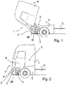
- FIGS 1 and 2 an embodiment of a cab-over engine truck 1 is schematically shown in side view.
- the cab-over engine truck 1 has a front side F, a chassis C, an engine compartment 2 and a driver cabin 3 which is at least partially positioned over the engine compartment 2.
- the driver cabin 3 comprises an cabin part 4 that is tiltable with regard to the chassis C to allow access to the engine compartment 2 by being hinged about a horizontal axis H arranged at the front side F.
- the chassis C has a chassis part 5 that remains associated with the chassis C when the cabin part 4 is tilted.
- Figure 1 the situation is shown in which the cabin part 4 of the driver cabin 3 is tilted to allow access to the engine compartment 2, while in Figure 2 the cabin part 4 is shown in closed position.
- the driver cabin 3 is further provided with a door 6 for accessing the driver cabin 3 and a number of steps 7 leading to the door 6 of the driver cabin 3.
- the chassis part 5 has a front section 5F carrying a headlight unit 8 for producing a high beam and/or a low beam and in the shown embodiment a fog light 9.
- the headlight unit 8 comprises a vertical positioning adjustment member 9 for adjusting the vertical position of the high beam and/or a low beam and a horizontal positioning adjustment member 10 for adjusting the horizontal position of the high beam and/or a low beam.
- the invention is also applicable to embodiments in which the headlight unit is arranged in the cabin part.
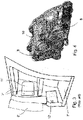
- FIG 3 a part of a prior art cab-over engine truck known from EP3421335A1 is schematically shown, which comprises service caps 11', 12' provided in side walls of the step region, which service caps can be opened for accessing adjustment members of a headlight unit in the cab-over engine truck known from EP3421335A1 service caps are provided in side walls of the step region comprising steps 7' positioned below the door 6'.
- the service caps 11', 12' are provided behind the headlight unit and the fog light, respectively and can be opened to provide an adjustment mechanism access opening for accessing the horizontal and vertical positioning adjustment members of the headlight unit and for accessing the fog light.
- the adjustment mechanism access opening 13 is positioned adjacent the headlight unit 8 at the front side 5F of the chassis part 5.
- the front section 5F of the chassis part 5 comprises a headlight washer unit 14 for washing a front of the headlight unit 8.
- the headlight washer unit 14 is positioned adjacent the headlight unit 8 and comprises a headlight washer cap 15 behind which a headlight washer 16 is arranged.
- the headlight washer cap 15 is configured to be positioned in either an inoperative position flush with the front of the headlight unit 8 (indicated in Figures 6 and 8 ) and covering the headlight washer 16 or an operative position in which the headlight washer cap 15 exposes the headlight washer 16 (as indicated in Figure 5 and 7 ).
- the headlight washer 16 is configured to be positioned in either an inoperative position covered by the headlight washer cap 15 when in inoperative position or an operative position in which the headlight washer 16 extends in a forwards direction beyond the headlight washer cap 15 in its operative position.
- the adjustment mechanism access opening 13 is positioned adjacent the headlight unit 8 behind the headlight washer cap 15.
- the adjustment mechanism access opening can be integrally arranged in the headlight unit or can be provided at another position at the front side of the chassis part.
- adjustment mechanism access opening 13 is preferably covered with a removable cover.
- the headlight washer cap 15 is configured for being positioned in the operative position independent of the operational state of the headlight washer 16, in other words the headlight washer 16 is configured for being deactivated when positioned in its operative position to allow undisturbed access to the adjustment mechanism access opening 13.
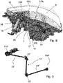
- the cab-over engine truck 1 comprises an adjustment mechanism 17 having a first end 17A engaging the vertical positioning adjustment member 9 and a first end 17B the horizontal positioning adjustment member 10.
- Second ends 18A, 18B adjustment mechanism 17 can be operated upon by an operator e.g. via an adjustment tool 19 (see Figure 7 ) for adjusting the vertical position of the high beam and/or a low beam and a horizontal positioning adjustment member for adjusting the horizontal position of the high beam and/or a low beam.
- the adjustment mechanism 17 comprises flexible cables 19, 20 extending from the second ends 18A, 18B of the adjustment mechanism 17 to the first ends 17A, 17B of the adjustment mechanism 17.
- the invention is not restricted to the use of flexible cables as means for transferring the adjustment by the operator from the second ends to the first ends of the adjustment mechanism, but any other means, such as rods 21' having gear heads 22' in engagement with each other as shown in Figure 9 can be used for transferring the adjustment by the operator from the second end 18A' to the first end 17A' of the adjustment mechanism 17'.
Landscapes
- Engineering & Computer Science (AREA)
- Mechanical Engineering (AREA)
- Chemical & Material Sciences (AREA)
- Combustion & Propulsion (AREA)
- Transportation (AREA)
- Lighting Device Outwards From Vehicle And Optical Signal (AREA)
Abstract
Description
- The invention relates to a cab-over engine truck having a front side, a chassis, an engine compartment and a driver cabin at least partially positioned over the engine compartment, the driver cabin including an cabin part that is tiltable with regard to the chassis to allow access to the engine compartment by being hinged about a horizontal axis arranged at the front side, the chassis comprising a chassis part that remains associated with the chassis when the cabin part is tilted, the chassis part and/or cabin part having a front section carrying a headlight unit for producing a high beam and/or a low beam, the headlight unit comprising a vertical positioning adjustment member for adjusting the vertical position of the high beam and/or a low beam and a horizontal positioning adjustment member for adjusting the horizontal position of the high beam and/or a low beam.
- Such a motor vehicle is for example known from
EP3421335A1 . According the legislations e.g. the low beam of a cab-over engine truck needs to be aimed to the road in a downwards inclination angle within a certain legal boundaries which usually will be controlled and adjusted by the approval agencies yearly during vehicle technical controls or during delivery of the cab-over engine truck by the dealers to the customers. In the cab-over engine truck known fromEP3421335A1 which includes an cabin part that is tiltable with regard to the chassis to allow access to the engine compartment adjustment of the vertical and/or horizontal position of the high beam and/or a low beam cannot be effected when the cabin part is tilted since in this tilted position the center of gravity of the driver cabin of the cab-over engine truck is displaced from the center of gravity when the driver cabin is positioned in the usual driving position of the cab-over engine truck. For this reason, in the cab-over engine truck known fromEP3421335A1 service caps are provided in side walls of the step region, the step region comprising the steps leading to the door opening of the driver cabin. The service caps are provided behind the headlight unit and can be opened for accessing the horizontal and vertical positioning adjustment members of the headlight unit. However, adjustment of the vertical and/or horizontal position of the high beam and/or a low beam in this manner is laborious since reaching the horizontal and vertical positioning adjustment members of the headlight unit can be difficult for an operator. - It is an object of the present invention to provide a cab-over engine truck in which adjustment of the vertical and/or horizontal position of the high beam and/or a low beam of a headlight unit can effected in a less laborious manner.
- According to the invention this object is obtained by providing a cab-over engine truck having a front side, a chassis, an engine compartment and a driver cabin at least partially positioned over the engine compartment, the driver cabin including an cabin part that is tiltable with regard to the chassis to allow access to the engine compartment by being hinged about a horizontal axis arranged at the front side, the chassis comprising a chassis part that remains associated with the chassis when the cabin part is tilted, the chassis part and/or cabin part having a front section carrying a headlight unit for producing a high beam and/or a low beam, the headlight unit comprising a vertical positioning adjustment member for adjusting the vertical position of the high beam and/or a low beam and a horizontal positioning adjustment member for adjusting the horizontal position of the high beam and/or a low beam, characterized in that the cab-over engine truck comprises an adjustment mechanism having first ends engaging the vertical positioning adjustment member and the horizontal positioning adjustment member and second ends for being operated by an operator, and in that the front side of the chassis part and/or cabin part comprises an adjustment mechanism access opening for allowing access to the second ends of the adjustment mechanism. By using an adjustment mechanism access opening at the front side of the chassis part and/or cabin part the second ends of the adjustment mechanism can be easily accessed by an operator thereby making the operation of adjusting the horizontal and/or vertical position of the high beam and/or a low beam more easy.
- In an embodiment of a cab-over engine truck according to the invention the adjustment mechanism access opening is positioned adjacent the headlight unit. By positioning the adjustment mechanism access opening adjacent the headlight unit the operator can easily visually check whether or not operating the second ends of the adjustment mechanism is changing the horizontal and/or vertical position of the high beam and/or a low beam. Alternatively, the adjustment mechanism access opening is integrally arranged in the headlight unit. It is then preferred, when the adjustment mechanism access opening is covered with a removable cover to protect the second ends of the adjustment mechanism from environmental influences, in particular during driving of the cab-over engine truck.
- In a further embodiment of a cab-over engine truck according to the invention the front section of the chassis part and/or cabin part comprises a headlight washer unit for washing a front of the headlight unit, the headlight washer unit being positioned adjacent the headlight unit and having a headlight washer and a headlight washer cap, the headlight washer cap being configured to be positioned in either an inoperative position flush with the front of the headlight unit and covering the headlight washer or an operative position in which the headlight washer cap exposes the headlight washer, the headlight washer being configured to be positioned in either an inoperative position covered by the headlight washer cap when in inoperative position or an operative position in which the headlight washer extends in a forwards direction beyond the headlight washer cap in its operative position, the adjustment mechanism access opening being arranged behind the headlight washer cap. In this manner the space behind the headlight washer cap also functions as adjustment mechanism access opening and thus no separate adjustment mechanism access opening needs to be provided in the chassis part and/or cabin part. It is then preferred when the headlight washer cap is configured for being positioned in the operative position independent of the operational state of the headlight washer, in other words the headlight washer is configured for being deactivated when positioned in its operative position.
- In a further embodiment of a cab-over engine truck according to the invention the adjustment mechanism comprises flexible cables extending from the second ends of the adjustment mechanism to the first ends of the adjustment mechanism. By using flexible cables the adjustment mechanism can be realized in a relatively simple and robust manner.
- The invention will be further explained with reference to the Figures, in which a non-limiting exemplary embodiment of according to the invention is shown:
-
Fig. 1 schematically shows in side view an embodiment of a cab-over engine truck according to the invention in a position in which the cabin part of the driver cabin is tilted with regard to the chassis to allow access to the engine compartment; -
Fig. 2 schematically shows in side view the embodiment of a cab-over engine truck according toFigure 1 in a position in which the cabin part of the driver cabin is closed; -
Fig. 3 schematically shows in perspective a prior art cab-over engine truck comprising service caps are provided in side walls of the step region, which service caps can be opened for accessing adjustment members of a headlight unit; -
Fig. 4 schematically shows in perspective a headlight unit vertical with horizontal and vertical positioning adjustment members for adjusting the horizontal and vertical position of the high beam and/or a low beam, respectively; -
Fig. 5 schematically shows in front view an embodiment of a cab-over engine truck according to the invention comprising an adjustment mechanism access opening arranged behind the headlight washer cap, in which the headlight washer cap is positioned in its operative position; -
Fig. 6 schematically shows in front view the embodiment of a cab-over engine truck according toFigure 5 in which the headlight washer cap is positioned in its inoperative position flush with the front of the headlight unit; -
Fig. 7 schematically shows in front view the embodiment of a cab-over engine truck according toFigure 5 in which an adjustment tool is in engagement with the second ends of the adjustment mechanism; -
Fig. 8 schematically shows in perspective an embodiment of a cab-over engine truck according to the invention in which the adjustment mechanism comprises flexible cables extending from the second ends of the adjustment mechanism to the first ends of the adjustment mechanism; and -
Fig. 9 schematically shows in perspective an embodiment of a cab-over engine truck according to the invention comprising an alternative adjustment mechanism comprising rods having gear heads in engagement with each other. - In
Figures 1 and 2 an embodiment of a cab-overengine truck 1 is schematically shown in side view. The cab-overengine truck 1 has a front side F, a chassis C, anengine compartment 2 and adriver cabin 3 which is at least partially positioned over theengine compartment 2. - The
driver cabin 3 comprises ancabin part 4 that is tiltable with regard to the chassis C to allow access to theengine compartment 2 by being hinged about a horizontal axis H arranged at the front side F. The chassis C has achassis part 5 that remains associated with the chassis C when thecabin part 4 is tilted. InFigure 1 the situation is shown in which thecabin part 4 of thedriver cabin 3 is tilted to allow access to theengine compartment 2, while inFigure 2 thecabin part 4 is shown in closed position. Thedriver cabin 3 is further provided with adoor 6 for accessing thedriver cabin 3 and a number ofsteps 7 leading to thedoor 6 of thedriver cabin 3. - The invention will be described with regard to embodiments in which the
chassis part 5 has afront section 5F carrying aheadlight unit 8 for producing a high beam and/or a low beam and in the shown embodiment afog light 9. As shown inFigure 4 theheadlight unit 8 comprises a verticalpositioning adjustment member 9 for adjusting the vertical position of the high beam and/or a low beam and a horizontalpositioning adjustment member 10 for adjusting the horizontal position of the high beam and/or a low beam. The invention is also applicable to embodiments in which the headlight unit is arranged in the cabin part. - In
Figure 3 a part of a prior art cab-over engine truck known fromEP3421335A1 is schematically shown, which comprises service caps 11', 12' provided in side walls of the step region, which service caps can be opened for accessing adjustment members of a headlight unit in the cab-over engine truck known fromEP3421335A1 service caps are provided in side walls of the step region comprising steps 7' positioned below the door 6'. The service caps 11', 12' are provided behind the headlight unit and the fog light, respectively and can be opened to provide an adjustment mechanism access opening for accessing the horizontal and vertical positioning adjustment members of the headlight unit and for accessing the fog light. - In contrast to the prior art cab-over engine truck shown in
Figure 3 , according to the present invention the adjustmentmechanism access opening 13 is positioned adjacent theheadlight unit 8 at thefront side 5F of thechassis part 5. In the embodiment shown inFigures 5 to 8 thefront section 5F of thechassis part 5 comprises aheadlight washer unit 14 for washing a front of theheadlight unit 8. As indicated inFigure 8 , theheadlight washer unit 14 is positioned adjacent theheadlight unit 8 and comprises aheadlight washer cap 15 behind which aheadlight washer 16 is arranged. Theheadlight washer cap 15 is configured to be positioned in either an inoperative position flush with the front of the headlight unit 8 (indicated inFigures 6 and8 ) and covering theheadlight washer 16 or an operative position in which theheadlight washer cap 15 exposes the headlight washer 16 (as indicated inFigure 5 and 7 ). - As is usual in the art the
headlight washer 16 is configured to be positioned in either an inoperative position covered by theheadlight washer cap 15 when in inoperative position or an operative position in which the headlight washer 16 extends in a forwards direction beyond the headlight washercap 15 in its operative position. - In the embodiment shown in
Figures 5 to 8 the adjustmentmechanism access opening 13 is positioned adjacent theheadlight unit 8 behind theheadlight washer cap 15. Please note that the invention is not restricted to this embodiment, and that in other (not shown) embodiments the adjustment mechanism access opening can be integrally arranged in the headlight unit or can be provided at another position at the front side of the chassis part. In all the embodiments adjustmentmechanism access opening 13 is preferably covered with a removable cover. - In the embodiment shown in
Figures 5 to 8 , theheadlight washer cap 15 is configured for being positioned in the operative position independent of the operational state of theheadlight washer 16, in other words theheadlight washer 16 is configured for being deactivated when positioned in its operative position to allow undisturbed access to the adjustment mechanism access opening 13. - As indicated in
Figure 8 the cab-over engine truck 1 comprises anadjustment mechanism 17 having afirst end 17A engaging the verticalpositioning adjustment member 9 and afirst end 17B the horizontalpositioning adjustment member 10.Second ends 18B adjustment mechanism 17 can be operated upon by an operator e.g. via an adjustment tool 19 (seeFigure 7 ) for adjusting the vertical position of the high beam and/or a low beam and a horizontal positioning adjustment member for adjusting the horizontal position of the high beam and/or a low beam. In the embodiment shown inFigure 8 theadjustment mechanism 17 comprisesflexible cables second ends adjustment mechanism 17 to thefirst ends adjustment mechanism 17. However, the invention is not restricted to the use of flexible cables as means for transferring the adjustment by the operator from the second ends to the first ends of the adjustment mechanism, but any other means, such as rods 21' having gear heads 22' in engagement with each other as shown inFigure 9 can be used for transferring the adjustment by the operator from thesecond end 18A' to thefirst end 17A' of the adjustment mechanism 17'.
Claims (7)
- A cab-over engine truck having a front side, a chassis, an engine compartment and a driver cabin at least partially positioned over the engine compartment, the driver cabin including an cabin part that is tiltable with regard to the chassis to allow access to the engine compartment by being hinged about a horizontal axis arranged at the front side, the chassis comprising a chassis part that remains associated with the chassis when the cabin part is tilted, the chassis part and/or cabin part having a front section carrying a headlight unit for producing a high beam and/or a low beam, the headlight unit comprising a vertical positioning adjustment member for adjusting the vertical position of the high beam and/or a low beam and a horizontal positioning adjustment member for adjusting the horizontal position of the high beam and/or a low beam, characterized in that the cab-over engine truck comprises an adjustment mechanism having first ends engaging the vertical positioning adjustment member and the horizontal positioning adjustment member and second ends for being operated by an operator, and in that the front side of the chassis part and/or cabin part comprises an adjustment mechanism access opening for allowing access to the second ends of the adjustment mechanism.
- A cab-over engine truck according to claim 1, wherein the adjustment mechanism access opening is positioned adjacent the headlight unit.
- A cab-over engine truck according to claim 1, wherein the adjustment mechanism access opening is integrally arranged in the headlight unit.
- A cab-over engine truck according to claim 2 or 3, wherein the adjustment mechanism access opening is covered with a removable cover.
- A cab-over engine truck according to claim 4, wherein the front section of the chassis part and/or cabin part comprises a headlight washer unit for washing a front of the headlight unit, the headlight washer unit being positioned adjacent the headlight unit and having a headlight washer and a headlight washer cap, the headlight washer cap being configured to be positioned in either an inoperative position flush with the front of the headlight unit and covering the headlight washer or an operative position in which the headlight washer cap exposes the headlight washer, the headlight washer being configured to be positioned in either an inoperative position covered by the headlight washer cap when in inoperative position or an operative position in which the headlight washer extends in a forwards direction beyond the headlight washer cap in its operative position, the adjustment mechanism access opening being arranged behind the headlight washer cap.
- A cab-over engine truck according to claim 5, wherein headlight washer is configured for being deactivated when positioned in its operative position.
- A cab-over engine truck according to any one of the preceding claims, wherein the adjustment mechanism comprises flexible cables extending from the second ends of the adjustment mechanism to the first ends of the adjustment mechanism.
Applications Claiming Priority (1)
| Application Number | Priority Date | Filing Date | Title |
|---|---|---|---|
| NL2028239A NL2028239B1 (en) | 2021-05-19 | 2021-05-19 | A cab-over engine truck. |
Publications (3)
| Publication Number | Publication Date |
|---|---|
| EP4091880A1 true EP4091880A1 (en) | 2022-11-23 |
| EP4091880B1 EP4091880B1 (en) | 2025-08-13 |
| EP4091880C0 EP4091880C0 (en) | 2025-08-13 |
Family
ID=77627457
Family Applications (1)
| Application Number | Title | Priority Date | Filing Date |
|---|---|---|---|
| EP22173836.2A Active EP4091880B1 (en) | 2021-05-19 | 2022-05-17 | A cab-over engine truck |
Country Status (2)
| Country | Link |
|---|---|
| EP (1) | EP4091880B1 (en) |
| NL (1) | NL2028239B1 (en) |
Citations (6)
| Publication number | Priority date | Publication date | Assignee | Title |
|---|---|---|---|---|
| DE2804651A1 (en) * | 1977-02-03 | 1978-08-10 | Saab Scania Ab | ARRANGEMENT OF A FRONT LIGHT ON A CYCLED VEHICLE |
| JPH08268360A (en) * | 1995-03-31 | 1996-10-15 | Suzuki Motor Corp | Headlight tilting device for scooter type vehicles |
| DE102004061483A1 (en) * | 2004-12-21 | 2006-06-29 | Hella Kgaa Hueck & Co. | Headlight for vehicles has first and second adjusting elements, which can be adjusted in opposite directions so that vertical or horizontal axis run orthogonal to first bearing point |
| TW201313531A (en) * | 2011-09-20 | 2013-04-01 | Honda Motor Co Ltd | Optical axis adjustment device of vehicle-use lighting device |
| US20140029278A1 (en) * | 2012-07-20 | 2014-01-30 | Burton Technologies, Llc | Synchronized lamp adjuster |
| EP3421335A1 (en) | 2017-06-29 | 2019-01-02 | Daf Trucks N.V. | Commercial motor vehicle |
-
2021
- 2021-05-19 NL NL2028239A patent/NL2028239B1/en active
-
2022
- 2022-05-17 EP EP22173836.2A patent/EP4091880B1/en active Active
Patent Citations (6)
| Publication number | Priority date | Publication date | Assignee | Title |
|---|---|---|---|---|
| DE2804651A1 (en) * | 1977-02-03 | 1978-08-10 | Saab Scania Ab | ARRANGEMENT OF A FRONT LIGHT ON A CYCLED VEHICLE |
| JPH08268360A (en) * | 1995-03-31 | 1996-10-15 | Suzuki Motor Corp | Headlight tilting device for scooter type vehicles |
| DE102004061483A1 (en) * | 2004-12-21 | 2006-06-29 | Hella Kgaa Hueck & Co. | Headlight for vehicles has first and second adjusting elements, which can be adjusted in opposite directions so that vertical or horizontal axis run orthogonal to first bearing point |
| TW201313531A (en) * | 2011-09-20 | 2013-04-01 | Honda Motor Co Ltd | Optical axis adjustment device of vehicle-use lighting device |
| US20140029278A1 (en) * | 2012-07-20 | 2014-01-30 | Burton Technologies, Llc | Synchronized lamp adjuster |
| EP3421335A1 (en) | 2017-06-29 | 2019-01-02 | Daf Trucks N.V. | Commercial motor vehicle |
Also Published As
| Publication number | Publication date |
|---|---|
| EP4091880B1 (en) | 2025-08-13 |
| EP4091880C0 (en) | 2025-08-13 |
| NL2028239B1 (en) | 2022-12-05 |
Similar Documents
| Publication | Publication Date | Title |
|---|---|---|
| EP2765242B1 (en) | Small-sized hydraulic excavator | |
| US2699223A (en) | Cab over engine vehicle | |
| EP3501899B1 (en) | Cutline gasket for external side mirror | |
| US20200086796A1 (en) | Camera assembly for an industrial vehicle cab | |
| CN110366505A (en) | Industrial vehicle cab including step lighting system, body component with lighting system and related industrial vehicle | |
| EP1079030B1 (en) | Work vehicle | |
| US3946826A (en) | Vehicle dash assembly | |
| EP3028901A1 (en) | Work vehicle | |
| EP4091880B1 (en) | A cab-over engine truck | |
| US20070138224A1 (en) | Actuating device | |
| GB2418182A (en) | Vehicle with tiltable cab mounted on chassis | |
| US7472946B2 (en) | Truck architecture | |
| EP3312077B1 (en) | Work vehicle | |
| AU2007326488B2 (en) | Sound-insulation structure for cab-over-engine truck | |
| DE102020124730B3 (en) | Scoop storage compartment for a cockpit of a motor vehicle | |
| JP7405533B2 (en) | Vehicle imaging unit | |
| JP2017044636A (en) | Mounting structure of radar | |
| AT524778B1 (en) | DRIVER'S CAB OF A TRACTION VEHICLE | |
| CN117141384A (en) | HUD device for vehicle and vehicle | |
| DE102007013810A1 (en) | Work light for e.g. passenger car, has evaluating unit that evaluates input signals, and tilting unit that tilts lights based on evaluation, where light is independently rotated, and evaluating unit is attached to bus system of machine | |
| CN210882364U (en) | Working vehicle | |
| JP5115738B2 (en) | Motorcycle with garage opener communication device | |
| KR101878058B1 (en) | Aiming system of head lamp for vehicle and designing method therof | |
| JP7452365B2 (en) | industrial vehicle | |
| WO2026045890A1 (en) | All-terrain vehicle |
Legal Events
| Date | Code | Title | Description |
|---|---|---|---|
| PUAI | Public reference made under article 153(3) epc to a published international application that has entered the european phase |
Free format text: ORIGINAL CODE: 0009012 |
|
| STAA | Information on the status of an ep patent application or granted ep patent |
Free format text: STATUS: THE APPLICATION HAS BEEN PUBLISHED |
|
| AK | Designated contracting states |
Kind code of ref document: A1 Designated state(s): AL AT BE BG CH CY CZ DE DK EE ES FI FR GB GR HR HU IE IS IT LI LT LU LV MC MK MT NL NO PL PT RO RS SE SI SK SM TR |
|
| STAA | Information on the status of an ep patent application or granted ep patent |
Free format text: STATUS: REQUEST FOR EXAMINATION WAS MADE |
|
| 17P | Request for examination filed |
Effective date: 20230227 |
|
| RBV | Designated contracting states (corrected) |
Designated state(s): AL AT BE BG CH CY CZ DE DK EE ES FI FR GB GR HR HU IE IS IT LI LT LU LV MC MK MT NL NO PL PT RO RS SE SI SK SM TR |
|
| P01 | Opt-out of the competence of the unified patent court (upc) registered |
Effective date: 20230505 |
|
| REG | Reference to a national code |
Ref country code: DE Ref legal event code: R079 Free format text: PREVIOUS MAIN CLASS: B60Q0001000000 Ipc: B62D0033067000 Ref country code: DE Ref legal event code: R079 Ref document number: 602022019255 Country of ref document: DE Free format text: PREVIOUS MAIN CLASS: B60Q0001000000 Ipc: B62D0033067000 |
|
| RIC1 | Information provided on ipc code assigned before grant |
Ipc: B60Q 1/068 20060101ALI20241213BHEP Ipc: B60Q 1/00 20060101ALI20241213BHEP Ipc: B62D 33/067 20060101AFI20241213BHEP |
|
| GRAP | Despatch of communication of intention to grant a patent |
Free format text: ORIGINAL CODE: EPIDOSNIGR1 |
|
| STAA | Information on the status of an ep patent application or granted ep patent |
Free format text: STATUS: GRANT OF PATENT IS INTENDED |
|
| GRAJ | Information related to disapproval of communication of intention to grant by the applicant or resumption of examination proceedings by the epo deleted |
Free format text: ORIGINAL CODE: EPIDOSDIGR1 |
|
| STAA | Information on the status of an ep patent application or granted ep patent |
Free format text: STATUS: REQUEST FOR EXAMINATION WAS MADE |
|
| INTG | Intention to grant announced |
Effective date: 20250129 |
|
| INTC | Intention to grant announced (deleted) | ||
| GRAP | Despatch of communication of intention to grant a patent |
Free format text: ORIGINAL CODE: EPIDOSNIGR1 |
|
| STAA | Information on the status of an ep patent application or granted ep patent |
Free format text: STATUS: GRANT OF PATENT IS INTENDED |
|
| INTG | Intention to grant announced |
Effective date: 20250324 |
|
| GRAS | Grant fee paid |
Free format text: ORIGINAL CODE: EPIDOSNIGR3 |
|
| GRAA | (expected) grant |
Free format text: ORIGINAL CODE: 0009210 |
|
| STAA | Information on the status of an ep patent application or granted ep patent |
Free format text: STATUS: THE PATENT HAS BEEN GRANTED |
|
| AK | Designated contracting states |
Kind code of ref document: B1 Designated state(s): AL AT BE BG CH CY CZ DE DK EE ES FI FR GB GR HR HU IE IS IT LI LT LU LV MC MK MT NL NO PL PT RO RS SE SI SK SM TR |
|
| REG | Reference to a national code |
Ref country code: GB Ref legal event code: FG4D |
|
| REG | Reference to a national code |
Ref country code: CH Ref legal event code: EP |
|
| REG | Reference to a national code |
Ref country code: DE Ref legal event code: R096 Ref document number: 602022019255 Country of ref document: DE |
|
| REG | Reference to a national code |
Ref country code: IE Ref legal event code: FG4D |
|
| U01 | Request for unitary effect filed |
Effective date: 20250827 |
|
| U07 | Unitary effect registered |
Designated state(s): AT BE BG DE DK EE FI FR IT LT LU LV MT NL PT RO SE SI Effective date: 20250902 |
|
| P04 | Withdrawal of opt-out of the competence of the unified patent court (upc) registered |
Free format text: CASE NUMBER: UPC_APP_77954_1/2023 Effective date: 20250902 |
|
| PG25 | Lapsed in a contracting state [announced via postgrant information from national office to epo] |
Ref country code: IS Free format text: LAPSE BECAUSE OF FAILURE TO SUBMIT A TRANSLATION OF THE DESCRIPTION OR TO PAY THE FEE WITHIN THE PRESCRIBED TIME-LIMIT Effective date: 20251213 |
|
| PG25 | Lapsed in a contracting state [announced via postgrant information from national office to epo] |
Ref country code: NO Free format text: LAPSE BECAUSE OF FAILURE TO SUBMIT A TRANSLATION OF THE DESCRIPTION OR TO PAY THE FEE WITHIN THE PRESCRIBED TIME-LIMIT Effective date: 20251113 |
|
| PG25 | Lapsed in a contracting state [announced via postgrant information from national office to epo] |
Ref country code: HR Free format text: LAPSE BECAUSE OF FAILURE TO SUBMIT A TRANSLATION OF THE DESCRIPTION OR TO PAY THE FEE WITHIN THE PRESCRIBED TIME-LIMIT Effective date: 20250813 |
|
| PG25 | Lapsed in a contracting state [announced via postgrant information from national office to epo] |
Ref country code: GR Free format text: LAPSE BECAUSE OF FAILURE TO SUBMIT A TRANSLATION OF THE DESCRIPTION OR TO PAY THE FEE WITHIN THE PRESCRIBED TIME-LIMIT Effective date: 20251114 |
|
| PG25 | Lapsed in a contracting state [announced via postgrant information from national office to epo] |
Ref country code: PL Free format text: LAPSE BECAUSE OF FAILURE TO SUBMIT A TRANSLATION OF THE DESCRIPTION OR TO PAY THE FEE WITHIN THE PRESCRIBED TIME-LIMIT Effective date: 20250813 |
|
| PG25 | Lapsed in a contracting state [announced via postgrant information from national office to epo] |
Ref country code: RS Free format text: LAPSE BECAUSE OF FAILURE TO SUBMIT A TRANSLATION OF THE DESCRIPTION OR TO PAY THE FEE WITHIN THE PRESCRIBED TIME-LIMIT Effective date: 20251113 |
|
| PG25 | Lapsed in a contracting state [announced via postgrant information from national office to epo] |
Ref country code: ES Free format text: LAPSE BECAUSE OF FAILURE TO SUBMIT A TRANSLATION OF THE DESCRIPTION OR TO PAY THE FEE WITHIN THE PRESCRIBED TIME-LIMIT Effective date: 20250813 |
|
| PG25 | Lapsed in a contracting state [announced via postgrant information from national office to epo] |
Ref country code: SM Free format text: LAPSE BECAUSE OF FAILURE TO SUBMIT A TRANSLATION OF THE DESCRIPTION OR TO PAY THE FEE WITHIN THE PRESCRIBED TIME-LIMIT Effective date: 20250813 |
|
| PGFP | Annual fee paid to national office [announced via postgrant information from national office to epo] |
Ref country code: GB Payment date: 20260324 Year of fee payment: 5 |
|
| PG25 | Lapsed in a contracting state [announced via postgrant information from national office to epo] |
Ref country code: CZ Free format text: LAPSE BECAUSE OF FAILURE TO SUBMIT A TRANSLATION OF THE DESCRIPTION OR TO PAY THE FEE WITHIN THE PRESCRIBED TIME-LIMIT Effective date: 20250813 |
|
| PG25 | Lapsed in a contracting state [announced via postgrant information from national office to epo] |
Ref country code: SK Free format text: LAPSE BECAUSE OF FAILURE TO SUBMIT A TRANSLATION OF THE DESCRIPTION OR TO PAY THE FEE WITHIN THE PRESCRIBED TIME-LIMIT Effective date: 20250813 |
|
| PLBE | No opposition filed within time limit |
Free format text: ORIGINAL CODE: 0009261 |
|
| STAA | Information on the status of an ep patent application or granted ep patent |
Free format text: STATUS: NO OPPOSITION FILED WITHIN TIME LIMIT |
|
| REG | Reference to a national code |
Ref country code: CH Ref legal event code: L10 Free format text: ST27 STATUS EVENT CODE: U-0-0-L10-L00 (AS PROVIDED BY THE NATIONAL OFFICE) Effective date: 20260624 |
|
| U20 | Renewal fee for the european patent with unitary effect paid |
Year of fee payment: 5 Effective date: 20260527 |
|
| 26N | No opposition filed |
Effective date: 20260515 |