EP3028901A1 - Work vehicle - Google Patents
Work vehicle Download PDFInfo
- Publication number
- EP3028901A1 EP3028901A1 EP14828923.4A EP14828923A EP3028901A1 EP 3028901 A1 EP3028901 A1 EP 3028901A1 EP 14828923 A EP14828923 A EP 14828923A EP 3028901 A1 EP3028901 A1 EP 3028901A1
- Authority
- EP
- European Patent Office
- Prior art keywords
- tractor
- hood
- light
- constituted
- cabin
- Prior art date
- Legal status (The legal status is an assumption and is not a legal conclusion. Google has not performed a legal analysis and makes no representation as to the accuracy of the status listed.)
- Granted
Links
Images


Classifications
-
- B—PERFORMING OPERATIONS; TRANSPORTING
- B60—VEHICLES IN GENERAL
- B60R—VEHICLES, VEHICLE FITTINGS, OR VEHICLE PARTS, NOT OTHERWISE PROVIDED FOR
- B60R3/00—Arrangements of steps or ladders facilitating access to or on the vehicle, e.g. running-boards
-
- B—PERFORMING OPERATIONS; TRANSPORTING
- B60—VEHICLES IN GENERAL
- B60Q—ARRANGEMENT OF SIGNALLING OR LIGHTING DEVICES, THE MOUNTING OR SUPPORTING THEREOF OR CIRCUITS THEREFOR, FOR VEHICLES IN GENERAL
- B60Q1/00—Arrangement of optical signalling or lighting devices, the mounting or supporting thereof or circuits therefor
- B60Q1/0029—Spatial arrangement
- B60Q1/0035—Spatial arrangement relative to the vehicle
-
- B—PERFORMING OPERATIONS; TRANSPORTING
- B60—VEHICLES IN GENERAL
- B60Q—ARRANGEMENT OF SIGNALLING OR LIGHTING DEVICES, THE MOUNTING OR SUPPORTING THEREOF OR CIRCUITS THEREFOR, FOR VEHICLES IN GENERAL
- B60Q1/00—Arrangement of optical signalling or lighting devices, the mounting or supporting thereof or circuits therefor
- B60Q1/0029—Spatial arrangement
- B60Q1/0041—Spatial arrangement of several lamps in relation to each other
- B60Q1/0052—Spatial arrangement of several lamps in relation to each other concentric
-
- B—PERFORMING OPERATIONS; TRANSPORTING
- B60—VEHICLES IN GENERAL
- B60Q—ARRANGEMENT OF SIGNALLING OR LIGHTING DEVICES, THE MOUNTING OR SUPPORTING THEREOF OR CIRCUITS THEREFOR, FOR VEHICLES IN GENERAL
- B60Q1/00—Arrangement of optical signalling or lighting devices, the mounting or supporting thereof or circuits therefor
- B60Q1/02—Arrangement of optical signalling or lighting devices, the mounting or supporting thereof or circuits therefor the devices being primarily intended to illuminate the way ahead or to illuminate other areas of way or environments
- B60Q1/04—Arrangement of optical signalling or lighting devices, the mounting or supporting thereof or circuits therefor the devices being primarily intended to illuminate the way ahead or to illuminate other areas of way or environments the devices being headlights
- B60Q1/18—Arrangement of optical signalling or lighting devices, the mounting or supporting thereof or circuits therefor the devices being primarily intended to illuminate the way ahead or to illuminate other areas of way or environments the devices being headlights being additional front lights
-
- B—PERFORMING OPERATIONS; TRANSPORTING
- B60—VEHICLES IN GENERAL
- B60Q—ARRANGEMENT OF SIGNALLING OR LIGHTING DEVICES, THE MOUNTING OR SUPPORTING THEREOF OR CIRCUITS THEREFOR, FOR VEHICLES IN GENERAL
- B60Q1/00—Arrangement of optical signalling or lighting devices, the mounting or supporting thereof or circuits therefor
- B60Q1/02—Arrangement of optical signalling or lighting devices, the mounting or supporting thereof or circuits therefor the devices being primarily intended to illuminate the way ahead or to illuminate other areas of way or environments
- B60Q1/22—Arrangement of optical signalling or lighting devices, the mounting or supporting thereof or circuits therefor the devices being primarily intended to illuminate the way ahead or to illuminate other areas of way or environments for reverse drive
-
- B—PERFORMING OPERATIONS; TRANSPORTING
- B60—VEHICLES IN GENERAL
- B60Q—ARRANGEMENT OF SIGNALLING OR LIGHTING DEVICES, THE MOUNTING OR SUPPORTING THEREOF OR CIRCUITS THEREFOR, FOR VEHICLES IN GENERAL
- B60Q1/00—Arrangement of optical signalling or lighting devices, the mounting or supporting thereof or circuits therefor
- B60Q1/26—Arrangement of optical signalling or lighting devices, the mounting or supporting thereof or circuits therefor the devices being primarily intended to indicate the vehicle, or parts thereof, or to give signals, to other traffic
- B60Q1/2607—Arrangement of optical signalling or lighting devices, the mounting or supporting thereof or circuits therefor the devices being primarily intended to indicate the vehicle, or parts thereof, or to give signals, to other traffic comprising at least two indicating lamps
-
- B—PERFORMING OPERATIONS; TRANSPORTING
- B60—VEHICLES IN GENERAL
- B60Q—ARRANGEMENT OF SIGNALLING OR LIGHTING DEVICES, THE MOUNTING OR SUPPORTING THEREOF OR CIRCUITS THEREFOR, FOR VEHICLES IN GENERAL
- B60Q1/00—Arrangement of optical signalling or lighting devices, the mounting or supporting thereof or circuits therefor
- B60Q1/26—Arrangement of optical signalling or lighting devices, the mounting or supporting thereof or circuits therefor the devices being primarily intended to indicate the vehicle, or parts thereof, or to give signals, to other traffic
- B60Q1/2661—Arrangement of optical signalling or lighting devices, the mounting or supporting thereof or circuits therefor the devices being primarily intended to indicate the vehicle, or parts thereof, or to give signals, to other traffic mounted on parts having other functions
- B60Q1/2665—Arrangement of optical signalling or lighting devices, the mounting or supporting thereof or circuits therefor the devices being primarily intended to indicate the vehicle, or parts thereof, or to give signals, to other traffic mounted on parts having other functions on rear-view mirrors
-
- B—PERFORMING OPERATIONS; TRANSPORTING
- B60—VEHICLES IN GENERAL
- B60Q—ARRANGEMENT OF SIGNALLING OR LIGHTING DEVICES, THE MOUNTING OR SUPPORTING THEREOF OR CIRCUITS THEREFOR, FOR VEHICLES IN GENERAL
- B60Q1/00—Arrangement of optical signalling or lighting devices, the mounting or supporting thereof or circuits therefor
- B60Q1/26—Arrangement of optical signalling or lighting devices, the mounting or supporting thereof or circuits therefor the devices being primarily intended to indicate the vehicle, or parts thereof, or to give signals, to other traffic
- B60Q1/32—Arrangement of optical signalling or lighting devices, the mounting or supporting thereof or circuits therefor the devices being primarily intended to indicate the vehicle, or parts thereof, or to give signals, to other traffic for indicating vehicle sides, e.g. clearance lights
-
- B—PERFORMING OPERATIONS; TRANSPORTING
- B60—VEHICLES IN GENERAL
- B60Q—ARRANGEMENT OF SIGNALLING OR LIGHTING DEVICES, THE MOUNTING OR SUPPORTING THEREOF OR CIRCUITS THEREFOR, FOR VEHICLES IN GENERAL
- B60Q1/00—Arrangement of optical signalling or lighting devices, the mounting or supporting thereof or circuits therefor
- B60Q1/26—Arrangement of optical signalling or lighting devices, the mounting or supporting thereof or circuits therefor the devices being primarily intended to indicate the vehicle, or parts thereof, or to give signals, to other traffic
- B60Q1/34—Arrangement of optical signalling or lighting devices, the mounting or supporting thereof or circuits therefor the devices being primarily intended to indicate the vehicle, or parts thereof, or to give signals, to other traffic for indicating change of drive direction
- B60Q1/38—Arrangement of optical signalling or lighting devices, the mounting or supporting thereof or circuits therefor the devices being primarily intended to indicate the vehicle, or parts thereof, or to give signals, to other traffic for indicating change of drive direction using immovably-mounted light sources, e.g. fixed flashing lamps
-
- B—PERFORMING OPERATIONS; TRANSPORTING
- B60—VEHICLES IN GENERAL
- B60Q—ARRANGEMENT OF SIGNALLING OR LIGHTING DEVICES, THE MOUNTING OR SUPPORTING THEREOF OR CIRCUITS THEREFOR, FOR VEHICLES IN GENERAL
- B60Q2800/00—Features related to particular types of vehicles not otherwise provided for
- B60Q2800/20—Utility vehicles, e.g. for agriculture, construction work
-
- B—PERFORMING OPERATIONS; TRANSPORTING
- B60—VEHICLES IN GENERAL
- B60R—VEHICLES, VEHICLE FITTINGS, OR VEHICLE PARTS, NOT OTHERWISE PROVIDED FOR
- B60R1/00—Optical viewing arrangements; Real-time viewing arrangements for drivers or passengers using optical image capturing systems, e.g. cameras or video systems specially adapted for use in or on vehicles
- B60R1/12—Mirror assemblies combined with other articles, e.g. clocks
- B60R1/1207—Mirror assemblies combined with other articles, e.g. clocks with lamps; with turn indicators
Definitions
- the present invention relates to a work vehicle.
- Work vehicles for riding have a step with which a passenger gets on and off and are known.
- a work vehicle has one or more steps for a foot between the front wheel and the rear wheel and near the passenger door of the cabin.
- Patent Literature 1 shows it.
- the Working vehicle of Patent Literature 1 has a step provided below the lower end of the fender covering the rear wheel steps configured in a ladder shape. And with the step, the work vehicle is configured for easy getting on and off. However, the work vehicle requires caution for avoiding contact with the end of the fender and the foot of the driver at getting on and off. In additionally, the both side of steps are supported with side boards and it makes the area where the driver put a foot small.
- Patent Document 1 JP 2000-142112 A
- the above is a principal object of the present invention to improve the convenience in getting on and off.
- the present invention includes a working vehicle with a step for getting on and off in front of a rear wheel, said step comprising: a receiving portion for a foot of the operator; a front supporting portion supporting the front of the receiving portion; and a rear supporting portion supporting, wherein an end of the front supporting portion is connected to a cabin frame and another end is connected to an end face of the receiving portion where is on the working vehicle side, and wherein an end for the rear supporting portion is connected to a front end of a fender for a rear wheel and another end is connected to an end face of the receiving portion.
- the present invention includes the rear support portion which is formed along the tread surface of the rear wheel with the same radius of curvature of the fender.
- the present invention includes the front support portion which is connected to the receiving part in front of the front side of the cabin, and wherein the rear support portion is connected to the receiving portion at a position lower than the axle of the rear wheel.
- the present invention includes a plurality of triangle shaped through holes are formed in the receiving part, and wherein each side of through holes is arranged so as not to parallel to the crosswise direction of the receiving part.
- the front supporting portion is not connected with the front end of the receiving portion and the receiving portion is formed to an front end of the fender
- the front - back direction width of the receiving portion becomes wider than the width of the bottom part of left and right doors.
- the rear supporting portion is connected with the front end of the fender, it is not necessary for an operator to pay attention to hit the fender. Thus it improves convenience at getting on and off.
- the rear supporting portion and the fender are connected continuously, and it puts away an operator from paying attention to hit the fender at getting on and off. It improves convenience at getting on and off.
- the receiving portion is formed up to the backward behind the front end of the fender, and the front - back direction width of the receiving portion becomes wider than the width of the bottom part of left and right doors. It improves convenience at getting on and off.
- each side of through holes is arranged so as not to parallel to the crosswise direction of the receiving part, it increases the stability of the foot on the receiving portion. Thus, convenience for getting on and off is improved.
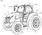
- a tractor 1 of an embodiment of a work vehicle according to the present invention will be described.
- the front, rear, right and left directions are defined based on the advancing direction of the tractor 1 as the front.
- the work vehicle according to the present invention is not limited to the tractor 1, but can be applied to vehicles across the board, such as other agricultural vehicles, construction vehicles, and industrial vehicles.
- the tractor 1 is equipped with various work machines (rotaries and the like) and performs various works.
- an engine 3 a hood 7, a transmission case, a front axle, a rear axle, each of which is not illustrated, a cabin 26, and a drive operating unit 37 are arranged on a machine body frame 2 of which the longitudinal direction is the back-and-front direction.
- a counterweight 6 and the like are mounted on the front end portion of the machine body frame 2 via a front hitch not illustrated.
- the engine 3 (see Figs. 3 and 4 ) is mounted on approximately the central portion of the machine body frame 2.
- the transmission case not illustrated that stores part of a power transmission mechanism of the tractor 1 is coupled with the rear end portion of the machine body frame 2.
- the front portion of the machine body frame 2 is supported with a pair of right and left front wheels 4 via the front axle not illustrated.
- the rear portion of the transmission case is supported with a pair of right and left rear wheels 5 via the rear axle not illustrated.
- the tractor 1 is such that the machine body frame 2 and the transmission case are integrally constituted and supported with the front wheels 4 and the rear wheels 5.
- the hood 7 and the like are arranged in such a manner as to cover the engine 3, thereby constituting the engine room.
- a front grille 8 and head lights 10 that light up in front of the tractor 1 are provided in the front of the hood 7.
- the drive operating unit 37 in which an operator rides so as to operate the tractor 1 is provided in the rear of the hood 7 and above the transmission case.
- the tractor 1 is such that the drive operating unit 37 is covered with a cabin 26.
- a work machine mounting device not illustrated is provided in back of the transmission case.
- the tractor 1 constituted in the aforementioned manner, after the power of the engine 3 is shifted by the power transmission mechanism, the power is transmitted to the pair of right and left front wheels 4 and the pair of right and left rear wheels 5 by way of the front axle and the rear axle.
- the tractor 1 travels by the rotational drive of the pair of right and left front wheels 4 and the pair of right and left rear wheels 5.
- the power is also transmitted to work machines such as a cultivator, which is not illustrated but mounted via the work machine mounting device provided in back of the transmission case.
- the counterweight 6 balances the weight of the work machine mounted on the work machine mounting device.
- the counterweight 6 is provided on the front end portion of the tractor 1.
- the counterweight 6 is formed in an approximately V shape for which the center in the right-left direction protrudes to the front when viewed from a plane.
- the upper side surface of the counterweight 6 is formed on an inclined surface that tilts downward to the center in the right-left direction. That is, the counterweight 6 is formed in a V shape when viewed from the front in the advancing direction.
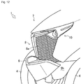
- the hood 7 constitutes the engine room in which the engine 3 and the like are arranged.
- the hood 7 is provided on the machine body frame 2 in which the engine 3 is arranged while the longitudinal direction thereof is regarded as the back-and-front direction, in such a manner as to cover a section leading from the front end portion of the machine body frame 2 to the cabin 26.
- An opening portion is formed in the front end of the hood 7.
- the front grille 8 is provided in the opening portion of the hood 7.
- the hood 7 is configured to rotate upward about the front end portion or the rear end as a fulcrum and make the engine room openable (see a black-painted arrow in Fig. 3 ).
- the hood 7 is constituted of an upper surface 7a, an upper left surface 7b, an upper right surface 7c, a left surface 7d, and a right surface 7e.
- respective surfaces adjacent to each other, out of the upper surface 7a, the upper left surface 7b, the upper right surface 7c, the left surface 7d, and the right surface 7e, are integrally formed.
- the upper surface 7a is formed in an approximately triangular shape whose vertex is directed to the front when viewed from a plane.
- the upper surface 7a constitutes part of the hood 7 in which the vertex is positioned approximately at the center in the back-forth direction of the hood 7 from the rear end of the hood 7.
- the upper surface 7a is formed on an inclined surface that tilts downward from the rear end to the front end of the hood 7.
- the upper left surface 7b constitutes part of the hood 7 leading from the rear end of the hood 7, which is the left side of the upper surface 7a, to the front end of the hood 7.
- the upper right surface 7c constitutes part of the hood 7 leading from the rear end of the hood 7, which is the right side of the upper surface 7a, to the front end of the hood 7.
- Part of the hood 7, which is constituted of the upper left surface 7b and the upper right surface 7c, is formed such that the width in the right-left direction gradually increases from the rear end to the front end of the hood 7, and the width in the right-left direction is gradually reduced from a midway portion.
- the hood 7 is formed in an approximately shell shape in which a left-side ridge line and a right-side ridge line converge at the center of the front end when viewed from a plane.
- the upper left surface 7b and the upper right surface 7c are constituted in such a manner as to be abutted to the upper surface 7a, leading from the rear end of the hood 7 to the vertex of the upper surface 7a. Then, the upper left surface 7b and the upper right surface 7c are constituted in such a manner as to be abutted to each other in the center in the right-left direction of the hood 7, leading from the vertex of the upper surface 7a to the front end of the hood 7.
- the upper left surface 7b is formed on an inclined surface that tilts downward to the left.
- the upper right surface 7c is formed on an inclined surface that tilts downward to the right.
- the upper left surface 7b and the upper right surface 7c are is formed on an inclined surface that tilts downward from the vertex of the upper surface 7a to the front end of the hood 7. Accordingly, part of the hood 7, which is constituted of the upper surface 7a, the upper left surface 7b, and the upper right surface 7c, is constituted such that the heights from the ground are reduced from the rear end to the front end, and from the center in the right-left direction to the right and left respectively.
- the left surface 7d constitutes part of the hood 7 in such a manner as to be abutted to the left-side end of the upper left surface 7b and face the machine body frame 2.
- the right surface 7e constitutes part of the hood 7 in such a manner as to be abutted to the right-side end of the upper right surface 7c and face the machine body frame 2.
- Discharge ports for cooling air that cools the engine 3 are formed in the left surface 7d and the right surface 7e. Notches facing the rear end of the hood 7 are formed at the upper end of the front end portion of the left surface 7d and the upper end of the front end portion of the right surface 7e.
- a notch portion 7f made up of the lower end of the upper left surface 7b and the notch of the left surface 7d is constituted on the left side of the front end portion of the hood 7.
- a notch portion 7g made up of the lower end of the upper right surface 7c and the notch of the right surface 7e is constituted on the right side of the front end portion of the hood 7.
- An instrumental panel 38 is connected to the rear end of the hood 7.
- the shape made up of the upper surface 7a, the upper left surface 7b, the upper right surface 7c, the left surface 7d, and the rear end of the right surface 7e of the hood 7 is formed approximately similarly to the shape of the front end of the instrumental panel 38. That is, the instrumental panel 38 is successively connected to the hood 7 without steps.
- an inclined surface 38a that tilts downward from the connection end with the hood 7 to the drive operating unit 37 in the cabin 26 is formed. That is, the instrumental panel 38 is constituted in such a manner that the height from the ground is not higher than that of the hood 7.
- the hood 7 becomes closer to the operator, the field of vision in front of the operator (including the left-side front and the right-side front) is blocked by the hood 7, which causes blind spots. That is, regarding the tractor 1, as the height of the hood 7 from the ground increases with respect to the height of the operator from the ground, the blind spots appear in the field of vision in front of the operator (hereinafter referred to as the height of each portion from the ground with respect to the height of the operator from the ground).
- a tractor 100 having a conventional hood shape that is not formed in a shell shape viewed from a plane is constituted such that both right and left ends of the front of the hood are the same height as that of the center of the front end portion of the hood when viewed from an operator. Accordingly, a blind spot B of the tractor 100 includes blind spots that are caused by the both right and left ends in front of the hood.
- the tractor 1 of the present embodiment is constituted in such a manner that the height of hood 7 from the ground is reduced as it advances from the front end of the hood 7 and the center in the right-left direction of the hood 7 to the right and left. Also, regarding the tractor 1, the height of both right and left ends of the front end of the hood 7 is lower than that of the center of the front end portion of the hood. Also, regarding the tractor 1, the height of the instrumental panel 38 from the ground is not higher than that of the hood 7. Accordingly, a blind spot A of the tractor 1 does not include a blind spot caused by both right and left ends of the front of the hood 7 and a blind spot caused by the instrumental panel 38. That is, in the blind spot A of the tractor 1, the blind spots that occur in the left-side front and the right-side front are decreased, compared with the blind spot B of the tractor 100.
- a proportion of the hood 7 to the field of vision in front, left-side front, and right-side front of the operator is decreased. Also, regarding the tractor 1, the proportion of the hood 7 to the field of vision in left-side front and in right-side front of the operator is decreased. Furthermore, regarding the tractor 1, a proportion of the instrumental panel 38 that occupies the field of vision in front of the operator is decreased. Consequently, the tractor 1 can decrease the blind spots that occur in front thereof.
- the front grille 8 covers a supply port through which the cooling air is taken out for the engine 3 and the like from the outside into the engine room.
- the front grille 8 is provided at an opening portion, which is a supply port formed in the front end portion of the hood 7.
- the front grille 8 is is constituted of resin or metal.
- a plurality of long holes 8a for which the longitudinal direction is the right-left direction are formed in the front grille 8.
- the tractor 1 can decrease resistance in the case where outside air passes through the front grille 8, compared with the case where the plurality of round holes are formed.
- the side covers 9 cover sections between the hood 7 on both right and left sides and the machine body frame 2.
- the side cover 9 is constituted of an upper side cover 9a and a lower side cover 9b.
- the upper side cover 9a is constituted of a reticular member and provided in such a manner as to cover a section ranging from the front wheels 4 to the cabin 26, on the lower side of the left surface 7d and the right surface 7e of the hood 7.
- the lower side cover 9b is provided in such a manner as to cover the machine body frame 2 on the lower side of the respective upper side covers 9a of the left surface 7d and the right surface 7e.
- the upper side cover 9a and the lower side cover 9b are fixed on the machine body frame 2.
- the tractor 1 can prevent dirt raised by the front wheels 4 during travelling from intruding into the machine body frame 2 or the interior of the engine room by means of the side covers 9 while releasing heat in the engine room from the upper side covers 9a to the outside.
- the tractor 1 can release the heat in the engine room from the upper side covers 9a to the outside or take in fresh air of the outside into the engine room.
- the head lights 10 will be described referring to Figs. 1 , 3 to 5 , 7 , and 13 to 15 .
- the head lights 10 light up in front of the tractor 1.
- the head lights 10 are provided on the left-side end and the right-side end of the front end portion of the hood 7. Specifically, the head lights 10 on both right and left sides are provided in the notch portions 7f and 7g that are constituted on the right side and left side of the front end portion of the hood 7.
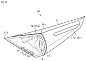
- the head light 10 includes a case 11, a reflector 12, a bulb 13, an LED flasher 14, and a head light cover 15.
- the head lights are configured to light up with side-marker lights 19 described later. That is, the tractor 1 is configured such that the head lights 10 light up after the side-marker lights 19 light up.
- the case 11 is a main constituent member of the head light 10, wherein the reflector 12, the bulb 13, the LED flasher 14, and the head light cover 15 are mounted.
- the case 11 is formed in an approximately triangular pyramid, which is mountable on the notch portions 7f and 7g of the hood 7 respectively.
- the case 11 is formed in such a manner that the end surface on the large-diameter side, which is a base of the approximately triangular pyramid, is opened. That is, a concave portion 11a for mounting the reflector 12, the bulb 13, or the like is formed in the case 11 while the end surface on the large-diameter side is regarded as the front end surface of the case 11.
- the cases 11 on the right and left are such that the concave portions 11 a formed on the front end surface are respectively directed to the front of the tractor 1 and assembled into the notch portions 7f and 7g.
- the cases 11 on the right and left are arranged such that, out of three vertices of the front end surface, which is the base of the approximately triangular pyramid, a first vertex 11d is directed to the center in the right-left direction of the hood 7, and a second vertex 11e is directed to an outer side in the right-left direction of the hood 7.
- the cases 11 on the right and left are assembled into the hood 7 in such a manner that an interval between the left-side surface of the case 11 on the left side and the right-side surface of the case 11 on the right side is approximately the same with the maximum width in the right-left direction of the hood 7.
- the cases 11 on the right and left are configured in such a manner that the vertex (the first vertex 11d) on the central side in the right-left direction of the hood 7 on the front end surface protrudes to the front end of the hood 7, with respect to the vertex
- the front end surfaces of the cases 11 on the right and left are formed in such a manner as to protrude to the front as they advance from the outer side in the right-left direction of the hood 7 to the central side in the right-left direction of the hood 7 when viewed from a plane. That is, the case 11 on the left side is formed in a shape that the front end surface thereof can be visually recognized form the left of the tractor 1, and the case 11 on the right side is formed in a shape that the front end surface thereof can be visually recognized from the right of the tractor 1.
- Reflectors 11b that condense light on the outside and reflect the light are provided on the left-side surface of the case 11 on the left side and on the right-side surface of the case 11 on the right side. It is noted that a slit 11c through which the light from the bulb 13 penetrates may be formed in the cases 11, in place of the reflector 11b.
- the reflector 12 reflects the light of the bulb 13 as a reflection means.
- the reflector 12 is formed in an approximately dome shape in which the light of the bulb 13 arranged approximately in its center is reflected in a constant direction.
- the reflectors 12 are respectively assembled in the concave portions 11a of the cases 11 on the right and left in such a manner that the light is reflected to the front of the tractor 1.
- the reflectors 12 are constituted in an approximately dome shape on the outer sides in the right-left direction of the hood 7 of the cases 11 and constituted leading from a portion constituted in an approximately dome shape to the end portion on the central side in the right-left direction of the hood 7 with regard to the cases 11.
- the bulb 13 generates light as a main light source body.
- the bulb 13 is constituted of light sources of arbitrary types such halogen lamps and HID lamps.
- the bulb 13 is assembled in a predetermined position approximately in the center of the reflector 12 constituted in an approximately dome shape. Accordingly, the greater part of the light generated from bulb 13 is irradiated to the front of the tractor 1 by the reflectors 12. In contrast, part of the light generated from bulb 13 is irradiated in the right-left direction of the tractor 1 by the reflectors 12 provided in or before reaching the end portion on the central side in the right-left direction of the hood 7 of the case 11.
- the LED flasher 14 generates light as an auxiliary light source body.
- the LED flasher 14 is constituted of a plurality of LEDs.
- the LED flasher 14 is provided in such a manner that respective LEDs are arranged side by side in a row on the front end surfaces of the cases 11 on the right and left. That is, the LED flasher 14 is such that the LEDs are arranged facing the center in the right-left direction of the front end from the outer sides in the right-left direction of the hood 7. Accordingly, the LED flasher 14 can be visually recognized not only from the front of the tractor 1 but also from the right and left (see Fig. 15 ).
- the LED flashers 14 are constituted in such a manner as to light up in combination with the side-marker lights 19 described later when the side-marker lights 19 light up. It is noted that, in the present embodiment, the LED flasher 14 is constituted of the plurality of LEDs, but may be constituted of other light sources.
- the head light cover 15 protects the reflector 12, the bulb 13, and the LED flasher 14 in the case 11.
- the head light cover 15 is constituted of materials through which the light of the bulb 13 and the LED flasher 14 penetrate.
- the head light covers 15 are respectively provided on the front end surfaces of the cases 11 on the right and left in such a manner as to cover the reflector 12, which is arranged in the concave portion 11a of the case 11, the bulb 13, and the LED flasher 14 (see hatching sections in Figs. 13 and 14 ).
- the tractor 1 irradiates the light to the front, the right, and the left by means of the reflection of light from the bulbs 13 by the reflectors 12, the reflection of light on the outside by the reflectors 11b of the cases 11 or the transmissive light from the slits 11c of the bulbs 13, and the LED flasher 14 provided on the front end surface of the cases 11 while irradiating the light in the advancing direction by the bulbs 13, which are the main light source bodies of the head lights 10 on the right and left.
- the reflection of the light of the bulbs 13 by the reflectors 12 from the front end surfaces of the head lights 10, which are visually recognizable from the lateral directions of the tractor 1, is not blocked by the hood 7 thanks to the notch portions 7f and 7g formed in the hood 7. Accordingly, visibility from the front, the right, and the left of the tractor 1 can be improved.
- the side view mirrors 16 are used to visually recognize the rear of the tractor 1.
- the right and left side view mirrors 16 are respectively provided on the bilateral ends of the upper portion of the front side surface 26b of the cabin 26.
- the side view mirror 16 includes a support arm 17, the front working light 22, a mirror portion 18, and the side-marker light 19.
- the right and left support arms 17 support the mirror portions 18 and the side-marker lights 19.
- the support arm 17 is constituted of a rectangular bar-shaped member when viewed from a cross section vertical to the axial direction thereof.
- the support arm 17 is formed in an approximately L shape having a bending portion 17a in the midway portion.
- the lateral ends of the long side portions of the support arms 17 are respectively fixed on the bilateral ends of the upper portions of the front side surface 26b of the cabin 26.
- the support arm 17 is formed in such a manner that a cross-sectional area Ar of the rectangular cross section is reduced when viewed from a cross section vertical to the axial direction thereof, as it advances from one lateral end to the lateral end (other lateral end) of the short side portion, on which the mirror portion 18 is supported. That is, the support arm 17 is configured in such a manner that weight per unit length is reduced as it advances from one lateral end fixed to the cabin 26 to the other lateral end. Furthermore, the support arm 17 is integrally formed with a beam 17b that couples one end and the other end in such a manner as to straddle over the bending portion 17a. Accordingly, regarding the support arm 17, while the rigidity of one lateral end portion and the rigidity of the bending portion 17a are secured, the weight of the other lateral end portion is reduced, so that the vibration of the other lateral end is suppressed.
- the left support arm 17 is provided in such a manner that the long side portion thereof faces from the front side surface 26b to the left-side front.
- the left support arm 17 is provided in such a manner that the long side portion thereof faces from the front side surface 26b to the right-side front.
- the support arms 17 on both right and left sides are provided in such a manner that the short side portions thereof face downward from the bending portion 17a.
- the support arms 17 are constituted such that a position in the back-forth direction of the bending portion 17a is placed in the vicinity of the rear end of the hood 7 (see Figs. 3 and 4 ), and a position in the right-left direction of the bending portion 17a is placed in an approximate center of the width of the rear wheels 5 (see Fig.
- the support arms 17 are constituted such that the mirror portions 18 are arranged at position separated from the cabin 26 (drive operating unit 37) to the front on both right and left sides.
- the mirror portions 18 hold mirrors.
- a mirror 18b is provided in the interior of a box-shaped case 18a having an opening portion.
- the mirror portions 18 are constituted such that the mirror 18b is provided in the opening portion of the case 18a, and the reflection surface of the mirror 18b can be visually recognized from the outside.
- the mirror portions 18 are connected to the short-side lateral end of the support arm 17 while the reflection surface of the mirror 18b faces the rear of the tractor 1. That is, the mirror portions 18 are arranged at position indicating the approximate width and height of the tractor 1.
- the mirror portions 18 are constituted such that the reflection surface of the mirror 18b can face in an arbitrary direction with respect to the support arm 17.
- the side-marker light 19 are used to visually recognize the width of the tractor 1.
- the side-marker light 19 are constituted of a plurality of LEDs.
- the side-marker light 19 are respectively provided in the cases 18a of right and left mirror portions 18 and on the surface (back surface) opposite to the opening portion. That is, the side-marker lights 19 are configured to light up to the front of the tractor 1 on the opposite side respect to the reflection surface of the mirrors 18b of the mirror portions 18 facing the rear of the tractor 1.
- the side-marker light 19 are provided at the mirror portions 18 on both right and left sides, so that the approximate width and height of the tractor 1 can be indicated. Also, the side-marker lights 19 can be used as a direction indicator by blinking one of right and left side-marker lights 19.
- the mirror portions 18 are arranged at positions of being disposed in front of the cabin 26 on both right and left sides and separated above the cabin 26. Accordingly, the tractor 1 can simultaneously represent the width and height of the tractor 1 while securing the field of vision in the rear.
- the side-marker lights 19 are such that the plurality of LEDs are arranged in an arbitrary mode in the mirror portions 18.
- the side-marker lights 19, which are the first embodiment of the side-marker light are constituted such that the plurality of LEDs are arranged side by side in the up-down direction on the rear surfaces of the cases 18a of the mirror portions 18.
- the side-marker lights 19 are formed in a spherical-surface shape smoothly expanded to the front of the tractor 1 on the rear surfaces of the cases 18a, so that the irradiation direction of each LED can be diffused in the up-down direction.
- the side-marker light 19 may be provided in the vicinity of the bending portion 17a of the support arm 17. Specifically, the side-marker light 19 is mounted by use of a surface that is constituted of the bending portion 17a and beam 17b of the support arm 17.
- the side-marker light 19 always lights up in a constant direction and at a constant position irrespective of the direction of the mirror portions 18. Accordingly, the tractor 1 can simultaneously represent the width and height while securing the field of vision in the rear.
- side-marker lights 20 which are the second embodiment of the side-marker light, are constituted such that the plurality of LEDs are arranged side by side in the right-left direction on the rear surfaces of the cases 18a of the mirror portions 18. Then, the side-marker lights 20 are formed in a spherical-surface shape smoothly expanded to the front of the tractor 1 on the rear surfaces of the cases 18a, so that the irradiation direction of each LED can be diffused in the right-left direction.
- side-marker lights 21, which are the third embodiment of the side-marker light are constituted such that the plurality of LEDs are arranged side by side in the up-down direction and the right-left direction on the rear surfaces of the cases 18a of the mirror portions 18.
- the side-marker lights 21 are formed in a spherical-surface shape smoothly expanded to the front of the tractor 1 on the rear surfaces of the cases 18a, so that the irradiation direction of each LED can be diffused in the up-down direction and the right-left direction.
- the irradiation direction of the side-marker lights 19 are set based on the shape of the case 18a of the mirror portion 18 and the arrangement of the side-marker lights 19. Accordingly, the tractor 1 can simultaneously represent the width and height while securing the field of vision in the rear.
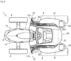
- the front working lights 22 light up in front of the tractor 1.
- the front working lights 22 are respectively provided on one side end portion (the lateral end portion of the long-side portion) of the right and left support arms 17.
- the front working light 22 includes an upper working light 23, a lower working light 24, and a front working light cover 25.
- the front working light cover 25 is formed of a material through which the light from the upper working light 23 and the lower working light 24 penetrates.
- the front working light cover 25 is constituted in such a manner as to cover the upper working light 23 and the lower working light 24 and couple the lower side surface of the support arm 17 with the front side surface 26b of the cabin 26 (see a hatching section in Fig. 16 ). That is, the front working light cover 25 protects the upper working light 23 and the lower working light 24 and improves the rigidity of the support arm 17. Accordingly, regarding the support arm 17, the rigidity of the one side end portion is further improved, thereby suppressing vibration.
- the front working light 22 is constituted such that the upper working light 23 and the lower working light 24 respectively illuminate an arbitrary range.
- the right and left front working lights 22 are constituted in such a manner that the upper working lights 23 illuminate irradiation ranges C respectively, which are the left-side front and the right-side front of the tractor 1 and that the right and left lower working lights 24 illuminate an irradiation range D, which is the front of the tractor 1.
- the right and left front working lights 22 may be constituted in such a manner that the upper working lights 23 illuminate the irradiation range D, which is the front of the tractor 1 and that the right and left lower working lights 24 illuminate the irradiation ranges C, which are the left-side front and the right-side front of the tractor 1.
- the irradiation ranges of the front working lights 22 are set in such a manner as not to include the side view mirrors 16 in the irradiation ranges. Also, regarding the tractor 1, the support arms 17 of the side view mirrors 16 is reinforced by the front working lights 22. Accordingly, the tractor 1 can improve the visual recognizability of the side-marker lights 19 while irradiating light in a wide range by means of the front working lights.
- the cabin 26 covers the drive operating unit 37.
- the cabin 26 is constituted in an approximately box shape formed by the front side surface 26b, a left side door 26c, a right side door 26d, a rear side surface 26e, and the ceiling 26f with a cabin frame 26a.
- An air-conditioner unit 27 and rear working lights 28 are included in the cabin 26.
- a frame body of the left side door 26c and the frame body of the right side door 26d, which are integrally formed, are fixed on the machine body frame 2, thereby constituting the frame 26a. That is, regarding the cabin 26, the frame bodies on both right and left sides of the front side surface 26b, the frame bodies on both right and left sides of the rear side surface 26e, and the frame bodies on both right and left sides of the ceiling 26f are integrally constituted as the frame body of the left side door 26c and the frame body of the right side door 26d respectively. Accordingly, regarding the cabin 26, the front side surface 26b, the rear side surface 26e, and the ceiling 26f are integrally constituted.
- the front side surface 26b of the cabin 26 is constituted in front of the drive operating unit 37 via the cabin frame 26a.
- Curved surface glass or resin, specifically, polycarbonate, acryl, or the like
- the curved surface glass constituting the front side surface 26b is formed in such a manner as to bend in a smooth arc shape in the right-left direction as the axial direction and in a smooth arc shape in the up-down direction as the axial direction (see a white-painted arrow in Fig. 20 ).
- the front side surface 26b is constituted of the curved surface glass formed in an approximately spherical-surface shape expanded in the front direction.
- a notch portion for arranging the instrumental panel 38 in the central portion in the right-left direction is formed on the curved surface glass of the front side surface 26b.
- the left side door 26c and the right side door 26d which can open and close the entire surface of the cabin 26, are respectively provided with the cabin frame 26a as the frame body on both right and left lateral surfaces of the cabin 26.
- the entire surfaces of the left side door 26c and the right side door 26d are constituted of the curved surface glass (or resin, specifically, polycarbonate, acryl, or the like) bent in a smooth arc shape in the up-down direction as the axial direction (see the white-painted arrow in Fig. 20 ).
- the rear end portions of the left side door 26c and the right side door 26d are connected to the cabin frame 26a via hinges 26g.
- External handles 26h are provided on the front end portions of the left side door 26c and the right side door 26d.
- Reinforcing bars 26j are provided on the left side door 26c and the right side door 26d.
- the reinforcing bars 26j are constituted of a plate-shaped member.
- the reinforcing bar 26j couples the hinge 26g with the external handle 26h on the side of the drive operating unit 37 in the up-down direction as a plate-width direction.
- Inner-side handles 26k that are used in opening and closing the left side door 26c and the right side door 26d are formed on the reinforcing bars 26j.
- the inner-side handle 26k branches in such a manner as to protrude from the midway portion on the side of the hinge 26g of the reinforcing bar 26j to the side of the drive operating unit 37 (operating seat 42).
- the inner-side handle 26k is formed until the inner-side handle 26k leads to the external handle 26h in parallel with the reinforcing bar 26j (see Fig. 28 ).
- the rear side surface 26e of the cabin 26 is constituted in back of the drive operating unit 37 via the cabin frame 26a.
- the curved surface glass (or resin, specifically, polycarbonate, acryl, or the like) that covers a section from the vicinity of the seating surface of the operating seat 42 of the drive operating unit 37 to the ceiling 26f of the cabin 26 is provided as rear glass on the rear side surface 26e.
- the curved surface glass constituting the rear side surface 26e is formed in such a manner that the both right and left end portions thereof are bent, so as to continuously connect the left side door 26c and the right side door 26d.
- the ceiling 26f of the cabin 26 is constituted on the upper end portions of the front side surface 26b, the left side door 26c, the right side door 26d, and the rear side surface 26e via the cabin frame 26a.
- Curved surface glass 26m (or resin, specifically, polycarbonate, acryl, or the like) that covers a section from the front end of the ceiling 26f to a position corresponding to the upper section of the operating seat 42 of the drive operating unit 37 is provided on the ceiling 26f.
- the curved surface glass 26m constituting the ceiling 26f is bent and formed in such a manner as to continuously connect the front side surface 26b. With this constitution in the aforementioned manner, the forward field of vision is secured, which makes it easy to visually recognize a work machine hoisted in loading work and the like and improves workability.
- the ceiling 26f is formed in a curved shape from the front end to the rear end thereof as a whole.
- the radius of curvature of the curved shape of the ceiling 26f increases as the ceiling 26f advances to the rear end in such a manner that the radius of curvature is varied from a radius R1 of curvature in the vicinity of the front end of the ceiling 26f to a radius R2 of curvature in the vicinity of the rear end of the ceiling 26f. That is, the ceiling 26f is constituted in an arc shape that approximates a clothoid curve represented by the following mathematical expression with a radius R of curvature and a length L of a curved line.
- RL A 2 A : Clothoid Parameter
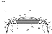
- the ceiling 26f can be constituted in such a manner that the height from the ground gently increases as the ceiling 26f advances to the rear end thereof. That is, it is constituted such that the thickness of the ceiling 26f increases in such a manner as to change from a thickness H1 in the vicinity of the front end of the ceiling 26f to a thickness H2 in the vicinity of the rear end of the ceiling 26f as the ceiling 26f advances to the rear end (see Fig. 21 ). Furthermore, an eaves portion 26n, wherein only the upper end of the rear end surface of the ceiling 26f protrudes to the rear with respect to the rear side surface 26e of the cabin 26, is formed on the ceiling 26f.
- the air-conditioner unit 27 is provided in the interior of the ceiling 26f, ranging from the rear end of the curved surface glass 26m to the rear end of the ceiling 26f. As illustrated in Fig. 22 , an introducing port 26p, through which the air-conditioner unit 27 takes in outside air, is provided in the eaves portion 26n of the rear end of the ceiling 26f. A louver is provided in the introducing port 26p. Accordingly, the tractor 1 can include the air-conditioner unit 27 in the interior of the ceiling 26f without causing part of the ceiling 26f to protrude or forming the introducing port separately.
- the tractor 1 is constituted of the curved surface glass or resin except for the cabin frame 26a and the rear portion of the ceiling 26f. Also, regarding the tractor 1, the visibility and rigidity of the cabin 26 are improved with monocoque structure in which the frame 26a integrally formed is successively coupled with the curved surface glass. Regarding the tractor 1, the opening and closing of the left side door 26c and the right side door 26d are facilitated, and the left side door 26c and the right side door 26d are reinforced with the reinforcing bars 26j. Accordingly, regarding the tractor 1, the front side surface 26b, the left side door 26c, the right side door 26d, the rear side surface 26e, and the ceiling 26f of the cabin 26 can be constituted of glass.
- the thickness of the ceiling 26f of the cabin 26 successively increases from the ceiling 26f of the cabin 26 to the rear end. Accordingly, the air-conditioner unit can be provided in the interior of the ceiling 26f without causing part of the ceiling 26f to protrude or separately forming the introducing port, through which the air-conditioner unit 27 takes in the outside air.
- the rear working lights 28 illuminate the rear of the tractor 1.
- the right and left rear working lights 28 are respectively provided both side end portions of the inclined surface of the rear end of the ceiling 26f.
- the introducing port 26p of the air-conditioner unit 27 is formed between the right and left rear working lights 28.
- the rear working light 28 includes an external working light 29 and an internal working light 30.
- the external working light 29 and the internal working light 30 are arranged side by side in the right-left direction in the eaves portion 26n of the rear end of the ceiling 26f.
- the rear working lights 28 are covered with rear working light covers 28a (see a hatching portion in Fig. 22 ) formed of a material through which the light from the external working light 29 and the internal working light 30 penetrate.
- the external working light 29 and the internal working light 30 are provided in such a manner as to face the rear via the eaves portion 26n from the interior of the ceiling 26f, so as not to protrude with respect to the eaves portion 26n.
- the rear working light covers 28a are provided in such a manner as to be flush with the eaves portion 26n.
- the rear working lights 28 are constituted such that the external working light 29 and the internal working light 30 respectively illuminate an arbitrary range.
- the rear working lights 28 are constituted such that the right and left external working lights 29 illuminate the rears E of the tractor 1, and the right and left internal working lights 30 illuminate the right and left rears F of the tractor 1 respectively (see white-painted arrows in Fig. 22 ).
- the rear working lights 28 may be constituted such that the right and left external working lights 29 illuminate the right and left rears F of the tractor 1, and the right and left internal working lights 30 illuminate the rears E of the tractor 1.
- the rear working lights 28 (the external working lights 29 and the internal working lights 30) are provided in such a manner as to face the rear from the interior of the ceiling 26f of the cabin 26, and the irradiation ranges of the external working lights 29 and the internal working lights 30 are set. Accordingly, a wide range can be irradiated by the rear working lights 28 without causing the rear working lights 28 to protrude from the cabin 26.
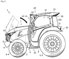
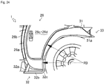
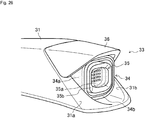
- fenders 31, steps 32, and combination lamps 33 will be described referring to Figs. 1 to 4 and 24 to 27 .
- the fenders 31 prevent dirt raised by the rotation of the rear wheels 5 from scattering.
- the fenders 31 are provided on both right and left sides of the cabin 26 in such a manner as to cover the tread surfaces (surfaces in contact with the ground) of the rear wheels 5 on the both right and left sides.
- the fenders 31 are provided along the tread surfaces of the rear wheels 5 from the vicinity of the rear side surface 26e of the cabin 26 to the vicinity of the machine body frame 2.
- the fenders 31 are constituted in such a manner that the central side in the right-left direction of the tractor 1 is abutted to the operating seat 42 in the cabin 26. That is, the right and left fenders 31 are arranged in the tractor 1 in such a manner as to sandwich the operating seat 42.
- the fenders 31 are integrally formed on the outside and inside of the cabin 26.
- the steps 32 are connected to the front ends (the side of the machine body frame 2) of the fenders 31.
- Inclined surfaces 31 a that tilt downward are formed on the rear ends (the side of t rear side surface 26e of the cabin 26) of the fenders 31.
- the combination lamps 33 are provided on the inclined surfaces 31a of the fenders 31.
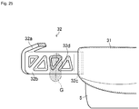
- the step 32 when an operator gets into the cabin 26, the step 32 is treaded by the leg G of the operator.
- the steps 32 are respectively provided in front of the rear wheels 5 and in the vicinity of the left side door 26c and the right side door 26d of the cabin 26.
- the step 32 is constituted of a front support portion 32a, a receiving portion 32b, and a rear support portion 32c.
- the front support portion 32a supports the front of the receiving portion 32b.
- One end of the front support portion 32a is coupled with the cabin frame 26a in the vicinity of the floor of the drive operating unit 37.
- the other end of the front support portion 32a is formed in such a manner as to lead from the cabin frame 26a to the front with respect to the front side surface 26b of the cabin 26.
- the other end of the front support portion 32a is coupled with the receiving portion 32b at a predetermined position of which the height is lower than that of the shaft of the rear wheels 5. That is, the front support portion 32a is formed in such a manner as to extend obliquely downward from the cabin frame 26a to the front.
- the other end of the front support portion 32a is coupled with the lateral surface on the side of the tractor 1. That is, the front support portion 32a is coupled with the receiving portion 32b in such a manner that the front end of the receiving portion 32b is released.
- the rear support portion 32c support the rear of the receiving portion 32b.
- the rear support portion 32c is coupled with the front end of the fender 31.
- the rear support portion 32c has approximately the same width as the width in the right-left direction on the outer side with respect to the cabin 26 of the front end of the fender 31 and is formed along the tread surface of the rear wheel 5 from the front end of the fender 31. Then, the rear support portion 32c is coupled with the receiving portion 32b at a predetermined position of which the height is lower than that of the shaft of the rear wheels 5.
- the rear support portion 32c is formed in such a manner as to successively extend from the front end of the fender 31 to the rear with respect to the front end of the fender 31 while having the same radius R3 of curvature as that of the fender 31.
- the receiving portion 32b is treaded by the leg G of the operator.
- the front and rear end portions of the receiving portion 32b are integrally coupled with the front support portion 32a and the rear support portion 32c.
- the receiving portion 32b is connected with the front support portion 32a forward with respect to the front side surface 26b of the cabin 26 and coupled with the fender 31 rearward with respect to the front end of the fender 31.
- the receiving portion 32b is formed in the same width in the right-left direction as the width of the rear support portion 32c in the right-left direction. That is, the receiving portion 32b is formed with approximately the same width as the width in the right-left direction on the outer side with respect to the cabin 26 of the front end of the fender 31.
- a plurality of triangular punch-out holes 32d are formed on the surface of the receiving portion 32b treaded by the leg G of the operator.
- the punch-out holes 32d are arranged in such a manner that each side is not in parallel to the right-left direction of the receiving portion 32b.
- the punch-out holes 32d are formed in such a manner that the sides of the adjacent punch-out holes 32d are in parallel to each other. That is, a beam-shaped portion between the punch-out holes 32d of the receiving portion 32b is formed in the oblique direction with respect to the longitudinal direction of the leg G of the operator who gets on or off.
- the width of the receiving portion 32b of the step 32 is formed wider than the width of the right and left doors in the neighborhood of the floor of the cabin.
- the front support portion 32a of the step 32 is coupled with the receiving portion 32b on the side of the tractor 1, so that the range, in which the leg G of the operator is laid, is not limited by the front support portion 32a.
- the rear support portion 32c of the step 32 is successively formed with fender 31, so that the leg G of the operator does not contact the front end of the fender 31.
- the lateral direction of the leg G of the operator is supported by a crosspiece. Accordingly, the steps 32 can expand the surface of the receiving portion 32b treaded by the leg G of the operator and improve the stability of the leg G and convenience when the operator gets on or off.
- the combination lamps 33 are made up of a combination of direction indicators 34 and brake lamps 35 and integrally formed.
- the combination lamps 33 are respectively provided at the rear ends of the fender 31 on both right and left sides in such a manner as to irradiate light to the rear.
- the combination lamps 33 are covered with combination lamp covers 36.
- the combination lamps 33 are formed in an approximately rectangular parallelepiped. Regarding the combination lamps 33, an outer circumferential surface 34a in the right-left direction and an outer edge portion 34b (hatching portions in Fig. 26 ) of the rear side surface are constituted as the direction indicators 34.
- the direction indicators 34 are constituted such that the outer circumferential surface 34a and the outer edge portion 34b emit light.
- the direction indicators 34 are configured to light up when the brakes are used.
- an inner side portion 35a of the outer edge portion 34b on the rear side surface is constituted as the brake lamp 35.
- the inner side portion 35a (the hatching portions in Fig. 26 ) emits light, and a reflector 35b is constituted on its periphery.
- the light source of the brake lamp 35 is constituted of LEDs. It is noted that the light source of the brake lamp 35 is not limited to the LEDs.
- the combination lamps 33 is constituted in dual structure in which the outer circumferential surface 34a and the outer edge portion 34b on the rear side surface, and the inner side portion 35a can individually light up.
- the front end portion thereof is inserted into a rear concave portion 31b formed on an inclined surface 31a of the fender 31 and provided approximately horizontally. That is, the combination lamps 33 are provided in such a manner as to be hidden in the interior of the fenders 31 from an upper part of the front end to a lower part of the rear end of the fenders 31.
- the lateral surface on the upper side thereof and part of the lateral surface (the outer circumferential surface 34a of the direction indicator 34) in the right-left direction are covered with the combination lamp cover 36.
- the combination lamp cover 36 is mounted on the inclined surface 31a of the fender 31.
- the combination lamp cover 36 is formed in such a manner as to extend with respect to the rear end of the combination lamp 33 while facing the rear from the midway portion of the inclined surface 31a of the fender 31.
- the rear end portion of the combination lamp cover 36 is formed in such a manner as to be inclined upward from the midway portion of the inclination (the inclined surface 31 a) of the rear end of the fender 31 when viewed from a lateral surface. That is, the combination lamps 33 is constituted in such a manner that the outer circumferential surface 34a of the direction indicator 34 can be visually recognized from between the inclination of the rear end of the combination lamp cover 36 with respect to the lateral side of the tractor 1 and the inclination of the fender 31.
- the mode of the direction indicator 34 and the brake lamp 35 in the combination lamp 33 is not limited to this.
- the combination lamp 33 as illustrated in Fig. 27(a) , it may be constituted such that the combination lamps 33 are equally divided into upper and lower sections, and that the direction indicators 34 are arranged on one of the upper and lower sections, and the brake lamps 35 are arranged on the other of the upper and lower sections. Also, as illustrated in Figs.
- the size of one of the upper and lower sections divided is larger than the size of the other of the upper and lower sections, and that the direction indicators 34 are arranged on one of the upper and lower sections, and the brake lamps 35 are arranged on the other of the upper and lower sections.
- the combination lamps 33 are equally or unequally divided into right and left sections, and that the direction indicators 34 are arranged on the left side surface of the combination lamp 33 on the left side and the right side surface of the combination lamp 33 on the right side.
- the drive operating unit 37 performs various operations used for operating the tractor 1.
- the drive operating unit 37 is provided in the interior of the cabin 26.
- the drive operating unit 37 includes the instrumental panel 38, a steering handle 40, the operating seat 42, an operating panel 43, and the like.
- the instrumental panel 38 is provided in the center in the right-left direction of the front in the cabin 26.
- the instrumental panel 38 is connected to the rear end of hood 7.
- the instrumental panel 38 is formed approximately in the same shape made up of the upper surface 7a, the upper left surface 7b, the upper right surface 7c, the left surface 7d, and the right surface 7e of the hood 7 (see Fig. 10 ). That is, the instrumental panel 38 is continuously connected to the rear end of the hood 7 without steps.
- the inclined surface 38a that tilts downward from the connection end with the hood 7 to the drive operating unit 37 in the cabin 26 is formed.
- the inclined surface 38a is formed in such a manner as to face the operator who sits on the operating seat 42.
- an approximately rectangular air-conditioner discharge opening 38b whose longitudinal direction is the right-left direction, is formed in the vicinity of the connection portion with the hood 7, that is, in the front end portion of the instrumental panel 38.
- a concave portion 38c is formed below the air-conditioner discharge opening 38b.
- a touch panel 39 is provided in the concave portion 38c.
- the touch panel 39 displays and operates various instruments and operating switches such as a travelling speeds, engine revolutions, fuel gauges, and water temperature gauges.
- the touch panel 39 is provided in such a manner as to form a gentle angle (in such a manner as to form a slight angle with respect to the horizontal surface) with respect to the inclined surface 38a of the instrumental panel 38. That is, the touch panel 39 is provided in the instrumental panel 38 in such a manner that the depth of the concave portion 38c increases as the concave portion 38c advances to the front. Accordingly, the touch panel 39 is constituted in such a manner that the light shined in from the front on a screen is not incident by means of the inclined surface 38a of the instrumental panel 38.
- the steering handle 40 is used to operate the tractor 1.
- the steering handle 40 is provided adjacent to the rear of the instrumental panel 38.
- the steering handle 40 is constituted in such a manner that the height thereof is approximately the same with that of the instrumental panel 38.
- a convex portion 40a is formed wherein the right side front and the left side front face the center of the steering handle 40.
- the steering handle 40 is supported by a steering column 41 via a plurality of column brackets 40b.
- a switch group 40c for performing various operations is provided in the column brackets 40b.
- the column brackets 40b are connected to the both sides in the right-left direction and the side (rear side) of the operating seat 42. That is, the column brackets 40b are not arranged on the side (front side) of the instrumental panel 38 of the steering handle 40.
- the operating seat 42 is provided in the rear of the steering handle 40 and between the right and left fenders 31. Also, the operating panel 43 that includes an operating lever of a variable speed gear is provided in one of the right and left fenders 31 of the operating seat 42. The operating panel 43 is arranged in a lateral concave portion 31c formed in the fender 31. That is, the operating panel 43 is integrally formed with the fender 31.
- the tractor 1 it is easy for the operator to operate the touch panel 39 provided in the instrumental panel 38. Also, regarding the tractor 1, even when the steering handle 40 is provided near to the touch panel 39, the operator easily recognizes the display of the touch panel 39. Accordingly, the tractor 1 can improve the operability of the touch panel 39 provided in the instrumental panel 38.
- the present invention can be applied to the technologies of work vehicles such as a tractor.
Abstract
Description
- The present invention relates to a work vehicle.
- Work vehicles for riding have a step with which a passenger gets on and off and are known. A work vehicle has one or more steps for a foot between the front wheel and the rear wheel and near the passenger door of the cabin. For example,
Patent Literature 1 shows it. - The Working vehicle of
Patent Literature 1 has a step provided below the lower end of the fender covering the rear wheel steps configured in a ladder shape. And with the step, the work vehicle is configured for easy getting on and off. However, the work vehicle requires caution for avoiding contact with the end of the fender and the foot of the driver at getting on and off. In additionally, the both side of steps are supported with side boards and it makes the area where the driver put a foot small. - Patent Document 1:
JP 2000-142112 A - The above is a principal object of the present invention to improve the convenience in getting on and off.
- Technical problems is as described above, it will be described means for solving problems as follows.
- The present invention includes a working vehicle with a step for getting on and off in front of a rear wheel, said step comprising: a receiving portion for a foot of the operator; a front supporting portion supporting the front of the receiving portion; and a rear supporting portion supporting, wherein an end of the front supporting portion is connected to a cabin frame and another end is connected to an end face of the receiving portion where is on the working vehicle side, and wherein an end for the rear supporting portion is connected to a front end of a fender for a rear wheel and another end is connected to an end face of the receiving portion.
- The present invention includes the rear support portion which is formed along the tread surface of the rear wheel with the same radius of curvature of the fender.
- The present invention includes the front support portion which is connected to the receiving part in front of the front side of the cabin, and wherein the rear support portion is connected to the receiving portion at a position lower than the axle of the rear wheel.
- The present invention includes a plurality of triangle shaped through holes are formed in the receiving part, and wherein each side of through holes is arranged so as not to parallel to the crosswise direction of the receiving part.
- Effects of the present invention are described below.
- According to the present invention, as the front supporting portion is not connected with the front end of the receiving portion and the receiving portion is formed to an front end of the fender, the front - back direction width of the receiving portion becomes wider than the width of the bottom part of left and right doors. As the rear supporting portion is connected with the front end of the fender, it is not necessary for an operator to pay attention to hit the fender. Thus it improves convenience at getting on and off.
- According to the present invention, the rear supporting portion and the fender are connected continuously, and it puts away an operator from paying attention to hit the fender at getting on and off. It improves convenience at getting on and off.
- According to the present invention, the receiving portion is formed up to the backward behind the front end of the fender, and the front - back direction width of the receiving portion becomes wider than the width of the bottom part of left and right doors. It improves convenience at getting on and off.
- According to the present invention, each side of through holes is arranged so as not to parallel to the crosswise direction of the receiving part, it increases the stability of the foot on the receiving portion. Thus, convenience for getting on and off is improved.
-
- [
Fig. 1] Fig. 1 is a perspective front view illustrating the entire constitution of a tractor according to an embodiment of the present invention. - [
Fig. 2] Fig. 2 is a perspective rear view illustrating the entire constitution of the tractor according to the embodiment of the present invention. - [
Fig. 3] Fig. 3 is a left side view illustrating the entire constitution of the tractor according to the embodiment of the present invention. - [
Fig. 4] Fig. 4 is a right side view illustrating the entire constitution of the tractor according to the embodiment of the present invention. - [
Fig. 5] Fig. 5 is a top view illustrating the entire constitution of the tractor according to the embodiment of the present invention. - [
Fig. 6] Fig. 6 is a bottom view illustrating the entire constitution of the tractor according to the embodiment of the present invention. - [
Fig. 7] Fig. 7 is a front view illustrating the entire constitution of the tractor according to the embodiment of the present invention. - [
Fig. 8] Fig. 8 is a rear view illustrating the entire constitution of the tractor according to the embodiment of the present invention. - [
Fig. 9] Fig. 9 is a partial enlarged side view illustrating the constitution of a hood of the tractor according to the embodiment of the present invention. - [
Fig. 10] Fig. 10 is a partial enlarged top view illustrating the constitution of the hood of the tractor according to the embodiment of the present invention. - [
Fig. 11] Fig. 11(a) is a view illustrating ranges representing blind spots from a drive operating unit of a tractor according to a conventional embodiment.Fig. 11(b) is a view illustrating ranges representing blind spots from a drive operating unit of the tractor according to the embodiment of the present invention. - [
Fig. 12] Fig. 12 is a partial enlarged perspective view illustrating the weight of the tractor and the constitution of a front grille according to the embodiment of the present invention. - [
Fig. 13] Fig. 13 is a partial enlarged front view illustrating the constitution of head lights according to an embodiment of the present invention. - [
Fig. 14] Fig. 14 is a partial enlarged side view illustrating the constitution of the head lights according to the embodiment of the present invention. - [
Fig. 15] Fig. 15 is a partial enlarged top view illustrating the irradiation direction of the LED flash of the head lights according to the embodiment of the present invention. - [
Fig. 16] Fig. 16 is a partial enlarged front view illustrating the constitution of side view mirrors, front working lights, and side-marker lights according to an embodiment of the present invention. - [
Fig. 17] Fig. 17 is a partial enlarged front view illustrating the constitution of the side view mirrors, the front working lights, and the side-marker lights according to another embodiment of the present invention. - [
Fig. 18] Fig. 18(a) is a partial enlarged view illustrating the irradiation direction of the side-marker lights according to a first embodiment of the present invention.Fig. 18(b) is a partial enlarged view illustrating the irradiation direction of the side-marker lights according to a second embodiment of the present invention.Fig. 18(c) is a partial enlarged view illustrating the side-marker lights according to a third embodiment of the present invention. - [
Fig. 19] Fig. 19 is a view illustrating ranges in which the front working lights of the tractor according to the embodiment of the present invention irradiate. - [
Fig. 20] Fig. 20 is a partial enlarged perspective front view illustrating the constitution of a cabin of the tractor according to the embodiment of the present invention. - [
Fig. 21] Fig. 21 is a partial enlarged side view illustrating the constitution of the cabin of the tractor according to the embodiment of the present invention. - [
Fig. 22] Fig. 22 is a partial enlarged rear view illustrating the constitution of the cabin of the tractor according to the embodiment of the present invention. - [
Fig. 23] Fig. 23 is a view illustrating ranges in which the rear working lights of the tractor according to the embodiment of the present invention irradiate. - [
Fig. 24] Fig. 24 is a partial enlarged side view illustrating the constitution of a fender and a step of the tractor according to the embodiment of the present invention. - [
Fig. 25] Fig. 25 is a partial enlarged top view illustrating the constitution of the step the tractor according to the embodiment of the present invention. - [
Fig. 26] Fig. 26 is a partial enlarged perspective rear view illustrating the constitution of a combination lamp of the tractor according to the embodiment of the present invention. - [
Fig. 27] Fig. 27(a) is a partial rear view illustrating the constitution of the combination lamp according to a first embodiment of the present invention.Fig. 27(b) is a partial rear view illustrating the constitution of the combination lamp according to a second embodiment of the present invention.Fig. 27(c) is a partial rear view illustrating the constitution of the combination lamp according to a third embodiment of the present invention.Fig. 27(d) is a partial rear view illustrating the constitution of the combination lamp according to a fourth embodiment of the present invention. - [
Fig. 28] Fig. 28 is a partial enlarged perspective view illustrating the constitution of the drive operating unit of the tractor according to the embodiment of the present invention. - Hereinafter, a
tractor 1 of an embodiment of a work vehicle according to the present invention will be described. In the following description, the front, rear, right and left directions are defined based on the advancing direction of thetractor 1 as the front. - First, the entire constitution of the
tractor 1 according to the present invention will be described referring toFigs. 1 to 8 . It is noted that the work vehicle according to the present invention is not limited to thetractor 1, but can be applied to vehicles across the board, such as other agricultural vehicles, construction vehicles, and industrial vehicles. - As illustrated in
Figs. 1 and2 , thetractor 1 is equipped with various work machines (rotaries and the like) and performs various works. Regarding thetractor 1, anengine 3, ahood 7, a transmission case, a front axle, a rear axle, each of which is not illustrated, acabin 26, and adrive operating unit 37 are arranged on amachine body frame 2 of which the longitudinal direction is the back-and-front direction. - A
counterweight 6 and the like are mounted on the front end portion of themachine body frame 2 via a front hitch not illustrated. The engine 3 (seeFigs. 3 and4 ) is mounted on approximately the central portion of themachine body frame 2. The transmission case not illustrated that stores part of a power transmission mechanism of thetractor 1 is coupled with the rear end portion of themachine body frame 2. Also, the front portion of themachine body frame 2 is supported with a pair of right and leftfront wheels 4 via the front axle not illustrated. The rear portion of the transmission case is supported with a pair of right and leftrear wheels 5 via the rear axle not illustrated. Thus, thetractor 1 is such that themachine body frame 2 and the transmission case are integrally constituted and supported with thefront wheels 4 and therear wheels 5. - In the
tractor 1, thehood 7 and the like are arranged in such a manner as to cover theengine 3, thereby constituting the engine room. Regarding thetractor 1, afront grille 8 andhead lights 10 that light up in front of thetractor 1 are provided in the front of thehood 7. In thetractor 1, thedrive operating unit 37 in which an operator rides so as to operate thetractor 1 is provided in the rear of thehood 7 and above the transmission case. Thetractor 1 is such that thedrive operating unit 37 is covered with acabin 26. Also, in thetractor 1, a work machine mounting device not illustrated is provided in back of the transmission case. - Regarding the
tractor 1 constituted in the aforementioned manner, after the power of theengine 3 is shifted by the power transmission mechanism, the power is transmitted to the pair of right and leftfront wheels 4 and the pair of right and leftrear wheels 5 by way of the front axle and the rear axle. Thetractor 1 travels by the rotational drive of the pair of right and leftfront wheels 4 and the pair of right and leftrear wheels 5. Also, regarding thetractor 1, after the power of theengine 3 is shifted by the power transmission mechanism, the power is also transmitted to work machines such as a cultivator, which is not illustrated but mounted via the work machine mounting device provided in back of the transmission case. - Next, the
counterweight 6, thehood 7, thefront grille 8, and side covers 9 will be described referring toFig. 1 . - As illustrated in
Figs. 1 ,3 ,4 , and5 , thecounterweight 6 balances the weight of the work machine mounted on the work machine mounting device. Thecounterweight 6 is provided on the front end portion of thetractor 1. Thecounterweight 6 is formed in an approximately V shape for which the center in the right-left direction protrudes to the front when viewed from a plane. Also, the upper side surface of thecounterweight 6 is formed on an inclined surface that tilts downward to the center in the right-left direction. That is, thecounterweight 6 is formed in a V shape when viewed from the front in the advancing direction. - With this constitution in the aforementioned manner, regarding the
tractor 1, when thehood 7 is opened and closed in such a manner that the rear end of thehood 7 faces the front, the front end portion of thehood 7 and thecounterweight 6 do not contact each other (seeFig. 3 ). - As illustrated in
Figs. 9 and10 , thehood 7 constitutes the engine room in which theengine 3 and the like are arranged. Thehood 7 is provided on themachine body frame 2 in which theengine 3 is arranged while the longitudinal direction thereof is regarded as the back-and-front direction, in such a manner as to cover a section leading from the front end portion of themachine body frame 2 to thecabin 26. An opening portion is formed in the front end of thehood 7. Thefront grille 8 is provided in the opening portion of thehood 7. Thehood 7 is configured to rotate upward about the front end portion or the rear end as a fulcrum and make the engine room openable (see a black-painted arrow inFig. 3 ). - The
hood 7 is constituted of anupper surface 7a, an upperleft surface 7b, an upperright surface 7c, aleft surface 7d, and aright surface 7e. In thehood 7, respective surfaces adjacent to each other, out of theupper surface 7a, the upperleft surface 7b, the upperright surface 7c, theleft surface 7d, and theright surface 7e, are integrally formed. - The
upper surface 7a is formed in an approximately triangular shape whose vertex is directed to the front when viewed from a plane. Theupper surface 7a constitutes part of thehood 7 in which the vertex is positioned approximately at the center in the back-forth direction of thehood 7 from the rear end of thehood 7. Theupper surface 7a is formed on an inclined surface that tilts downward from the rear end to the front end of thehood 7. - The upper
left surface 7b constitutes part of thehood 7 leading from the rear end of thehood 7, which is the left side of theupper surface 7a, to the front end of thehood 7. The upperright surface 7c constitutes part of thehood 7 leading from the rear end of thehood 7, which is the right side of theupper surface 7a, to the front end of thehood 7. Part of thehood 7, which is constituted of the upperleft surface 7b and the upperright surface 7c, is formed such that the width in the right-left direction gradually increases from the rear end to the front end of thehood 7, and the width in the right-left direction is gradually reduced from a midway portion. Then, thehood 7 is formed in an approximately shell shape in which a left-side ridge line and a right-side ridge line converge at the center of the front end when viewed from a plane. - The upper
left surface 7b and the upperright surface 7c are constituted in such a manner as to be abutted to theupper surface 7a, leading from the rear end of thehood 7 to the vertex of theupper surface 7a. Then, the upperleft surface 7b and the upperright surface 7c are constituted in such a manner as to be abutted to each other in the center in the right-left direction of thehood 7, leading from the vertex of theupper surface 7a to the front end of thehood 7. The upperleft surface 7b is formed on an inclined surface that tilts downward to the left. The upperright surface 7c is formed on an inclined surface that tilts downward to the right. In addition, the upperleft surface 7b and the upperright surface 7c are is formed on an inclined surface that tilts downward from the vertex of theupper surface 7a to the front end of thehood 7. Accordingly, part of thehood 7, which is constituted of theupper surface 7a, the upperleft surface 7b, and the upperright surface 7c, is constituted such that the heights from the ground are reduced from the rear end to the front end, and from the center in the right-left direction to the right and left respectively. - The
left surface 7d constitutes part of thehood 7 in such a manner as to be abutted to the left-side end of the upperleft surface 7b and face themachine body frame 2. Theright surface 7e constitutes part of thehood 7 in such a manner as to be abutted to the right-side end of the upperright surface 7c and face themachine body frame 2. Discharge ports for cooling air that cools theengine 3 are formed in theleft surface 7d and theright surface 7e. Notches facing the rear end of thehood 7 are formed at the upper end of the front end portion of theleft surface 7d and the upper end of the front end portion of theright surface 7e. In this manner, anotch portion 7f made up of the lower end of the upperleft surface 7b and the notch of theleft surface 7d is constituted on the left side of the front end portion of thehood 7. Also, anotch portion 7g made up of the lower end of the upperright surface 7c and the notch of theright surface 7e is constituted on the right side of the front end portion of thehood 7. - An
instrumental panel 38 is connected to the rear end of thehood 7. The shape made up of theupper surface 7a, the upperleft surface 7b, the upperright surface 7c, theleft surface 7d, and the rear end of theright surface 7e of thehood 7 is formed approximately similarly to the shape of the front end of theinstrumental panel 38. That is, theinstrumental panel 38 is successively connected to thehood 7 without steps. Also, regarding theinstrumental panel 38, aninclined surface 38a that tilts downward from the connection end with thehood 7 to thedrive operating unit 37 in thecabin 26 is formed. That is, theinstrumental panel 38 is constituted in such a manner that the height from the ground is not higher than that of thehood 7. - Regarding the
tractor 1, as thehood 7 becomes closer to the operator, the field of vision in front of the operator (including the left-side front and the right-side front) is blocked by thehood 7, which causes blind spots. That is, regarding thetractor 1, as the height of thehood 7 from the ground increases with respect to the height of the operator from the ground, the blind spots appear in the field of vision in front of the operator (hereinafter referred to as the height of each portion from the ground with respect to the height of the operator from the ground). - As illustrated in
Fig. 11(a) , atractor 100 having a conventional hood shape that is not formed in a shell shape viewed from a plane is constituted such that both right and left ends of the front of the hood are the same height as that of the center of the front end portion of the hood when viewed from an operator. Accordingly, a blind spot B of thetractor 100 includes blind spots that are caused by the both right and left ends in front of the hood. - As illustrated in
Fig. 11(b) , thetractor 1 of the present embodiment is constituted in such a manner that the height ofhood 7 from the ground is reduced as it advances from the front end of thehood 7 and the center in the right-left direction of thehood 7 to the right and left. Also, regarding thetractor 1, the height of both right and left ends of the front end of thehood 7 is lower than that of the center of the front end portion of the hood. Also, regarding thetractor 1, the height of theinstrumental panel 38 from the ground is not higher than that of thehood 7. Accordingly, a blind spot A of thetractor 1 does not include a blind spot caused by both right and left ends of the front of thehood 7 and a blind spot caused by theinstrumental panel 38. That is, in the blind spot A of thetractor 1, the blind spots that occur in the left-side front and the right-side front are decreased, compared with the blind spot B of thetractor 100. - With the constitution in the aforementioned manner, regarding the
tractor 1, a proportion of thehood 7 to the field of vision in front, left-side front, and right-side front of the operator is decreased. Also, regarding thetractor 1, the proportion of thehood 7 to the field of vision in left-side front and in right-side front of the operator is decreased. Furthermore, regarding thetractor 1, a proportion of theinstrumental panel 38 that occupies the field of vision in front of the operator is decreased. Consequently, thetractor 1 can decrease the blind spots that occur in front thereof. - As illustrated in
Fig. 12 , thefront grille 8 covers a supply port through which the cooling air is taken out for theengine 3 and the like from the outside into the engine room. Thefront grille 8 is provided at an opening portion, which is a supply port formed in the front end portion of thehood 7. Thefront grille 8 is is constituted of resin or metal. A plurality oflong holes 8a for which the longitudinal direction is the right-left direction are formed in thefront grille 8. - With the constitution in the aforementioned manner, a proportion of areas of the holes of the
front grille 8 per unit area increases, compared with the case where a plurality of round holes are formed. Accordingly, thetractor 1 can decrease resistance in the case where outside air passes through thefront grille 8, compared with the case where the plurality of round holes are formed. - As illustrated in
Fig. 9 , the side covers 9 cover sections between thehood 7 on both right and left sides and themachine body frame 2. Theside cover 9 is constituted of anupper side cover 9a and alower side cover 9b. Theupper side cover 9a is constituted of a reticular member and provided in such a manner as to cover a section ranging from thefront wheels 4 to thecabin 26, on the lower side of theleft surface 7d and theright surface 7e of thehood 7. Thelower side cover 9b is provided in such a manner as to cover themachine body frame 2 on the lower side of the respective upper side covers 9a of theleft surface 7d and theright surface 7e. Theupper side cover 9a and thelower side cover 9b are fixed on themachine body frame 2. - With the constitution in the aforementioned manner, regarding the
tractor 1, various apparatuses with regard to theengine 3 or the like that is not covered with thehood 7, and themachine body frame 2 are covered with theside cover 9 from the outside. Accordingly, thetractor 1 can prevent dirt raised by thefront wheels 4 during travelling from intruding into themachine body frame 2 or the interior of the engine room by means of the side covers 9 while releasing heat in the engine room from the upper side covers 9a to the outside. In addition, thetractor 1 can release the heat in the engine room from the upper side covers 9a to the outside or take in fresh air of the outside into the engine room. - Next, the head lights 10 will be described referring to
Figs. 1 ,3 to 5 ,7 , and13 to 15 . - As illustrated in
Figs. 1 ,3 to 5 , and7 , the head lights 10 light up in front of thetractor 1. The head lights 10 are provided on the left-side end and the right-side end of the front end portion of thehood 7. Specifically, the head lights 10 on both right and left sides are provided in thenotch portions hood 7. Thehead light 10 includes acase 11, areflector 12, abulb 13, anLED flasher 14, and a headlight cover 15. The head lights are configured to light up with side-marker lights 19 described later. That is, thetractor 1 is configured such that the head lights 10 light up after the side-marker lights 19 light up. - As illustrated in
Figs. 13 to 15 , thecase 11 is a main constituent member of thehead light 10, wherein thereflector 12, thebulb 13, theLED flasher 14, and the headlight cover 15 are mounted. Thecase 11 is formed in an approximately triangular pyramid, which is mountable on thenotch portions hood 7 respectively. Also, thecase 11 is formed in such a manner that the end surface on the large-diameter side, which is a base of the approximately triangular pyramid, is opened. That is, aconcave portion 11a for mounting thereflector 12, thebulb 13, or the like is formed in thecase 11 while the end surface on the large-diameter side is regarded as the front end surface of thecase 11. - The
cases 11 on the right and left are such that theconcave portions 11 a formed on the front end surface are respectively directed to the front of thetractor 1 and assembled into thenotch portions cases 11 on the right and left are arranged such that, out of three vertices of the front end surface, which is the base of the approximately triangular pyramid, afirst vertex 11d is directed to the center in the right-left direction of thehood 7, and asecond vertex 11e is directed to an outer side in the right-left direction of thehood 7. Also, thecases 11 on the right and left are assembled into thehood 7 in such a manner that an interval between the left-side surface of thecase 11 on the left side and the right-side surface of thecase 11 on the right side is approximately the same with the maximum width in the right-left direction of thehood 7. - The
cases 11 on the right and left are configured in such a manner that the vertex (thefirst vertex 11d) on the central side in the right-left direction of thehood 7 on the front end surface protrudes to the front end of thehood 7, with respect to the vertex - (the
second vertex 11e) on the outer side in the right-left direction of thehood 7. That is, the front end surfaces of thecases 11 on the right and left are formed in such a manner as to protrude to the front as they advance from the outer side in the right-left direction of thehood 7 to the central side in the right-left direction of thehood 7 when viewed from a plane. That is, thecase 11 on the left side is formed in a shape that the front end surface thereof can be visually recognized form the left of thetractor 1, and thecase 11 on the right side is formed in a shape that the front end surface thereof can be visually recognized from the right of thetractor 1. -
Reflectors 11b that condense light on the outside and reflect the light are provided on the left-side surface of thecase 11 on the left side and on the right-side surface of thecase 11 on the right side. It is noted that aslit 11c through which the light from thebulb 13 penetrates may be formed in thecases 11, in place of thereflector 11b. - The
reflector 12 reflects the light of thebulb 13 as a reflection means. Thereflector 12 is formed in an approximately dome shape in which the light of thebulb 13 arranged approximately in its center is reflected in a constant direction. Thereflectors 12 are respectively assembled in theconcave portions 11a of thecases 11 on the right and left in such a manner that the light is reflected to the front of thetractor 1. Specifically, thereflectors 12 are constituted in an approximately dome shape on the outer sides in the right-left direction of thehood 7 of thecases 11 and constituted leading from a portion constituted in an approximately dome shape to the end portion on the central side in the right-left direction of thehood 7 with regard to thecases 11. - The
bulb 13 generates light as a main light source body. Thebulb 13 is constituted of light sources of arbitrary types such halogen lamps and HID lamps. Thebulb 13 is assembled in a predetermined position approximately in the center of thereflector 12 constituted in an approximately dome shape. Accordingly, the greater part of the light generated frombulb 13 is irradiated to the front of thetractor 1 by thereflectors 12. In contrast, part of the light generated frombulb 13 is irradiated in the right-left direction of thetractor 1 by thereflectors 12 provided in or before reaching the end portion on the central side in the right-left direction of thehood 7 of thecase 11. - The
LED flasher 14 generates light as an auxiliary light source body. TheLED flasher 14 is constituted of a plurality of LEDs. TheLED flasher 14 is provided in such a manner that respective LEDs are arranged side by side in a row on the front end surfaces of thecases 11 on the right and left. That is, theLED flasher 14 is such that the LEDs are arranged facing the center in the right-left direction of the front end from the outer sides in the right-left direction of thehood 7. Accordingly, theLED flasher 14 can be visually recognized not only from the front of thetractor 1 but also from the right and left (seeFig. 15 ). TheLED flashers 14 are constituted in such a manner as to light up in combination with the side-marker lights 19 described later when the side-marker lights 19 light up. It is noted that, in the present embodiment, theLED flasher 14 is constituted of the plurality of LEDs, but may be constituted of other light sources. - The head
light cover 15 protects thereflector 12, thebulb 13, and theLED flasher 14 in thecase 11. The headlight cover 15 is constituted of materials through which the light of thebulb 13 and theLED flasher 14 penetrate. The head light covers 15 are respectively provided on the front end surfaces of thecases 11 on the right and left in such a manner as to cover thereflector 12, which is arranged in theconcave portion 11a of thecase 11, thebulb 13, and the LED flasher 14 (see hatching sections inFigs. 13 and14 ). - With this constitution in the aforementioned manner, the
tractor 1 irradiates the light to the front, the right, and the left by means of the reflection of light from thebulbs 13 by thereflectors 12, the reflection of light on the outside by thereflectors 11b of thecases 11 or the transmissive light from theslits 11c of thebulbs 13, and theLED flasher 14 provided on the front end surface of thecases 11 while irradiating the light in the advancing direction by thebulbs 13, which are the main light source bodies of the head lights 10 on the right and left. Also, the reflection of the light of thebulbs 13 by thereflectors 12 from the front end surfaces of the head lights 10, which are visually recognizable from the lateral directions of thetractor 1, is not blocked by thehood 7 thanks to thenotch portions hood 7. Accordingly, visibility from the front, the right, and the left of thetractor 1 can be improved. - Next, side view mirrors 16 and
front working lights 22 will be described referring toFigs. 1 ,3 ,4 ,7 ,8 , and16 to 19 . - As illustrated in
Figs. 1 ,3 ,4 ,7 ,8 , and16 , the side view mirrors 16 are used to visually recognize the rear of thetractor 1. The right and left side view mirrors 16 are respectively provided on the bilateral ends of the upper portion of thefront side surface 26b of thecabin 26. Theside view mirror 16 includes asupport arm 17, thefront working light 22, amirror portion 18, and the side-marker light 19. - The right and left
support arms 17 support themirror portions 18 and the side-marker lights 19. Thesupport arm 17 is constituted of a rectangular bar-shaped member when viewed from a cross section vertical to the axial direction thereof. Thesupport arm 17 is formed in an approximately L shape having a bendingportion 17a in the midway portion. The lateral ends of the long side portions of thesupport arms 17 are respectively fixed on the bilateral ends of the upper portions of thefront side surface 26b of thecabin 26. - The
support arm 17 is formed in such a manner that a cross-sectional area Ar of the rectangular cross section is reduced when viewed from a cross section vertical to the axial direction thereof, as it advances from one lateral end to the lateral end (other lateral end) of the short side portion, on which themirror portion 18 is supported. That is, thesupport arm 17 is configured in such a manner that weight per unit length is reduced as it advances from one lateral end fixed to thecabin 26 to the other lateral end. Furthermore, thesupport arm 17 is integrally formed with abeam 17b that couples one end and the other end in such a manner as to straddle over the bendingportion 17a. Accordingly, regarding thesupport arm 17, while the rigidity of one lateral end portion and the rigidity of the bendingportion 17a are secured, the weight of the other lateral end portion is reduced, so that the vibration of the other lateral end is suppressed. - The
left support arm 17 is provided in such a manner that the long side portion thereof faces from thefront side surface 26b to the left-side front. Theleft support arm 17 is provided in such a manner that the long side portion thereof faces from thefront side surface 26b to the right-side front. Also, thesupport arms 17 on both right and left sides are provided in such a manner that the short side portions thereof face downward from the bendingportion 17a. Specifically, thesupport arms 17 are constituted such that a position in the back-forth direction of the bendingportion 17a is placed in the vicinity of the rear end of the hood 7 (seeFigs. 3 and4 ), and a position in the right-left direction of the bendingportion 17a is placed in an approximate center of the width of the rear wheels 5 (seeFig. 5 ), and a position of height of the bendingportion 17a is placed in the vicinity of aceiling 26f of the cabin 26 (seeFigs. 3 and4 ). That is, thesupport arms 17 are constituted such that themirror portions 18 are arranged at position separated from the cabin 26 (drive operating unit 37) to the front on both right and left sides. - The
mirror portions 18 hold mirrors. Regarding themirror portions 18, amirror 18b is provided in the interior of a box-shapedcase 18a having an opening portion. Themirror portions 18 are constituted such that themirror 18b is provided in the opening portion of thecase 18a, and the reflection surface of themirror 18b can be visually recognized from the outside. Themirror portions 18 are connected to the short-side lateral end of thesupport arm 17 while the reflection surface of themirror 18b faces the rear of thetractor 1. That is, themirror portions 18 are arranged at position indicating the approximate width and height of thetractor 1. Themirror portions 18 are constituted such that the reflection surface of themirror 18b can face in an arbitrary direction with respect to thesupport arm 17. - The side-
marker light 19 are used to visually recognize the width of thetractor 1. The side-marker light 19 are constituted of a plurality of LEDs. The side-marker light 19 are respectively provided in thecases 18a of right and leftmirror portions 18 and on the surface (back surface) opposite to the opening portion. That is, the side-marker lights 19 are configured to light up to the front of thetractor 1 on the opposite side respect to the reflection surface of themirrors 18b of themirror portions 18 facing the rear of thetractor 1. The side-marker light 19 are provided at themirror portions 18 on both right and left sides, so that the approximate width and height of thetractor 1 can be indicated. Also, the side-marker lights 19 can be used as a direction indicator by blinking one of right and left side-marker lights 19. - With this constitution in the aforementioned manner, regarding the
tractor 1, themirror portions 18 are arranged at positions of being disposed in front of thecabin 26 on both right and left sides and separated above thecabin 26. Accordingly, thetractor 1 can simultaneously represent the width and height of thetractor 1 while securing the field of vision in the rear. - The side-
marker lights 19 are such that the plurality of LEDs are arranged in an arbitrary mode in themirror portions 18. Specifically, the side-marker lights 19, which are the first embodiment of the side-marker light, are constituted such that the plurality of LEDs are arranged side by side in the up-down direction on the rear surfaces of thecases 18a of themirror portions 18. Then, as illustrated inFig. 18(a) , the side-marker lights 19 are formed in a spherical-surface shape smoothly expanded to the front of thetractor 1 on the rear surfaces of thecases 18a, so that the irradiation direction of each LED can be diffused in the up-down direction. - Also, as illustrated in
Fig. 17 , as another embodiment of the side-marker light 19, the side-marker light 19 may be provided in the vicinity of the bendingportion 17a of thesupport arm 17. Specifically, the side-marker light 19 is mounted by use of a surface that is constituted of the bendingportion 17a andbeam 17b of thesupport arm 17. - With this constitution in the aforementioned manner, regarding the
tractor 1, the side-marker light 19 always lights up in a constant direction and at a constant position irrespective of the direction of themirror portions 18. Accordingly, thetractor 1 can simultaneously represent the width and height while securing the field of vision in the rear. - Also, as illustrated in
Fig. 18(b) , side-marker lights 20, which are the second embodiment of the side-marker light, are constituted such that the plurality of LEDs are arranged side by side in the right-left direction on the rear surfaces of thecases 18a of themirror portions 18. Then, the side-marker lights 20 are formed in a spherical-surface shape smoothly expanded to the front of thetractor 1 on the rear surfaces of thecases 18a, so that the irradiation direction of each LED can be diffused in the right-left direction. - Also, as illustrated in
Fig. 18(c) , side-marker lights 21, which are the third embodiment of the side-marker light, are constituted such that the plurality of LEDs are arranged side by side in the up-down direction and the right-left direction on the rear surfaces of thecases 18a of themirror portions 18. The side-marker lights 21 are formed in a spherical-surface shape smoothly expanded to the front of thetractor 1 on the rear surfaces of thecases 18a, so that the irradiation direction of each LED can be diffused in the up-down direction and the right-left direction. - With this constitution in the aforementioned manner, regarding the
tractor 1, the irradiation direction of the side-marker lights 19 are set based on the shape of thecase 18a of themirror portion 18 and the arrangement of the side-marker lights 19. Accordingly, thetractor 1 can simultaneously represent the width and height while securing the field of vision in the rear. - As illustrated in
Figs. 1 ,3 ,4 ,7 ,16 and19 , thefront working lights 22 light up in front of thetractor 1. The front workinglights 22 are respectively provided on one side end portion (the lateral end portion of the long-side portion) of the right and leftsupport arms 17. The front workinglight 22 includes an upper workinglight 23, a lower workinglight 24, and a front workinglight cover 25. - Regarding the front working
light 22, the upper workinglight 23 and the lower workinglight 24 are arranged side by side in the up-down direction on the lower side of the one side end portion of thesupport arm 17. The front workinglight cover 25 is formed of a material through which the light from the upper workinglight 23 and the lower workinglight 24 penetrates. The front workinglight cover 25 is constituted in such a manner as to cover the upper workinglight 23 and the lower workinglight 24 and couple the lower side surface of thesupport arm 17 with thefront side surface 26b of the cabin 26 (see a hatching section inFig. 16 ). That is, the front workinglight cover 25 protects the upper workinglight 23 and the lower workinglight 24 and improves the rigidity of thesupport arm 17. Accordingly, regarding thesupport arm 17, the rigidity of the one side end portion is further improved, thereby suppressing vibration. - The front working
light 22 is constituted such that the upper workinglight 23 and the lower workinglight 24 respectively illuminate an arbitrary range. For example, as illustrated in a white-painted arrow inFig. 16 andFig. 19 , the right and leftfront working lights 22 are constituted in such a manner that the upper workinglights 23 illuminate irradiation ranges C respectively, which are the left-side front and the right-side front of thetractor 1 and that the right and left lower workinglights 24 illuminate an irradiation range D, which is the front of thetractor 1. Also, the right and leftfront working lights 22 may be constituted in such a manner that the upper workinglights 23 illuminate the irradiation range D, which is the front of thetractor 1 and that the right and left lower workinglights 24 illuminate the irradiation ranges C, which are the left-side front and the right-side front of thetractor 1. - With this constitution in the aforementioned manner, regarding the
tractor 1, the irradiation ranges of the front workinglights 22 are set in such a manner as not to include the side view mirrors 16 in the irradiation ranges. Also, regarding thetractor 1, thesupport arms 17 of the side view mirrors 16 is reinforced by the front working lights 22. Accordingly, thetractor 1 can improve the visual recognizability of the side-marker lights 19 while irradiating light in a wide range by means of the front working lights. - Next, the
cabin 26 andrear working lights 28 will be described referring toFigs. 1 ,2 , and20 to 23 . - As illustrated in
Figs. 1 ,2 ,20 , and21 , thecabin 26 covers thedrive operating unit 37. Thecabin 26 is constituted in an approximately box shape formed by thefront side surface 26b, aleft side door 26c, aright side door 26d, arear side surface 26e, and theceiling 26f with acabin frame 26a. An air-conditioner unit 27 andrear working lights 28 are included in thecabin 26. - Regarding the
cabin 26, a frame body of theleft side door 26c and the frame body of theright side door 26d, which are integrally formed, are fixed on themachine body frame 2, thereby constituting theframe 26a. That is, regarding thecabin 26, the frame bodies on both right and left sides of thefront side surface 26b, the frame bodies on both right and left sides of therear side surface 26e, and the frame bodies on both right and left sides of theceiling 26f are integrally constituted as the frame body of theleft side door 26c and the frame body of theright side door 26d respectively. Accordingly, regarding thecabin 26, thefront side surface 26b, therear side surface 26e, and theceiling 26f are integrally constituted. - The
front side surface 26b of thecabin 26 is constituted in front of thedrive operating unit 37 via thecabin frame 26a. Curved surface glass (or resin, specifically, polycarbonate, acryl, or the like) that cover a section from the floor surface of thedrive operating unit 37 to theceiling 26f of thecabin 26 is provided as a windshield on thefront side surface 26b. The curved surface glass constituting thefront side surface 26b is formed in such a manner as to bend in a smooth arc shape in the right-left direction as the axial direction and in a smooth arc shape in the up-down direction as the axial direction (see a white-painted arrow inFig. 20 ). That is, thefront side surface 26b is constituted of the curved surface glass formed in an approximately spherical-surface shape expanded in the front direction. A notch portion for arranging theinstrumental panel 38 in the central portion in the right-left direction is formed on the curved surface glass of thefront side surface 26b. - The
left side door 26c and theright side door 26d, which can open and close the entire surface of thecabin 26, are respectively provided with thecabin frame 26a as the frame body on both right and left lateral surfaces of thecabin 26. The entire surfaces of theleft side door 26c and theright side door 26d are constituted of the curved surface glass (or resin, specifically, polycarbonate, acryl, or the like) bent in a smooth arc shape in the up-down direction as the axial direction (see the white-painted arrow inFig. 20 ). The rear end portions of theleft side door 26c and theright side door 26d are connected to thecabin frame 26a viahinges 26g. - External handles 26h are provided on the front end portions of the
left side door 26c and theright side door 26d. Reinforcingbars 26j are provided on theleft side door 26c and theright side door 26d. The reinforcingbars 26j are constituted of a plate-shaped member. The reinforcingbar 26j couples thehinge 26g with theexternal handle 26h on the side of thedrive operating unit 37 in the up-down direction as a plate-width direction. Inner-side handles 26k that are used in opening and closing theleft side door 26c and theright side door 26d are formed on the reinforcingbars 26j. It is formed such that the inner-side handle 26k branches in such a manner as to protrude from the midway portion on the side of thehinge 26g of the reinforcingbar 26j to the side of the drive operating unit 37 (operating seat 42). The inner-side handle 26k is formed until the inner-side handle 26k leads to theexternal handle 26h in parallel with the reinforcingbar 26j (seeFig. 28 ). - The
rear side surface 26e of thecabin 26 is constituted in back of thedrive operating unit 37 via thecabin frame 26a. The curved surface glass (or resin, specifically, polycarbonate, acryl, or the like) that covers a section from the vicinity of the seating surface of the operatingseat 42 of thedrive operating unit 37 to theceiling 26f of thecabin 26 is provided as rear glass on therear side surface 26e. The curved surface glass constituting therear side surface 26e is formed in such a manner that the both right and left end portions thereof are bent, so as to continuously connect theleft side door 26c and theright side door 26d. - The
ceiling 26f of thecabin 26 is constituted on the upper end portions of thefront side surface 26b, theleft side door 26c, theright side door 26d, and therear side surface 26e via thecabin frame 26a.Curved surface glass 26m (or resin, specifically, polycarbonate, acryl, or the like) that covers a section from the front end of theceiling 26f to a position corresponding to the upper section of the operatingseat 42 of thedrive operating unit 37 is provided on theceiling 26f. Thecurved surface glass 26m constituting theceiling 26f is bent and formed in such a manner as to continuously connect thefront side surface 26b. With this constitution in the aforementioned manner, the forward field of vision is secured, which makes it easy to visually recognize a work machine hoisted in loading work and the like and improves workability. - The
ceiling 26f is formed in a curved shape from the front end to the rear end thereof as a whole. The radius of curvature of the curved shape of theceiling 26f increases as theceiling 26f advances to the rear end in such a manner that the radius of curvature is varied from a radius R1 of curvature in the vicinity of the front end of theceiling 26f to a radius R2 of curvature in the vicinity of the rear end of theceiling 26f. That is, theceiling 26f is constituted in an arc shape that approximates a clothoid curve represented by the following mathematical expression with a radius R of curvature and a length L of a curved line.
- Accordingly, the
ceiling 26f can be constituted in such a manner that the height from the ground gently increases as theceiling 26f advances to the rear end thereof. That is, it is constituted such that the thickness of theceiling 26f increases in such a manner as to change from a thickness H1 in the vicinity of the front end of theceiling 26f to a thickness H2 in the vicinity of the rear end of theceiling 26f as theceiling 26f advances to the rear end (seeFig. 21 ). Furthermore, an eaves portion 26n, wherein only the upper end of the rear end surface of theceiling 26f protrudes to the rear with respect to therear side surface 26e of thecabin 26, is formed on theceiling 26f. - The air-
conditioner unit 27 is provided in the interior of theceiling 26f, ranging from the rear end of thecurved surface glass 26m to the rear end of theceiling 26f. As illustrated inFig. 22 , an introducingport 26p, through which the air-conditioner unit 27 takes in outside air, is provided in the eaves portion 26n of the rear end of theceiling 26f. A louver is provided in the introducingport 26p. Accordingly, thetractor 1 can include the air-conditioner unit 27 in the interior of theceiling 26f without causing part of theceiling 26f to protrude or forming the introducing port separately. - With this constitution in the aforementioned manner, the
tractor 1 is constituted of the curved surface glass or resin except for thecabin frame 26a and the rear portion of theceiling 26f. Also, regarding thetractor 1, the visibility and rigidity of thecabin 26 are improved with monocoque structure in which theframe 26a integrally formed is successively coupled with the curved surface glass. Regarding thetractor 1, the opening and closing of theleft side door 26c and theright side door 26d are facilitated, and theleft side door 26c and theright side door 26d are reinforced with the reinforcingbars 26j. Accordingly, regarding thetractor 1, thefront side surface 26b, theleft side door 26c, theright side door 26d, therear side surface 26e, and theceiling 26f of thecabin 26 can be constituted of glass. - Also, regarding the
tractor 1, the thickness of theceiling 26f of thecabin 26 successively increases from theceiling 26f of thecabin 26 to the rear end. Accordingly, the air-conditioner unit can be provided in the interior of theceiling 26f without causing part of theceiling 26f to protrude or separately forming the introducing port, through which the air-conditioner unit 27 takes in the outside air. - As illustrated in
Figs. 2 ,21 , and22 , therear working lights 28 illuminate the rear of thetractor 1. The right and leftrear working lights 28 are respectively provided both side end portions of the inclined surface of the rear end of theceiling 26f. The introducingport 26p of the air-conditioner unit 27 is formed between the right and left rear working lights 28. Therear working light 28 includes an external workinglight 29 and an internal workinglight 30. - As illustrated in
Figs. 22 and23 , regarding therear working light 28, the external workinglight 29 and the internal workinglight 30 are arranged side by side in the right-left direction in the eaves portion 26n of the rear end of theceiling 26f. Therear working lights 28 are covered with rear working light covers 28a (see a hatching portion inFig. 22 ) formed of a material through which the light from the external workinglight 29 and the internal workinglight 30 penetrate. The external workinglight 29 and the internal workinglight 30 are provided in such a manner as to face the rear via the eaves portion 26n from the interior of theceiling 26f, so as not to protrude with respect to the eaves portion 26n. Accordingly, regarding therear working lights 28, the rear working light covers 28a are provided in such a manner as to be flush with the eaves portion 26n. - The
rear working lights 28 are constituted such that the external workinglight 29 and the internal workinglight 30 respectively illuminate an arbitrary range. For example, therear working lights 28 are constituted such that the right and left external workinglights 29 illuminate the rears E of thetractor 1, and the right and left internal workinglights 30 illuminate the right and left rears F of thetractor 1 respectively (see white-painted arrows inFig. 22 ). Also, therear working lights 28 may be constituted such that the right and left external workinglights 29 illuminate the right and left rears F of thetractor 1, and the right and left internal workinglights 30 illuminate the rears E of thetractor 1. - With this constitution in the aforementioned manner, regarding the
tractor 1, the rear working lights 28 (the external workinglights 29 and the internal working lights 30) are provided in such a manner as to face the rear from the interior of theceiling 26f of thecabin 26, and the irradiation ranges of the external workinglights 29 and the internal workinglights 30 are set. Accordingly, a wide range can be irradiated by therear working lights 28 without causing therear working lights 28 to protrude from thecabin 26. - Next,
fenders 31, steps 32, andcombination lamps 33 will be described referring toFigs. 1 to 4 and24 to 27 . - As illustrated in
Figs. 1 to 4 , and24 , thefenders 31 prevent dirt raised by the rotation of therear wheels 5 from scattering. Thefenders 31 are provided on both right and left sides of thecabin 26 in such a manner as to cover the tread surfaces (surfaces in contact with the ground) of therear wheels 5 on the both right and left sides. Specifically, thefenders 31 are provided along the tread surfaces of therear wheels 5 from the vicinity of therear side surface 26e of thecabin 26 to the vicinity of themachine body frame 2. Also, thefenders 31 are constituted in such a manner that the central side in the right-left direction of thetractor 1 is abutted to the operatingseat 42 in thecabin 26. That is, the right and leftfenders 31 are arranged in thetractor 1 in such a manner as to sandwich the operatingseat 42. Thefenders 31 are integrally formed on the outside and inside of thecabin 26. - The
steps 32 are connected to the front ends (the side of the machine body frame 2) of thefenders 31.Inclined surfaces 31 a that tilt downward are formed on the rear ends (the side of trear side surface 26e of the cabin 26) of thefenders 31. Then, thecombination lamps 33 are provided on theinclined surfaces 31a of thefenders 31. - As illustrated in
Figs. 1 to 4 ,24 , and25 , when an operator gets into thecabin 26, thestep 32 is treaded by the leg G of the operator. Thesteps 32 are respectively provided in front of therear wheels 5 and in the vicinity of theleft side door 26c and theright side door 26d of thecabin 26. Thestep 32 is constituted of afront support portion 32a, a receivingportion 32b, and arear support portion 32c. - The
front support portion 32a supports the front of the receivingportion 32b. One end of thefront support portion 32a is coupled with thecabin frame 26a in the vicinity of the floor of thedrive operating unit 37. The other end of thefront support portion 32a is formed in such a manner as to lead from thecabin frame 26a to the front with respect to thefront side surface 26b of thecabin 26. Then, the other end of thefront support portion 32a is coupled with the receivingportion 32b at a predetermined position of which the height is lower than that of the shaft of therear wheels 5. That is, thefront support portion 32a is formed in such a manner as to extend obliquely downward from thecabin frame 26a to the front. Also, the other end of thefront support portion 32a is coupled with the lateral surface on the side of thetractor 1. That is, thefront support portion 32a is coupled with the receivingportion 32b in such a manner that the front end of the receivingportion 32b is released. - The
rear support portion 32c support the rear of the receivingportion 32b. Therear support portion 32c is coupled with the front end of thefender 31. Therear support portion 32c has approximately the same width as the width in the right-left direction on the outer side with respect to thecabin 26 of the front end of thefender 31 and is formed along the tread surface of therear wheel 5 from the front end of thefender 31. Then, therear support portion 32c is coupled with the receivingportion 32b at a predetermined position of which the height is lower than that of the shaft of therear wheels 5. That is, therear support portion 32c is formed in such a manner as to successively extend from the front end of thefender 31 to the rear with respect to the front end of thefender 31 while having the same radius R3 of curvature as that of thefender 31. - The receiving
portion 32b is treaded by the leg G of the operator. The front and rear end portions of the receivingportion 32b are integrally coupled with thefront support portion 32a and therear support portion 32c. The receivingportion 32b is connected with thefront support portion 32a forward with respect to thefront side surface 26b of thecabin 26 and coupled with thefender 31 rearward with respect to the front end of thefender 31. Also, the receivingportion 32b is formed in the same width in the right-left direction as the width of therear support portion 32c in the right-left direction. That is, the receivingportion 32b is formed with approximately the same width as the width in the right-left direction on the outer side with respect to thecabin 26 of the front end of thefender 31. - A plurality of triangular punch-out
holes 32d are formed on the surface of the receivingportion 32b treaded by the leg G of the operator. The punch-outholes 32d are arranged in such a manner that each side is not in parallel to the right-left direction of the receivingportion 32b. Also, the punch-outholes 32d are formed in such a manner that the sides of the adjacent punch-outholes 32d are in parallel to each other. That is, a beam-shaped portion between the punch-outholes 32d of the receivingportion 32b is formed in the oblique direction with respect to the longitudinal direction of the leg G of the operator who gets on or off. - With this constitution in the aforementioned manner, regarding the
tractor 1, the width of the receivingportion 32b of thestep 32 is formed wider than the width of the right and left doors in the neighborhood of the floor of the cabin. Regarding thetractor 1, thefront support portion 32a of thestep 32 is coupled with the receivingportion 32b on the side of thetractor 1, so that the range, in which the leg G of the operator is laid, is not limited by thefront support portion 32a. Also, regarding thetractor 1, therear support portion 32c of thestep 32 is successively formed withfender 31, so that the leg G of the operator does not contact the front end of thefender 31. Furthermore, the lateral direction of the leg G of the operator is supported by a crosspiece. Accordingly, thesteps 32 can expand the surface of the receivingportion 32b treaded by the leg G of the operator and improve the stability of the leg G and convenience when the operator gets on or off. - As illustrated in
Figs. 2 ,8 , and26 , thecombination lamps 33 are made up of a combination ofdirection indicators 34 andbrake lamps 35 and integrally formed. Thecombination lamps 33 are respectively provided at the rear ends of thefender 31 on both right and left sides in such a manner as to irradiate light to the rear. Thecombination lamps 33 are covered with combination lamp covers 36. - The
combination lamps 33 are formed in an approximately rectangular parallelepiped. Regarding thecombination lamps 33, an outercircumferential surface 34a in the right-left direction and anouter edge portion 34b (hatching portions inFig. 26 ) of the rear side surface are constituted as thedirection indicators 34. Thedirection indicators 34 are constituted such that the outercircumferential surface 34a and theouter edge portion 34b emit light. Thedirection indicators 34 are configured to light up when the brakes are used. - Regarding the
combination lamps 33, aninner side portion 35a of theouter edge portion 34b on the rear side surface is constituted as thebrake lamp 35. Regarding thebrake lamp 35, theinner side portion 35a (the hatching portions inFig. 26 ) emits light, and a reflector 35b is constituted on its periphery. The light source of thebrake lamp 35 is constituted of LEDs. It is noted that the light source of thebrake lamp 35 is not limited to the LEDs. Thecombination lamps 33 is constituted in dual structure in which the outercircumferential surface 34a and theouter edge portion 34b on the rear side surface, and theinner side portion 35a can individually light up. - Regarding the
combination lamps 33, the front end portion thereof is inserted into a rearconcave portion 31b formed on aninclined surface 31a of thefender 31 and provided approximately horizontally. That is, thecombination lamps 33 are provided in such a manner as to be hidden in the interior of thefenders 31 from an upper part of the front end to a lower part of the rear end of thefenders 31. Regarding thecombination lamps 33, the lateral surface on the upper side thereof and part of the lateral surface (the outercircumferential surface 34a of the direction indicator 34) in the right-left direction are covered with thecombination lamp cover 36. Thecombination lamp cover 36 is mounted on theinclined surface 31a of thefender 31. Thecombination lamp cover 36 is formed in such a manner as to extend with respect to the rear end of thecombination lamp 33 while facing the rear from the midway portion of theinclined surface 31a of thefender 31. - The rear end portion of the
combination lamp cover 36 is formed in such a manner as to be inclined upward from the midway portion of the inclination (theinclined surface 31 a) of the rear end of thefender 31 when viewed from a lateral surface. That is, thecombination lamps 33 is constituted in such a manner that the outercircumferential surface 34a of thedirection indicator 34 can be visually recognized from between the inclination of the rear end of thecombination lamp cover 36 with respect to the lateral side of thetractor 1 and the inclination of thefender 31. - It is noted that the mode of the
direction indicator 34 and thebrake lamp 35 in thecombination lamp 33 is not limited to this. As another embodiment of thecombination lamp 33, as illustrated inFig. 27(a) , it may be constituted such that thecombination lamps 33 are equally divided into upper and lower sections, and that thedirection indicators 34 are arranged on one of the upper and lower sections, and thebrake lamps 35 are arranged on the other of the upper and lower sections. Also, as illustrated inFigs. 27(b) and 27(c) , it may be constituted such that the size of one of the upper and lower sections divided is larger than the size of the other of the upper and lower sections, and that thedirection indicators 34 are arranged on one of the upper and lower sections, and thebrake lamps 35 are arranged on the other of the upper and lower sections. Also, as illustrated inFig. 27(d) , it may be constituted such that thecombination lamps 33 are equally or unequally divided into right and left sections, and that thedirection indicators 34 are arranged on the left side surface of thecombination lamp 33 on the left side and the right side surface of thecombination lamp 33 on the right side. - With this constitution in the aforementioned manner, regarding the
tractor 1, a shadow is formed in thecombination lamp 33 by means of thecombination lamp cover 36. Also, regarding thetractor 1, the adhesion of dirt on thecombination lamps 33 is reduced by the combination lamp covers 36. Accordingly, regarding thetractor 1, thedirection indicators 34 of thecombination lamps 33 can be visually recognized from both sides in the right-left direction while the visibility of thecombination lamps 33 from the rear is improved. - Next, the
drive operating unit 37 will be described referring toFigs. 1 ,2 , and28 . - As illustrated in
Figs. 1 ,2 , and28 , thedrive operating unit 37 performs various operations used for operating thetractor 1. Thedrive operating unit 37 is provided in the interior of thecabin 26. Thedrive operating unit 37 includes theinstrumental panel 38, asteering handle 40, the operatingseat 42, an operatingpanel 43, and the like. - A variety of operating instruments and measuring instruments are arranged in the
instrumental panel 38. Theinstrumental panel 38 is provided in the center in the right-left direction of the front in thecabin 26. Theinstrumental panel 38 is connected to the rear end ofhood 7. Theinstrumental panel 38 is formed approximately in the same shape made up of theupper surface 7a, the upperleft surface 7b, the upperright surface 7c, theleft surface 7d, and theright surface 7e of the hood 7 (seeFig. 10 ). That is, theinstrumental panel 38 is continuously connected to the rear end of thehood 7 without steps. Regarding theinstrumental panel 38, theinclined surface 38a that tilts downward from the connection end with thehood 7 to thedrive operating unit 37 in thecabin 26 is formed. Regarding theinstrumental panel 38, theinclined surface 38a is formed in such a manner as to face the operator who sits on the operatingseat 42. - In the
instrumental panel 38, an approximately rectangular air-conditioner discharge opening 38b, whose longitudinal direction is the right-left direction, is formed in the vicinity of the connection portion with thehood 7, that is, in the front end portion of theinstrumental panel 38. Aconcave portion 38c is formed below the air-conditioner discharge opening 38b. Atouch panel 39 is provided in theconcave portion 38c. - The
touch panel 39 displays and operates various instruments and operating switches such as a travelling speeds, engine revolutions, fuel gauges, and water temperature gauges. Thetouch panel 39 is provided in such a manner as to form a gentle angle (in such a manner as to form a slight angle with respect to the horizontal surface) with respect to theinclined surface 38a of theinstrumental panel 38. That is, thetouch panel 39 is provided in theinstrumental panel 38 in such a manner that the depth of theconcave portion 38c increases as theconcave portion 38c advances to the front. Accordingly, thetouch panel 39 is constituted in such a manner that the light shined in from the front on a screen is not incident by means of theinclined surface 38a of theinstrumental panel 38. - The steering handle 40 is used to operate the
tractor 1. The steering handle 40 is provided adjacent to the rear of theinstrumental panel 38. The steering handle 40 is constituted in such a manner that the height thereof is approximately the same with that of theinstrumental panel 38. Regarding thesteering handle 40, aconvex portion 40a is formed wherein the right side front and the left side front face the center of thesteering handle 40. The steering handle 40 is supported by asteering column 41 via a plurality ofcolumn brackets 40b. - Regarding the
steering handle 40, aswitch group 40c for performing various operations is provided in thecolumn brackets 40b. Regarding thesteering handle 40, thecolumn brackets 40b are connected to the both sides in the right-left direction and the side (rear side) of the operatingseat 42. That is, thecolumn brackets 40b are not arranged on the side (front side) of theinstrumental panel 38 of thesteering handle 40. - The operating
seat 42 is provided in the rear of the steering handle 40 and between the right and leftfenders 31. Also, the operatingpanel 43 that includes an operating lever of a variable speed gear is provided in one of the right and leftfenders 31 of the operatingseat 42. The operatingpanel 43 is arranged in a lateralconcave portion 31c formed in thefender 31. That is, the operatingpanel 43 is integrally formed with thefender 31. - With this constitution in the aforementioned manner, regarding the
tractor 1, it is easy for the operator to operate thetouch panel 39 provided in theinstrumental panel 38. Also, regarding thetractor 1, even when the steering handle 40 is provided near to thetouch panel 39, the operator easily recognizes the display of thetouch panel 39. Accordingly, thetractor 1 can improve the operability of thetouch panel 39 provided in theinstrumental panel 38. - The present invention can be applied to the technologies of work vehicles such as a tractor.
-
- 1
- Tractor
- 5
- Rear wheel
- 26a
- Cabin frame
- 31
- Fender
- 32
- Step
- 32a
- Front supporting portion
- 32b
- Receiving portion
- 32c
- Rear supporting portion
Claims (4)
- A working vehicle with a step for getting on and off in front of a rear wheel,
said step comprising: a receiving portion for a foot of the operator; a front supporting portion supporting the front of the receiving portion; and a rear supporting portion supporting,
wherein an end of the front supporting portion is connected to a cabin frame and another end is connected to an end face of the receiving portion where is on the working vehicle side, and wherein an end for the rear supporting portion is connected to a front end of a fender for a rear wheel and another end is connected to an end face of the receiving portion. - The work vehicle of claim 1, wherein the rear support portion is formed along the tread surface of the rear wheel with the same radius of curvature of the fender.
- The work vehicle of claim 1 or 2, wherein the front support portion is connected to the receiving part in front of the front side of the cabin,
and wherein the rear support portion is connected to the receiving portion at a position lower than the axle of the rear wheel. - The work vehicle of any one of claims 1 to 3, wherein a plurality of triangle shaped through holes are formed in the receiving part,
and wherein each side of through holes is arranged so as not to parallel to the crosswise direction of the receiving part.
Applications Claiming Priority (2)
| Application Number | Priority Date | Filing Date | Title |
|---|---|---|---|
| JP2013154032A JP6178149B2 (en) | 2013-07-24 | 2013-07-24 | Tractor |
| PCT/JP2014/066392 WO2015012036A1 (en) | 2013-07-24 | 2014-06-20 | Work vehicle |
Publications (3)
| Publication Number | Publication Date |
|---|---|
| EP3028901A1 true EP3028901A1 (en) | 2016-06-08 |
| EP3028901A4 EP3028901A4 (en) | 2017-03-01 |
| EP3028901B1 EP3028901B1 (en) | 2019-04-24 |
Family
ID=52393089
Family Applications (1)
| Application Number | Title | Priority Date | Filing Date |
|---|---|---|---|
| EP14828923.4A Not-in-force EP3028901B1 (en) | 2013-07-24 | 2014-06-20 | Work vehicle |
Country Status (6)
| Country | Link |
|---|---|
| US (1) | US9776570B2 (en) |
| EP (1) | EP3028901B1 (en) |
| JP (1) | JP6178149B2 (en) |
| KR (1) | KR101779015B1 (en) |
| CN (1) | CN105579291B (en) |
| WO (1) | WO2015012036A1 (en) |
Cited By (1)
| Publication number | Priority date | Publication date | Assignee | Title |
|---|---|---|---|---|
| CN106494315A (en) * | 2016-11-28 | 2017-03-15 | 湖南春燕机械制造有限公司 | Agricultural locomotive and control method containing multifunction seat |
Families Citing this family (5)
| Publication number | Priority date | Publication date | Assignee | Title |
|---|---|---|---|---|
| JP6178149B2 (en) * | 2013-07-24 | 2017-08-09 | ヤンマー株式会社 | Tractor |
| WO2016143875A1 (en) | 2015-03-11 | 2016-09-15 | 株式会社クボタ | Work vehicle |
| JP6882904B2 (en) * | 2017-01-30 | 2021-06-02 | 株式会社デンソーテン | Image storage device |
| EP3590780B1 (en) * | 2018-07-02 | 2022-09-07 | Volvo Car Corporation | Method and system for indicating an autonomous kinematic action of a vehicle |
| EP3590741B1 (en) * | 2018-07-02 | 2022-06-08 | Volvo Car Corporation | Method and system for indicating an autonomous kinematic action of a vehicle |
Family Cites Families (84)
| Publication number | Priority date | Publication date | Assignee | Title |
|---|---|---|---|---|
| US938163A (en) * | 1908-01-22 | 1909-10-26 | Parish & Bingham Company | Step or running-board. |
| US937415A (en) * | 1909-05-08 | 1909-10-19 | Parish And Bingham Company | Step or running board. |
| US1291977A (en) * | 1918-03-09 | 1919-01-21 | Keystone Wire Matting Co | Running-board mat. |
| US1788732A (en) * | 1924-04-26 | 1931-01-13 | Packard Motor Car Co | Motor vehicle |
| US1865766A (en) * | 1930-08-27 | 1932-07-05 | Alonzo R Ketcham | Molding for running boards and the like |
| US1863475A (en) * | 1931-05-05 | 1932-06-14 | Fox Philip | Motor vehicle fender and running board |
| US2122240A (en) * | 1936-12-15 | 1938-06-28 | Walter G L Smith | Replaceable molded rubber mat |
| US2546394A (en) * | 1947-08-20 | 1951-03-27 | Waterloo Foundry Company | Footrest |
| US3191709A (en) * | 1961-12-04 | 1965-06-29 | Timberland Ellicott Ltd | Articulated vehicle |
| NL294887A (en) * | 1962-07-11 | |||
| JPS445045Y1 (en) * | 1964-05-18 | 1969-02-24 | ||
| US3933216A (en) * | 1975-02-20 | 1976-01-20 | Steiger Tractor Inc. | Vehicle with aligned intake and exhaust pipes |
| US3981521A (en) * | 1975-06-05 | 1976-09-21 | See Roy H | Brush guard for tractor |
| US4074786A (en) * | 1976-08-10 | 1978-02-21 | Steiger Tractor Inc. | Self locking compartment for tractor |
| JPS5352510U (en) | 1976-10-06 | 1978-05-06 | ||
| US4086975A (en) * | 1976-11-30 | 1978-05-02 | Steiger Tractor Inc. | Articulated tractor with multiple power plants |
| US4114716A (en) * | 1977-06-27 | 1978-09-19 | Caterpillar Tractor Co. | Housing apparatus |
| JPS5424836U (en) | 1977-07-21 | 1979-02-17 | ||
| US4174117A (en) * | 1977-12-22 | 1979-11-13 | Allis-Chalmers Corporation | Isolated step support |
| US4174116A (en) * | 1978-07-31 | 1979-11-13 | Allis-Chalmers Corporation | Isolated step support |
| JPS5843503Y2 (en) * | 1978-12-05 | 1983-10-01 | 株式会社クボタ | tractor |
| DE2854526C2 (en) * | 1978-12-16 | 1982-11-18 | Karl Schaeff GmbH & Co, Maschinenfabrik, 7183 Langenburg | Vehicle with a movable counterweight |
| NZ194573A (en) * | 1979-08-31 | 1984-07-06 | Massey Ferguson Services Nv | Cab for agricultural industrial or construction vehicle:door hinge axis inclined |
| JPS5742767Y2 (en) | 1980-02-04 | 1982-09-20 | ||
| JPS6127316Y2 (en) * | 1980-04-11 | 1986-08-14 | ||
| JPS5797748U (en) | 1980-12-08 | 1982-06-16 | ||
| JPS5822379U (en) | 1981-08-07 | 1983-02-12 | 株式会社クボタ | Agricultural tractor step structure |
| USD291872S (en) * | 1984-12-10 | 1987-09-15 | Paccar Inc. | Cab-over-engine truck cab |
| USH421H (en) * | 1986-04-04 | 1988-02-02 | Tow bar step | |
| DE3644959C2 (en) * | 1986-05-28 | 1994-03-03 | Man Nutzfahrzeuge Ag | Front flap opening and closing mechanism for a front wall part hinged to the driver's cab of a front steering truck |
| US4836568A (en) * | 1987-09-14 | 1989-06-06 | Paccar Inc. | Aerodynamically streamlined step assembly for a truck |
| JPH0626470Y2 (en) | 1988-01-28 | 1994-07-20 | 株式会社クボタ | Agricultural tractor frame structure |
| US4925235A (en) * | 1989-08-25 | 1990-05-15 | Paccar Inc | Cab fairing mounting for truck |
| US6016943A (en) * | 1995-09-29 | 2000-01-25 | Polaris Industries Inc. | Injection molded racks and components for off-road recreational and utility vehicles |
| US5788321A (en) * | 1996-05-22 | 1998-08-04 | Freightliner Corporation | Removable side fairing for a vehicle |
| US5799961A (en) * | 1996-06-17 | 1998-09-01 | Schmeets; Harold H. | Quick-attachable trailer step |
| JP3217743B2 (en) * | 1997-12-08 | 2001-10-15 | 川崎重工業株式会社 | Footboard of a four-wheeled all-terrain vehicle and its mounting structure |
| US6270106B1 (en) * | 1998-08-04 | 2001-08-07 | Polaris Industries, Inc. | All terrain vehicle with full platform style footrest and foot shifted manual transmission |
| JP2000142112A (en) | 1998-11-05 | 2000-05-23 | Yanmar Diesel Engine Co Ltd | Working vehicle |
| US6017045A (en) * | 1998-12-22 | 2000-01-25 | Dermody; Cecil E. | Safety insert for truck steps |
| US6178364B1 (en) * | 1999-02-12 | 2001-01-23 | Freightliner Corporation | Method of controlling a retractable stairway assembly |
| JP3374795B2 (en) * | 1999-07-29 | 2003-02-10 | 株式会社豊田自動織機 | Fender cover integrated step for industrial vehicles |
| JP2001071962A (en) * | 1999-09-03 | 2001-03-21 | Honda Motor Co Ltd | Fender structure |
| CA2327834C (en) * | 2000-12-07 | 2006-10-24 | Lehman Trikes Inc. | A running board assembly for a tricycle and a method of attaching the same |
| US6581946B2 (en) * | 2001-02-01 | 2003-06-24 | Lund International, Inc. | Running board for use with motor vehicle and method for installing a running board on a motor vehicle |
| US20020180174A1 (en) * | 2001-06-01 | 2002-12-05 | Johnston Robert R. | Trailer assembly |
| US20030160418A1 (en) * | 2002-02-25 | 2003-08-28 | Farkash Daniel G. | Running board storage box with gusset attachment |
| US6979008B2 (en) * | 2002-09-27 | 2005-12-27 | Andrews Eugene C | Apparatus for tractor access and storage |
| US6971657B2 (en) * | 2003-03-13 | 2005-12-06 | Kalmar Industries Usa, Llc | Driver access system for motor truck tractor |
| EP1861285B1 (en) * | 2005-03-11 | 2008-07-23 | Renault Trucks | Step assembly for vehicle |
| TWM283773U (en) * | 2005-04-12 | 2005-12-21 | Leen Chen Internat Trade Co Lt | Auxiliary roof rack structure can be installed on the wheel |
| JP2006341667A (en) | 2005-06-07 | 2006-12-21 | Yanmar Co Ltd | Self-propelled working machine |
| JP4928103B2 (en) * | 2005-09-05 | 2012-05-09 | ヤンマー株式会社 | Pedal structure of traveling vehicle |
| US7416232B2 (en) * | 2005-12-22 | 2008-08-26 | Nissan Technical Center North America, Inc. | Vehicle side step |
| US7802806B2 (en) * | 2006-08-07 | 2010-09-28 | Alex Danze | Nerf bar structure and replaceable foot peg inserts for utility and off road vehicles |
| US7594671B2 (en) * | 2006-08-07 | 2009-09-29 | Alex Danze | Nerf bar structure and replaceable foot peg inserts for utility and off road vehicles |
| US20080084044A1 (en) * | 2006-10-04 | 2008-04-10 | Dietelbach Frederick L | Portable step apparatus |
| JP2008195348A (en) | 2007-02-15 | 2008-08-28 | Shin Caterpillar Mitsubishi Ltd | Vehicle and working machine |
| US7703784B2 (en) * | 2007-03-21 | 2010-04-27 | Nissan Technical Center North America, Inc. | Vehicle structure |
| DE102007049768A1 (en) * | 2007-10-17 | 2009-04-23 | Agco Gmbh | Commercial vehicle with hinged cover element |
| KR100985029B1 (en) * | 2008-05-30 | 2010-10-04 | 볼보 컨스트럭션 이키프먼트 홀딩 스웨덴 에이비 | Anti slip protection device for Heavy Construction Equipment |
| US8814192B2 (en) * | 2009-06-17 | 2014-08-26 | Komatsu Ltd. | Dump truck |
| CN102498010B (en) * | 2009-09-17 | 2014-09-24 | 洋马株式会社 | Riding-type work machine |
| JP2011073563A (en) | 2009-09-30 | 2011-04-14 | Mitsubishi Agricult Mach Co Ltd | Working vehicle |
| US8585064B2 (en) * | 2011-04-21 | 2013-11-19 | ET Works, LLC | Pivoting axle suspension assembly for a crop sprayer |
| JP5881385B2 (en) * | 2011-11-24 | 2016-03-09 | 株式会社クボタ | Work vehicle dust-proof structure |
| JP5941697B2 (en) | 2012-02-17 | 2016-06-29 | 三菱マヒンドラ農機株式会社 | Work vehicle |
| JP2013173497A (en) | 2012-02-27 | 2013-09-05 | Iseki & Co Ltd | Working vehicle |
| US8801019B2 (en) * | 2012-07-27 | 2014-08-12 | Kubota Corporation | Working vehicle |
| WO2014064853A1 (en) * | 2012-10-26 | 2014-05-01 | 株式会社小松製作所 | Work vehicle |
| CN103906878B (en) * | 2012-10-26 | 2015-06-24 | 株式会社小松制作所 | Wheel loader |
| EP2752327B1 (en) * | 2012-10-30 | 2016-09-28 | Komatsu Ltd. | Construction vehicle equipped with exhaust-gas post-processing device |
| USD747363S1 (en) * | 2013-07-23 | 2016-01-12 | Yanmar Co., Ltd. | Tractor |
| JP6193036B2 (en) * | 2013-07-24 | 2017-09-06 | ヤンマー株式会社 | Tractor |
| USD742939S1 (en) * | 2013-07-24 | 2015-11-10 | Yanmar Co., Ltd. | Tractor |
| JP2015024696A (en) * | 2013-07-24 | 2015-02-05 | ヤンマー株式会社 | Work vehicle |
| JP6151119B2 (en) * | 2013-07-24 | 2017-06-21 | ヤンマー株式会社 | Tractor |
| JP6148558B2 (en) * | 2013-07-24 | 2017-06-14 | ヤンマー株式会社 | Tractor |
| JP6096616B2 (en) * | 2013-07-24 | 2017-03-15 | ヤンマー株式会社 | Tractor |
| JP6178149B2 (en) * | 2013-07-24 | 2017-08-09 | ヤンマー株式会社 | Tractor |
| USD742426S1 (en) * | 2013-07-24 | 2015-11-03 | Yanmar Co., Ltd. | Tractor |
| USD743449S1 (en) * | 2013-07-24 | 2015-11-17 | Yanmar Co., Ltd. | Tractor |
| JP5507769B1 (en) * | 2013-08-07 | 2014-05-28 | 株式会社小松製作所 | Wheel loader |
| JP5673775B1 (en) * | 2013-10-25 | 2015-02-18 | 井関農機株式会社 | Work vehicle |
-
2013
- 2013-07-24 JP JP2013154032A patent/JP6178149B2/en not_active Expired - Fee Related
-
2014
- 2014-02-25 KR KR1020140022163A patent/KR101779015B1/en active IP Right Grant
- 2014-06-20 CN CN201480041843.4A patent/CN105579291B/en not_active Expired - Fee Related
- 2014-06-20 US US14/907,093 patent/US9776570B2/en active Active
- 2014-06-20 WO PCT/JP2014/066392 patent/WO2015012036A1/en active Application Filing
- 2014-06-20 EP EP14828923.4A patent/EP3028901B1/en not_active Not-in-force
Non-Patent Citations (1)
| Title |
|---|
| See references of WO2015012036A1 * |
Cited By (1)
| Publication number | Priority date | Publication date | Assignee | Title |
|---|---|---|---|---|
| CN106494315A (en) * | 2016-11-28 | 2017-03-15 | 湖南春燕机械制造有限公司 | Agricultural locomotive and control method containing multifunction seat |
Also Published As
| Publication number | Publication date |
|---|---|
| US20160152187A1 (en) | 2016-06-02 |
| JP6178149B2 (en) | 2017-08-09 |
| CN105579291B (en) | 2017-11-07 |
| JP2015024695A (en) | 2015-02-05 |
| KR101779015B1 (en) | 2017-09-18 |
| US9776570B2 (en) | 2017-10-03 |
| WO2015012036A1 (en) | 2015-01-29 |
| EP3028901A4 (en) | 2017-03-01 |
| EP3028901B1 (en) | 2019-04-24 |
| CN105579291A (en) | 2016-05-11 |
| KR20150012186A (en) | 2015-02-03 |
Similar Documents
| Publication | Publication Date | Title |
|---|---|---|
| EP3025937B1 (en) | Work vehicle | |
| US10369921B2 (en) | Work vehicle | |
| EP3028901B1 (en) | Work vehicle | |
| US10131281B2 (en) | Work vehicle | |
| US9796238B2 (en) | Work vehicle | |
| EP3025936B1 (en) | Tractor |
Legal Events
| Date | Code | Title | Description |
|---|---|---|---|
| PUAI | Public reference made under article 153(3) epc to a published international application that has entered the european phase |
Free format text: ORIGINAL CODE: 0009012 |
|
| 17P | Request for examination filed |
Effective date: 20160224 |
|
| AK | Designated contracting states |
Kind code of ref document: A1 Designated state(s): AL AT BE BG CH CY CZ DE DK EE ES FI FR GB GR HR HU IE IS IT LI LT LU LV MC MK MT NL NO PL PT RO RS SE SI SK SM TR |
|
| AX | Request for extension of the european patent |
Extension state: BA ME |
|
| DAX | Request for extension of the european patent (deleted) | ||
| A4 | Supplementary search report drawn up and despatched |
Effective date: 20170127 |
|
| RIC1 | Information provided on ipc code assigned before grant |
Ipc: B62D 25/22 20060101ALI20170123BHEP Ipc: B60R 3/00 20060101AFI20170123BHEP |
|
| STAA | Information on the status of an ep patent application or granted ep patent |
Free format text: STATUS: EXAMINATION IS IN PROGRESS |
|
| 17Q | First examination report despatched |
Effective date: 20171120 |
|
| GRAP | Despatch of communication of intention to grant a patent |
Free format text: ORIGINAL CODE: EPIDOSNIGR1 |
|
| STAA | Information on the status of an ep patent application or granted ep patent |
Free format text: STATUS: GRANT OF PATENT IS INTENDED |
|
| INTG | Intention to grant announced |
Effective date: 20181126 |
|
| GRAS | Grant fee paid |
Free format text: ORIGINAL CODE: EPIDOSNIGR3 |
|
| GRAA | (expected) grant |
Free format text: ORIGINAL CODE: 0009210 |
|
| STAA | Information on the status of an ep patent application or granted ep patent |
Free format text: STATUS: THE PATENT HAS BEEN GRANTED |
|
| GRAT | Correction requested after decision to grant or after decision to maintain patent in amended form |
Free format text: ORIGINAL CODE: EPIDOSNCDEC |
|
| AK | Designated contracting states |
Kind code of ref document: B1 Designated state(s): AL AT BE BG CH CY CZ DE DK EE ES FI FR GB GR HR HU IE IS IT LI LT LU LV MC MK MT NL NO PL PT RO RS SE SI SK SM TR |
|
| REG | Reference to a national code |
Ref country code: GB Ref legal event code: FG4D |
|
| RIN1 | Information on inventor provided before grant (corrected) |
Inventor name: OKUYAMA KIYOYUKI Inventor name: KAWASHIRI, SHINYA |
|
| REG | Reference to a national code |
Ref country code: CH Ref legal event code: EP Ref country code: CH Ref legal event code: PK Free format text: BERICHTIGUNGEN |
|
| REG | Reference to a national code |
Ref country code: AT Ref legal event code: REF Ref document number: 1123750 Country of ref document: AT Kind code of ref document: T Effective date: 20190515 Ref country code: IE Ref legal event code: FG4D |
|
| RIN2 | Information on inventor provided after grant (corrected) |
Inventor name: OKUYAMA KIYOYUKI Inventor name: KAWASHIRI, SHINYA |
|
| REG | Reference to a national code |
Ref country code: DE Ref legal event code: R096 Ref document number: 602014045471 Country of ref document: DE |
|
| RIN2 | Information on inventor provided after grant (corrected) |
Inventor name: OKUYAMA KIYOYUKI Inventor name: KAWASHIRI, SHINYA |
|
| REG | Reference to a national code |
Ref country code: NL Ref legal event code: MP Effective date: 20190424 |
|
| REG | Reference to a national code |
Ref country code: LT Ref legal event code: MG4D |
|
| PG25 | Lapsed in a contracting state [announced via postgrant information from national office to epo] |
Ref country code: NL Free format text: LAPSE BECAUSE OF FAILURE TO SUBMIT A TRANSLATION OF THE DESCRIPTION OR TO PAY THE FEE WITHIN THE PRESCRIBED TIME-LIMIT Effective date: 20190424 |
|
| PG25 | Lapsed in a contracting state [announced via postgrant information from national office to epo] |
Ref country code: ES Free format text: LAPSE BECAUSE OF FAILURE TO SUBMIT A TRANSLATION OF THE DESCRIPTION OR TO PAY THE FEE WITHIN THE PRESCRIBED TIME-LIMIT Effective date: 20190424 Ref country code: SE Free format text: LAPSE BECAUSE OF FAILURE TO SUBMIT A TRANSLATION OF THE DESCRIPTION OR TO PAY THE FEE WITHIN THE PRESCRIBED TIME-LIMIT Effective date: 20190424 Ref country code: PT Free format text: LAPSE BECAUSE OF FAILURE TO SUBMIT A TRANSLATION OF THE DESCRIPTION OR TO PAY THE FEE WITHIN THE PRESCRIBED TIME-LIMIT Effective date: 20190824 Ref country code: AL Free format text: LAPSE BECAUSE OF FAILURE TO SUBMIT A TRANSLATION OF THE DESCRIPTION OR TO PAY THE FEE WITHIN THE PRESCRIBED TIME-LIMIT Effective date: 20190424 Ref country code: HR Free format text: LAPSE BECAUSE OF FAILURE TO SUBMIT A TRANSLATION OF THE DESCRIPTION OR TO PAY THE FEE WITHIN THE PRESCRIBED TIME-LIMIT Effective date: 20190424 Ref country code: LT Free format text: LAPSE BECAUSE OF FAILURE TO SUBMIT A TRANSLATION OF THE DESCRIPTION OR TO PAY THE FEE WITHIN THE PRESCRIBED TIME-LIMIT Effective date: 20190424 Ref country code: NO Free format text: LAPSE BECAUSE OF FAILURE TO SUBMIT A TRANSLATION OF THE DESCRIPTION OR TO PAY THE FEE WITHIN THE PRESCRIBED TIME-LIMIT Effective date: 20190724 Ref country code: FI Free format text: LAPSE BECAUSE OF FAILURE TO SUBMIT A TRANSLATION OF THE DESCRIPTION OR TO PAY THE FEE WITHIN THE PRESCRIBED TIME-LIMIT Effective date: 20190424 |
|
| PG25 | Lapsed in a contracting state [announced via postgrant information from national office to epo] |
Ref country code: RS Free format text: LAPSE BECAUSE OF FAILURE TO SUBMIT A TRANSLATION OF THE DESCRIPTION OR TO PAY THE FEE WITHIN THE PRESCRIBED TIME-LIMIT Effective date: 20190424 Ref country code: PL Free format text: LAPSE BECAUSE OF FAILURE TO SUBMIT A TRANSLATION OF THE DESCRIPTION OR TO PAY THE FEE WITHIN THE PRESCRIBED TIME-LIMIT Effective date: 20190424 Ref country code: GR Free format text: LAPSE BECAUSE OF FAILURE TO SUBMIT A TRANSLATION OF THE DESCRIPTION OR TO PAY THE FEE WITHIN THE PRESCRIBED TIME-LIMIT Effective date: 20190725 Ref country code: BG Free format text: LAPSE BECAUSE OF FAILURE TO SUBMIT A TRANSLATION OF THE DESCRIPTION OR TO PAY THE FEE WITHIN THE PRESCRIBED TIME-LIMIT Effective date: 20190724 Ref country code: LV Free format text: LAPSE BECAUSE OF FAILURE TO SUBMIT A TRANSLATION OF THE DESCRIPTION OR TO PAY THE FEE WITHIN THE PRESCRIBED TIME-LIMIT Effective date: 20190424 |
|
| REG | Reference to a national code |
Ref country code: AT Ref legal event code: MK05 Ref document number: 1123750 Country of ref document: AT Kind code of ref document: T Effective date: 20190424 |
|
| PG25 | Lapsed in a contracting state [announced via postgrant information from national office to epo] |
Ref country code: IS Free format text: LAPSE BECAUSE OF FAILURE TO SUBMIT A TRANSLATION OF THE DESCRIPTION OR TO PAY THE FEE WITHIN THE PRESCRIBED TIME-LIMIT Effective date: 20190824 |
|
| REG | Reference to a national code |
Ref country code: DE Ref legal event code: R097 Ref document number: 602014045471 Country of ref document: DE |
|
| PG25 | Lapsed in a contracting state [announced via postgrant information from national office to epo] |
Ref country code: DK Free format text: LAPSE BECAUSE OF FAILURE TO SUBMIT A TRANSLATION OF THE DESCRIPTION OR TO PAY THE FEE WITHIN THE PRESCRIBED TIME-LIMIT Effective date: 20190424 Ref country code: SK Free format text: LAPSE BECAUSE OF FAILURE TO SUBMIT A TRANSLATION OF THE DESCRIPTION OR TO PAY THE FEE WITHIN THE PRESCRIBED TIME-LIMIT Effective date: 20190424 Ref country code: MC Free format text: LAPSE BECAUSE OF FAILURE TO SUBMIT A TRANSLATION OF THE DESCRIPTION OR TO PAY THE FEE WITHIN THE PRESCRIBED TIME-LIMIT Effective date: 20190424 Ref country code: EE Free format text: LAPSE BECAUSE OF FAILURE TO SUBMIT A TRANSLATION OF THE DESCRIPTION OR TO PAY THE FEE WITHIN THE PRESCRIBED TIME-LIMIT Effective date: 20190424 Ref country code: CZ Free format text: LAPSE BECAUSE OF FAILURE TO SUBMIT A TRANSLATION OF THE DESCRIPTION OR TO PAY THE FEE WITHIN THE PRESCRIBED TIME-LIMIT Effective date: 20190424 Ref country code: AT Free format text: LAPSE BECAUSE OF FAILURE TO SUBMIT A TRANSLATION OF THE DESCRIPTION OR TO PAY THE FEE WITHIN THE PRESCRIBED TIME-LIMIT Effective date: 20190424 Ref country code: RO Free format text: LAPSE BECAUSE OF FAILURE TO SUBMIT A TRANSLATION OF THE DESCRIPTION OR TO PAY THE FEE WITHIN THE PRESCRIBED TIME-LIMIT Effective date: 20190424 |
|
| REG | Reference to a national code |
Ref country code: CH Ref legal event code: PL |
|
| PG25 | Lapsed in a contracting state [announced via postgrant information from national office to epo] |
Ref country code: SM Free format text: LAPSE BECAUSE OF FAILURE TO SUBMIT A TRANSLATION OF THE DESCRIPTION OR TO PAY THE FEE WITHIN THE PRESCRIBED TIME-LIMIT Effective date: 20190424 Ref country code: IT Free format text: LAPSE BECAUSE OF FAILURE TO SUBMIT A TRANSLATION OF THE DESCRIPTION OR TO PAY THE FEE WITHIN THE PRESCRIBED TIME-LIMIT Effective date: 20190424 |
|
| PLBE | No opposition filed within time limit |
Free format text: ORIGINAL CODE: 0009261 |
|
| STAA | Information on the status of an ep patent application or granted ep patent |
Free format text: STATUS: NO OPPOSITION FILED WITHIN TIME LIMIT |
|
| GBPC | Gb: european patent ceased through non-payment of renewal fee |
Effective date: 20190724 |
|
| REG | Reference to a national code |
Ref country code: BE Ref legal event code: MM Effective date: 20190630 |
|
| PG25 | Lapsed in a contracting state [announced via postgrant information from national office to epo] |
Ref country code: TR Free format text: LAPSE BECAUSE OF FAILURE TO SUBMIT A TRANSLATION OF THE DESCRIPTION OR TO PAY THE FEE WITHIN THE PRESCRIBED TIME-LIMIT Effective date: 20190424 |
|
| 26N | No opposition filed |
Effective date: 20200127 |
|
| PG25 | Lapsed in a contracting state [announced via postgrant information from national office to epo] |
Ref country code: GB Free format text: LAPSE BECAUSE OF NON-PAYMENT OF DUE FEES Effective date: 20190724 Ref country code: IE Free format text: LAPSE BECAUSE OF NON-PAYMENT OF DUE FEES Effective date: 20190620 |
|
| PG25 | Lapsed in a contracting state [announced via postgrant information from national office to epo] |
Ref country code: BE Free format text: LAPSE BECAUSE OF NON-PAYMENT OF DUE FEES Effective date: 20190630 Ref country code: CH Free format text: LAPSE BECAUSE OF NON-PAYMENT OF DUE FEES Effective date: 20190630 Ref country code: SI Free format text: LAPSE BECAUSE OF FAILURE TO SUBMIT A TRANSLATION OF THE DESCRIPTION OR TO PAY THE FEE WITHIN THE PRESCRIBED TIME-LIMIT Effective date: 20190424 Ref country code: LI Free format text: LAPSE BECAUSE OF NON-PAYMENT OF DUE FEES Effective date: 20190630 Ref country code: LU Free format text: LAPSE BECAUSE OF NON-PAYMENT OF DUE FEES Effective date: 20190620 |
|
| REG | Reference to a national code |
Ref country code: DE Ref legal event code: R082 Ref document number: 602014045471 Country of ref document: DE Representative=s name: JOSTARNDT PATENTANWALTS-AG, DE Ref country code: DE Ref legal event code: R081 Ref document number: 602014045471 Country of ref document: DE Owner name: YANMAR POWER TECHNOLOGY CO., LTD., JP Free format text: FORMER OWNER: YANMAR CO., LTD., OSAKA-SHI, JP |
|
| PG25 | Lapsed in a contracting state [announced via postgrant information from national office to epo] |
Ref country code: CY Free format text: LAPSE BECAUSE OF FAILURE TO SUBMIT A TRANSLATION OF THE DESCRIPTION OR TO PAY THE FEE WITHIN THE PRESCRIBED TIME-LIMIT Effective date: 20190424 |
|
| PG25 | Lapsed in a contracting state [announced via postgrant information from national office to epo] |
Ref country code: MT Free format text: LAPSE BECAUSE OF FAILURE TO SUBMIT A TRANSLATION OF THE DESCRIPTION OR TO PAY THE FEE WITHIN THE PRESCRIBED TIME-LIMIT Effective date: 20190424 Ref country code: HU Free format text: LAPSE BECAUSE OF FAILURE TO SUBMIT A TRANSLATION OF THE DESCRIPTION OR TO PAY THE FEE WITHIN THE PRESCRIBED TIME-LIMIT; INVALID AB INITIO Effective date: 20140620 |
|
| PGFP | Annual fee paid to national office [announced via postgrant information from national office to epo] |
Ref country code: FR Payment date: 20210622 Year of fee payment: 8 Ref country code: DE Payment date: 20210618 Year of fee payment: 8 |
|
| PG25 | Lapsed in a contracting state [announced via postgrant information from national office to epo] |
Ref country code: MK Free format text: LAPSE BECAUSE OF FAILURE TO SUBMIT A TRANSLATION OF THE DESCRIPTION OR TO PAY THE FEE WITHIN THE PRESCRIBED TIME-LIMIT Effective date: 20190424 |
|
| REG | Reference to a national code |
Ref country code: DE Ref legal event code: R119 Ref document number: 602014045471 Country of ref document: DE |
|
| PG25 | Lapsed in a contracting state [announced via postgrant information from national office to epo] |
Ref country code: FR Free format text: LAPSE BECAUSE OF NON-PAYMENT OF DUE FEES Effective date: 20220630 |
|
| PG25 | Lapsed in a contracting state [announced via postgrant information from national office to epo] |
Ref country code: DE Free format text: LAPSE BECAUSE OF NON-PAYMENT OF DUE FEES Effective date: 20230103 |