EP4091804A1 - Light control film manufacturing apparatus and light control film manufactured by same - Google Patents
Light control film manufacturing apparatus and light control film manufactured by same Download PDFInfo
- Publication number
- EP4091804A1 EP4091804A1 EP20913130.9A EP20913130A EP4091804A1 EP 4091804 A1 EP4091804 A1 EP 4091804A1 EP 20913130 A EP20913130 A EP 20913130A EP 4091804 A1 EP4091804 A1 EP 4091804A1
- Authority
- EP
- European Patent Office
- Prior art keywords
- intersecting
- pattern formation
- intersecting lines
- light control
- control film
- Prior art date
- Legal status (The legal status is an assumption and is not a legal conclusion. Google has not performed a legal analysis and makes no representation as to the accuracy of the status listed.)
- Granted
Links
Images


Classifications
-
- B—PERFORMING OPERATIONS; TRANSPORTING
- B29—WORKING OF PLASTICS; WORKING OF SUBSTANCES IN A PLASTIC STATE IN GENERAL
- B29D—PRODUCING PARTICULAR ARTICLES FROM PLASTICS OR FROM SUBSTANCES IN A PLASTIC STATE
- B29D11/00—Producing optical elements, e.g. lenses or prisms
- B29D11/00009—Production of simple or compound lenses
- B29D11/0048—Moulds for lenses
-
- B—PERFORMING OPERATIONS; TRANSPORTING
- B29—WORKING OF PLASTICS; WORKING OF SUBSTANCES IN A PLASTIC STATE IN GENERAL
- B29C—SHAPING OR JOINING OF PLASTICS; SHAPING OF MATERIAL IN A PLASTIC STATE, NOT OTHERWISE PROVIDED FOR; AFTER-TREATMENT OF THE SHAPED PRODUCTS, e.g. REPAIRING
- B29C31/00—Handling, e.g. feeding of the material to be shaped, storage of plastics material before moulding; Automation, i.e. automated handling lines in plastics processing plants, e.g. using manipulators or robots
- B29C31/04—Feeding of the material to be moulded, e.g. into a mould cavity
- B29C31/08—Feeding of the material to be moulded, e.g. into a mould cavity of preforms to be moulded, e.g. tablets, fibre reinforced preforms, extruded ribbons, tubes or profiles; Manipulating means specially adapted for feeding preforms, e.g. supports conveyors
-
- B—PERFORMING OPERATIONS; TRANSPORTING
- B29—WORKING OF PLASTICS; WORKING OF SUBSTANCES IN A PLASTIC STATE IN GENERAL
- B29C—SHAPING OR JOINING OF PLASTICS; SHAPING OF MATERIAL IN A PLASTIC STATE, NOT OTHERWISE PROVIDED FOR; AFTER-TREATMENT OF THE SHAPED PRODUCTS, e.g. REPAIRING
- B29C59/00—Surface shaping of articles, e.g. embossing; Apparatus therefor
- B29C59/02—Surface shaping of articles, e.g. embossing; Apparatus therefor by mechanical means, e.g. pressing
- B29C59/04—Surface shaping of articles, e.g. embossing; Apparatus therefor by mechanical means, e.g. pressing using rollers or endless belts
-
- B—PERFORMING OPERATIONS; TRANSPORTING
- B29—WORKING OF PLASTICS; WORKING OF SUBSTANCES IN A PLASTIC STATE IN GENERAL
- B29D—PRODUCING PARTICULAR ARTICLES FROM PLASTICS OR FROM SUBSTANCES IN A PLASTIC STATE
- B29D11/00—Producing optical elements, e.g. lenses or prisms
- B29D11/0074—Production of other optical elements not provided for in B29D11/00009- B29D11/0073
- B29D11/00788—Producing optical films
-
- B—PERFORMING OPERATIONS; TRANSPORTING
- B29—WORKING OF PLASTICS; WORKING OF SUBSTANCES IN A PLASTIC STATE IN GENERAL
- B29D—PRODUCING PARTICULAR ARTICLES FROM PLASTICS OR FROM SUBSTANCES IN A PLASTIC STATE
- B29D11/00—Producing optical elements, e.g. lenses or prisms
- B29D11/00865—Applying coatings; tinting; colouring
-
- G—PHYSICS
- G02—OPTICS
- G02B—OPTICAL ELEMENTS, SYSTEMS OR APPARATUS
- G02B5/00—Optical elements other than lenses
- G02B5/20—Filters
- G02B5/22—Absorbing filters
-
- B—PERFORMING OPERATIONS; TRANSPORTING
- B29—WORKING OF PLASTICS; WORKING OF SUBSTANCES IN A PLASTIC STATE IN GENERAL
- B29C—SHAPING OR JOINING OF PLASTICS; SHAPING OF MATERIAL IN A PLASTIC STATE, NOT OTHERWISE PROVIDED FOR; AFTER-TREATMENT OF THE SHAPED PRODUCTS, e.g. REPAIRING
- B29C35/00—Heating, cooling or curing, e.g. crosslinking or vulcanising; Apparatus therefor
- B29C35/02—Heating or curing, e.g. crosslinking or vulcanizing during moulding, e.g. in a mould
- B29C35/08—Heating or curing, e.g. crosslinking or vulcanizing during moulding, e.g. in a mould by wave energy or particle radiation
- B29C35/0805—Heating or curing, e.g. crosslinking or vulcanizing during moulding, e.g. in a mould by wave energy or particle radiation using electromagnetic radiation
- B29C2035/0827—Heating or curing, e.g. crosslinking or vulcanizing during moulding, e.g. in a mould by wave energy or particle radiation using electromagnetic radiation using UV radiation
-
- B—PERFORMING OPERATIONS; TRANSPORTING
- B29—WORKING OF PLASTICS; WORKING OF SUBSTANCES IN A PLASTIC STATE IN GENERAL
- B29C—SHAPING OR JOINING OF PLASTICS; SHAPING OF MATERIAL IN A PLASTIC STATE, NOT OTHERWISE PROVIDED FOR; AFTER-TREATMENT OF THE SHAPED PRODUCTS, e.g. REPAIRING
- B29C59/00—Surface shaping of articles, e.g. embossing; Apparatus therefor
- B29C59/02—Surface shaping of articles, e.g. embossing; Apparatus therefor by mechanical means, e.g. pressing
- B29C59/022—Surface shaping of articles, e.g. embossing; Apparatus therefor by mechanical means, e.g. pressing characterised by the disposition or the configuration, e.g. dimensions, of the embossments or the shaping tools therefor
-
- B—PERFORMING OPERATIONS; TRANSPORTING
- B29—WORKING OF PLASTICS; WORKING OF SUBSTANCES IN A PLASTIC STATE IN GENERAL
- B29C—SHAPING OR JOINING OF PLASTICS; SHAPING OF MATERIAL IN A PLASTIC STATE, NOT OTHERWISE PROVIDED FOR; AFTER-TREATMENT OF THE SHAPED PRODUCTS, e.g. REPAIRING
- B29C59/00—Surface shaping of articles, e.g. embossing; Apparatus therefor
- B29C59/02—Surface shaping of articles, e.g. embossing; Apparatus therefor by mechanical means, e.g. pressing
- B29C59/04—Surface shaping of articles, e.g. embossing; Apparatus therefor by mechanical means, e.g. pressing using rollers or endless belts
- B29C59/046—Surface shaping of articles, e.g. embossing; Apparatus therefor by mechanical means, e.g. pressing using rollers or endless belts for layered or coated substantially flat surfaces
-
- B—PERFORMING OPERATIONS; TRANSPORTING
- B29—WORKING OF PLASTICS; WORKING OF SUBSTANCES IN A PLASTIC STATE IN GENERAL
- B29D—PRODUCING PARTICULAR ARTICLES FROM PLASTICS OR FROM SUBSTANCES IN A PLASTIC STATE
- B29D7/00—Producing flat articles, e.g. films or sheets
- B29D7/01—Films or sheets
-
- G—PHYSICS
- G02—OPTICS
- G02B—OPTICAL ELEMENTS, SYSTEMS OR APPARATUS
- G02B2207/00—Coding scheme for general features or characteristics of optical elements and systems of subclass G02B, but not including elements and systems which would be classified in G02B6/00 and subgroups
- G02B2207/123—Optical louvre elements, e.g. for directional light blocking
Definitions
- the present invention is an invention relating to a light control film manufacturing apparatus and a light control film manufactured by the same.
- a light control film is an optical film configured to adjust light transmittance, which includes a light transmitting film having a plurality of parallel grooves, wherein a light absorbing material may be disposed in the grooves.
- the light control film is usually disposed on an image display device and adjusts the degree of light absorption according to a viewing angle, thereby being capable of providing a function of passing light only within a specific angle range.
- the groove portion had a thin and slim shape according to the need for high aspect and aperture ratios of the groove portion.
- the present invention is intended to provide a light control film manufacturing apparatus comprising a pattern formation mold capable of forming a bent portion in a groove portion.
- the present invention is intended to provide a light control film in which a bent portion is formed in a groove portion.
- the present invention is intended to solve all problems that can be generated or predicted from the prior arts in addition to the above-described technical problems.
- a light control film manufacturing apparatus comprises a pattern formation structure capable of forming a bent portion in a groove portion.
- the light control film manufacturing apparatus comprises a pattern formation mold for forming a pattern by applying pressure on one side of the supplied base film.
- the pattern formation mold comprises a main body and a pattern formation structure protruding from the outer surface of the main body and extending in a first direction.
- a cross-section perpendicular to the first direction comprises a pair of first intersecting lines, one ends of which are connected to the main body, having a first intersecting angle.
- it comprises a pair of second intersecting lines extending from the other ends of the pair of first intersecting lines, respectively and having a second intersecting angle smaller than the first intersecting angle.
- the main body may have one of a cylindrical shape and a plate shape.
- the first intersecting lines and the second intersecting lines may extend in an outside direction of the main body.
- the pattern formation structure is composed of a plurality of structures, which may be spaced apart from each other.
- One end of the second intersecting line may be connected by an intersecting point or a connecting line.
- the first intersecting line may have a length of 1 ⁇ m to 5 ⁇ m.
- the first intersecting angle may be 80° to 100°.
- the spaced-apart distance may be 20 ⁇ m to 70 ⁇ m.
- the pattern formation structure may form a pattern on the resin layer by applying pressure to the resin layer.
- the light control film comprises a base film, a pattern forming layer disposed on the base film and comprising a groove portion formed on one side opposite to the base film and extending in the first direction, and a light absorbing material disposed in the groove portion.
- a cross-section perpendicular to the first direction comprises a pair of first intersecting lines, one ends of which are connected to one side of the pattern forming layer, having a first intersecting angle, and a pair of second intersecting lines extending from the other ends of the pair of first intersecting lines, respectively and having a second intersecting angle smaller than the first intersecting angle, wherein the first intersecting angle is 80° to 100°.
- the first intersecting line may have a length of 1 ⁇ m to 5 ⁇ m.
- the groove portion is composed of a plurality of grooves, which may be spaced apart from each other.
- the spaced-apart distance may be 20 ⁇ m to 70 ⁇ m.
- the light absorbing material may be filled to the other end of the first intersecting line in the groove portion.
- the pattern formation structure of the pattern formation mold forms a bent portion, thereby being capable of reducing the bending of the groove portion in the light control film upon manufacturing the light control film.
- the light control film of the present invention can reduce the occurrence of the white line phenomenon, as the groove portion comprises the bent portion to improve the filling property of the light absorbing material.
- the light control film manufacturing apparatus (100) of the present invention comprises a pattern formation mold (30), wherein a pattern formation structure (32) of the pattern formation mold (30) comprises a bent portion (32c), thereby being capable of reducing appearance defects of the light control film (200).
- the light control film manufacturing apparatus (100) may comprise a film supply device (10) for providing a base film (210).
- the base film (210) functions as a base support layer of the light control film (200) to be described below, where details will be described below.
- the film supply device (10) winds the base film (210) in the form of a roll as one example, and the film supply device (10) rotates to release the base film (210) in the process progress direction, thereby being capable of supplying the base film (210).
- the shape and operation contents of the film supply device (10) are not limited to the contents posted in the above description and drawings, which will include contents that can be easily designed and changed by those skilled in the art.
- the light control film manufacturing apparatus (100) is positioned between the film supply device (10) and the pattern formation mold (30) to be described below, which may further comprise a coating device (20) for coating a resin layer (220') on at least one side of the supplied base film (210).
- the resin layer (220') may be coated on the front surface of the base film (210) to a predetermined thickness, and the resin layer (220') may be cured by subsequent heat or light curing treatment.
- the resin layer (220') may also be coated on both sides of the base film (210), and the material of the resin layer (220') will include a range that can be easily selected by those skilled in the art.
- the coating device (20) is not essential, and when the resin layer is already coated on the base film (210) supplied from the film supply device (10), the coating device (20) may also be omitted.
- the light control film manufacturing apparatus (100) may comprise a pattern formation mold (30) for applying pressure on one side of the base film (210) to form a pattern.
- the pattern formation mold (30) may partially apply pressure to the resin layer (220') coated on the base film (210) to form a pattern.
- the pressure partially applied to the resin layer (220') may be made by the shape of the pattern formation mold (30), and the detailed structure of the pattern formation mold (30) will be described below.
- the patterned resin layer (220') may be cured by the curing device (40).
- the curing device (40) may use photocuring, for example, UV curing, according to curing characteristics of the resin layer (220'), or it may be thermally cured using a heat source.
- the resin layer (220') cured by the curing device (40) may become a pattern forming layer (220) in which a pattern is maintained.
- the pattern forming layer (220) formed by the curing device (40) may be separated from the pattern formation mold (30), and the pattern forming layer (220) and the base film (210) separated from the pattern formation mold (30) may be wound and stored by the collecting device (50).
- the structure of the pattern formation mold (30) for forming a pattern on the resin layer (220') and/or the pattern forming layer (220) will be described in detail.
- the pattern formation mold (30) may comprise a main body (31) and a pattern formation structure (32) protruding from the outer surface of the main body (31) and extending in the first direction.
- the pattern formation structure (32) is composed of a plurality of structures, which may be spaced apart from each other.
- the pattern formation structure (32) may be spaced apart from each other with a spaced-apart distance of about 20 ⁇ m to about 70 ⁇ m.
- the main body (31) may provide a basic shape of the pattern formation mold (30) and may function to be connected to the pattern formation structure (32), thereby supporting it.
- the main body (31) may have a cylindrical shape, but the shape of the main body (31) is not limited thereto, and it will include a shape that can be easily designed and changed by those skilled in the art.
- the main body (31) may also have a polygonal column shape or a plate shape.
- the pattern formation structure (32) protrudes from the main body (31) to the outside and substantially functions to partially apply pressure to the resin layer (220').
- the pattern formation structure (32) may have a structure that protrudes from the outer surface of the main body (31) and extends in the first direction.
- the pattern formation structure (32) may be formed in a circumferential direction, and when the main body (31) has a plate shape, the pattern formation structure (32) may be formed in a straight direction.
- the pattern formation structure (32) comprises a bent portion (32c) formed on the outer surface, so that upon manufacturing the light control film (200), the bending of the groove portion (221) in the light control film (200) or the scratch occurrence of the groove portion (221) inner surface is reduced, whereby it is possible to reduce the appearance defects of the light control film (200).
- the bent portion (32c) of the pattern formation structure (32) may be formed on a side surface of the pattern formation structure (32). Accordingly, the side surface of the pattern formation structure (32) may form a structure that the surfaces having different inclinations meet to be bent at a predetermined angle.
- the cross-section of the pattern formation structure (32) may comprise a pair of first intersecting lines (32a), one ends of which are connected to the main body (31), having a first intersecting angle ( ⁇ 1).
- the pair of first intersecting lines (32a) are of two-line segments, wherein the respective line segments have one ends (32a1) connected to the main body (31), which may extend to the outside of the main body (32) so that they may have a first intersecting angle ( ⁇ 1) from each other.
- Each first intersecting line (32a) may have a length of about 1 ⁇ m to about 5 ⁇ m.
- the other ends (32a2) of the pair of first intersecting lines (32a) are not in contact with each other and are spaced apart from each other, and merely, the first intersecting angle ( ⁇ 1) formed by intersecting virtual lines extending from the other ends (32a2) of the first intersecting lines (32a), respectively, may be less than about 180 degrees, and may be about 80 degrees to about 100 degrees.
- cross-section of the pattern formation structure (32) may comprise a pair of second intersecting lines (32b) connected to the pair of first intersecting lines (32a), respectively.
- the pair of second intersecting lines (32b) extend from the other ends (32a2) of the first intersecting lines (32a), respectively, which may have a second intersecting angle ( ⁇ 2) smaller than the first intersecting angle ( ⁇ 1).
- the second intersecting lines (32b) are of two-line segments, wherein the respective one ends (32b1) of the second intersecting lines (32b) are connected to the other ends (32a2) of the first intersecting lines (32a), which may extend in the outside direction of the main body (31) so that they may have a second intersecting angle ( ⁇ 2) from each other.
- the other ends (32b2) of the pair of second intersecting lines (32b) may be spaced apart from each other without being in contact with each other or may be directly connected by an intersecting point.
- the other ends (32b2) of the second intersecting lines (32b) When the other ends (32b2) of the second intersecting lines (32b) are spaced apart from each other without contacting each other, the other ends (32b2) may be connected by a connecting line (32b3).
- the second intersecting angle ( ⁇ 2) is formed by intersecting real or virtual lines extending from the other ends (32b2) of the second intersection lines (32b), similar to the first intersecting angle ( ⁇ 1), which may be smaller than the first intersecting angle ( ⁇ 1).
- a bent portion (32c), in which the side surface of the pattern formation structure (32) is bent, is formed at a portion where the first intersecting line (32a) and the second intersecting line (32b) meet.
- the pattern formation structure (32) may protrude more sharply as it moves away from the main body (32) based on the bent portion (32c).
- the pattern formation structure (32) comprises a bent portion (32c), so that upon manufacturing the light control film (200), the bending of the groove portion (221) in the light control film (200) or the scratch occurrence of the groove portion (221) inner surface is reduced, whereby it is possible to reduce the appearance defects of the light control film (200).
- the pattern formation structure (32) may be formed by partially cutting the surface of the pattern formation mold (30).
- a significant amount of impact or force may be continuously applied to the pattern formation structure (32) during the process of forming the plurality of pattern formation structures (32) through surface cutting.
- the pattern formation structure protruding in a narrow area is bent to one side or the pattern formation structure is formed in an area larger than the design area, so that there may be a problem that the viewing angle of the light control film is asymmetrical compared to the design or the transmittance is lowered.
- a portion adjacent to the main body (31) based on the bent portion (32c) is connected to the main body (31) with a relatively large area, so that effectively, the structure of the bent portion (32c) upper end portion in the pattern formation structure (32) may be stably maintained.
- the deformation of the pattern formation structure (32) may be reduced and the shape defects of the groove portion (221) formed in the light control film (200) may also be reduced.
- the pattern formation structure (32) according to an example of the present invention comprises the bent portion (32c), whereby it is possible to reduce the occurrence of scratches on the inner surface of the pattern formation structure (32) or the groove portion (221).
- a large amount of chips may be generated when the surface of the pattern formation mold (30) is cut.
- These chips may break in the middle depending on the cutting shape, and may form scratches on the cutting surface by the broken chip portion.
- the pattern formation structure (32) according to an example of the present invention comprises the bent portion (32c) and thus the area of the portion adjacent to the main body (31) is formed to be relatively large, so that chips generated from the side or bottom surface to be cut are not easily broken, and as a result, it is possible to reduce the occurrence of scratches by chips on the cutting surface.
- the first intersecting angle ( ⁇ 1) may be about 80 degrees to about 100 degrees
- the pattern formation structure (32) according to an example of the present invention controls the first intersecting angle ( ⁇ 1) as above, whereby chip discharge may be performed stably, and it is possible to minimize surface scratches or warpage of the pattern formation structure (32).
- the pattern formation structure (32) may also reduce shape defects of the groove portion (221) that may occur in the process of separating the cured pattern forming layer (220) or the resin layer (220') to be cured from the pattern formation mold (30).
- the pattern formation structure (32) and the pattern (groove portion (221)) of the cured pattern forming layer (220) or the resin layer (220') to be cured matching the same are separated.
- the portion of the pattern formation structure (32) adjacent to the main body (31) based on the bent portion (32c) has a relatively large area, so that the upper side opening portion of the groove portion (221) separated from the pattern formation structure (32) is formed in an expanded shape, and as a result, the easiness of separation between the pattern forming layer (220) or the resin layer (220') and the pattern formation structure (32) is improved, whereby it is possible to reduce the shape deformation or the inner surface damage of the groove portion (221).
- the light control film (200) may be manufactured by the light control film manufacturing apparatus (100).
- the light control film (200) may comprise a base film (210).
- the base film (210) may function as a base support layer of the light control film (200).
- the base film (210) may comprise PET, PC, TAC, and the like, but the constituent material of the base film (210) is not limited to the above description, which will include a range that can be easily selected by those skilled in the art.
- a pattern forming layer (220) may be disposed on one side of the base film (210), and an adhesive primer layer may be optionally added between the base film (210) and the pattern forming layer (220) for stability of attachment of the pattern forming layer (220).
- a coating layer such as an antireflection layer may also be added on the other side of the base film (210) opposite to the pattern forming layer (220).
- the pattern forming layer (220) is a portion through which light passes, which may comprise a groove portion (221) formed on one side opposite to the base film (210) and extending in the first direction.
- the pattern forming layer (220) may comprise a cured product of a curable resin, and for example, it may comprise a cured product of a UV-curable resin.
- the groove portion (221) may have a structure corresponding to the shape of the pattern formation structure (32) of the above-described pattern formation mold (30) as a shape concave into the pattern forming layer (220).
- first intersecting lines (32a) and the second intersecting lines (32b) of the pattern formation structure (32) can be applied to the first intersecting lines (221a) and the second intersecting lines (221b) of the groove portion (221) as such.
- groove portion (221) is formed of a plurality of grooves, which may be spaced apart from each other.
- the cross-section of the groove portion (221) perpendicular to the first direction may comprise a pair of first intersecting lines (221a), one ends (221a1) of which are connected to one side of the pattern forming layer (220), having a first intersecting angle ( ⁇ 1).
- an opening portion is formed between one ends (221a1) of the first intersecting lines (221a), which may have a shape that the area of the opening portion is narrowed toward the inside of the pattern forming layer (220).
- the cross-section of the groove portion (221) may comprise a pair of second intersecting lines (221b) extending from the other ends (221a2) of the first intersecting lines (221a), respectively and having a second intersecting angle ( ⁇ 2) smaller than the first intersecting angle ( ⁇ 1).
- bent portion (221c) may also be formed on the inner surface of the groove portion (221).
- a light absorbing material (222) may be disposed inside the groove portion (221). Specifically, the light absorbing material (222) may be disposed in such a way that the light absorbing material (222) is filled into the formed groove portion (221).
- the light absorbing material (222) may be a material capable of absorbing or blocking light in at least a portion of the visible spectrum.
- the light absorbing material (222) may include a black colorant such as carbon black or black beads, and the composition and concentration of the light absorbing material (222) may be adjusted in consideration of light absorption and blocking performance.
- the light absorbing material (222) may be filled up to the other ends (221a2) of the first intersection lines (221a) of the groove portion (221).
- the portion of the groove portion (221) close to the front surface based on the bent portion (221c) is formed in an expanded shape, and the light absorbing material (222) is filled up to the other ends (221a2) of the first intersecting lines (221a) in the groove portion (221), whereby it is possible to effectively reduce the white line phenomenon that occurs as the light absorbing material (222) is not sufficiently filled due to the foreign material being caught in the narrow opening.
- the light absorbing material (222) is filled up to the other ends (221a2) of the first intersection lines (221a) of the groove portion (221), whereby it is possible to prevent the aperture ratio from being excessively decreased.
- the aperture ratio may excessively decrease because the light incidence area is reduced by the light absorbing material (222) on one side. Accordingly, in an example of the present invention, the filling position of the light absorbing material (222) may be controlled by the other ends (221a2) of the first intersecting lines (221a).
- the light control film (200) of the present invention maintains the first intersecting angle between 80° and 100°, whereby it is possible to effectively prevent the occurrence of scratches and warpage.
- Length of first intersecting line (221a) [ ⁇ m] White line occurrence Whether or not the light absorbing material remains in the portion of the first intersecting line 1 Occurrence No occurrence 2 No occurrence No occurrence 3 No occurrence No occurrence 4 No occurrence No occurrence 5 No occurrence No occurrence 6 No occurrence Occurrence 7 No occurrence Occurrence 8 No occurrence Occurrence
- the white line phenomenon is prevented and simultaneously it is prevented that the light absorbing material (222) remains in the first intersecting line portion, whereby it is possible to prevent the aperture ratio from decreasing.
- the first intersecting line portion means a space between the other end (221a2) of the first intersecting line and one end (221a1) of the first intersecting line.
Landscapes
- Engineering & Computer Science (AREA)
- Mechanical Engineering (AREA)
- Health & Medical Sciences (AREA)
- Manufacturing & Machinery (AREA)
- Ophthalmology & Optometry (AREA)
- Physics & Mathematics (AREA)
- General Physics & Mathematics (AREA)
- Optics & Photonics (AREA)
- Robotics (AREA)
- Shaping Of Tube Ends By Bending Or Straightening (AREA)
- Optical Elements Other Than Lenses (AREA)
Abstract
Description
- The present invention is an invention relating to a light control film manufacturing apparatus and a light control film manufactured by the same.
- More particularly, it is an invention relating to a light control film, in which a bent portion is formed in a groove portion, and a light control film manufacturing apparatus.
- A light control film is an optical film configured to adjust light transmittance, which includes a light transmitting film having a plurality of parallel grooves, wherein a light absorbing material may be disposed in the grooves.
- The light control film is usually disposed on an image display device and adjusts the degree of light absorption according to a viewing angle, thereby being capable of providing a function of passing light only within a specific angle range.
- However, in the conventional light control film, the groove portion had a thin and slim shape according to the need for high aspect and aperture ratios of the groove portion.
- Therefore, the surface scratch of the mold for forming the grooves was easy to occur, and there could be a problem of bending the shape of the grooves during the formation process of the grooves using the mold.
- Furthermore, there was a problem that the white line phenomenon, in which the light absorbing material is not partially filled by the narrow entrance of the groove portion, is likely to occur.
- The technical problem to be solved by the present invention will be described as follows.
- First, the present invention is intended to provide a light control film manufacturing apparatus comprising a pattern formation mold capable of forming a bent portion in a groove portion.
- Second, the present invention is intended to provide a light control film in which a bent portion is formed in a groove portion.
- Otherwise, the present invention is intended to solve all problems that can be generated or predicted from the prior arts in addition to the above-described technical problems.
- A light control film manufacturing apparatus according to the present invention comprises a pattern formation structure capable of forming a bent portion in a groove portion.
- Specifically, the light control film manufacturing apparatus comprises a pattern formation mold for forming a pattern by applying pressure on one side of the supplied base film.
- The pattern formation mold comprises a main body and a pattern formation structure protruding from the outer surface of the main body and extending in a first direction.
- In the pattern formation structure, a cross-section perpendicular to the first direction comprises a pair of first intersecting lines, one ends of which are connected to the main body, having a first intersecting angle.
- In addition, it comprises a pair of second intersecting lines extending from the other ends of the pair of first intersecting lines, respectively and having a second intersecting angle smaller than the first intersecting angle.
- The main body may have one of a cylindrical shape and a plate shape.
- The first intersecting lines and the second intersecting lines may extend in an outside direction of the main body.
- The pattern formation structure is composed of a plurality of structures, which may be spaced apart from each other.
- One end of the second intersecting line may be connected by an intersecting point or a connecting line.
- The first intersecting line may have a length of 1µm to 5µm.
- The first intersecting angle may be 80° to 100°.
- The spaced-apart distance may be 20µm to 70µm.
- It further comprises a coating device for coating a curable resin layer on at least one side of the supplied base film, wherein the coating device may be disposed between the film supply device and the pattern formation mold.
- The pattern formation structure may form a pattern on the resin layer by applying pressure to the resin layer.
- Meanwhile, the light control film according to an example of the present invention comprises a base film, a pattern forming layer disposed on the base film and comprising a groove portion formed on one side opposite to the base film and extending in the first direction, and a light absorbing material disposed in the groove portion.
- In the groove portion, a cross-section perpendicular to the first direction comprises a pair of first intersecting lines, one ends of which are connected to one side of the pattern forming layer, having a first intersecting angle, and a pair of second intersecting lines extending from the other ends of the pair of first intersecting lines, respectively and having a second intersecting angle smaller than the first intersecting angle, wherein the first intersecting angle is 80° to 100°.
- The first intersecting line may have a length of 1µm to 5µm.
- The groove portion is composed of a plurality of grooves, which may be spaced apart from each other.
- The spaced-apart distance may be 20µm to 70µm.
- The light absorbing material may be filled to the other end of the first intersecting line in the groove portion.
- The effect of the light control film manufacturing apparatus thus configured according to the present invention and the light control film manufactured by the same will be described as follows.
- In the light control film manufacturing apparatus of the present invention, the pattern formation structure of the pattern formation mold forms a bent portion, thereby being capable of reducing the bending of the groove portion in the light control film upon manufacturing the light control film.
- Furthermore, it is possible to reduce the occurrence of surface scratches on the pattern formation structure by the bent portion of the pattern formation structure.
- The light control film of the present invention can reduce the occurrence of the white line phenomenon, as the groove portion comprises the bent portion to improve the filling property of the light absorbing material.
-
-
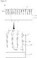
Figure 1 is a cross-sectional diagram showing a light control film manufacturing apparatus according to an example of the present invention. -
Figure 2 is a perspective diagram and a partially enlarged cross-sectional diagram of a pattern formation mold of a light control film manufacturing apparatus according to an example of the present invention. -
Figure 3 is a cross-sectional diagram and a partially enlarged diagram of a light control film according to an example of the present invention. - Advantages and features of the present invention and methods for achieving them will become apparent with reference to examples to be described below.
- The present invention is defined by the scope of the claims, and if there are separate descriptions for the meanings of terms in the specification, the term meanings will be defined by the above-described contents. Throughout the specification, the same reference numeral refers to the same component.
- The light control film manufacturing apparatus (100) of the present invention comprises a pattern formation mold (30), wherein a pattern formation structure (32) of the pattern formation mold (30) comprises a bent portion (32c), thereby being capable of reducing appearance defects of the light control film (200).
- In this regard, a light control film manufacturing apparatus (100) according to an example of the present invention will be described with reference to
Figure 1 . - First, a film supply device (10) will be described.
- The light control film manufacturing apparatus (100) according to an example of the present invention may comprise a film supply device (10) for providing a base film (210).
- The base film (210) functions as a base support layer of the light control film (200) to be described below, where details will be described below.
- The film supply device (10) winds the base film (210) in the form of a roll as one example, and the film supply device (10) rotates to release the base film (210) in the process progress direction, thereby being capable of supplying the base film (210).
- However, the shape and operation contents of the film supply device (10) are not limited to the contents posted in the above description and drawings, which will include contents that can be easily designed and changed by those skilled in the art.
- Subsequently, the light control film manufacturing apparatus (100) is positioned between the film supply device (10) and the pattern formation mold (30) to be described below, which may further comprise a coating device (20) for coating a resin layer (220') on at least one side of the supplied base film (210).
- For example, the resin layer (220') may be coated on the front surface of the base film (210) to a predetermined thickness, and the resin layer (220') may be cured by subsequent heat or light curing treatment.
- In addition, the resin layer (220') may also be coated on both sides of the base film (210), and the material of the resin layer (220') will include a range that can be easily selected by those skilled in the art.
- However, the coating device (20) is not essential, and when the resin layer is already coated on the base film (210) supplied from the film supply device (10), the coating device (20) may also be omitted.
- The light control film manufacturing apparatus (100) according to an example of the present invention may comprise a pattern formation mold (30) for applying pressure on one side of the base film (210) to form a pattern.
- Specifically, the pattern formation mold (30) may partially apply pressure to the resin layer (220') coated on the base film (210) to form a pattern.
- The pressure partially applied to the resin layer (220') may be made by the shape of the pattern formation mold (30), and the detailed structure of the pattern formation mold (30) will be described below.
- In the resin layer (220') on which the pattern is formed by the pattern formation mold (30), the patterned resin layer (220') may be cured by the curing device (40).
- The curing device (40) may use photocuring, for example, UV curing, according to curing characteristics of the resin layer (220'), or it may be thermally cured using a heat source.
- The resin layer (220') cured by the curing device (40) may become a pattern forming layer (220) in which a pattern is maintained.
- The pattern forming layer (220) formed by the curing device (40) may be separated from the pattern formation mold (30), and the pattern forming layer (220) and the base film (210) separated from the pattern formation mold (30) may be wound and stored by the collecting device (50).
- Subsequently, the structure of the pattern formation mold (30) for forming a pattern on the resin layer (220') and/or the pattern forming layer (220) will be described in detail.
- Referring back to
Figures 1 and2 , the pattern formation mold (30) may comprise a main body (31) and a pattern formation structure (32) protruding from the outer surface of the main body (31) and extending in the first direction. - The pattern formation structure (32) is composed of a plurality of structures, which may be spaced apart from each other.
- For example, the pattern formation structure (32) may be spaced apart from each other with a spaced-apart distance of about 20µm to about 70µm.
- The main body (31) may provide a basic shape of the pattern formation mold (30) and may function to be connected to the pattern formation structure (32), thereby supporting it.
- The main body (31) may have a cylindrical shape, but the shape of the main body (31) is not limited thereto, and it will include a shape that can be easily designed and changed by those skilled in the art.
- For example, the main body (31) may also have a polygonal column shape or a plate shape.
- The pattern formation structure (32) protrudes from the main body (31) to the outside and substantially functions to partially apply pressure to the resin layer (220').
- Specifically, as described above, the pattern formation structure (32) may have a structure that protrudes from the outer surface of the main body (31) and extends in the first direction.
- For example, when the main body (31) has a cylindrical shape, the pattern formation structure (32) may be formed in a circumferential direction, and when the main body (31) has a plate shape, the pattern formation structure (32) may be formed in a straight direction.
- Meanwhile, the pattern formation structure (32) comprises a bent portion (32c) formed on the outer surface, so that upon manufacturing the light control film (200), the bending of the groove portion (221) in the light control film (200) or the scratch occurrence of the groove portion (221) inner surface is reduced, whereby it is possible to reduce the appearance defects of the light control film (200).
- The bent portion (32c) of the pattern formation structure (32) may be formed on a side surface of the pattern formation structure (32). Accordingly, the side surface of the pattern formation structure (32) may form a structure that the surfaces having different inclinations meet to be bent at a predetermined angle.
- Specifically, when the pattern formation structure (32) is viewed from a cross-section perpendicular to the first direction, the cross-section of the pattern formation structure (32) may comprise a pair of first intersecting lines (32a), one ends of which are connected to the main body (31), having a first intersecting angle (θ1).
- The pair of first intersecting lines (32a) are of two-line segments, wherein the respective line segments have one ends (32a1) connected to the main body (31), which may extend to the outside of the main body (32) so that they may have a first intersecting angle (θ1) from each other.
- Each first intersecting line (32a) may have a length of about 1µm to about 5µm.
- The other ends (32a2) of the pair of first intersecting lines (32a) are not in contact with each other and are spaced apart from each other, and merely, the first intersecting angle (θ1) formed by intersecting virtual lines extending from the other ends (32a2) of the first intersecting lines (32a), respectively, may be less than about 180 degrees, and may be about 80 degrees to about 100 degrees.
- In addition, the cross-section of the pattern formation structure (32) may comprise a pair of second intersecting lines (32b) connected to the pair of first intersecting lines (32a), respectively.
- The pair of second intersecting lines (32b) extend from the other ends (32a2) of the first intersecting lines (32a), respectively, which may have a second intersecting angle (θ2) smaller than the first intersecting angle (θ1).
- Specifically, the second intersecting lines (32b) are of two-line segments, wherein the respective one ends (32b1) of the second intersecting lines (32b) are connected to the other ends (32a2) of the first intersecting lines (32a), which may extend in the outside direction of the main body (31) so that they may have a second intersecting angle (θ2) from each other.
- The other ends (32b2) of the pair of second intersecting lines (32b) may be spaced apart from each other without being in contact with each other or may be directly connected by an intersecting point.
- When the other ends (32b2) of the second intersecting lines (32b) are spaced apart from each other without contacting each other, the other ends (32b2) may be connected by a connecting line (32b3).
- The second intersecting angle (θ2) is formed by intersecting real or virtual lines extending from the other ends (32b2) of the second intersection lines (32b), similar to the first intersecting angle (θ1), which may be smaller than the first intersecting angle (θ1).
- Accordingly, a bent portion (32c), in which the side surface of the pattern formation structure (32) is bent, is formed at a portion where the first intersecting line (32a) and the second intersecting line (32b) meet.
- Furthermore, since the second intersecting angle (θ2) is greater than the first intersecting angle (θ1), the pattern formation structure (32) may protrude more sharply as it moves away from the main body (32) based on the bent portion (32c).
- As described above, the pattern formation structure (32) comprises a bent portion (32c), so that upon manufacturing the light control film (200), the bending of the groove portion (221) in the light control film (200) or the scratch occurrence of the groove portion (221) inner surface is reduced, whereby it is possible to reduce the appearance defects of the light control film (200).
- Specifically, the pattern formation structure (32) may be formed by partially cutting the surface of the pattern formation mold (30).
- Accordingly, a significant amount of impact or force may be continuously applied to the pattern formation structure (32) during the process of forming the plurality of pattern formation structures (32) through surface cutting. As a result, the pattern formation structure protruding in a narrow area is bent to one side or the pattern formation structure is formed in an area larger than the design area, so that there may be a problem that the viewing angle of the light control film is asymmetrical compared to the design or the transmittance is lowered.
- However, in the pattern formation structure (32) according to an example of the present invention, a portion adjacent to the main body (31) based on the bent portion (32c) is connected to the main body (31) with a relatively large area, so that effectively, the structure of the bent portion (32c) upper end portion in the pattern formation structure (32) may be stably maintained.
- Accordingly, even if significant impact or force is applied to the protruding pointedshaped pattern formation structure (32) in the process of forming the pattern formation structure (32), the deformation of the pattern formation structure (32) may be reduced and the shape defects of the groove portion (221) formed in the light control film (200) may also be reduced.
- Furthermore, the pattern formation structure (32) according to an example of the present invention comprises the bent portion (32c), whereby it is possible to reduce the occurrence of scratches on the inner surface of the pattern formation structure (32) or the groove portion (221).
- Specifically, as described above, in the process of forming the pattern formation structure (32), a large amount of chips may be generated when the surface of the pattern formation mold (30) is cut.
- These chips may break in the middle depending on the cutting shape, and may form scratches on the cutting surface by the broken chip portion.
- Accordingly, the pattern formation structure (32) according to an example of the present invention comprises the bent portion (32c) and thus the area of the portion adjacent to the main body (31) is formed to be relatively large, so that chips generated from the side or bottom surface to be cut are not easily broken, and as a result, it is possible to reduce the occurrence of scratches by chips on the cutting surface.
- Additionally, the first intersecting angle (θ1) may be about 80 degrees to about 100 degrees, and the pattern formation structure (32) according to an example of the present invention controls the first intersecting angle (θ1) as above, whereby chip discharge may be performed stably, and it is possible to minimize surface scratches or warpage of the pattern formation structure (32).
- Moreover, the pattern formation structure (32) according to an example of the present invention may also reduce shape defects of the groove portion (221) that may occur in the process of separating the cured pattern forming layer (220) or the resin layer (220') to be cured from the pattern formation mold (30).
- Specifically, the pattern formation structure (32) and the pattern (groove portion (221)) of the cured pattern forming layer (220) or the resin layer (220') to be cured matching the same are separated.
- In this process, the portion of the pattern formation structure (32) adjacent to the main body (31) based on the bent portion (32c) has a relatively large area, so that the upper side opening portion of the groove portion (221) separated from the pattern formation structure (32) is formed in an expanded shape, and as a result, the easiness of separation between the pattern forming layer (220) or the resin layer (220') and the pattern formation structure (32) is improved, whereby it is possible to reduce the shape deformation or the inner surface damage of the groove portion (221).
- Subsequently, the light control film (200) according to an example of the present invention will be described.
- The light control film (200) may be manufactured by the light control film manufacturing apparatus (100).
- Referring to
Figure 3 , the light control film (200) may comprise a base film (210). - As described above, the base film (210) may function as a base support layer of the light control film (200).
- The base film (210) may comprise PET, PC, TAC, and the like, but the constituent material of the base film (210) is not limited to the above description, which will include a range that can be easily selected by those skilled in the art.
- A pattern forming layer (220) may be disposed on one side of the base film (210), and an adhesive primer layer may be optionally added between the base film (210) and the pattern forming layer (220) for stability of attachment of the pattern forming layer (220).
- Furthermore, a coating layer such as an antireflection layer may also be added on the other side of the base film (210) opposite to the pattern forming layer (220).
- The pattern forming layer (220) is a portion through which light passes, which may comprise a groove portion (221) formed on one side opposite to the base film (210) and extending in the first direction.
- The pattern forming layer (220) may comprise a cured product of a curable resin, and for example, it may comprise a cured product of a UV-curable resin.
- The groove portion (221) may have a structure corresponding to the shape of the pattern formation structure (32) of the above-described pattern formation mold (30) as a shape concave into the pattern forming layer (220).
- Accordingly, the descriptions of the first intersecting lines (32a) and the second intersecting lines (32b) of the pattern formation structure (32) can be applied to the first intersecting lines (221a) and the second intersecting lines (221b) of the groove portion (221) as such.
- In addition, the groove portion (221) is formed of a plurality of grooves, which may be spaced apart from each other.
- The cross-section of the groove portion (221) perpendicular to the first direction may comprise a pair of first intersecting lines (221a), one ends (221a1) of which are connected to one side of the pattern forming layer (220), having a first intersecting angle (θ1).
- Unlike the pattern formation structure (32), an opening portion is formed between one ends (221a1) of the first intersecting lines (221a), which may have a shape that the area of the opening portion is narrowed toward the inside of the pattern forming layer (220).
- In addition, the cross-section of the groove portion (221) may comprise a pair of second intersecting lines (221b) extending from the other ends (221a2) of the first intersecting lines (221a), respectively and having a second intersecting angle (θ2) smaller than the first intersecting angle (θ1).
- Accordingly, the bent portion (221c) may also be formed on the inner surface of the groove portion (221).
- A light absorbing material (222) may be disposed inside the groove portion (221). Specifically, the light absorbing material (222) may be disposed in such a way that the light absorbing material (222) is filled into the formed groove portion (221).
- The light absorbing material (222) may be a material capable of absorbing or blocking light in at least a portion of the visible spectrum.
- For example, the light absorbing material (222) may include a black colorant such as carbon black or black beads, and the composition and concentration of the light absorbing material (222) may be adjusted in consideration of light absorption and blocking performance.
- The light absorbing material (222) may be filled up to the other ends (221a2) of the first intersection lines (221a) of the groove portion (221).
- As described above, in the light control film (200) according to an example of the present invention, the portion of the groove portion (221) close to the front surface based on the bent portion (221c) is formed in an expanded shape, and the light absorbing material (222) is filled up to the other ends (221a2) of the first intersecting lines (221a) in the groove portion (221), whereby it is possible to effectively reduce the white line phenomenon that occurs as the light absorbing material (222) is not sufficiently filled due to the foreign material being caught in the narrow opening.
- Furthermore, the light absorbing material (222) is filled up to the other ends (221a2) of the first intersection lines (221a) of the groove portion (221), whereby it is possible to prevent the aperture ratio from being excessively decreased.
- Specifically, when the light absorbing material (222) is filled up to the one ends (221a1) of the first intersecting lines (221a), the aperture ratio may excessively decrease because the light incidence area is reduced by the light absorbing material (222) on one side. Accordingly, in an example of the present invention, the filling position of the light absorbing material (222) may be controlled by the other ends (221a2) of the first intersecting lines (221a).
- Subsequently, referring to Tables 1 and 2, characteristic changes according to the length of the first intersecting line (221a) and the first intersecting angle in the light control film (200) according to an example of the present invention will be described.
[Table 1] Fist intersecting angle (°) Scratch and warpage occurrence 20° Occurrence 40° Occurrence 60° Occurrence 80° No occurrence 100° No occurrence 120° Occurrence 140° Occurrence 160° Occurrence - In Table 1 above, the occurrence of scratches and warpage according to the change of the first intersecting angle in the pattern formation mold (30) and the groove portion (221) is visually observed and recorded.
- Referring to Table 1 above, the light control film (200) of the present invention maintains the first intersecting angle between 80° and 100°, whereby it is possible to effectively prevent the occurrence of scratches and warpage.
[Table 2] Length of first intersecting line (221a) [µm] White line occurrence Whether or not the light absorbing material remains in the portion of the first intersecting line 1 Occurrence No occurrence 2 No occurrence No occurrence 3 No occurrence No occurrence 4 No occurrence No occurrence 5 No occurrence No occurrence 6 No occurrence Occurrence 7 No occurrence Occurrence 8 No occurrence Occurrence - In Table 2 above, the occurrence of white lines according to the length change of the first intersecting line (221a) in the groove portion (221) and the remains of the light absorbing material in the first intersecting line portion are visually observed and recorded.
- Referring to Table 2 above, when the light control film (200) of the present invention controls the length of the first intersecting line (221a) to be 2µm to 5µm, the white line phenomenon is prevented and simultaneously it is prevented that the light absorbing material (222) remains in the first intersecting line portion, whereby it is possible to prevent the aperture ratio from decreasing.
- In this specification, the first intersecting line portion means a space between the other end (221a2) of the first intersecting line and one end (221a1) of the first intersecting line.
- Although the examples of the present invention have been illustrated and described as above, the present invention is not limited to the above-described specific examples, and without departing from the gist of the present invention as claimed in the claims, various modifications may be performed by those having ordinary knowledge in the technical field to which the relevant invention pertains, and these modifications should not be individually understood from the technical spirit or perspective of the present invention.
Claims (15)
- An apparatus for manufacturing a light control film, the apparatus comprising:a film supply device configured to supply a base film; anda pattern formation mold configured to form a pattern by applying pressure onto one side of the base film,wherein the pattern formation mold comprises a main body and a pattern formation structure protruding from an outer surface of the main body and extending in a first direction,wherein a cross-section perpendicular to the first direction of the pattern formation structure comprises a pair of first intersecting lines and a pair of second intersecting lines,wherein each of the first intersecting lines has one end connected to the main body and the other end, and the first intersecting lines have a first intersecting angle formed by intersecting virtual lines each of which extended from said the other end of the each of the first intersecting lines, andwherein each of the second intersecting lines extends from said the other end of the each of the pair of first intersecting lines such that the pair of second intersecting lines forms a second intersecting angle smaller than the first intersecting angle.
- The apparatus according to claim 1, wherein the main body has a cylindrical shape or a plate shape.
- The apparatus according to claim 1, wherein the first intersecting lines and the second intersecting lines extend in a direction away from the main body.
- The apparatus according to claim 1, wherein the pattern formation mold comprises a plurality of the pattern formation structures, and the plurality of the pattern formation structures is spaced apart from each other.
- The apparatus according to claim 1, wherein each of the second intersecting lines has one end and the other end, wherein said the other ends of the second intersecting lines are connected by an intersecting point or a connecting line.
- The apparatus according to claim 1, wherein each of the first intersecting lines has a length of 2µm to 5µm.
- The apparatus according to claim 1, wherein the first intersecting angle is 80° to 100°.
- The apparatus according to claim 4, wherein a distance between the pattern formation structures spaced apart from each other is from 20µm to 70µm.
- The apparatus according to claim 1, further comprising a coating device configured to coat a curable resin layer on at least one side of the base film supplied by the film supply device, wherein the coating device is positioned between the film supply device and the pattern formation mold.
- The apparatus according to claim 9, wherein the pattern formation structure is configured to apply pressure to the curable resin layer to form a pattern on the curable resin layer.
- Alight control film comprising:a base film;a pattern forming layer disposed on the base film and comprising a groove portion formed on one surface opposite to a surface adjacent to the base film and extending in the first direction; anda light absorbing material disposed in the groove portion,wherein a cross-section perpendicular to the first direction of the groove portion comprises:a pair of first intersecting lines, one ends of which are connected to the one surface of the pattern forming layer, and having a first intersecting angle; anda pair of second intersecting lines extending from the other ends of the pair of first intersecting lines respectively and having a second intersecting angle smaller than the first intersecting angle, andwherein the first intersecting angle is 80 degrees to 100 degrees.
- The light control film according to claim 11, wherein each of the pair of first intersecting line has a length of 1µm to 5µm.
- The light control film according to claim 11, wherein the pattern forming layer comprises a plurality of the groove portions and the groove portions are spaced apart from each other.
- The light control film according to claim 13, wherein a distance between the groove portions spaced apart from each other is from 20µm to 70µm.
- The light control film according to claim 11, wherein the light absorbing material is filled to said the other ends of the first intersecting lines in the groove portion.
Applications Claiming Priority (1)
| Application Number | Priority Date | Filing Date | Title |
|---|---|---|---|
| PCT/KR2020/000641 WO2021145469A1 (en) | 2020-01-14 | 2020-01-14 | Light control film manufacturing apparatus and light control film manufactured by same |
Publications (3)
| Publication Number | Publication Date |
|---|---|
| EP4091804A1 true EP4091804A1 (en) | 2022-11-23 |
| EP4091804A4 EP4091804A4 (en) | 2023-01-25 |
| EP4091804B1 EP4091804B1 (en) | 2025-12-03 |
Family
ID=76864665
Family Applications (1)
| Application Number | Title | Priority Date | Filing Date |
|---|---|---|---|
| EP20913130.9A Active EP4091804B1 (en) | 2020-01-14 | 2020-01-14 | Light control film manufacturing apparatus and light control film manufactured by same |
Country Status (6)
| Country | Link |
|---|---|
| US (1) | US12539681B2 (en) |
| EP (1) | EP4091804B1 (en) |
| JP (1) | JP7451018B2 (en) |
| KR (1) | KR102804731B1 (en) |
| CN (1) | CN114981073B (en) |
| WO (1) | WO2021145469A1 (en) |
Cited By (1)
| Publication number | Priority date | Publication date | Assignee | Title |
|---|---|---|---|---|
| EP4642199A4 (en) * | 2022-12-21 | 2026-03-25 | Lg Chemical Ltd | LIGHT CONTROL FILM |
Families Citing this family (2)
| Publication number | Priority date | Publication date | Assignee | Title |
|---|---|---|---|---|
| CN120457804A (en) | 2022-12-21 | 2025-08-08 | 株式会社Lg化学 | Light control films |
| KR20240099097A (en) | 2022-12-21 | 2024-06-28 | 주식회사 엘지화학 | Light Control Film |
Family Cites Families (21)
| Publication number | Priority date | Publication date | Assignee | Title |
|---|---|---|---|---|
| JPS5434245B1 (en) * | 1971-05-11 | 1979-10-25 | ||
| JP2005150333A (en) * | 2003-11-14 | 2005-06-09 | Sony Corp | Manufacturing method of semiconductor device |
| JP4788314B2 (en) * | 2005-11-30 | 2011-10-05 | 大日本印刷株式会社 | Light diffusion sheet, transmissive screen, rear projection display device, and liquid crystal display device |
| JP2008242232A (en) | 2007-03-28 | 2008-10-09 | Mitsui Chemicals Inc | Viewing angle control film and optical filter for display using same |
| KR101597014B1 (en) * | 2009-02-26 | 2016-02-24 | 다이니폰 인사츠 가부시키가이샤 | Mold for forming optical sheet, and method for manufacturing mold |
| JP5434245B2 (en) | 2009-05-11 | 2014-03-05 | 大日本印刷株式会社 | Light control sheet and building |
| JP5573394B2 (en) | 2009-07-06 | 2014-08-20 | 大日本印刷株式会社 | Optical sheet manufacturing method, optical sheet, and image display device |
| TWI443011B (en) | 2011-07-29 | 2014-07-01 | Chi Mei Corp | Duplex microstructure optical plate forming apparatus and manufacturing method thereof |
| JP2013051149A (en) * | 2011-08-31 | 2013-03-14 | Dainippon Printing Co Ltd | Light guide plate, surface light source device and display device |
| JP5821519B2 (en) | 2011-10-20 | 2015-11-24 | 大日本印刷株式会社 | Roll mold manufacturing method and optical sheet manufacturing method |
| JP2013178469A (en) * | 2012-02-03 | 2013-09-09 | Nlt Technologies Ltd | Optical element |
| JP5994325B2 (en) | 2012-03-27 | 2016-09-21 | 大日本印刷株式会社 | Optical sheet, display device including the same, and method for manufacturing optical sheet |
| KR101353433B1 (en) | 2012-04-27 | 2014-01-21 | 주식회사 퓨어메이트 | Production apparatus for viewing angle control film, manufacturing process for viewing angle control film and viewing angle control film manufactured by using the same |
| KR101979273B1 (en) | 2012-07-03 | 2019-05-16 | 엘지전자 주식회사 | Light control film and method for manufacturing the same, and display apparatus |
| KR101596243B1 (en) | 2014-05-16 | 2016-02-22 | 주식회사 비에프지 | Manufacturing method for privacy securing film and manufacturing apparatus for the same |
| KR20170094697A (en) | 2016-02-11 | 2017-08-21 | 한국산업기술대학교산학협력단 | Method for making privacy film |
| JP2017205224A (en) * | 2016-05-17 | 2017-11-24 | 富士フイルム株式会社 | Mold manufacturing method |
| JP6588864B2 (en) * | 2016-05-23 | 2019-10-09 | 富士フイルム株式会社 | Method for producing transdermal absorption sheet |
| JP7047417B2 (en) * | 2018-01-31 | 2022-04-05 | 大日本印刷株式会社 | Lens sheet unit, image pickup module, image pickup device |
| KR102501097B1 (en) | 2018-06-21 | 2023-02-16 | 삼성전자주식회사 | Semiconductor device and method for fabricating the semiconductor device |
| KR102140488B1 (en) * | 2018-07-04 | 2020-08-03 | 신화인터텍 주식회사 | Functional optical sheet and method of the same |
-
2020
- 2020-01-14 WO PCT/KR2020/000641 patent/WO2021145469A1/en not_active Ceased
- 2020-01-14 JP JP2022542998A patent/JP7451018B2/en active Active
- 2020-01-14 KR KR1020227024228A patent/KR102804731B1/en active Active
- 2020-01-14 US US17/792,681 patent/US12539681B2/en active Active
- 2020-01-14 CN CN202080093081.8A patent/CN114981073B/en active Active
- 2020-01-14 EP EP20913130.9A patent/EP4091804B1/en active Active
Cited By (1)
| Publication number | Priority date | Publication date | Assignee | Title |
|---|---|---|---|---|
| EP4642199A4 (en) * | 2022-12-21 | 2026-03-25 | Lg Chemical Ltd | LIGHT CONTROL FILM |
Also Published As
| Publication number | Publication date |
|---|---|
| EP4091804B1 (en) | 2025-12-03 |
| KR20220119642A (en) | 2022-08-30 |
| JP2023510559A (en) | 2023-03-14 |
| JP7451018B2 (en) | 2024-03-18 |
| WO2021145469A1 (en) | 2021-07-22 |
| CN114981073A (en) | 2022-08-30 |
| US20230047995A1 (en) | 2023-02-16 |
| US12539681B2 (en) | 2026-02-03 |
| KR102804731B1 (en) | 2025-05-12 |
| EP4091804A4 (en) | 2023-01-25 |
| CN114981073B (en) | 2024-09-17 |
Similar Documents
| Publication | Publication Date | Title |
|---|---|---|
| EP4091804B1 (en) | Light control film manufacturing apparatus and light control film manufactured by same | |
| US7542207B2 (en) | Antiglare and antireflection film polarizing plate and display device | |
| KR101130629B1 (en) | Antiglare film, method of producing the same, anti-reflection film, polarizing plate, and image display device | |
| US6830348B2 (en) | Antiglare and antireflection film, polarizer, and image display device | |
| US6778240B2 (en) | Anti-glare and anti-reflection film, polarizing plate, and image display device | |
| US10792955B2 (en) | Plate with printed layer, manufacturing method thereof, and display device | |
| KR20040000322A (en) | Method of producing glare-proof antireflection film | |
| WO2006028027A1 (en) | Method of producing optical film and anti-reflection film, optical film, anti-reflection film, polarizing plate and image display device comprising same | |
| KR100737229B1 (en) | Matte high transmittance film, polarizing plate and liquid crystal display using the same | |
| JP4242595B2 (en) | Antiglare antireflection film, polarizing plate and display device | |
| JP2003222704A (en) | Reflection preventive film, polarizing plate and display device | |
| US20130004726A1 (en) | Light Guide Plate, and Method and Apparatus of Manufacturing Same | |
| JP2006072315A (en) | Polarizing plate with antireflection ability, method for producing the same, and image display device using the same | |
| KR20140004505A (en) | Light control film and method for manufacturing the same, and display apparatus | |
| JP2006096861A (en) | Coating composition, optically functional layer, antireflection film, polarization plate and image display device | |
| WO2005114271A1 (en) | Polarization plate with antireflection function, process for producing the same, and image display unit utilizing the same | |
| JP2006334561A (en) | Drying method of coating film | |
| JP4538482B2 (en) | Antiglare antireflection film, polarizing plate and display device | |
| JP2012185290A (en) | Method for manufacturing anti-glare film | |
| JPH11337705A (en) | Light-absorbing plastic film structure having antireflection film | |
| CN109471327A (en) | A kind of S-shaped anti-light curtain and preparation method thereof | |
| CN106199773A (en) | A kind of optical film stack of high mechanical stability and preparation method thereof | |
| CN115542440B (en) | A double-layer composite light-diffusing film, its manufacturing system, and manufacturing method | |
| JP2005208606A (en) | Polarizing plate and liquid crystal display apparatus | |
| JP2007075794A (en) | Coating film curing apparatus and method |
Legal Events
| Date | Code | Title | Description |
|---|---|---|---|
| STAA | Information on the status of an ep patent application or granted ep patent |
Free format text: STATUS: THE INTERNATIONAL PUBLICATION HAS BEEN MADE |
|
| PUAI | Public reference made under article 153(3) epc to a published international application that has entered the european phase |
Free format text: ORIGINAL CODE: 0009012 |
|
| STAA | Information on the status of an ep patent application or granted ep patent |
Free format text: STATUS: REQUEST FOR EXAMINATION WAS MADE |
|
| 17P | Request for examination filed |
Effective date: 20220713 |
|
| AK | Designated contracting states |
Kind code of ref document: A1 Designated state(s): AL AT BE BG CH CY CZ DE DK EE ES FI FR GB GR HR HU IE IS IT LI LT LU LV MC MK MT NL NO PL PT RO RS SE SI SK SM TR |
|
| A4 | Supplementary search report drawn up and despatched |
Effective date: 20221222 |
|
| RIC1 | Information provided on ipc code assigned before grant |
Ipc: G02B 5/22 20060101ALI20221216BHEP Ipc: B29C 59/00 20060101ALI20221216BHEP Ipc: B29D 11/00 20060101AFI20221216BHEP |
|
| DAV | Request for validation of the european patent (deleted) | ||
| DAX | Request for extension of the european patent (deleted) | ||
| STAA | Information on the status of an ep patent application or granted ep patent |
Free format text: STATUS: EXAMINATION IS IN PROGRESS |
|
| 17Q | First examination report despatched |
Effective date: 20250113 |
|
| GRAP | Despatch of communication of intention to grant a patent |
Free format text: ORIGINAL CODE: EPIDOSNIGR1 |
|
| STAA | Information on the status of an ep patent application or granted ep patent |
Free format text: STATUS: GRANT OF PATENT IS INTENDED |
|
| INTG | Intention to grant announced |
Effective date: 20250822 |
|
| GRAS | Grant fee paid |
Free format text: ORIGINAL CODE: EPIDOSNIGR3 |
|
| GRAA | (expected) grant |
Free format text: ORIGINAL CODE: 0009210 |
|
| STAA | Information on the status of an ep patent application or granted ep patent |
Free format text: STATUS: THE PATENT HAS BEEN GRANTED |
|
| AK | Designated contracting states |
Kind code of ref document: B1 Designated state(s): AL AT BE BG CH CY CZ DE DK EE ES FI FR GB GR HR HU IE IS IT LI LT LU LV MC MK MT NL NO PL PT RO RS SE SI SK SM TR |
|
| REG | Reference to a national code |
Ref country code: CH Ref legal event code: F10 Free format text: ST27 STATUS EVENT CODE: U-0-0-F10-F00 (AS PROVIDED BY THE NATIONAL OFFICE) Effective date: 20251203 Ref country code: GB Ref legal event code: FG4D |
|
| REG | Reference to a national code |
Ref country code: DE Ref legal event code: R096 Ref document number: 602020063460 Country of ref document: DE |
|
| REG | Reference to a national code |
Ref country code: IE Ref legal event code: FG4D |
|
| REG | Reference to a national code |
Ref country code: NL Ref legal event code: MP Effective date: 20251203 |
|
| PG25 | Lapsed in a contracting state [announced via postgrant information from national office to epo] |
Ref country code: ES Free format text: LAPSE BECAUSE OF FAILURE TO SUBMIT A TRANSLATION OF THE DESCRIPTION OR TO PAY THE FEE WITHIN THE PRESCRIBED TIME-LIMIT Effective date: 20251203 |
|
| REG | Reference to a national code |
Ref country code: LT Ref legal event code: MG9D |
|
| PG25 | Lapsed in a contracting state [announced via postgrant information from national office to epo] |
Ref country code: NO Free format text: LAPSE BECAUSE OF FAILURE TO SUBMIT A TRANSLATION OF THE DESCRIPTION OR TO PAY THE FEE WITHIN THE PRESCRIBED TIME-LIMIT Effective date: 20260303 |
|
| PGFP | Annual fee paid to national office [announced via postgrant information from national office to epo] |
Ref country code: DE Payment date: 20260205 Year of fee payment: 7 |
|
| PG25 | Lapsed in a contracting state [announced via postgrant information from national office to epo] |
Ref country code: FI Free format text: LAPSE BECAUSE OF FAILURE TO SUBMIT A TRANSLATION OF THE DESCRIPTION OR TO PAY THE FEE WITHIN THE PRESCRIBED TIME-LIMIT Effective date: 20251203 Ref country code: HR Free format text: LAPSE BECAUSE OF FAILURE TO SUBMIT A TRANSLATION OF THE DESCRIPTION OR TO PAY THE FEE WITHIN THE PRESCRIBED TIME-LIMIT Effective date: 20251203 |
|
| PG25 | Lapsed in a contracting state [announced via postgrant information from national office to epo] |
Ref country code: RS Free format text: LAPSE BECAUSE OF FAILURE TO SUBMIT A TRANSLATION OF THE DESCRIPTION OR TO PAY THE FEE WITHIN THE PRESCRIBED TIME-LIMIT Effective date: 20260303 |
|
| PG25 | Lapsed in a contracting state [announced via postgrant information from national office to epo] |
Ref country code: PL Free format text: LAPSE BECAUSE OF FAILURE TO SUBMIT A TRANSLATION OF THE DESCRIPTION OR TO PAY THE FEE WITHIN THE PRESCRIBED TIME-LIMIT Effective date: 20251203 |
|
| PG25 | Lapsed in a contracting state [announced via postgrant information from national office to epo] |
Ref country code: LV Free format text: LAPSE BECAUSE OF FAILURE TO SUBMIT A TRANSLATION OF THE DESCRIPTION OR TO PAY THE FEE WITHIN THE PRESCRIBED TIME-LIMIT Effective date: 20251203 |
|
| PG25 | Lapsed in a contracting state [announced via postgrant information from national office to epo] |
Ref country code: BG Free format text: LAPSE BECAUSE OF FAILURE TO SUBMIT A TRANSLATION OF THE DESCRIPTION OR TO PAY THE FEE WITHIN THE PRESCRIBED TIME-LIMIT Effective date: 20251203 |