EP4091389B1 - Wireless in-vehicle networking enhanced interference detection via external sensors - Google Patents
Wireless in-vehicle networking enhanced interference detection via external sensors Download PDFInfo
- Publication number
- EP4091389B1 EP4091389B1 EP20828228.5A EP20828228A EP4091389B1 EP 4091389 B1 EP4091389 B1 EP 4091389B1 EP 20828228 A EP20828228 A EP 20828228A EP 4091389 B1 EP4091389 B1 EP 4091389B1
- Authority
- EP
- European Patent Office
- Prior art keywords
- vehicle
- vehicles
- location
- wireless
- interference
- Prior art date
- Legal status (The legal status is an assumption and is not a legal conclusion. Google has not performed a legal analysis and makes no representation as to the accuracy of the status listed.)
- Active
Links
Images



Classifications
-
- H—ELECTRICITY
- H04—ELECTRIC COMMUNICATION TECHNIQUE
- H04W—WIRELESS COMMUNICATION NETWORKS
- H04W4/00—Services specially adapted for wireless communication networks; Facilities therefor
- H04W4/30—Services specially adapted for particular environments, situations or purposes
- H04W4/40—Services specially adapted for particular environments, situations or purposes for vehicles, e.g. vehicle-to-pedestrians [V2P]
- H04W4/46—Services specially adapted for particular environments, situations or purposes for vehicles, e.g. vehicle-to-pedestrians [V2P] for vehicle-to-vehicle communication [V2V]
-
- H—ELECTRICITY
- H04—ELECTRIC COMMUNICATION TECHNIQUE
- H04B—TRANSMISSION
- H04B17/00—Monitoring; Testing
- H04B17/20—Monitoring; Testing of receivers
- H04B17/27—Monitoring; Testing of receivers for locating or positioning the transmitter
-
- H—ELECTRICITY
- H04—ELECTRIC COMMUNICATION TECHNIQUE
- H04W—WIRELESS COMMUNICATION NETWORKS
- H04W4/00—Services specially adapted for wireless communication networks; Facilities therefor
- H04W4/30—Services specially adapted for particular environments, situations or purposes
- H04W4/40—Services specially adapted for particular environments, situations or purposes for vehicles, e.g. vehicle-to-pedestrians [V2P]
- H04W4/48—Services specially adapted for particular environments, situations or purposes for vehicles, e.g. vehicle-to-pedestrians [V2P] for in-vehicle communication
-
- B—PERFORMING OPERATIONS; TRANSPORTING
- B60—VEHICLES IN GENERAL
- B60W—CONJOINT CONTROL OF VEHICLE SUB-UNITS OF DIFFERENT TYPE OR DIFFERENT FUNCTION; CONTROL SYSTEMS SPECIALLY ADAPTED FOR HYBRID VEHICLES; ROAD VEHICLE DRIVE CONTROL SYSTEMS FOR PURPOSES NOT RELATED TO THE CONTROL OF A PARTICULAR SUB-UNIT
- B60W30/00—Purposes of road vehicle drive control systems not related to the control of a particular sub-unit, e.g. of systems using conjoint control of vehicle sub-units
- B60W30/08—Active safety systems predicting or avoiding probable or impending collision or attempting to minimise its consequences
-
- H—ELECTRICITY
- H04—ELECTRIC COMMUNICATION TECHNIQUE
- H04B—TRANSMISSION
- H04B17/00—Monitoring; Testing
- H04B17/30—Monitoring; Testing of propagation channels
- H04B17/309—Measuring or estimating channel quality parameters
- H04B17/345—Interference values
-
- H—ELECTRICITY
- H04—ELECTRIC COMMUNICATION TECHNIQUE
- H04W—WIRELESS COMMUNICATION NETWORKS
- H04W4/00—Services specially adapted for wireless communication networks; Facilities therefor
- H04W4/02—Services making use of location information
- H04W4/023—Services making use of location information using mutual or relative location information between multiple location based services [LBS] targets or of distance thresholds
-
- H—ELECTRICITY
- H04—ELECTRIC COMMUNICATION TECHNIQUE
- H04W—WIRELESS COMMUNICATION NETWORKS
- H04W4/00—Services specially adapted for wireless communication networks; Facilities therefor
- H04W4/30—Services specially adapted for particular environments, situations or purposes
- H04W4/38—Services specially adapted for particular environments, situations or purposes for collecting sensor information
-
- H—ELECTRICITY
- H04—ELECTRIC COMMUNICATION TECHNIQUE
- H04W—WIRELESS COMMUNICATION NETWORKS
- H04W52/00—Power management, e.g. Transmission Power Control [TPC] or power classes
- H04W52/04—Transmission power control [TPC]
- H04W52/38—TPC being performed in particular situations
- H04W52/44—TPC being performed in particular situations in connection with interruption of transmission
-
- H—ELECTRICITY
- H04—ELECTRIC COMMUNICATION TECHNIQUE
- H04W—WIRELESS COMMUNICATION NETWORKS
- H04W72/00—Local resource management
- H04W72/50—Allocation or scheduling criteria for wireless resources
- H04W72/54—Allocation or scheduling criteria for wireless resources based on quality criteria
- H04W72/541—Allocation or scheduling criteria for wireless resources based on quality criteria using the level of interference
-
- B—PERFORMING OPERATIONS; TRANSPORTING
- B60—VEHICLES IN GENERAL
- B60W—CONJOINT CONTROL OF VEHICLE SUB-UNITS OF DIFFERENT TYPE OR DIFFERENT FUNCTION; CONTROL SYSTEMS SPECIALLY ADAPTED FOR HYBRID VEHICLES; ROAD VEHICLE DRIVE CONTROL SYSTEMS FOR PURPOSES NOT RELATED TO THE CONTROL OF A PARTICULAR SUB-UNIT
- B60W2554/00—Input parameters relating to objects
- B60W2554/40—Dynamic objects, e.g. animals, windblown objects
- B60W2554/404—Characteristics
- B60W2554/4041—Position
-
- B—PERFORMING OPERATIONS; TRANSPORTING
- B60—VEHICLES IN GENERAL
- B60W—CONJOINT CONTROL OF VEHICLE SUB-UNITS OF DIFFERENT TYPE OR DIFFERENT FUNCTION; CONTROL SYSTEMS SPECIALLY ADAPTED FOR HYBRID VEHICLES; ROAD VEHICLE DRIVE CONTROL SYSTEMS FOR PURPOSES NOT RELATED TO THE CONTROL OF A PARTICULAR SUB-UNIT
- B60W2556/00—Input parameters relating to data
- B60W2556/45—External transmission of data to or from the vehicle
- B60W2556/65—Data transmitted between vehicles
-
- B—PERFORMING OPERATIONS; TRANSPORTING
- B60—VEHICLES IN GENERAL
- B60W—CONJOINT CONTROL OF VEHICLE SUB-UNITS OF DIFFERENT TYPE OR DIFFERENT FUNCTION; CONTROL SYSTEMS SPECIALLY ADAPTED FOR HYBRID VEHICLES; ROAD VEHICLE DRIVE CONTROL SYSTEMS FOR PURPOSES NOT RELATED TO THE CONTROL OF A PARTICULAR SUB-UNIT
- B60W2710/00—Output or target parameters relating to a particular sub-units
- B60W2710/30—Auxiliary equipments
-
- H—ELECTRICITY
- H04—ELECTRIC COMMUNICATION TECHNIQUE
- H04L—TRANSMISSION OF DIGITAL INFORMATION, e.g. TELEGRAPHIC COMMUNICATION
- H04L67/00—Network arrangements or protocols for supporting network services or applications
- H04L67/01—Protocols
- H04L67/12—Protocols specially adapted for proprietary or special-purpose networking environments, e.g. medical networks, sensor networks, networks in vehicles or remote metering networks
-
- H—ELECTRICITY
- H04—ELECTRIC COMMUNICATION TECHNIQUE
- H04W—WIRELESS COMMUNICATION NETWORKS
- H04W64/00—Locating users or terminals or network equipment for network management purposes, e.g. mobility management
- H04W64/003—Locating users or terminals or network equipment for network management purposes, e.g. mobility management locating network equipment
-
- H—ELECTRICITY
- H04—ELECTRIC COMMUNICATION TECHNIQUE
- H04W—WIRELESS COMMUNICATION NETWORKS
- H04W64/00—Locating users or terminals or network equipment for network management purposes, e.g. mobility management
- H04W64/006—Locating users or terminals or network equipment for network management purposes, e.g. mobility management with additional information processing, e.g. for direction or speed determination
-
- H—ELECTRICITY
- H04—ELECTRIC COMMUNICATION TECHNIQUE
- H04W—WIRELESS COMMUNICATION NETWORKS
- H04W72/00—Local resource management
- H04W72/02—Selection of wireless resources by user or terminal
-
- H—ELECTRICITY
- H04—ELECTRIC COMMUNICATION TECHNIQUE
- H04W—WIRELESS COMMUNICATION NETWORKS
- H04W72/00—Local resource management
- H04W72/04—Wireless resource allocation
- H04W72/044—Wireless resource allocation based on the type of the allocated resource
- H04W72/0453—Resources in frequency domain, e.g. a carrier in FDMA
-
- H—ELECTRICITY
- H04—ELECTRIC COMMUNICATION TECHNIQUE
- H04W—WIRELESS COMMUNICATION NETWORKS
- H04W84/00—Network topologies
- H04W84/005—Moving wireless networks
-
- Y—GENERAL TAGGING OF NEW TECHNOLOGICAL DEVELOPMENTS; GENERAL TAGGING OF CROSS-SECTIONAL TECHNOLOGIES SPANNING OVER SEVERAL SECTIONS OF THE IPC; TECHNICAL SUBJECTS COVERED BY FORMER USPC CROSS-REFERENCE ART COLLECTIONS [XRACs] AND DIGESTS
- Y02—TECHNOLOGIES OR APPLICATIONS FOR MITIGATION OR ADAPTATION AGAINST CLIMATE CHANGE
- Y02D—CLIMATE CHANGE MITIGATION TECHNOLOGIES IN INFORMATION AND COMMUNICATION TECHNOLOGIES [ICT], I.E. INFORMATION AND COMMUNICATION TECHNOLOGIES AIMING AT THE REDUCTION OF THEIR OWN ENERGY USE
- Y02D30/00—Reducing energy consumption in communication networks
- Y02D30/70—Reducing energy consumption in communication networks in wireless communication networks
Definitions
- Wireless interference sources may include wireless nodes within a vehicle, and wireless signals external to a vehicle, the latter including in-vehicle wireless networks from adjacent vehicles. Successfully detecting and managing external interference sources are a prerequisite for realizing effective, reliable in-vehicle wireless networks.
- US 2019/007795 A1 discloses an in-vehicle wireless communication management system for reducing wireless communication interference caused by devices inside or outside a vehicle.
- the wireless communication management system determines the location of a router of adjacent vehicle(s) using global positioning system (GPS) information of a vehicle in which the wireless communication management system is mounted and using received GPS information of each adjacent vehicle.
- GPS global positioning system
- the wireless communication management system may determine information about a relative or absolute location of each device through signal strength values of devices in a vehicle.
- the wireless communication management system determines whether interference occurs between devices in the vehicle and determines whether the interference occurs by an internal cause or an external cause.
- the wireless communication management system determines that the interference is caused by the exterior of the vehicle. If the interference is analyzed as being caused by the exterior of the vehicle, the wireless communication management system analyzes the location of the external interference and performs power control of a device of the corresponding location.
- WO 2018/182706 A1 discloses dynamic beam steering for vehicle communications.
- the antenna system of a vehicle is dynamically adjusted to selectively direct the wireless energy into different zones. Each zone may be activated separately or two or more zones may be activated simultaneously.
- the vehicle is able to exchange messages with another vehicle for a variety of purposes such as platooning, collision avoidance, autonomous driving, and others, and is able to determine a position of the other vehicle and adjust the radiation pattern of its antenna system accordingly.
- the location of the other vehicle is determined by processing information received from the other vehicle.
- US 2011/028163 discloses an onboard communication system having a radio interference detect mode that is started when an adjacent vehicle is detected and that detects the presence or absence of interference.
- Techniques described herein provide for detecting and calculating the movement of potential interference sources for determining probability of wireless network interference. These techniques can draw on information provided by in-vehicle sensors and/or reception of Vehicle-to-everything (V2X) messages.
- V2X Vehicle-to-everything
- the in-vehicle wireless networks can employ one or more mitigation strategies if the potential for interference exists.
- Vehicles manufactured today include an array of sensors able to detect the presence of other vehicles. These sensors can include cameras, radar, LIDAR, and ultrasound. Using these sensors, a vehicle is able to determine static and dynamic characteristics of adjacent vehicles, including location, heading, speed, size, and type. Additionally, V2X-capable vehicles can broadcast their static and dynamic characteristics using industry-standard messages, such as Society of Automotive Engineers (SAE) Basic Safety Message (BSM), or European Telecommunications Standards Institute (ETSI) Intelligent Transport Systems (ITS) Cooperative Awareness Message (CAM).
- SAE Society of Automotive Engineers
- BSM Basic Safety Message
- ETSI European Telecommunications Standards Institute
- ITS Intelligent Transport Systems
- a vehicle By combining information from a vehicle's on-board sensors, and, if available, information from received V2X messages, a vehicle can determine the location of other vehicles relative to its location, and thus determine what part of the vehicle will be most affected by interfering signals from that vehicle.
- the algorithms used for detection of adjacent vehicles can be incorporated into the wireless network upper layer management.
- multiple instances of an element may be indicated by following a first number for the element with a letter or a hyphen and a second number.
- multiple instances of an element 110 may be indicated as 110-1, 110-2, 110-3 etc. or as 110a, 110b, 110c, etc.
- any instance of the element is to be understood (e.g., element 110 in the previous example would refer to elements 110-1, 110-2, and 110-3 or to elements 110a, 110b, and 110c).
- V2X is a communication standard for vehicles and related entities to exchange information regarding a traffic environment.
- V2X can include vehicle-to-vehicle (V2V) communication between V2X-capable vehicles, vehicle-to-infrastructure (V2I) communication between the vehicle and infrastructure-based devices (commonly-termed road-side units (RSUs)), vehicle-to-person (V2P) communication between vehicles and nearby people (pedestrians, cyclists, and other road users), and the like.
- V2X can use any of a variety of wireless radio frequency (RF) communication technologies.
- RF wireless radio frequency
- V2X Cellular V2X
- LTE long-term evolution
- 5G NR fifth generation new radio
- 3GPP 3rd Generation Partnership Project
- a component or device on a vehicle, RSU, or other V2X entity that is used to communicate V2X messages is generically referred to as a V2X device or V2X user equipment (UE).
- V2X capabilities can be used for detection of other vehicles that can interfere with in-vehicle wireless networks.
- V2X devices As referred to herein, "V2X devices,” “V2X-capable vehicles” (or simply “V2X vehicles”), and “V2X entities” respectively refer to devices, vehicles, and entities capable of transmitting and receiving V2X messages.
- non-V2X vehicles and “non-V2X entities” refer to vehicles and entities that do not or cannot engage in V2X communications.
- V2X vehicles and “non-V2X vehicles,” it will be understood that many embodiments can be expanded to include non-vehicle entities, such as pedestrians, cyclists, road hazards, obstructions, and/or other traffic-related objects etc.
- the "objects" detected by sensors as described in the embodiments herein may refer to detected vehicles or non-vehicle objects, which may be on or near the road. Additionally, although embodiments herein are directed toward V2X enhanced navigation techniques, it will be understood that alternative embodiments may be directed toward alternative forms of traffic-related communication. A person of ordinary skill in the art will appreciate such variations.
- data transmitted by one V2X device may be relevant only to V2X devices within a certain distance of the transmitting V2X device. For example, vehicles attempting to traverse an intersection may only find data relevant within a certain proximity to the intersection. Similarly, for vehicles participating in coordinated driving, only vehicles affected by a maneuver may find the data relevant.
- V2X (under 5G NR) supports distanced-based communication control. More specifically, if a receiving V2X device within a specified distance (referred to herein as the "V2X communication range” or simply “communication range”) receives a V2X message from a transmitting V2X device, the receiving V2X device will transmit a negative acknowledgement (NAK) if it is within the specified range, but has failed to decode the message. This allows the transmitting V2X device to retransmit the message. Through this mechanism, the reception reliability of V2X is increased for V2X devices within the specified range, enhancing performance for device maneuvers relying on the underlying V2X communication.
- V2X communication range referred to herein as the "V2X communication range” or simply “communication range”
- NAK negative acknowledgement
- V2X-capable devices may be knowledgeable of the location and motion state of other V2X vehicles, as well as non-V2X vehicles (and other objects) in their vicinity. For the former, this may be determined by reception of message or signaling from other V2X devices, for example, control signaling indicating V2X device's or vehicle's location, BSM or CAM. For the latter, this may be determined by on-board sensors capable of detecting the motion state and/or other properties of the non-V2X vehicles and other objects.
- Embodiments provided herein leverage existing localization sensors or V2X devices to detect one or more other vehicles that include wireless systems that can interfere with in-vehicle wireless networks.
- the localization sensors or V2X devices can provide information to determine a location, a heading, a speed, a size, and a type of other vehicles. This information can be used to determine a probability of network interference and allow the in-vehicle wireless networks to employ one or more techniques to mitigate the effects of the interference.
- This a-priori knowledge of a potential interference such as detection of an oncoming vehicle, enables pro-active mitigation steps.
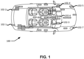
- FIG. 1 illustrates a vehicle 100 with a plurality of wireless transmitters 102, according to an embodiment.
- a vehicle 100 can have numerous sensors distributed throughout the vehicle 100. These sensors can include but are not limited to collision impact sensors to deploy the vehicle's airbags, moisture sensors to activate the windshield wipers, light sensors to automatically activate the vehicle lights, and tire pressure-monitoring sensors.
- sensors can include but are not limited to collision impact sensors to deploy the vehicle's airbags, moisture sensors to activate the windshield wipers, light sensors to automatically activate the vehicle lights, and tire pressure-monitoring sensors.
- Currently many of sensors have wired connections to send messages to the vehicle's dashboard or computer system.
- wireless transmitters 102-1 through 102-7 are distributed throughout the vehicle 100.
- wireless transmitters can be susceptible to radio frequency (RF) interference from other RF transmissions that can originate from other vehicles.
- RF radio frequency
- the wireless transmitters can be affected by external sensors.
- sensors in the rear of the vehicle e.g., sensors 102-1 and 102-2
- external sources e.g., other vehicles
- the distribution of wireless transmitters (102-1 to 102-7) shown in FIG. 1 is provided as an example. Sensor locations may vary depending on vehicle type, employed technologies, and/or other factors.
- FIG. 2 illustrates exemplary encounters 200, 210 for possible interference for wireless sensors between vehicles.
- FIG. 2 illustrates two vehicles 202 in close vicinity on a divided roadway.
- a first vehicle 202-1 can include a plurality of wireless transmitters, and a second vehicle 202-2 can also include wireless transmitters that can operate in the same RF band as the wireless transmitters in the first vehicle 202-1.
- the two vehicles are traveling in opposite directions and the wireless sensors on the first vehicle 202-1 may be initially subject to interference on the front-driver side from transmissions from the second vehicle 202-2.
- the interference may travel from the front diver-side of the second vehicle 202-2 to the rear driver-side.
- the intensity of the interference can be affected by the distance between the first vehicle 202-1 and the second vehicle 202-2.
- the first vehicle 202-1 and the second vehicle 202-2 are travelling in the same direction.
- the wireless sensors on the first vehicle 202-1 may be subject to interference on the passenger side rear from transmissions from the second vehicle 202-2.
- the interference may travel from the passenger side rear of the first vehicle 202-1 to the front passenger side, if the second vehicle 202-2 passes the first vehicle 202-1.
- the intensity of the interference can be affected by the distance between the first vehicle 202-1 and the second vehicle 202-2.
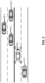
- FIG. 3 illustrates an exemplary technique of using existing on-board sensors to determine a location and motion state of other vehicles.
- Modern vehicles can include a plurality of on-board sensors (e.g., camera, LIDAR, radar, ultra-sound).
- a front camera can be installed on the top center of the windshield.
- radar sensors can be located in the front and rear corners of the vehicle.
- side mounted cameras can be installed on the side-doors of vehicles.
- these on-board sensors can be used for various automated driving features (e.g., emergency braking features, adaptive cruise control, lane centering).
- These on-board sensors in a first vehicle 302-1 can be used to detect a distance and an aspect of one or more vehicles in a vicinity of the first vehicle 302-1.
- the first vehicle 302-1 can use these on-board sensors to determine a location and/or motion state of a second vehicle 302-2 a third vehicle 302-3.
- the on-board sensors can determine a location and/or motion state of vehicles farther away, such a fourth vehicle 302-4 and a fifth vehicle 302-5.
- the location of vehicles 302-2, 302-3, 302-4, and/or 302-5 can be determined by the first vehicle 302-1, for example, by obtaining a distance and an angular measurement returned signals from transmitted signals from that reflect off of vehicles.
- Active sensors that transmit signals and can obtain distance and/or angular measurements from such returned signals include, for example, LIDAR, radar, and ultra-sound sensors.
- Distance can be determined, for example, by measuring the time difference between transmitting a signal (e.g., light, electromagnetic, and sound) and receiving the return signal.
- the propagation speed of the transmitted signal is a known quantity. Therefore, the distance can be calculated by multiplying the propagation speed of the signal by the travel time.
- an angular measurement of vehicles 302-2, 302-3, 302-4, and/or 302-5 can be determined, for example, by the location of a sensor on the first vehicle 302-1 that receives the return signals (e.g., light, electromagnetic, radar, and sound, which also may be used for distance determination as previously described). For instance, an angle or direction of the third vehicle 302-3 relative to the first vehicle 302-1 can be determined if the signal is received by a sensor on the driver's side of the first vehicle 302-1.
- the return signals e.g., light, electromagnetic, radar, and sound, which also may be used for distance determination as previously described.
- an angle or direction of the third vehicle 302-3 relative to the first vehicle 302-1 can be determined if the signal is received by a sensor on the driver's side of the first vehicle 302-1.
- the first vehicle 302-1 can determine a location of the third vehicle 302-3.
- the determined location of the third vehicle 302-3 may be relative to the first vehicle 302-1. Additionally or alternatively, the determined location may be absolute and/or relative to another object, area, or region (which may be determined based on a known absolute/relative location of the first vehicle 302-1).
- a return signal received by the first vehicle 302-1 from a reflection of a transmitted signal off of the third vehicle 302-3 may be Doppler shifted due to the motion of the third vehicle 302-3 relative to the first vehicle 302-1. That is, the returned signal may have a higher or lower frequency than the corresponding transmitted signal.
- a sensor that receives a returned signal that experiences a Doppler shift to a higher frequency indicates the object (off of which the signal reflected) is moving toward the sensor, whereas a Doppler shift to a lower frequency) indicates the object is moving away from the sensor.
- the amount of shift can indicate the relative speed of the movement.
- the Doppler shift and a known heading information for the first vehicle 302-1 can be used to determine the heading of the one or more other vehicles.
- the first vehicle 302-1 may determine a motion state (e.g., velocity and/or heading) of one or more nearby vehicles 302-2, 302-3, 302-4, and/or 302-5.
- the first vehicle 302-1 may use one or more passive sensors (which do not transmit signals) to determine location and/or speed of other vehicles. For example, using image processing to implement object detection, a camera at a fixed location on the first vehicle 302-1 may identify an object within the camera's field of view and determine the object's location based on the area within the camera's field of view (e.g., pixels of the camera's sensor) in which the object is detected. Moreover, according to some embodiments, tracking techniques may be used to track the object from one camera image to another (e.g., between frames of video), to determine the object's speed and/or heading.
- passive sensors which do not transmit signals
- FIG. 4 is an illustration of an embodiment of a V2X vehicle 402.
- a V2X vehicle 402 can broadcast one or more messages using RF signals 404.
- the messages which can include static and dynamic information of the V2X vehicle (along with other information), may be broadcast at regular intervals.
- the V2X vehicle 402 can broadcast using application-layer messages defined by SAE, ETS-ITS, C-SAE/C-ITS.
- the broadcast information messages can include V2X vehicle 402 location, vehicle heading, and vehicle speed.
- messages sent by the V2X vehicle 402 may include a BSM.
- a BSM can include a packet of data that contains information about vehicle position, heading, speed, and other information relating to a vehicle's state and predicted path.
- the BSM may contain no personally identifying information (PII) but may identify the type and model of the vehicles. In this way, a receiving V2X vehicle 402 can determine the wireless network configuration on the vehicle.
- PII personally identifying information
- a V2X device and be an electronic device (e.g., a smartphone) deployed with a V2X chipset to provide motion information and driving intention to assist strategy settings of the edge network devices.
- a V2X vehicle 402 may comprise a vehicle with such a V2X device located therein or thereon.
- Smartphones with V2X chipsets can access motion and sensor data of an associated vehicle through wired or wireless connection. If there is no direct connection to the vehicle, smartphones with sensors and GPS can provide information such as location, speed, acceleration for calculations of recommended route, recommended speed, and recommended lane.
- the V2X vehicle 402 can periodically broadcast its motion state directly to all V2X devices (including edge network devices and other vehicles within message coverage areas) in real time or near real time. Additionally or alternatively, network-based connections (e.g., Uu connections) can enable the V2X vehicle 402 to transmit vehicle information to associated edge network devices. In addition to motion state and/or vehicle information (e.g., in a BSM or CAM), the V2X vehicle 402 may send intention information, such as driving destination, desired directions, or lane change intentions.
- intention information such as driving destination, desired directions, or lane change intentions.
- FIG. 5 illustrates a roadway segment 500 with a plurality of vehicles 502-1 through 502-5 (collectively and generically referred to herein as vehicles 502), according to an example.
- each vehicle 502 comprises a V2X vehicle that can transmit and receive V2X messages in the manner previously described.
- Each V2X message can include the location and motion state of adjacent vehicles.
- a first vehicle 502-1 can receive V2X messages sent from a second vehicle 502-2, a third vehicle 502-3, a fourth vehicle 502-4, and a fifth vehicle 502-5, where each message includes a location and motion state of the vehicle 502 sending the message.
- five vehicles are depicted in the example of FIG. 5 , different situations may include any number of vehicles.
- A-priori knowledge of a potential interferer such as detection of an oncoming vehicle, enables pro-active mitigation steps.
- the system can also note and adjust a recorded reliability of particular sensors based on the wireless network interference. In this way the reliability can be used for subsequent vehicle designs, sensor selection, or mitigation strategies armed with the knowledge of potential sources of interference.
- the method 600 can include using the V2X broadcast messages to determine a location and motion state of the transmitting V2X entities.
- the V2X broadcast messages can information that can include one or more of a location of the one or more vehicles, a speed of the one or more vehicles, a heading of the one or more vehicles, an identification of the one or more vehicles, a type and model of the one or more vehicles, and a wireless network configuration of the one or more vehicles.
- the location of the one or more vehicles can be provided by a vehicle's navigation sensors (e.g., GNSS sensors).
- the location of the one more vehicles can be determined by User Equipment (UE) assisted/UE based and/or network based procedures/methods, such as Assisted GNSS (A-GNSS), Observed Time Difference Of Arrival (OTDOA), Real Time Kinematics (RTK), Precise Point Positioning (PPP), Differential GNSS (DGNSS), Enhanced Cell Identity (ECID), angle of arrival (AOA), angle of departure (AOD), Wireless Local Area Network (WLAN) positioning, and/or other positioning procedures and methods.
- Network based positioning procedures and methods may include the use of a wireless network comprising a mobile communication network (e.g. LTE or NR), WLAN, Bluetooth network, and/or other wireless networks.
- the method 600 can include detecting adjacent vehicles (approaching receding, alongside) via on-board sensors (e.g., camera, LIDAR, radar, ultrasound).
- the on-board sensors can include active sensors (e.g., LIDAR, radar, and ultrasound) that transmit a signal from the non-V2X vehicle that reflects off the one or more adjacent vehicles and is received by the receiver of the non-V2X vehicle.
- the round-trip time of the active signal can be used to calculate a distance to the one or more adjacent vehicles.
- the frequency shift of the active signal can be used to calculate a relative velocity of the one or more adjacent vehicles.
- Non-active sensors, such as cameras may be used to measure speed, heading, and/or location in the manner previously described.
- the method 600 can include invoking one or more appropriate interference mitigation techniques.
- interference mitigation techniques can include, for example, increasing or decreasing a power of a wireless transmitter of the wireless network, changing a frequency or a channel of a wireless transmitter of the wireless network, increasing or decreasing a gain level of a wireless receiver of the wireless network, and/or activating one or more additional wireless transmitters as relays to improve reliability of the wireless network.
- Additional or alternative interference mitigation techniques can include vehicle movement, such as changing lanes, speed, route, and/or spacing between vehicles.
- FIG. 6 provides for the detection and mitigation of wireless network signals according to various embodiments of the present disclosure.
- Other sequences of steps may also be performed according to alternative embodiments.
- alternative embodiments of the present disclosure may perform the steps outlined above in a different order and/or otherwise rearranged.
- the functions at blocks 602 and 604 may be omitted.
- the individual steps illustrated in FIG. 7 may include multiple sub-steps that may be performed in various sequences as appropriate to the individual step.
- additional steps may be added or removed depending on the particular applications.
- One of ordinary skill in the art would recognize many variations, modifications, and alternatives.
- FIG. 7 is a flow diagram of a method 700 for detecting and mitigating RF interference at a first vehicle, according to embodiment.
- Alternative embodiments may vary in function by combining, separating, or otherwise varying the functionality described in the blocks illustrated in FIG. 7 .
- Means for performing the functionality of one or more of the blocks illustrated in FIG. 7 may comprise hardware and/or software components of a vehicle computer system, such as the vehicle computer system 810 illustrated in FIG. 8 and described below.
- detecting the one or more vehicles within a threshold distance of the first vehicle may comprise receiving one or more return signals from a sensor of the first vehicle, determining a distance of the one or more vehicles based on the one or more return signals, and determining the distance is less than the threshold distance.
- the threshold distance may vary, depending on velocity (speed and direction) of the one or more vehicles. For example, a threshold distance for triggering an interference mitigation technique may be farther away if a detected is rapidly approaching the first vehicle than if a detected vehicle is slowly approaching the first vehicle. For detected vehicles moving away from the first vehicle, the threshold distance for triggering an interference mitigation technique may be far smaller (e.g., only triggering if the vehicle is within a short range from the first vehicle). Thus, in some embodiments of the method 700, detecting the one or more vehicles within the threshold distance may comprise determining a velocity and direction of the one or more vehicles.
- the threshold distance may be based on additional or alternative factors.
- the first vehicle may be more vulnerable to interference in some proximate locations than others (e.g., more vulnerable on the driver side than the passenger side).
- one factor that may influence the threshold distance may comprise an angle at which the first vehicle detects the one or more vehicles. Different vehicle types and models may cause different levels of interference.
- a factor that may influence the threshold distance may comprise a type and model of the one or more vehicles.
- Another factor may comprise the type of wireless network of the first vehicle, which may determine how vulnerable the wireless network is to interference.
- embodiments may employ V2X functionality to determine whether one or more vehicles are within a threshold distance, and/or obtain additional information regarding the one or more vehicles.
- the detecting the one or more vehicles proximate to the first vehicle comprises receiving one or more V2X broadcast messages from the one or more vehicles.
- Means for performing the functionality of block 702 can include, for example, wireless communication interface 830, processing unit(s) 825, DSP 820, sensor(s) 840, and/or other components of a vehicle computer system 810 as illustrated in FIG. 8 and described below.
- the method 700 includes determining a location and a motion state of the one or more vehicles. In some embodiments, this may comprise determining a relative angle of the one or more vehicles from the first vehicle and/or relative velocity between the one or more vehicles and the first vehicle. In embodiments in which V2X messages are used, determining the location and the motion state of the one or more vehicles may comprise receiving one or more V2X messages from the one or more vehicles, and determining, from the one or more V2X messages, a location, a heading, and a speed of the one or more vehicles.
- Means for performing the functionality of block 704 can include, for example, wireless communication interface 830, processing unit(s) 825, DSP 820, and/or other components of a vehicle computer system 810 as illustrated in FIG. 8 and described below.
- the method 700 includes determining potential RF interference of at least a portion of a wireless network of the first vehicle by the one or more vehicles based at least in part on the determined location and the determined motion state of the one or more vehicles. In some embodiments, this may include determining a time of potential interference based at least in part on the location, the heading, and the speed of the one or more vehicles. Additionally or alternatively, determining the potential RF interference of the at least a portion of the wireless network of the first vehicle may comprise determining a portion of the wireless network vulnerable to the potential RF interference based at least in part on the location, heading, and the speed of the one or more vehicles. This determination may comprise identifying regions and/or components on the first vehicle exposed to interference by RF signals from the one or more vehicles. Means for performing the functionality of block 706 can include, for example, processing unit(s) 825, DSP 820, and/or other components of a vehicle computer system 810 as illustrated in FIG. 8 and described below.
- the method 700 includes, implementing an interference mitigation technique based at least in part on the determined location and the determined motion state of the one or more vehicles.
- Means for performing the functionality of block 706 can include, for example, processing unit(s) 825, DSP 820, and/or other components of a vehicle computer system 810 as illustrated in FIG. 8 and described below.
- interference mitigation techniques may vary, depending on desired functionality. Such techniques can include, for example, increasing or decreasing a power of a wireless transmitter of the wireless network, changing a frequency or a channel of a wireless transmitter of the wireless network, increasing or decreasing a gain level of a wireless receiver of the wireless network, activating one or more additional wireless transmitters of the wireless network, and/or any combination thereof.
- Increasing or decreasing a power of a wireless transmitter can, for example, adjust Signal-To-Noise Ratio (SNR) levels within the wireless network to suitable ranges to help ensure reliable wireless communication despite the potential interference.
- SNR Signal-To-Noise Ratio
- Increasing or decreasing a gain level may have a similar effect, but at the receiver side of a wireless link.
- Changing a frequency or channel of a wireless transmitter can help reduce interference where a frequency or channel of the potential RF interference is known or can be predicted (e.g., is detected by one or more components of the first vehicle and/or determined based on vehicle type, model, and/or other factors).
- Activating one or more additional wireless transmitters of the wireless network may help boost signal strength within the wireless network, which again can help ensure the reliability of communications within the wireless network.
- FIG. 7 provides particular techniques for detecting and mitigation wireless network signals according to various embodiments of the present disclosure. Other sequences of steps may also be performed according to alternative embodiments. For example, alternative embodiments of the present disclosure may perform the steps outlined above in a different order. Moreover, the individual steps illustrated in FIG. 7 may include multiple sub-steps that may be performed in various sequences as appropriate to the individual step. Furthermore, additional steps may be added or removed depending on the particular applications. One of ordinary skill in the art would recognize many variations, modifications, and alternatives.
- FIG. 8 is a block diagram of an embodiment of a vehicle computer system 810, which may be utilized as described herein above.
- the vehicle computer system 810 may comprise or be integrated into one or more additional vehicular systems, such as those related to the vehicle's navigation and/or automated driving. As such, components shown may be capable of communicating with other onboard systems and/or other traffic entities (not shown).
- the vehicle computer system 810 may comprise a stand-alone device or component on a vehicle, which may be communicatively coupled with other components/devices of the vehicle (or entity).
- the vehicle computer system 810 may comprise a V2X device and/or may be otherwise capable of allowing a vehicle to engage in V2X communications and functionality.
- the vehicle computer system 810 may implement an application layer and radio layer and may perform one or more of the functions of method 700 of FIG. 7 .
- the application layer may be executed by the processing unit(s) 825, and the radio layer may be executed by the wireless communication interface 830.
- the application layer and/or radio layer may be implemented by additional or alternative components.
- FIG. 8 is meant only to provide a generalized illustration of various components, any or all of which may be utilized as appropriate. It can be noted that, in some instances, components illustrated by FIG. 8 can be localized to a single physical device and/or distributed among various networked devices, which may be located, for example, at different physical locations on a vehicle.
- a wireless network of a vehicle may comprise sensors and/or other wireless components located on the vehicle.
- the vehicle computer system 810 may communicate with the wireless network via the wireless communication interface 830.
- the vehicle computer system 810 is shown comprising hardware elements that can be electrically coupled via a bus 805 or may otherwise be in communication, as appropriate.
- one or more of the components illustrated in the vehicle computer system 810 may be wirelessly connected (and therefore may be part of a wireless network of a vehicle, as described in embodiments herein).
- the hardware elements may include a processing unit(s) 825 which can include without limitation one or more general-purpose processors, one or more special-purpose processors (such as digital signal processing (DSP) chips, graphics acceleration processors, application-specific integrated circuits (ASICs), and/or the like), and/or other processing structure or means. As shown in FIG.
- DSP digital signal processing
- ASICs application-specific integrated circuits
- DSP Digital Signal Processor
- the vehicle computer system 810 also can include one or more input devices 870, which can include devices related to user interface (e.g., a touch screen, touchpad, microphone, button(s), dial(s), switch(es), and/or the like) and/or devices related to navigation, automated driving, and the like.
- the one or more output devices 815 may be related to interacting with a user (e.g., via a display, light emitting diode(s) (LED(s)), speaker(s), etc.), and/or devices related to navigation, automated driving, and the like.
- the vehicle computer system 810 may also include a wireless communication interface 830, which may comprise without limitation a modem, a network card, an infrared communication device, a wireless communication device, and/or a chipset (such as a Bluetooth ® device, an IEEE 802.11 device, an IEEE 802.15.4 device, a Wi-Fi device, a WiMAX device, a WAN device and/or various cellular devices, etc.), and/or the like.
- the wireless communication interface 830 can enable the vehicle computer system 810 to communicate to other devices, including V2X devices (in some embodiments), remote from the vehicle. As previously noted, additionally or alternatively may be used to communicate with a wireless network of the vehicle.
- Communication using the wireless communication interface 830 can be carried out via one or more wireless communication antenna(s) 832 that send and/or receive wireless signals 834.
- the wireless communication antenna(s) 832 may comprise a plurality of discrete antennas, antenna arrays, or any combination thereof.
- the wireless communication interface 830 may comprise a separate receiver and transmitter, or any combination of transceivers, transmitters, and/or receivers to communicate with base stations of a mobile carrier network and/or other terrestrial transceivers, such as wireless devices and access points.
- the wireless communication interface 830 may allow the vehicle to communicate with different data networks that may comprise various network types.
- a Wireless Wide Area Network may be a Code Division Multiple Access (CDMA) network, a Time Division Multiple Access (TDMA) network, a Frequency Division Multiple Access (FDMA) network, an Orthogonal Frequency Division Multiple Access (OFDMA) network, a Single-Carrier Frequency Division Multiple Access (SC-FDMA) network, a WiMAX (IEEE 802.16) network, and so on.
- CDMA network may implement one or more radio access technologies such as CDMA2000, Wideband Code Division Multiple Access (WCDMA), and so on.
- CDMA2000 includes IS-95, IS-2000 and/or IS-856 standards.
- a TDMA network may implement Global System for Mobile Communications (GSM), Digital Advanced Mobile Phone System (D-AMPS), or some other RAT.
- GSM Global System for Mobile Communications
- D-AMPS Digital Advanced Mobile Phone System
- An OFDMA network may employ LTE, LTE Advanced, 5G NR, and so on.
- 5G NR, LTE, LTE Advanced, GSM, and WCDMA are described in documents from 3GPP.
- Cdma2000 is described in documents from a consortium named "3rd Generation Partnership Project X3" (3GPP2).
- 3GPP and 3GPP2 documents are publicly available.
- a wireless local area network (WLAN) may also be an IEEE 802.11x network
- a wireless personal area network (WPAN) may be a Bluetooth network, an IEEE 802.15x, or some other type of network.
- the vehicle computer system 810 can further include sensor(s) 840.
- Sensors 840 may comprise, without limitation, one or more accelerometers, gyroscopes, cameras, magnetometers, altimeters, microphones, proximity sensors, light sensors, barometers, radar, lidar, ultrasonic sensors, and the like. As previously noted, sensor(s) 840 may be used to determine certain real-time characteristics of the vehicle, such as location, velocity, acceleration, and the like. Additionally or alternatively sensor(s) 840 may be used to determine characteristics of nearby vehicles and other objects as described herein.
- Embodiments of the vehicle computer system 810 may also include a GNSS receiver 880 capable of receiving signals 884 from one or more GNSS satellites using an antenna 882 (which could be the same as antenna 832). Positioning based on GNSS signal measurement can be utilized to determine a current location of the vehicle and further may be used as a basis to determine the location of nearby detected objects, including other vehicles.
- the GNSS receiver 880 can extract a position of the vehicle computer system 810, using conventional techniques, from GNSS satellites of a GNSS system, such as Global Positioning System (GPS) and/or similar satellite systems.
- GPS Global Positioning System
- the vehicle computer system 810 may further comprise and/or be in communication with a memory 860.
- the memory 860 can include, without limitation, local and/or network accessible storage, a disk drive, a drive array, an optical storage device, a solid-state storage device, such as a random access memory (RAM), and/or a read-only memory (ROM), which can be programmable, flash-updateable, and/or the like.
- RAM random access memory
- ROM read-only memory
- Such storage devices may be configured to implement any appropriate data stores, including without limitation, various file systems, database structures, and/or the like.
- the memory 860 of the vehicle computer system 810 also can comprise software elements (not shown in FIG. 8 ), including an operating system, device drivers, executable libraries, and/or other code, such as one or more application programs, which may comprise computer programs provided by various embodiments, and/or may be designed to implement methods and/or configure systems as described herein.
- Software applications stored in memory 860 and executed by processing unit(s) 825 may be used to implement the application layer.
- one or more procedures described with respect to the method(s) discussed herein may be implemented as code and/or instructions in memory 860 that are executable by the vehicle computer system 810 (and/or processing unit(s) 825 or DSP 820 within vehicle computer system 810), including the functions illustrated in the method 600 of FIG. 6 .
- code and/or instructions can be used to configure and/or adapt a general-purpose computer (or other device) to perform one or more operations in accordance with the described methods.
- components that can include memory can include non-transitory machine-readable media.
- machine-readable medium and “computer-readable medium” as used herein refer to any storage medium that participates in providing data that causes a machine to operate in a specific fashion.
- various machine-readable media might be involved in providing instructions/code to processing units 825 and/or other device(s) for execution. Additionally or alternatively, the machine-readable media might be used to store and/or carry such instructions/code.
- a computer-readable medium is a physical and/or tangible storage medium. Such a medium may take many forms, including but not limited to, non-volatile media, volatile media, and transmission media.
- Computer-readable media include, for example, magnetic and/or optical media, any other physical medium with patterns of holes, RAM, a programmable ROM (PROM), erasable programmable ROM (EPROM), a FLASH-EPROM, any other memory chip or cartridge, a carrier wave as described hereinafter, or any other medium from which a computer can read instructions and/or code.
- PROM programmable ROM
- EPROM erasable programmable ROM
- FLASH-EPROM any other memory chip or cartridge
- carrier wave as described hereinafter
- a special purpose computer or a similar special purpose electronic computing device is capable of manipulating or transforming signals, typically represented as physical electronic, electrical, or magnetic quantities within memories, registers, or other information storage devices, transmission devices, or display devices of the special-purpose computer or similar special-purpose electronic computing device.
- the term "at least one of” if used to associate a list, such as A, B, or C, can be interpreted to mean any combination of A, B, and/or C, such as A, AB, AA, AAB, AABBCCC, etc.
Landscapes
- Engineering & Computer Science (AREA)
- Computer Networks & Wireless Communication (AREA)
- Signal Processing (AREA)
- Quality & Reliability (AREA)
- Physics & Mathematics (AREA)
- Electromagnetism (AREA)
- Automation & Control Theory (AREA)
- Transportation (AREA)
- Mechanical Engineering (AREA)
- Traffic Control Systems (AREA)
- Mobile Radio Communication Systems (AREA)
Applications Claiming Priority (3)
| Application Number | Priority Date | Filing Date | Title |
|---|---|---|---|
| US202062962463P | 2020-01-17 | 2020-01-17 | |
| US16/997,810 US11910283B2 (en) | 2020-01-17 | 2020-08-19 | Wireless in-vehicle networking enhanced interference detection via external sensors |
| PCT/US2020/063136 WO2021145969A1 (en) | 2020-01-17 | 2020-12-03 | Wireless in-vehicle networking enhanced interference detection via external sensors |
Publications (2)
| Publication Number | Publication Date |
|---|---|
| EP4091389A1 EP4091389A1 (en) | 2022-11-23 |
| EP4091389B1 true EP4091389B1 (en) | 2025-03-12 |
Family
ID=76857413
Family Applications (1)
| Application Number | Title | Priority Date | Filing Date |
|---|---|---|---|
| EP20828228.5A Active EP4091389B1 (en) | 2020-01-17 | 2020-12-03 | Wireless in-vehicle networking enhanced interference detection via external sensors |
Country Status (9)
| Country | Link |
|---|---|
| US (1) | US11910283B2 (cg-RX-API-DMAC7.html) |
| EP (1) | EP4091389B1 (cg-RX-API-DMAC7.html) |
| JP (1) | JP7587585B2 (cg-RX-API-DMAC7.html) |
| KR (1) | KR20220128997A (cg-RX-API-DMAC7.html) |
| CN (1) | CN114946253B (cg-RX-API-DMAC7.html) |
| BR (1) | BR112022013680A2 (cg-RX-API-DMAC7.html) |
| PH (1) | PH12022551473A1 (cg-RX-API-DMAC7.html) |
| TW (1) | TW202137790A (cg-RX-API-DMAC7.html) |
| WO (1) | WO2021145969A1 (cg-RX-API-DMAC7.html) |
Families Citing this family (7)
| Publication number | Priority date | Publication date | Assignee | Title |
|---|---|---|---|---|
| EP3866497B1 (en) * | 2020-02-11 | 2025-12-17 | Volkswagen Ag | Vehicle, network entity, apparatuses, methods, and computer programs for communicating messages with other vehicles and for adapting a physical layer configuration |
| US11563503B2 (en) * | 2020-09-15 | 2023-01-24 | Ford Global Technologies, Llc | Vehicle Wi-Fi access point detection and mitigation |
| CN112285717B (zh) * | 2020-10-29 | 2024-08-06 | 腾讯科技(深圳)有限公司 | 控制车载雷达信号的方法以及电子设备 |
| KR20220093883A (ko) * | 2020-12-28 | 2022-07-05 | 현대자동차주식회사 | 차량 및 그 제어 방법 |
| US20220376921A1 (en) * | 2021-05-21 | 2022-11-24 | At&T Mobility Ii Llc | Blockchain authenticator for dynamic spectrum sharing and blockchain cybersecurity services |
| US12426089B2 (en) * | 2021-09-22 | 2025-09-23 | Apple Inc. | Selective cellular interference mitigation for GNSS |
| US20250141637A1 (en) * | 2023-10-25 | 2025-05-01 | GM Global Technology Operations LLC | System and method for cross technology radio frequency interference mitigation |
Family Cites Families (12)
| Publication number | Priority date | Publication date | Assignee | Title |
|---|---|---|---|---|
| CN102100117B (zh) * | 2008-06-06 | 2014-08-13 | 三菱电机株式会社 | 车载无线通信系统 |
| US8250695B2 (en) * | 2009-10-05 | 2012-08-28 | Applied Materials, Inc. | Roller assembly for a brush cleaning device in a cleaning module |
| JP6064430B2 (ja) * | 2012-08-15 | 2017-01-25 | 沖電気工業株式会社 | 無線装置 |
| CN105992256B (zh) | 2015-03-03 | 2019-08-27 | 华为技术有限公司 | 轨道交通中的无线局域网的信道管理方法,设备和系统 |
| US9661598B2 (en) | 2015-09-30 | 2017-05-23 | Mitsubishi Electric Research Laboratories, Inc. | System and method for reducing interference between multiple terminals |
| EP3349372B1 (en) * | 2017-01-11 | 2019-12-04 | Volkswagen Aktiengesellschaft | Method for adjusting the interference level for a wireless communication from a first mobile station to a second mobile station and adapted mobile station for the use in the method and adapted vehicle |
| JP6685963B2 (ja) | 2017-03-27 | 2020-04-22 | 京セラ株式会社 | 電子機器、電子機器の制御方法および制御プログラム |
| WO2018182706A1 (en) | 2017-03-31 | 2018-10-04 | Intel Corporation | Dynamic beam steering for vehicle communications |
| KR102281655B1 (ko) * | 2017-06-30 | 2021-07-29 | 현대자동차주식회사 | 차량용 무선 통신 관리 시스템 및 그 제어방법 |
| EP3775972A1 (en) | 2018-03-26 | 2021-02-17 | Qualcomm Incorporated | Using a side-communication channel for exchanging radar information to improve multi-radar coexistence |
| US10491312B1 (en) * | 2018-09-05 | 2019-11-26 | Toyota Jidosha Kabushiki Kaisha | Simultaneous reception of vehicle-to-everything (V2X) messages over multiple channels in multi-channel V2X networks |
| JP2020065139A (ja) | 2018-10-16 | 2020-04-23 | シャープ株式会社 | 端末装置、通信システム、通信方法及びプログラム |
-
2020
- 2020-08-19 US US16/997,810 patent/US11910283B2/en active Active
- 2020-12-03 JP JP2022543021A patent/JP7587585B2/ja active Active
- 2020-12-03 CN CN202080092627.8A patent/CN114946253B/zh active Active
- 2020-12-03 WO PCT/US2020/063136 patent/WO2021145969A1/en not_active Ceased
- 2020-12-03 KR KR1020227023863A patent/KR20220128997A/ko active Pending
- 2020-12-03 EP EP20828228.5A patent/EP4091389B1/en active Active
- 2020-12-03 BR BR112022013680A patent/BR112022013680A2/pt unknown
- 2020-12-04 TW TW109142921A patent/TW202137790A/zh unknown
- 2020-12-30 PH PH1/2022/551473A patent/PH12022551473A1/en unknown
Also Published As
| Publication number | Publication date |
|---|---|
| TW202137790A (zh) | 2021-10-01 |
| PH12022551473A1 (en) | 2023-11-29 |
| JP7587585B2 (ja) | 2024-11-20 |
| KR20220128997A (ko) | 2022-09-22 |
| CN114946253B (zh) | 2025-02-28 |
| US20210227365A1 (en) | 2021-07-22 |
| BR112022013680A2 (pt) | 2022-09-13 |
| JP2023511544A (ja) | 2023-03-20 |
| CN114946253A (zh) | 2022-08-26 |
| US11910283B2 (en) | 2024-02-20 |
| EP4091389A1 (en) | 2022-11-23 |
| WO2021145969A1 (en) | 2021-07-22 |
Similar Documents
| Publication | Publication Date | Title |
|---|---|---|
| EP4091389B1 (en) | Wireless in-vehicle networking enhanced interference detection via external sensors | |
| CN114731494B (zh) | 具有传感器辅助的v2x通信 | |
| US11194057B2 (en) | ASIL-classification by cooperative positioning | |
| TWI904178B (zh) | 用於在v2x環境中管理資料分發的技術 | |
| US10531254B2 (en) | Millimeter wave vehicle-to-vehicle communication system for data sharing | |
| US12017659B2 (en) | Vehicle-originated wireless safety alert | |
| US20230131851A1 (en) | Priority indication in maneuver coordination message | |
| US11412363B2 (en) | Context-adaptive RSSI-based misbehavior detection | |
| US11638237B2 (en) | Geometry-based listen-before-talk (LBT) sensing for traffic-related physical ranging signals | |
| CN112970051A (zh) | 信息处理装置以及驾驶支援装置 | |
| US20210385619A1 (en) | Position estimation of a pedestrian user equipment | |
| US20240160219A1 (en) | Automated platooning system and method thereof | |
| EP4071498A1 (en) | Methods for radar interference mitigation with broadcasting center | |
| US20220159429A1 (en) | Adaptive rssi adjustment | |
| KR20230107037A (ko) | 차량의 전방충돌 방지장치 및 그의 제어 방법 |
Legal Events
| Date | Code | Title | Description |
|---|---|---|---|
| STAA | Information on the status of an ep patent application or granted ep patent |
Free format text: STATUS: UNKNOWN |
|
| STAA | Information on the status of an ep patent application or granted ep patent |
Free format text: STATUS: THE INTERNATIONAL PUBLICATION HAS BEEN MADE |
|
| PUAI | Public reference made under article 153(3) epc to a published international application that has entered the european phase |
Free format text: ORIGINAL CODE: 0009012 |
|
| STAA | Information on the status of an ep patent application or granted ep patent |
Free format text: STATUS: REQUEST FOR EXAMINATION WAS MADE |
|
| 17P | Request for examination filed |
Effective date: 20220701 |
|
| AK | Designated contracting states |
Kind code of ref document: A1 Designated state(s): AL AT BE BG CH CY CZ DE DK EE ES FI FR GB GR HR HU IE IS IT LI LT LU LV MC MK MT NL NO PL PT RO RS SE SI SK SM TR |
|
| DAV | Request for validation of the european patent (deleted) | ||
| DAX | Request for extension of the european patent (deleted) | ||
| REG | Reference to a national code |
Ref country code: DE Free format text: PREVIOUS MAIN CLASS: H04W0072080000 Ipc: H04B0017270000 Ref country code: DE Ref legal event code: R079 Ref document number: 602020047681 Country of ref document: DE Free format text: PREVIOUS MAIN CLASS: H04W0072080000 Ipc: H04B0017270000 |
|
| GRAP | Despatch of communication of intention to grant a patent |
Free format text: ORIGINAL CODE: EPIDOSNIGR1 |
|
| STAA | Information on the status of an ep patent application or granted ep patent |
Free format text: STATUS: GRANT OF PATENT IS INTENDED |
|
| RIC1 | Information provided on ipc code assigned before grant |
Ipc: H04W 72/0453 20230101ALN20241016BHEP Ipc: H04W 4/48 20180101ALN20241016BHEP Ipc: H04W 72/02 20090101ALN20241016BHEP Ipc: H04W 64/00 20090101ALN20241016BHEP Ipc: H04W 84/00 20090101ALN20241016BHEP Ipc: H04W 72/541 20230101ALI20241016BHEP Ipc: H04B 17/345 20150101ALI20241016BHEP Ipc: H04B 17/27 20150101AFI20241016BHEP |
|
| INTG | Intention to grant announced |
Effective date: 20241024 |
|
| GRAS | Grant fee paid |
Free format text: ORIGINAL CODE: EPIDOSNIGR3 |
|
| GRAA | (expected) grant |
Free format text: ORIGINAL CODE: 0009210 |
|
| STAA | Information on the status of an ep patent application or granted ep patent |
Free format text: STATUS: THE PATENT HAS BEEN GRANTED |
|
| AK | Designated contracting states |
Kind code of ref document: B1 Designated state(s): AL AT BE BG CH CY CZ DE DK EE ES FI FR GB GR HR HU IE IS IT LI LT LU LV MC MK MT NL NO PL PT RO RS SE SI SK SM TR |
|
| REG | Reference to a national code |
Ref country code: GB Ref legal event code: FG4D |
|
| REG | Reference to a national code |
Ref country code: CH Ref legal event code: EP |
|
| REG | Reference to a national code |
Ref country code: DE Ref legal event code: R096 Ref document number: 602020047681 Country of ref document: DE |
|
| REG | Reference to a national code |
Ref country code: IE Ref legal event code: FG4D |
|
| PG25 | Lapsed in a contracting state [announced via postgrant information from national office to epo] |
Ref country code: RS Free format text: LAPSE BECAUSE OF FAILURE TO SUBMIT A TRANSLATION OF THE DESCRIPTION OR TO PAY THE FEE WITHIN THE PRESCRIBED TIME-LIMIT Effective date: 20250612 |
|
| PG25 | Lapsed in a contracting state [announced via postgrant information from national office to epo] |
Ref country code: FI Free format text: LAPSE BECAUSE OF FAILURE TO SUBMIT A TRANSLATION OF THE DESCRIPTION OR TO PAY THE FEE WITHIN THE PRESCRIBED TIME-LIMIT Effective date: 20250312 |
|
| PG25 | Lapsed in a contracting state [announced via postgrant information from national office to epo] |
Ref country code: ES Free format text: LAPSE BECAUSE OF FAILURE TO SUBMIT A TRANSLATION OF THE DESCRIPTION OR TO PAY THE FEE WITHIN THE PRESCRIBED TIME-LIMIT Effective date: 20250312 |
|
| REG | Reference to a national code |
Ref country code: LT Ref legal event code: MG9D |
|
| PG25 | Lapsed in a contracting state [announced via postgrant information from national office to epo] |
Ref country code: NO Free format text: LAPSE BECAUSE OF FAILURE TO SUBMIT A TRANSLATION OF THE DESCRIPTION OR TO PAY THE FEE WITHIN THE PRESCRIBED TIME-LIMIT Effective date: 20250612 |
|
| PG25 | Lapsed in a contracting state [announced via postgrant information from national office to epo] |
Ref country code: HR Free format text: LAPSE BECAUSE OF FAILURE TO SUBMIT A TRANSLATION OF THE DESCRIPTION OR TO PAY THE FEE WITHIN THE PRESCRIBED TIME-LIMIT Effective date: 20250312 |
|
| REG | Reference to a national code |
Ref country code: NL Ref legal event code: MP Effective date: 20250312 |
|
| PG25 | Lapsed in a contracting state [announced via postgrant information from national office to epo] |
Ref country code: LV Free format text: LAPSE BECAUSE OF FAILURE TO SUBMIT A TRANSLATION OF THE DESCRIPTION OR TO PAY THE FEE WITHIN THE PRESCRIBED TIME-LIMIT Effective date: 20250312 |
|
| PG25 | Lapsed in a contracting state [announced via postgrant information from national office to epo] |
Ref country code: GR Free format text: LAPSE BECAUSE OF FAILURE TO SUBMIT A TRANSLATION OF THE DESCRIPTION OR TO PAY THE FEE WITHIN THE PRESCRIBED TIME-LIMIT Effective date: 20250613 Ref country code: BG Free format text: LAPSE BECAUSE OF FAILURE TO SUBMIT A TRANSLATION OF THE DESCRIPTION OR TO PAY THE FEE WITHIN THE PRESCRIBED TIME-LIMIT Effective date: 20250312 |
|
| REG | Reference to a national code |
Ref country code: AT Ref legal event code: MK05 Ref document number: 1775911 Country of ref document: AT Kind code of ref document: T Effective date: 20250312 |
|
| PG25 | Lapsed in a contracting state [announced via postgrant information from national office to epo] |
Ref country code: NL Free format text: LAPSE BECAUSE OF FAILURE TO SUBMIT A TRANSLATION OF THE DESCRIPTION OR TO PAY THE FEE WITHIN THE PRESCRIBED TIME-LIMIT Effective date: 20250312 |
|
| PG25 | Lapsed in a contracting state [announced via postgrant information from national office to epo] |
Ref country code: SE Free format text: LAPSE BECAUSE OF FAILURE TO SUBMIT A TRANSLATION OF THE DESCRIPTION OR TO PAY THE FEE WITHIN THE PRESCRIBED TIME-LIMIT Effective date: 20250312 |
|
| PG25 | Lapsed in a contracting state [announced via postgrant information from national office to epo] |
Ref country code: SM Free format text: LAPSE BECAUSE OF FAILURE TO SUBMIT A TRANSLATION OF THE DESCRIPTION OR TO PAY THE FEE WITHIN THE PRESCRIBED TIME-LIMIT Effective date: 20250312 |
|
| PG25 | Lapsed in a contracting state [announced via postgrant information from national office to epo] |
Ref country code: PT Free format text: LAPSE BECAUSE OF FAILURE TO SUBMIT A TRANSLATION OF THE DESCRIPTION OR TO PAY THE FEE WITHIN THE PRESCRIBED TIME-LIMIT Effective date: 20250714 |
|
| PG25 | Lapsed in a contracting state [announced via postgrant information from national office to epo] |
Ref country code: PL Free format text: LAPSE BECAUSE OF FAILURE TO SUBMIT A TRANSLATION OF THE DESCRIPTION OR TO PAY THE FEE WITHIN THE PRESCRIBED TIME-LIMIT Effective date: 20250312 Ref country code: IT Free format text: LAPSE BECAUSE OF FAILURE TO SUBMIT A TRANSLATION OF THE DESCRIPTION OR TO PAY THE FEE WITHIN THE PRESCRIBED TIME-LIMIT Effective date: 20250312 |
|
| PG25 | Lapsed in a contracting state [announced via postgrant information from national office to epo] |
Ref country code: AT Free format text: LAPSE BECAUSE OF FAILURE TO SUBMIT A TRANSLATION OF THE DESCRIPTION OR TO PAY THE FEE WITHIN THE PRESCRIBED TIME-LIMIT Effective date: 20250312 |
|
| PG25 | Lapsed in a contracting state [announced via postgrant information from national office to epo] |
Ref country code: CZ Free format text: LAPSE BECAUSE OF FAILURE TO SUBMIT A TRANSLATION OF THE DESCRIPTION OR TO PAY THE FEE WITHIN THE PRESCRIBED TIME-LIMIT Effective date: 20250312 Ref country code: EE Free format text: LAPSE BECAUSE OF FAILURE TO SUBMIT A TRANSLATION OF THE DESCRIPTION OR TO PAY THE FEE WITHIN THE PRESCRIBED TIME-LIMIT Effective date: 20250312 |
|
| PG25 | Lapsed in a contracting state [announced via postgrant information from national office to epo] |
Ref country code: RO Free format text: LAPSE BECAUSE OF FAILURE TO SUBMIT A TRANSLATION OF THE DESCRIPTION OR TO PAY THE FEE WITHIN THE PRESCRIBED TIME-LIMIT Effective date: 20250312 |
|
| PG25 | Lapsed in a contracting state [announced via postgrant information from national office to epo] |
Ref country code: SK Free format text: LAPSE BECAUSE OF FAILURE TO SUBMIT A TRANSLATION OF THE DESCRIPTION OR TO PAY THE FEE WITHIN THE PRESCRIBED TIME-LIMIT Effective date: 20250312 |
|
| PG25 | Lapsed in a contracting state [announced via postgrant information from national office to epo] |
Ref country code: IS Free format text: LAPSE BECAUSE OF FAILURE TO SUBMIT A TRANSLATION OF THE DESCRIPTION OR TO PAY THE FEE WITHIN THE PRESCRIBED TIME-LIMIT Effective date: 20250712 |
|
| REG | Reference to a national code |
Ref country code: DE Ref legal event code: R097 Ref document number: 602020047681 Country of ref document: DE |
|
| PGFP | Annual fee paid to national office [announced via postgrant information from national office to epo] |
Ref country code: DE Payment date: 20251118 Year of fee payment: 6 |
|
| PGFP | Annual fee paid to national office [announced via postgrant information from national office to epo] |
Ref country code: GB Payment date: 20251113 Year of fee payment: 6 |
|
| PG25 | Lapsed in a contracting state [announced via postgrant information from national office to epo] |
Ref country code: DK Free format text: LAPSE BECAUSE OF FAILURE TO SUBMIT A TRANSLATION OF THE DESCRIPTION OR TO PAY THE FEE WITHIN THE PRESCRIBED TIME-LIMIT Effective date: 20250312 |
|
| PGFP | Annual fee paid to national office [announced via postgrant information from national office to epo] |
Ref country code: FR Payment date: 20251111 Year of fee payment: 6 |
|
| PLBE | No opposition filed within time limit |
Free format text: ORIGINAL CODE: 0009261 |
|
| STAA | Information on the status of an ep patent application or granted ep patent |
Free format text: STATUS: NO OPPOSITION FILED WITHIN TIME LIMIT |
|
| REG | Reference to a national code |
Ref country code: CH Ref legal event code: L10 Free format text: ST27 STATUS EVENT CODE: U-0-0-L10-L00 (AS PROVIDED BY THE NATIONAL OFFICE) Effective date: 20260121 |
|
| 26N | No opposition filed |
Effective date: 20251215 |