EP4090838B1 - Verriegelungsvorrichtung und kompakte kipphebelanordnung - Google Patents
Verriegelungsvorrichtung und kompakte kipphebelanordnung Download PDFInfo
- Publication number
- EP4090838B1 EP4090838B1 EP21701209.5A EP21701209A EP4090838B1 EP 4090838 B1 EP4090838 B1 EP 4090838B1 EP 21701209 A EP21701209 A EP 21701209A EP 4090838 B1 EP4090838 B1 EP 4090838B1
- Authority
- EP
- European Patent Office
- Prior art keywords
- latch
- bore
- latch pin
- arm
- assembly
- Prior art date
- Legal status (The legal status is an assumption and is not a legal conclusion. Google has not performed a legal analysis and makes no representation as to the accuracy of the status listed.)
- Active
Links
Images


Classifications
-
- F—MECHANICAL ENGINEERING; LIGHTING; HEATING; WEAPONS; BLASTING
- F01—MACHINES OR ENGINES IN GENERAL; ENGINE PLANTS IN GENERAL; STEAM ENGINES
- F01L—CYCLICALLY OPERATING VALVES FOR MACHINES OR ENGINES
- F01L1/00—Valve-gear or valve arrangements, e.g. lift-valve gear
- F01L1/12—Transmitting gear between valve drive and valve
- F01L1/18—Rocking arms or levers
- F01L1/181—Centre pivot rocking arms
-
- F—MECHANICAL ENGINEERING; LIGHTING; HEATING; WEAPONS; BLASTING
- F01—MACHINES OR ENGINES IN GENERAL; ENGINE PLANTS IN GENERAL; STEAM ENGINES
- F01L—CYCLICALLY OPERATING VALVES FOR MACHINES OR ENGINES
- F01L1/00—Valve-gear or valve arrangements, e.g. lift-valve gear
- F01L1/46—Component parts, details, or accessories, not provided for in preceding subgroups
-
- F—MECHANICAL ENGINEERING; LIGHTING; HEATING; WEAPONS; BLASTING
- F01—MACHINES OR ENGINES IN GENERAL; ENGINE PLANTS IN GENERAL; STEAM ENGINES
- F01L—CYCLICALLY OPERATING VALVES FOR MACHINES OR ENGINES
- F01L13/00—Modifications of valve-gear to facilitate reversing, braking, starting, changing compression ratio, or other specific operations
- F01L13/0005—Deactivating valves
-
- F—MECHANICAL ENGINEERING; LIGHTING; HEATING; WEAPONS; BLASTING
- F01—MACHINES OR ENGINES IN GENERAL; ENGINE PLANTS IN GENERAL; STEAM ENGINES
- F01L—CYCLICALLY OPERATING VALVES FOR MACHINES OR ENGINES
- F01L1/00—Valve-gear or valve arrangements, e.g. lift-valve gear
- F01L1/20—Adjusting or compensating clearance
- F01L1/22—Adjusting or compensating clearance automatically, e.g. mechanically
- F01L1/24—Adjusting or compensating clearance automatically, e.g. mechanically by fluid means, e.g. hydraulically
- F01L1/2416—Adjusting or compensating clearance automatically, e.g. mechanically by fluid means, e.g. hydraulically by means of a hydraulic adjusting device attached to an articulated rocker
-
- F—MECHANICAL ENGINEERING; LIGHTING; HEATING; WEAPONS; BLASTING
- F01—MACHINES OR ENGINES IN GENERAL; ENGINE PLANTS IN GENERAL; STEAM ENGINES
- F01L—CYCLICALLY OPERATING VALVES FOR MACHINES OR ENGINES
- F01L1/00—Valve-gear or valve arrangements, e.g. lift-valve gear
- F01L1/12—Transmitting gear between valve drive and valve
- F01L1/18—Rocking arms or levers
- F01L2001/186—Split rocking arms, e.g. rocker arms having two articulated parts and means for varying the relative position of these parts or for selectively connecting the parts to move in unison
-
- F—MECHANICAL ENGINEERING; LIGHTING; HEATING; WEAPONS; BLASTING
- F01—MACHINES OR ENGINES IN GENERAL; ENGINE PLANTS IN GENERAL; STEAM ENGINES
- F01L—CYCLICALLY OPERATING VALVES FOR MACHINES OR ENGINES
- F01L1/00—Valve-gear or valve arrangements, e.g. lift-valve gear
- F01L1/46—Component parts, details, or accessories, not provided for in preceding subgroups
- F01L2001/467—Lost motion springs
-
- F—MECHANICAL ENGINEERING; LIGHTING; HEATING; WEAPONS; BLASTING
- F01—MACHINES OR ENGINES IN GENERAL; ENGINE PLANTS IN GENERAL; STEAM ENGINES
- F01L—CYCLICALLY OPERATING VALVES FOR MACHINES OR ENGINES
- F01L13/00—Modifications of valve-gear to facilitate reversing, braking, starting, changing compression ratio, or other specific operations
- F01L13/0005—Deactivating valves
- F01L2013/001—Deactivating cylinders
-
- F—MECHANICAL ENGINEERING; LIGHTING; HEATING; WEAPONS; BLASTING
- F01—MACHINES OR ENGINES IN GENERAL; ENGINE PLANTS IN GENERAL; STEAM ENGINES
- F01L—CYCLICALLY OPERATING VALVES FOR MACHINES OR ENGINES
- F01L13/00—Modifications of valve-gear to facilitate reversing, braking, starting, changing compression ratio, or other specific operations
- F01L2013/10—Auxiliary actuators for variable valve timing
- F01L2013/105—Hydraulic motors
-
- F—MECHANICAL ENGINEERING; LIGHTING; HEATING; WEAPONS; BLASTING
- F01—MACHINES OR ENGINES IN GENERAL; ENGINE PLANTS IN GENERAL; STEAM ENGINES
- F01L—CYCLICALLY OPERATING VALVES FOR MACHINES OR ENGINES
- F01L2305/00—Valve arrangements comprising rollers
Definitions
- the present disclosure relates generally to a rocker arm assembly for use in a valve train assembly and, more particularly, to a Type III valvetrain cylinder deactivation (CDA) system for providing secondary valve lift such as engine braking.
- CDA valvetrain cylinder deactivation
- a latch assembly is also provided.
- Some internal combustion engines can utilize rocker arms to transfer rotational motion of cams to linear motion appropriate for opening and closing engine valves.
- Deactivating rocker arms incorporate mechanisms that allow for selective activation and deactivation of the rocker arm. In a deactivated state, the rocker arm may exhibit lost motion movement.
- conventional valve train carrier assemblies may typically be concerned with contact stress issues, high stiffness issues, high cycle fatigue requirements, and compact packaging requirements. Accordingly, while conventional valve train carrier assemblies with deactivating rocker arms work well for their intended purpose, there remains a need for improvement in the relative art.
- the present invention is a latch assembly for a switchable rocker arm as it is defined in claim 1 and a rocker arm assembly as it is defined in claim 4.
- a rocker arm assembly for a Type III valvetrain arranged for cooperation with a cylinder head includes a rocker arm having an outer arm configured to rotate about a rocker shaft, an inner arm at least partially disposed within the outer arm and configured to rotate about a rocker shaft, and a latch pin movable between an activated position and a deactivated position. In the activated position, rotation of the inner arm about the rocker shaft is transferred to the outer arm via the latch pin. In the deactivated position, rotation of the inner arm about the rocker shaft is not transferred to the outer arm.
- the latch assembly for a switchable rocker arm comprises a latch bore comprising a first bore end, a second bore end, and a lost motion gap.
- a latch pin is configured to reciprocate in the latch bore.
- the latch pin comprises a main body comprising a first plug end in the first bore end, a second plug end in the second bore end, and a clearance between the first plug end and the second plug end.
- the latch pin is configured to selectively move in the latch bore between an activated position and a deactivated position.
- a latch pin assembly is for instance disclosed in US 10 533 463 B1 , US 2019/316494 A1 or US 7 121 241 B1 .
- the rocker arm assembly comprises the latch assembly.
- An outer arm is configured to rotate about a rocker shaft and comprises the latch bore.
- An inner arm is at least partially disposed within the outer arm and configured to rotate. When the latch pin is in the activated position, the inner arm is configured to transfer force to the outer arm via the latch pin. When the latch pin is in the deactivated position, the inner arm is configured to move in the clearance and in the lost motion gap.
- a rocker arm assembly As an operational example of a rocker arm assembly, described herein is a heavy duty Type III rocker arm assembly with cylinder deactivation (CDA) with high stiffness and low mass moment of inertia.
- CDA is achieved through a round latch pin engagement between two rocker arm bodies to transfer load and disengage in lost motion.
- An inner arm, an outer arm, and a latch pin are designed to reduce stress, reduce deformations, and yield high fatigue life.
- the inner and outer arms are designed to resist bending shear and tensile stresses, while the latch pin is designed and arranged such that contact does not create sharp or singular contact/Hertzian stresses, which can lead to wear and tear and prevent intended functionality to transfer full lift or no lift.
- a latch assembly is disclosed for use in this and other rocker arm assemblies.
- the latch assembly is particularly suited for "scissor" type III rocker arm assemblies and other switchable rocker arm assemblies such as switching roller finger followers for type II valvetrains.
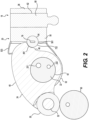
- a Type III valvetrain arrangement is configured to be positioned on a cylinder block (not shown) of an engine.
- a rotating cam 90 is shown schematically and rotating cam 90 can impart a valve lift profile to the rocker arm assembly.
- the valvetrain arrangement is supported in a carrier (not shown) and each cylinder can include an intake valve rocker arm assembly and an exhaust valve rocker arm assembly 18.
- the intake valve rocker arm assembly is configured to control motion of intake valves of an associated engine.
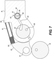
- the latch pin 28 is configured to be moved by an actuator.
- an actuator is shown in Figure 7 .
- Alternative actuators not according to the appended claims can comprise, for example, devices to enable pneumatic, electric, mechanical, etc. movement of the latch pin 28 between an activated position ( FIG. 3A ) and a deactivated position ( FIG. 3B ).
- FIG. 3A activated position
- FIG. 3B deactivated position
- outer arm 26 is configured to transfer motion to another component such as, for example, a valve bridge and/or engine valve.
- the deactivated position rotation of inner arm 24 about rocker shaft 22 does not contact latch pin 28. As such, rotational motion of inner arm 24 is not transferred to outer arm 26.
- inner arm 24 includes a main body 40 having a first aperture 42, and second aperture 44, and a contact arm 46.
- the first aperture 42 is configured to receive rocker shaft 22, and the second aperture 44 is configured to receive pivot pin 32.
- the contact arm 46 is configured to engage the latch pin 28 as by comprising a contact surface 461.
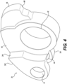
- outer arm 26 includes a main body 50 having opposed flanges 52, a latch bore 54, and a capsule bore 62 (see FIGS. 1 , 2 ).
- the opposed flanges 52 are spaced apart from each other to provide clearance for inner arm 24 to be received therebetween.
- the opposed flanges 52 each define an aperture 58 configured to receive the rocker shaft 22.
- the latch bore 54 is configured to receive the latch pin 28.
- Capsule bore 62 is configured to receive a valve actuation capsule or valve actuation component such as, for example, a switchable capsule 60, hydraulic lash adjuster, mechanical lash adjuster, or spigot, among others, configured to engage an e-foot, valve stem, valve bridge, among others.
- a valve actuation capsule or valve actuation component such as, for example, a switchable capsule 60, hydraulic lash adjuster, mechanical lash adjuster, or spigot, among others, configured to engage an e-foot, valve stem, valve bridge, among others.
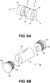
- latch pin 28 includes a generally cylindrical main body 70 having a first end 72 and a second end 74.
- the latch pin 28 is received within the latch bore 54 in an orientation parallel to or substantially parallel to the rocker shaft 22 and transverse to or substantially transverse to a main (longitudinal) axis of the inner and outer arms 24, 26.
- Each end 72, 74 includes a keyway such as a through-hole, recess, or slot 76 configured to receive a key 78 (e.g., see FIG. 3A , 6B ).
- the main body 70 defines a clearance 80 for lost motion of the inner arm 24, such clearance comprising a recess, groove, or notch, for example.
- latch pin 28 In the deactivated position ( FIG. 3B ), latch pin 28 is moved to a position where contact arm 46 is received within, and can alternatively pass through, the clearance 80. In this configuration, inner arm 24 does not transfer motion to outer arm 26 via latch pin 28. The extent of the motion of the contact arm 46 within the clearance 80 is a function of the lift profile transferred from the cam 90.
- latch pin 28 In the activated position ( FIG. 3A ), latch pin 28 is moved to a position where contact arm 46 will contact main body 70 when rotating about rocker shaft 22 to thereby transfer rotational motion to outer arm 26 via the latch pin 28.
- Latch assembly 280, 282 can be configured for use in a switchable rocker arm.
- Latch assembly 280 comprises a key 781 and can comprise a return spring 783 biasing the latch pin 28, while latch assembly 282 can comprise key 781 and second key 782 with the latch pin 28 biased by return springs 781, 782.
- Latch assembly 280, 282 comprises a latch bore 54 formed in a body of material, in this example, in a portion of main body 50 of outer arm 26.
- Latch bore 54 comprises a first bore end 541, a second bore end 542, and a lost motion gap 501.
- Lost motion gap 501 can be formed between shoulders 523, 524 extending from the main body 50 of the outer arm 26. Shoulders 523, 524 can seat biasing mechanisms 91, 92.
- the lost motion gap 501 can be formed by a notch, groove, divot or other indentation that enables the inner arm 24 to move in lost motion.
- Latch pin 28 is configured to reciprocate in the latch bore 54.
- Latch pin 28 comprises a main body 70, which can be cylindrical.
- Latch pin 28 comprises a first plug end 72 in the first bore end 541, a second plug end 74 in the second bore end 542, and a clearance 80 between the first plug end 72 and the second plug end 74.
- the latch pin is configured to selectively move in the latch bore 54 between the activated position and the deactivated position.
- the inner arm 24 in this example, the contact arm 46 and contact surface 461, cannot move in lost motion.
- the inner arm 24 transfers a lift profile from the cam 90 to the valve end of the outer arm 26.
- the latch assembly 280 comprises a key 781 in the latch bore 54.
- the key 781 is configured to guide the latch pin 28 in the latch bore 54.
- the key 781 comprises a post 785 .
- the latch pin 28 comprises a slot 76.
- the key 781 is configured with the post 785 to guide the latch pin 28 via the slot 76.
- the latch bore 54 can be configured with a mating clocking or keying feature, and the key can be substituted with a plug, cap, blind bore, or other latch bore sealing component.
- the key 781 comprises a head 787 that can function to press to the latch bore 54.
- the post 785 extends from the head 787.
- a return spring 783 is coiled around the post 78 and is biased against the head 787 and the first plug end 72 to bias the latch pin 28 in the latch bore 54.
- the return spring 783 can push the plug body 721 so that it blocks the inner arm 24 from moving in the lost motion gap 501. If a blind bore were placed at the second bore end 542, a hydraulic supply pressure could be controlled to opposed the force of the return spring 783 to push the clearance 80 into alignment with the lost motion gap 501. Hydraulic supply pressure could be supplied via supply port 221 in rocker shaft 22.
- a second supply port 222 can function as another pressure control conduit, including a return path.
- controlling hydraulic supply pressures is supplied to both ends 541, 542 of the latch bore.
- two hydraulic ports 521, 522 can extend in the flanges 52 and in the main body 50 between the rocker shaft 22 and the latch bore 54 so that oil pressure control can direct the latch pin 28 between the deactivated and activation positions.
- Hydraulic supply pressure could be supplied via control of the positions of supply ports 221, 222 in rocker shaft 22.
- the latch bore 54 is configured to receive hydraulic control via one or more hydraulic ports 521, 522 in one or both of the first bore end 541 and the second bore end 542 to move the latch pin 28. Having a plug shape to the plug bodies 721, 722 allows pressure to build against the latch pin 28 for oil control. But, with modification to the latch pin 28 and latch bore, other reciprocation control techniques can be achieved.
- the latch assembly 282 can comprise a second return spring 784 biased against the second plug end 74.
- a rim, lip, post, stake, or other spring guide can optionally be included in the latch bore 54.
- a through-hole can be used at the second bore end 542.
- Second key 782 can be pressed to the through-hole to secure the latch pin 28 in the latch bore 54.
- Second key 782, and its alternatives, can comprise any one of the alternatives that key 781 can comprise, including head 788 & post 786.
- Second return spring 784 can bias against the second plug end 74 and the head 788 of second key 782.
- a rocker arm assembly 18 can comprise an outer arm 26 configured to rotate about a rocker shaft 22.
- Outer arm 26 can comprise main body 50 defining opposed flanges 52 each defining an aperture (rocker bore) 58 to receive the rocker shaft 22.
- the outer arm 26 can comprise the latch bore 54.
- the latch bore 54 can be between the rocker shaft 22 and the valve end.
- the valve end can comprise a cleat, e-foot, or other structure to couple to a valve or valve bridge, or valve end can comprise a capsule 60 such as a lost motion capsule, engine braking capsule, among others.
- Inner arm 24 can be at least partially disposed within the outer arm 26 and can be configured to selectively move within the outer arm 26. While the inner arm 24 is illustrated as rotating about the rocker shaft 22 as by surrounding the rocker shaft 22 with first aperture (rocker bore) 42, other pivot locations can be had, as by including a pivot pin to link the inner arm 24 to the outer arm 26. The inner arm 24 can rotate relative to the rocker shaft 22 via these alternative pivot arrangements.
- the latch assembly 280, 282 can be positioned to move between the activated position and the deactivated position, as by reciprocating in the latch bore 54.
- the inner arm 24 is configured to transfer force to the outer arm 26 via the latch pin 28.
- the inner arm 24 is configured to move in the clearance 80 and in the lost motion gap 501.
- the inner arm can comprise a main body 40 defining a first aperture (rocker bore) 42 to receive the rocker shaft 22.
- a second aperture or pair of apertures 44 can be formed across a forked roller end 241 and can be configured to rotatably support a roller 30.
- Roller 30 can be seated via a pivot pin 32.
- roller 30 can be substituted with a tappet. Tappet or roller can be configured to receive a lift profile from cam 90.
- Inner arm 24 can also comprise a contact arm 46 configured to selectively contact the latch pin 28 when the latch pin is in the activated position.
- the contact arm 46 can comprise a contoured contact surface 461 to distribute pressure on the latch pin 28.
- One or more biasing mechanisms 91, 92 can be disposed between the inner arm 24 and the outer arm 26 to bias the inner and outer arms into a desired position relative to each other.
- the rocker arm assembly includes an inner arm, outer arm, and latch pin designed for high stiffness and low mass moment of inertia.
- the design is configured to provide no contact stress singularity issues at edges of the latch pin/rocker arm hole ID due to tangent/throughout contact of the latch pin maintained with the rocker arm hole.
- the inner arm, outer arm, and latch pin are designed to reduce tensile stress to provide improved fatigue life. Additional modifications can provide further improvement to assembly stiffness.
Landscapes
- Engineering & Computer Science (AREA)
- Mechanical Engineering (AREA)
- General Engineering & Computer Science (AREA)
- Valve Device For Special Equipments (AREA)
Claims (12)
- Verriegelungsanordnung (280; 282) für einen schaltbaren Kipphebel (20), aufweisend:eine Verriegelungsbohrung (54), die ein erstes Bohrungsende (541), ein zweites Bohrungsende (542) und einen Totgangspalt (501) aufweist;einen Verriegelungsstift (28), der konfiguriert ist, um sich in der Verriegelungsbohrung (54) hin- und herzubewegen, wobei der Verriegelungsstift (28) einen Hauptkörper (70) aufweist, der ein erstes Steckerende (72) in dem ersten Bohrungsende (541), ein zweites Steckerende (74) in dem zweiten Bohrungsende (542) und einen Zwischenraum (80) zwischen dem ersten Steckerende (72) und dem zweiten Steckerende (74) aufweist, wobei der Verriegelungsstift (28) konfiguriert ist, um sich selektiv in der Verriegelungsbohrung (54) zwischen einer aktivierten Position und einer deaktivierten Position zu bewegen, wobei, wenn sich der Verriegelungsstift (28) in der aktivierten Position befindet, entweder das erste Steckerende (72) oder das zweite Steckerende (74) in dem Totgangspalt (501) positioniert ist, und wobei, wenn sich der Verriegelungsstift (28) in der deaktivierten Position befindet, der Zwischenraum (80) in dem Totgangspalt (501) ist;einen Schlüssel (781) in der Verriegelungsbohrung (54), wobei der Schlüssel konfiguriert ist, um den Verriegelungsstift (28) in der Verriegelungsbohrung (54) zu führen, wobei der Schlüssel (781) einen Stift (785) aufweist, wobei der Verriegelungsstift (28) einen Schlitz (76) aufweist, und wobei der Schlüssel (781) den Verriegelungsstift (28) über den Schlitz (76) führt, undwobei die Verriegelungsbohrung (54) konfiguriert ist, um sowohl am ersten Bohrungsende (541) als auch am zweiten Bohrungsende (542) eine hydraulische Steuerung aufzunehmen, um den Verriegelungsstift (28) zu bewegen.
- Verriegelungsanordnung (280; 282) nach Anspruch 1, ferner aufweisend eine Rückstellfeder (783), die konfiguriert ist, um den Verriegelungsstift (28) in der Verriegelungsbohrung (54) vorzuspannen.
- Verriegelungsanordnung (280; 282) nach Anspruch 1, ferner aufweisend eine zweite Rückstellfeder (784), wobei die Rückstellfeder (783) gegen das erste Steckerende (72) vorgespannt ist und wobei die zweite Rückstellfeder (784) gegen das zweite Steckerende (74) vorgespannt ist.
- Kipphebelanordnung (18), aufweisend:die Verriegelungsanordnung (280; 282) nach Anspruch 1, aufweisend den Verriegelungsstift (28), der zwischen der aktivierten Position und der deaktivierten Position bewegbar ist,einen äußeren Arm (26), der konfiguriert ist, um sich um eine Kipphebelwelle (22) zu drehen, wobei der äußere Arm die Verriegelungsbohrung (54) aufweist;einen inneren Arm (24), der zumindest teilweise innerhalb des äußeren Arms (26) angeordnet ist und konfiguriert ist, um sich selektiv innerhalb des äußeren Arms zu bewegen;wobei der innere Arm (24) konfiguriert ist, um Kraft auf den äußeren Arm (26) über den Verriegelungsstift zu übertragen, wenn sich der Verriegelungsstift (28) in der aktivierten Position befindet, und wobei der innere Arm (24) konfiguriert ist, um sich in dem Zwischenraum (80) und in dem Totgangspalt (501) zu bewegen, wenn sich der Verriegelungsstift (28) in der deaktivierten Position befindet.
- Kipphebelanordnung nach Anspruch 4, wobei der innere Arm (24) einen Hauptkörper (40) aufweist, der Folgendes definiert:eine erste Öffnung (42) zum Aufnehmen der Kipphebelwelle (22);eine zweite Öffnung (44), die konfiguriert ist, um eine Rolle (30) drehbar zu lagern; undeinen Kontaktarm (46), der konfiguriert ist, um selektiv den Verriegelungsstift (28) zu berühren, wenn sich der Verriegelungsstift in der aktivierten Position befindet.
- Kipphebelanordnung nach Anspruch 5, wobei die Rolle (30) konfiguriert ist, um ein Hubprofil von einem Nocken (90) aufzunehmen.
- Kipphebelanordnung nach Anspruch 4, wobei der äußere Arm (26) einen Hauptkörper (50) aufweist, der Folgendes definiert:gegenüberliegende Flansche (52), die jeweils eine Öffnung (58) definieren, um die Kipphebelwelle (22) aufzunehmen;die Verriegelungsbohrung (54), die konfiguriert ist, um den Verriegelungsstift (28) aufzunehmen; undeine Kapselbohrung (62), die konfiguriert ist, um eine Ventilbetätigungskapsel (60) aufzunehmen.
- Kipphebelanordnung nach Anspruch 7, ferner aufweisend einen Hydraulikanschluss (521, 522) in mindestens einem der gegenüberliegenden Flansche (52), wobei der Hydraulikanschluss konfiguriert ist, um ein Betätigungsfluid von der Kipphebelwelle (22) zu der Verriegelungsbohrung (54) zuzuführen.
- Kipphebelanordnung nach Anspruch 4, wobei das erste Bohrungsende (541) ein Durchgangsloch aufweist, wobei das zweite Bohrungsende (542) ein Sackloch aufweist, und wobei die Verriegelungsanordnung ferner den in das Durchgangsloch eingepassten Schlüssel (781) aufweist, um den Verriegelungsstift (28) in der Verriegelungsbohrung (54) zu halten.
- Kipphebelanordnung nach Anspruch 4, wobei das erste Bohrungsende (541) ein Durchgangsloch aufweist, wobei das zweite Bohrungsende (542) ein zweites Durchgangsloch aufweist, und wobei die Verriegelungsanordnung ferner aufweist:den Schlüssel (781), der in das Durchgangsloch eingepasst ist, um den Verriegelungsstift (28) in der Verriegelungsbohrung (54) zu halten; undeinen zweiten Schlüssel (782), der in das zweite Durchgangsloch eingepasst ist, um den Verriegelungsstift (28) in der Verriegelungsbohrung (54) zu halten.
- Kipphebelanordnung nach Anspruch 9 oder 10, wobei der Schlüssel (781) einen ersten Stift (785) aufweist, wobei das erste Steckerende (72) einen ersten Schlitz (76) aufweist, der konfiguriert ist, um sich auf dem ersten Stift hin- und herzubewegen.
- Kipphebelanordnung nach Anspruch 4, wobei der Verriegelungsstift (28) einen Hauptkörper (70) aufweist, der Folgendes definiert:Das erste Steckerende (72) und das zweite Steckerende (74), die jeweils einen Schlitz (76) definieren, der konfiguriert ist, um einen jeweiligen Schlüssel (781) aufzunehmen, und einen zweiten Schlüssel (782), der konfiguriert ist, um den Verriegelungsstift (28) zu führen; undden Zwischenraum (80), der konfiguriert ist, um dem inneren Arm (24) zu ermöglichen, sich darin zu bewegen, wenn sich der Verriegelungsstift (28) in der deaktivierten Position befindet,wobei, wenn sich der Verriegelungsstift (28) in der aktivierten Position befindet, der innere Arm (24) konfiguriert ist, um den Verriegelungsstift-Hauptkörper (70) zu berühren, um dem äußeren Arm (26) über den Verriegelungsstift (28) eine Bewegung zu verleihen.
Applications Claiming Priority (2)
| Application Number | Priority Date | Filing Date | Title |
|---|---|---|---|
| IN202011002040 | 2020-01-16 | ||
| PCT/EP2021/025009 WO2021144148A1 (en) | 2020-01-16 | 2021-01-15 | Latch assembly and compact rocker arm assembly |
Publications (2)
| Publication Number | Publication Date |
|---|---|
| EP4090838A1 EP4090838A1 (de) | 2022-11-23 |
| EP4090838B1 true EP4090838B1 (de) | 2025-02-26 |
Family
ID=74205803
Family Applications (1)
| Application Number | Title | Priority Date | Filing Date |
|---|---|---|---|
| EP21701209.5A Active EP4090838B1 (de) | 2020-01-16 | 2021-01-15 | Verriegelungsvorrichtung und kompakte kipphebelanordnung |
Country Status (4)
| Country | Link |
|---|---|
| US (1) | US11828205B2 (de) |
| EP (1) | EP4090838B1 (de) |
| CN (1) | CN114846223B (de) |
| WO (1) | WO2021144148A1 (de) |
Families Citing this family (1)
| Publication number | Priority date | Publication date | Assignee | Title |
|---|---|---|---|---|
| CN117569889A (zh) * | 2020-02-19 | 2024-02-20 | 伊顿智能动力有限公司 | 摇臂组件 |
Family Cites Families (15)
| Publication number | Priority date | Publication date | Assignee | Title |
|---|---|---|---|---|
| US5544626A (en) * | 1995-03-09 | 1996-08-13 | Ford Motor Company | Finger follower rocker arm with engine valve deactivator |
| DE10060890C2 (de) * | 2000-12-07 | 2003-04-03 | Meta Motoren Energietech | Vorrichtung zum Umschalten des Betriebs eines Ladungswechselventils einer Brennkraftmaschine |
| US20050188930A1 (en) * | 2004-02-18 | 2005-09-01 | Best Richard R. | Valve deactivation device |
| WO2005093224A1 (en) | 2004-03-03 | 2005-10-06 | Timken Us Corporation | Switching finger follower assembly |
| US7121241B1 (en) | 2006-01-10 | 2006-10-17 | Eaton Corporation | Valve control system including deactivating rocker arm |
| CN203640793U (zh) * | 2013-12-30 | 2014-06-11 | 绵阳富临精工机械股份有限公司 | 一种发动机气门双升程摇臂 |
| CN204041146U (zh) | 2014-09-11 | 2014-12-24 | 绵阳富临精工机械股份有限公司 | 一种气门升程控制压杆 |
| US9976493B2 (en) * | 2016-04-01 | 2018-05-22 | Schaoffler Technologies AG & Co. KG | Switchable rocker arm with reduced coupling assembly loads |
| WO2018068041A1 (en) | 2016-10-07 | 2018-04-12 | Eaton Corporation | Three roller rocker arm with cantilevered rollers and lost motion spring over valve or over rocker arm pivot |
| GB201703793D0 (en) | 2017-03-09 | 2017-04-26 | Eaton Srl | Switchable rocker arm |
| WO2018217536A2 (en) | 2017-05-23 | 2018-11-29 | Eaton Intelligent Power Limited | Magnetic actuator for switching roller finger followers |
| US10605126B2 (en) * | 2018-04-17 | 2020-03-31 | Delphi Technologies Ip Limited | Switchable rocker arm |
| US10533463B1 (en) | 2018-09-06 | 2020-01-14 | Delphi Technologies Ip Limited | Switchable rocker arm and roller retainer thereof |
| US10781729B1 (en) * | 2019-05-09 | 2020-09-22 | Schaeffler Technologies AG & Co. KG | Switchable rocker arm |
| JP7302018B2 (ja) | 2019-05-28 | 2023-07-03 | ジェイコブス ビークル システムズ、インコーポレイテッド | ローブ切り替え式と単一源のロストモーション用フィンガフォロワ |
-
2021
- 2021-01-15 EP EP21701209.5A patent/EP4090838B1/de active Active
- 2021-01-15 WO PCT/EP2021/025009 patent/WO2021144148A1/en not_active Ceased
- 2021-01-15 CN CN202180007535.XA patent/CN114846223B/zh active Active
- 2021-01-15 US US17/758,640 patent/US11828205B2/en active Active
Also Published As
| Publication number | Publication date |
|---|---|
| US20230042443A1 (en) | 2023-02-09 |
| CN114846223A (zh) | 2022-08-02 |
| WO2021144148A1 (en) | 2021-07-22 |
| CN114846223B (zh) | 2023-10-27 |
| EP4090838A1 (de) | 2022-11-23 |
| US11828205B2 (en) | 2023-11-28 |
Similar Documents
| Publication | Publication Date | Title |
|---|---|---|
| EP1725744B1 (de) | Schaltschlepphebelanordnung | |
| US6691657B2 (en) | Two-step finger follower rocker arm | |
| US6668779B2 (en) | Two-step finger follower rocker arm assembly | |
| CN110832173B (zh) | 活塞式内燃机的可变气门传动机构 | |
| EP1462623A1 (de) | Ventilsteuersystem zur Einstellung zweier Ventilhübe und zur Ventilabschaltung | |
| EP3620624B1 (de) | Schaltbarer kipphebel und rollenhalter dafür | |
| US7201125B2 (en) | Valve train for an internal combustion engine | |
| EP3289190A1 (de) | Armanordnung einer schaltwippe mit exzenterachse zur spieleinstellung | |
| US7093572B2 (en) | Roller finger follower assembly for valve deactivation | |
| CN115667676A (zh) | 摇臂 | |
| CN111836948B (zh) | 摇臂控制系统 | |
| JPS62253913A (ja) | 自動車用エンジンにおけるバルブ停止装置 | |
| EP4090838B1 (de) | Verriegelungsvorrichtung und kompakte kipphebelanordnung | |
| CN117642550A (zh) | 具有主摇杆和分叉辅助摇杆的摇臂组件 | |
| US9920659B2 (en) | Coupling pin anti-rotation for a switchable roller finger follower | |
| EP3628832A1 (de) | Schaltbarer kipphebel | |
| EP3620623A1 (de) | Schaltbarer kipphebel und rollenhalter dafür | |
| US10871087B2 (en) | Switchable rocker arm | |
| US20170122135A1 (en) | Method for setting lash in a mechanically lashed valvetrain having a switching rocker arm | |
| US20210396164A1 (en) | Type iii cam side cylinder deactivation | |
| KR20240011819A (ko) | 로브 스위칭 및 단일 소스 손실 모션을 위한 핑거 팔로워를 포함하는 밸브 구동 시스템 | |
| MXPA96001186A (en) | Valv control system |
Legal Events
| Date | Code | Title | Description |
|---|---|---|---|
| STAA | Information on the status of an ep patent application or granted ep patent |
Free format text: STATUS: UNKNOWN |
|
| STAA | Information on the status of an ep patent application or granted ep patent |
Free format text: STATUS: THE INTERNATIONAL PUBLICATION HAS BEEN MADE |
|
| PUAI | Public reference made under article 153(3) epc to a published international application that has entered the european phase |
Free format text: ORIGINAL CODE: 0009012 |
|
| STAA | Information on the status of an ep patent application or granted ep patent |
Free format text: STATUS: REQUEST FOR EXAMINATION WAS MADE |
|
| 17P | Request for examination filed |
Effective date: 20220802 |
|
| AK | Designated contracting states |
Kind code of ref document: A1 Designated state(s): AL AT BE BG CH CY CZ DE DK EE ES FI FR GB GR HR HU IE IS IT LI LT LU LV MC MK MT NL NO PL PT RO RS SE SI SK SM TR |
|
| DAV | Request for validation of the european patent (deleted) | ||
| DAX | Request for extension of the european patent (deleted) | ||
| P01 | Opt-out of the competence of the unified patent court (upc) registered |
Effective date: 20230521 |
|
| GRAP | Despatch of communication of intention to grant a patent |
Free format text: ORIGINAL CODE: EPIDOSNIGR1 |
|
| STAA | Information on the status of an ep patent application or granted ep patent |
Free format text: STATUS: GRANT OF PATENT IS INTENDED |
|
| INTG | Intention to grant announced |
Effective date: 20240920 |
|
| GRAS | Grant fee paid |
Free format text: ORIGINAL CODE: EPIDOSNIGR3 |
|
| GRAA | (expected) grant |
Free format text: ORIGINAL CODE: 0009210 |
|
| STAA | Information on the status of an ep patent application or granted ep patent |
Free format text: STATUS: THE PATENT HAS BEEN GRANTED |
|
| AK | Designated contracting states |
Kind code of ref document: B1 Designated state(s): AL AT BE BG CH CY CZ DE DK EE ES FI FR GB GR HR HU IE IS IT LI LT LU LV MC MK MT NL NO PL PT RO RS SE SI SK SM TR |
|
| REG | Reference to a national code |
Ref country code: GB Ref legal event code: FG4D |
|
| REG | Reference to a national code |
Ref country code: CH Ref legal event code: EP |
|
| REG | Reference to a national code |
Ref country code: DE Ref legal event code: R096 Ref document number: 602021026735 Country of ref document: DE |
|
| REG | Reference to a national code |
Ref country code: IE Ref legal event code: FG4D |
|
| REG | Reference to a national code |
Ref country code: NL Ref legal event code: MP Effective date: 20250226 |
|
| PG25 | Lapsed in a contracting state [announced via postgrant information from national office to epo] |
Ref country code: RS Free format text: LAPSE BECAUSE OF FAILURE TO SUBMIT A TRANSLATION OF THE DESCRIPTION OR TO PAY THE FEE WITHIN THE PRESCRIBED TIME-LIMIT Effective date: 20250526 |
|
| PG25 | Lapsed in a contracting state [announced via postgrant information from national office to epo] |
Ref country code: FI Free format text: LAPSE BECAUSE OF FAILURE TO SUBMIT A TRANSLATION OF THE DESCRIPTION OR TO PAY THE FEE WITHIN THE PRESCRIBED TIME-LIMIT Effective date: 20250226 |
|
| PG25 | Lapsed in a contracting state [announced via postgrant information from national office to epo] |
Ref country code: PL Free format text: LAPSE BECAUSE OF FAILURE TO SUBMIT A TRANSLATION OF THE DESCRIPTION OR TO PAY THE FEE WITHIN THE PRESCRIBED TIME-LIMIT Effective date: 20250226 |
|
| PG25 | Lapsed in a contracting state [announced via postgrant information from national office to epo] |
Ref country code: ES Free format text: LAPSE BECAUSE OF FAILURE TO SUBMIT A TRANSLATION OF THE DESCRIPTION OR TO PAY THE FEE WITHIN THE PRESCRIBED TIME-LIMIT Effective date: 20250226 |
|
| REG | Reference to a national code |
Ref country code: LT Ref legal event code: MG9D |
|
| PG25 | Lapsed in a contracting state [announced via postgrant information from national office to epo] |
Ref country code: NO Free format text: LAPSE BECAUSE OF FAILURE TO SUBMIT A TRANSLATION OF THE DESCRIPTION OR TO PAY THE FEE WITHIN THE PRESCRIBED TIME-LIMIT Effective date: 20250526 Ref country code: IS Free format text: LAPSE BECAUSE OF FAILURE TO SUBMIT A TRANSLATION OF THE DESCRIPTION OR TO PAY THE FEE WITHIN THE PRESCRIBED TIME-LIMIT Effective date: 20250626 |
|
| PG25 | Lapsed in a contracting state [announced via postgrant information from national office to epo] |
Ref country code: NL Free format text: LAPSE BECAUSE OF FAILURE TO SUBMIT A TRANSLATION OF THE DESCRIPTION OR TO PAY THE FEE WITHIN THE PRESCRIBED TIME-LIMIT Effective date: 20250226 |
|
| PG25 | Lapsed in a contracting state [announced via postgrant information from national office to epo] |
Ref country code: HR Free format text: LAPSE BECAUSE OF FAILURE TO SUBMIT A TRANSLATION OF THE DESCRIPTION OR TO PAY THE FEE WITHIN THE PRESCRIBED TIME-LIMIT Effective date: 20250226 |
|
| PG25 | Lapsed in a contracting state [announced via postgrant information from national office to epo] |
Ref country code: LV Free format text: LAPSE BECAUSE OF FAILURE TO SUBMIT A TRANSLATION OF THE DESCRIPTION OR TO PAY THE FEE WITHIN THE PRESCRIBED TIME-LIMIT Effective date: 20250226 Ref country code: PT Free format text: LAPSE BECAUSE OF FAILURE TO SUBMIT A TRANSLATION OF THE DESCRIPTION OR TO PAY THE FEE WITHIN THE PRESCRIBED TIME-LIMIT Effective date: 20250626 |
|
| PG25 | Lapsed in a contracting state [announced via postgrant information from national office to epo] |
Ref country code: GR Free format text: LAPSE BECAUSE OF FAILURE TO SUBMIT A TRANSLATION OF THE DESCRIPTION OR TO PAY THE FEE WITHIN THE PRESCRIBED TIME-LIMIT Effective date: 20250527 Ref country code: BG Free format text: LAPSE BECAUSE OF FAILURE TO SUBMIT A TRANSLATION OF THE DESCRIPTION OR TO PAY THE FEE WITHIN THE PRESCRIBED TIME-LIMIT Effective date: 20250226 |
|
| REG | Reference to a national code |
Ref country code: AT Ref legal event code: MK05 Ref document number: 1770799 Country of ref document: AT Kind code of ref document: T Effective date: 20250226 |
|
| PG25 | Lapsed in a contracting state [announced via postgrant information from national office to epo] |
Ref country code: SE Free format text: LAPSE BECAUSE OF FAILURE TO SUBMIT A TRANSLATION OF THE DESCRIPTION OR TO PAY THE FEE WITHIN THE PRESCRIBED TIME-LIMIT Effective date: 20250226 |
|
| PG25 | Lapsed in a contracting state [announced via postgrant information from national office to epo] |
Ref country code: SM Free format text: LAPSE BECAUSE OF FAILURE TO SUBMIT A TRANSLATION OF THE DESCRIPTION OR TO PAY THE FEE WITHIN THE PRESCRIBED TIME-LIMIT Effective date: 20250226 |
|
| PG25 | Lapsed in a contracting state [announced via postgrant information from national office to epo] |
Ref country code: DK Free format text: LAPSE BECAUSE OF FAILURE TO SUBMIT A TRANSLATION OF THE DESCRIPTION OR TO PAY THE FEE WITHIN THE PRESCRIBED TIME-LIMIT Effective date: 20250226 |
|
| PG25 | Lapsed in a contracting state [announced via postgrant information from national office to epo] |
Ref country code: IT Free format text: LAPSE BECAUSE OF FAILURE TO SUBMIT A TRANSLATION OF THE DESCRIPTION OR TO PAY THE FEE WITHIN THE PRESCRIBED TIME-LIMIT Effective date: 20250226 |
|
| PG25 | Lapsed in a contracting state [announced via postgrant information from national office to epo] |
Ref country code: AT Free format text: LAPSE BECAUSE OF FAILURE TO SUBMIT A TRANSLATION OF THE DESCRIPTION OR TO PAY THE FEE WITHIN THE PRESCRIBED TIME-LIMIT Effective date: 20250226 |
|
| PG25 | Lapsed in a contracting state [announced via postgrant information from national office to epo] |
Ref country code: CZ Free format text: LAPSE BECAUSE OF FAILURE TO SUBMIT A TRANSLATION OF THE DESCRIPTION OR TO PAY THE FEE WITHIN THE PRESCRIBED TIME-LIMIT Effective date: 20250226 Ref country code: EE Free format text: LAPSE BECAUSE OF FAILURE TO SUBMIT A TRANSLATION OF THE DESCRIPTION OR TO PAY THE FEE WITHIN THE PRESCRIBED TIME-LIMIT Effective date: 20250226 |
|
| PG25 | Lapsed in a contracting state [announced via postgrant information from national office to epo] |
Ref country code: RO Free format text: LAPSE BECAUSE OF FAILURE TO SUBMIT A TRANSLATION OF THE DESCRIPTION OR TO PAY THE FEE WITHIN THE PRESCRIBED TIME-LIMIT Effective date: 20250226 |
|
| PG25 | Lapsed in a contracting state [announced via postgrant information from national office to epo] |
Ref country code: SK Free format text: LAPSE BECAUSE OF FAILURE TO SUBMIT A TRANSLATION OF THE DESCRIPTION OR TO PAY THE FEE WITHIN THE PRESCRIBED TIME-LIMIT Effective date: 20250226 |
|
| REG | Reference to a national code |
Ref country code: DE Ref legal event code: R097 Ref document number: 602021026735 Country of ref document: DE |
|
| PLBE | No opposition filed within time limit |
Free format text: ORIGINAL CODE: 0009261 |
|
| STAA | Information on the status of an ep patent application or granted ep patent |
Free format text: STATUS: NO OPPOSITION FILED WITHIN TIME LIMIT |
|
| 26N | No opposition filed |
Effective date: 20251127 |
|
| PGFP | Annual fee paid to national office [announced via postgrant information from national office to epo] |
Ref country code: DE Payment date: 20251217 Year of fee payment: 6 |