US10605126B2 - Switchable rocker arm - Google Patents
Switchable rocker arm Download PDFInfo
- Publication number
- US10605126B2 US10605126B2 US15/955,215 US201815955215A US10605126B2 US 10605126 B2 US10605126 B2 US 10605126B2 US 201815955215 A US201815955215 A US 201815955215A US 10605126 B2 US10605126 B2 US 10605126B2
- Authority
- US
- United States
- Prior art keywords
- lock pin
- arm
- rocker arm
- bore
- inner arm
- Prior art date
- Legal status (The legal status is an assumption and is not a legal conclusion. Google has not performed a legal analysis and makes no representation as to the accuracy of the status listed.)
- Active, expires
Links
Images


Classifications
-
- F—MECHANICAL ENGINEERING; LIGHTING; HEATING; WEAPONS; BLASTING
- F01—MACHINES OR ENGINES IN GENERAL; ENGINE PLANTS IN GENERAL; STEAM ENGINES
- F01L—CYCLICALLY OPERATING VALVES FOR MACHINES OR ENGINES
- F01L1/00—Valve-gear or valve arrangements, e.g. lift-valve gear
- F01L1/20—Adjusting or compensating clearance
- F01L1/22—Adjusting or compensating clearance automatically, e.g. mechanically
-
- F—MECHANICAL ENGINEERING; LIGHTING; HEATING; WEAPONS; BLASTING
- F01—MACHINES OR ENGINES IN GENERAL; ENGINE PLANTS IN GENERAL; STEAM ENGINES
- F01L—CYCLICALLY OPERATING VALVES FOR MACHINES OR ENGINES
- F01L13/00—Modifications of valve-gear to facilitate reversing, braking, starting, changing compression ratio, or other specific operations
- F01L13/0005—Deactivating valves
-
- F—MECHANICAL ENGINEERING; LIGHTING; HEATING; WEAPONS; BLASTING
- F01—MACHINES OR ENGINES IN GENERAL; ENGINE PLANTS IN GENERAL; STEAM ENGINES
- F01L—CYCLICALLY OPERATING VALVES FOR MACHINES OR ENGINES
- F01L1/00—Valve-gear or valve arrangements, e.g. lift-valve gear
- F01L1/02—Valve drive
- F01L1/04—Valve drive by means of cams, camshafts, cam discs, eccentrics or the like
- F01L1/047—Camshafts
-
- F—MECHANICAL ENGINEERING; LIGHTING; HEATING; WEAPONS; BLASTING
- F01—MACHINES OR ENGINES IN GENERAL; ENGINE PLANTS IN GENERAL; STEAM ENGINES
- F01L—CYCLICALLY OPERATING VALVES FOR MACHINES OR ENGINES
- F01L1/00—Valve-gear or valve arrangements, e.g. lift-valve gear
- F01L1/12—Transmitting gear between valve drive and valve
- F01L1/18—Rocking arms or levers
- F01L1/181—Centre pivot rocking arms
- F01L1/182—Centre pivot rocking arms the rocking arm being pivoted about an individual fulcrum, i.e. not about a common shaft
-
- F—MECHANICAL ENGINEERING; LIGHTING; HEATING; WEAPONS; BLASTING
- F01—MACHINES OR ENGINES IN GENERAL; ENGINE PLANTS IN GENERAL; STEAM ENGINES
- F01L—CYCLICALLY OPERATING VALVES FOR MACHINES OR ENGINES
- F01L1/00—Valve-gear or valve arrangements, e.g. lift-valve gear
- F01L1/12—Transmitting gear between valve drive and valve
- F01L1/18—Rocking arms or levers
- F01L1/185—Overhead end-pivot rocking arms
-
- F—MECHANICAL ENGINEERING; LIGHTING; HEATING; WEAPONS; BLASTING
- F01—MACHINES OR ENGINES IN GENERAL; ENGINE PLANTS IN GENERAL; STEAM ENGINES
- F01L—CYCLICALLY OPERATING VALVES FOR MACHINES OR ENGINES
- F01L13/00—Modifications of valve-gear to facilitate reversing, braking, starting, changing compression ratio, or other specific operations
- F01L13/0015—Modifications of valve-gear to facilitate reversing, braking, starting, changing compression ratio, or other specific operations for optimising engine performances by modifying valve lift according to various working parameters, e.g. rotational speed, load, torque
- F01L13/0036—Modifications of valve-gear to facilitate reversing, braking, starting, changing compression ratio, or other specific operations for optimising engine performances by modifying valve lift according to various working parameters, e.g. rotational speed, load, torque the valves being driven by two or more cams with different shape, size or timing or a single cam profiled in axial and radial direction
-
- F—MECHANICAL ENGINEERING; LIGHTING; HEATING; WEAPONS; BLASTING
- F01—MACHINES OR ENGINES IN GENERAL; ENGINE PLANTS IN GENERAL; STEAM ENGINES
- F01L—CYCLICALLY OPERATING VALVES FOR MACHINES OR ENGINES
- F01L1/00—Valve-gear or valve arrangements, e.g. lift-valve gear
- F01L1/12—Transmitting gear between valve drive and valve
- F01L1/18—Rocking arms or levers
- F01L2001/186—Split rocking arms, e.g. rocker arms having two articulated parts and means for varying the relative position of these parts or for selectively connecting the parts to move in unison
-
- F—MECHANICAL ENGINEERING; LIGHTING; HEATING; WEAPONS; BLASTING
- F01—MACHINES OR ENGINES IN GENERAL; ENGINE PLANTS IN GENERAL; STEAM ENGINES
- F01L—CYCLICALLY OPERATING VALVES FOR MACHINES OR ENGINES
- F01L1/00—Valve-gear or valve arrangements, e.g. lift-valve gear
- F01L1/46—Component parts, details, or accessories, not provided for in preceding subgroups
- F01L2001/467—Lost motion springs
-
- F—MECHANICAL ENGINEERING; LIGHTING; HEATING; WEAPONS; BLASTING
- F01—MACHINES OR ENGINES IN GENERAL; ENGINE PLANTS IN GENERAL; STEAM ENGINES
- F01L—CYCLICALLY OPERATING VALVES FOR MACHINES OR ENGINES
- F01L13/00—Modifications of valve-gear to facilitate reversing, braking, starting, changing compression ratio, or other specific operations
- F01L2013/10—Auxiliary actuators for variable valve timing
- F01L2013/101—Electromagnets
-
- F01L2105/00—
-
- F—MECHANICAL ENGINEERING; LIGHTING; HEATING; WEAPONS; BLASTING
- F01—MACHINES OR ENGINES IN GENERAL; ENGINE PLANTS IN GENERAL; STEAM ENGINES
- F01L—CYCLICALLY OPERATING VALVES FOR MACHINES OR ENGINES
- F01L2305/00—Valve arrangements comprising rollers
Definitions
- the present invention relates to a rocker arm for valve train of an internal combustion engine; more particularly to a rocker arm with an inner arm which selectively pivots relative to an outer arm, and even more particularly to such a rocker arm with a lock pin which is moved between a coupled position and an uncoupled position.
- Variable valve actuation mechanisms for internal combustion engines are well known. It is known to lower the lift, or even to provide no lift at all, of one or more valves of an internal combustion engine, during periods of light engine load. Such valve deactivation or valve lift switching can substantially improve one or more of fuel efficiency, emissions, and engine performance.
- a rocker arm acts between a rotating eccentric camshaft lobe and a pivot point on the internal combustion engine, such as a hydraulic lash adjuster, to open and close an engine valve.
- Switchable rocker arms may be a “deactivation” type or a “two-step” type.
- the term switchable deactivation rocker arm means the switchable rocker arm is capable of switching from a valve lift mode to a no lift mode.
- the term switchable two-step rocker arm means the switchable rocker arm is capable of switching from a first valve lift mode to a second and lesser valve lift mode, that is greater than no lift. It should be noted that the second valve lift mode may provide one or both of decreased lift magnitude and decreased lift duration of the engine valve compared to the first valve lift mode.
- switchable rocker arm is used herein, by itself, it includes both types.
- a typical switchable rocker arm includes an outer arm and an inner arm.
- the inner arm is movably connected to the outer arm. It can be switched by a locking member, from a coupled mode wherein the inner arm is immobilized relative to the outer arm, to a decoupled mode wherein the inner arm can move relative to the outer arm.
- the outer arm of the switchable rocker arm is pivotally supported at a first end by the hydraulic lash adjuster.
- a second end of the outer arm operates against an associated engine valve for opening and closing the valve by the rotation of an associated eccentric cam lobe acting on an inner arm contact surface which may be a roller.
- the inner arm is connected to the outer arm for pivotal movement about the outer arm's second end with the contact surface of the inner arm disposed between the first and second ends of the outer arm.
- the locking member includes a locking pin disposed in a bore in the first end of the outer arm, the locking pin being selectively moved to engage the inner arm to thereby couple the inner arm to the outer arm when engaged, and decouple the inner arm from the outer arm when disengaged.
- the outer arm In a switchable two-step rocker arm, the outer arm typically supports a pair of rollers carried by a shaft. The rollers are positioned to be engaged by associated low-lift eccentric cam lobes that cause the outer arm to pivot about the hydraulic lash adjuster, thereby actuating an associated engine valve to a low-lift.
- the inner arm In turn, is positioned to engage an associated high-lift eccentric cam lobe sandwiched between the aforementioned low-lift lobes.
- the switchable two-step rocker arm is then selectively switched between a coupled and a decoupled mode by the locking member.
- the rotational movement of the central high-lift lobe is transferred from the inner arm, through the outer arm to cause pivotal movement of the rocker arm about the hydraulic lash adjuster, which in turn opens the associated valve to a high-lift.
- the inner arm is no longer locked to the outer arm and is permitted to move relative to the outer arm against a lost motion spring that biases the inner arm away from the outer arm.
- the rollers of the outer arm engage their associated low-lift lobes.
- the rotational movement of the low-lift lobes is transferred directly through the outer arm, and the associated valve is reciprocated by the outer arm to a low-lift.
- high-lift and low-lift as used herein designates that high-lift encompasses one or both of greater magnitude of valve lift and greater duration of the valve being opened compared to low-lift.
- a switchable deactivation rocker arm typically includes an outer arm and an inner arm.
- the inner arm supports a roller carried by a shaft.
- the roller is engaged by an eccentric lifting cam lobe for actuating an associated engine valve.
- the switchable deactivation rocker arm is selectively switched between a coupled and a decoupled mode by a movable locking member.
- the inner arm of the switchable deactivation rocker arm is locked to the outer arm and the rotational movement of the associated lifting cam lobe is transferred from the inner arm, through the outer arm to cause pivotal movement of the rocker arm about the hydraulic lash adjuster which in turn opens the associated valve to a prescribed lift.
- the inner arm becomes unlocked from the outer arm and is permitted to pivot relative to the outer arm against a lost motion spring.
- the rotational movement of the lifting cam lobe is absorbed by the inner arm in lost motion and is not transferred to the outer arm.
- the associated valve remains closed when the switchable deactivation rocker arm is in its decoupled mode.
- switchable rocker arms are shown, for example, in U.S. Pat. Nos. 5,544,626; 5,653,198; 6,314,928; 6,532,920; 7,614,375; 7,798,113; and 7,882,814 and United States Patent Application Publication Numbers US 2005/0247279 A1 and US 2001/0023675 A1.
- development in the art of switchable rocker arms is continually sought to improve packaging and efficiency.
- a rocker arm for transmitting rotational motion from a camshaft to opening and closing motion of a combustion valve in an internal combustion engine.
- the rocker arm includes an outer arm defining a lock pin bore which is centered about, and extends along, a lock pin bore axis; an inner arm which selectively pivots relative to the outer arm about a pivot axis which is parallel to the lock pin bore axis, the inner arm including a protrusion which defines an inner arm stop surface which is planar; a lost motion spring which biases the inner arm to pivot relative to the outer arm in a first rotational direction; and a lock pin disposed within the lock pin bore, the lock pin having a lock pin slot extending thereinto and also having a lock pin stop surface which is planar.
- the lock pin is displaced within the lock pin bore between 1) a coupled position in which the lock pin stop surface is aligned with the inner arm stop surface, thereby preventing the inner arm from pivoting relative to the outer arm past a predetermined position of the inner arm relative to the outer arm in a second rotational direction in which the inner arm stop surface contacts the lock pin stop surface, the second rotational direction being opposite of the first rotational direction and 2) a decoupled position in which the lock pin slot is aligned with the protrusion such that the inner arm is allowed to pivot relative to the outer arm past the predetermined position in the second rotational direction such that the protrusion extends into the lock pin slot when the inner arm is pivoted past the predetermined position.
- FIG. 1 is an isometric view of a rocker arm in accordance with the present invention
- FIG. 2 is an exploded isometric view of the rocker arm of FIG. 1 ;
- FIG. 3 is a cross-sectional view of the rocker arm of FIG. 1 , taken through a plane that is perpendicular to an axis about which an inner arm of the rocker arm pivots relative to an outer arm of the rocker arm, shown in a decoupled state;
- FIG. 4 is the cross-sectional view of FIG. 3 , now showing the rocker arm in a coupled state;
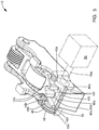
- FIG. 5 is the isometric view of FIG. 1 with an outer arm partially sectioned showing a lock pin in a decoupled position;
- FIG. 6 is the view of FIG. 5 now shown with the lock pin in a coupled position
- FIG. 7 is an enlarged isometric view of the lock pin.
- rocker arm 10 in accordance with the invention is illustrated where rocker arm 10 is either a two-step rocker arm or a deactivation rocker arm, which may generically be referred to as a switchable rocker arm.
- Rocker arm 10 is included in valve train (not shown) of an internal combustion engine (not shown) in order to translate rotational motion of a camshaft (not shown) to reciprocating motion of a combustion valve (not shown).
- Rocker arm 10 includes an inner arm 12 that is pivotably disposed in a central opening 16 of an outer arm 14 .
- Inner arm 12 is supported by, and selectively pivots within, outer arm 14 about a pivot shaft 18 which is supported at opposite ends thereof by outer arm 14 which is centered about, and extends along, a pivot axis 18 a .
- Inner arm 12 includes a follower illustrated as a roller 20 carried by a roller shaft 22 that is supported by inner arm 12 such that roller 20 and roller shaft 22 are centered about a roller shaft axis 24 .
- Roller 20 is configured to follow a lobe of the camshaft, for example a high-lift lobe, to impart lifting motion on a respective combustion valve.
- a bearing 26 may rotatably support roller 20 on roller shaft 22 for following a cam lobe of a lifting cam of an engine camshaft (not shown).
- Bearing 26 may be, for example, a plurality of rollers or needle bearings.
- Roller shaft 22 is fixed to inner arm 12 , by way of non-limiting example only by staking each end of roller shaft 22 in order to cause each end of roller shaft 22 to be increased in diameter to prevent removal from inner arm 12 .
- Outer arm 14 includes two walls 28 positioned parallel to each other such that walls 28 are perpendicular to roller shaft axis 24 and such that walls 28 are spaced apart from each other to define central opening 16 therebetween.
- Outer arm 14 also includes followers 30 such that one follower 30 is fixed to each wall 28 . As shown, followers 30 may be sliding surfaces, but may alternatively be rollers.
- a lost motion spring 32 acts between inner arm 12 and outer arm 14 to pivot inner arm 12 away from outer arm 14 in a first rotational direction (clockwise as viewed in FIGS. 3 and 4 ). More particularly, lost motion spring 32 may be a coiled torsion spring which circumferentially surrounds a central portion of pivot shaft 18 with a bushing 33 disposed radially between pivot shaft 18 and lost motion spring 32 such that a spring first end 32 a is grounded to inner arm 12 and such that a spring second end 32 b is grounded to outer arm 14 .
- a socket 34 for pivotably mounting rocker arm 10 on a lash adjuster is included in an outer arm body 35 at a first end 14 a of outer arm 14 where outer arm body 35 connects walls 28 at first end 14 a while a pad 36 for actuating a valve stem (not shown) is included at a second end 14 b of outer arm 14 such extends between each walls 28 , thereby connecting walls 28 at second end 14 b .
- a lock pin 40 disposed within outer arm 14 near first end 14 a thereof selectively permits inner arm 12 to pivot relative to outer arm 14 about pivot shaft 18 and also selectively prevents inner arm 12 from pivoting relative to outer arm 14 about pivot shaft 18 as will be described in greater detail later.
- lost motion spring 32 has been illustrated as a coiled torsion spring which circumferentially surrounds pivot shaft 18 , it should be understood that lost motion spring 32 may take numerous other forms, which may be, by way of non-limiting example only, a coiled torsion spring which does not circumferentially surround pivot shaft 18 or a compression spring which acts between opposing surfaces of inner arm 12 and outer arm 14 .
- Rocker arm 10 is selectively switched between a coupled state and a decoupled state by lock pin 40 .
- inner arm 12 In the coupled state as shown in FIG. 4 , inner arm 12 is prevented from pivoting relative to outer arm 14 past a predetermined position of inner arm 12 relative to outer arm 14 in a second rotational direction, shown as counterclockwise in FIG. 4 , which is opposite from the first rotational direction.
- inner arm 12 and therefore roller shaft 22 , is coupled to outer arm 14 , and rotation of the lifting cam is transferred from roller 20 through roller shaft 22 to pivotal movement of outer arm 14 about the lash adjuster which, in turn, reciprocates the associated valve.
- the decoupled state As shown in FIG.
- inner arm 12 is able to pivot relative to outer arm 14 past the predetermined position in the second rotational direction, i.e. counterclockwise as viewed in FIG. 3 .
- inner arm 12 and therefore roller shaft 22 , is decoupled from outer arm 14 .
- roller shaft 22 does not transfer rotation of the lifting cam to pivotal movement of outer arm 14 , and the associated valve is not reciprocated.
- inner arm 12 together with roller 20 and roller shaft 22 reciprocate within central opening 16 , thereby compressing and uncompressing lost motion spring 32 in a cyclic manner such that lost motion spring 32 biases inner arm 12 to pivot relative to outer arm 14 in the first rotational direction, shown as clockwise in FIG. 3 .
- Lock pin 40 will now be described in greater detail with continued reference to FIGS. 1-4 , and now with additional reference to FIGS. 5-7 .
- Lock pin 40 is received within a lock pin bore 42 defined by outer arm 14 such that lock pin bore 42 is centered about, and extends along, a lock pin bore axis 44 which is parallel to, and laterally offset from, pivot axis 18 a .
- Lock pin bore 42 generally includes three portions, namely, a lock pin bore first portion 42 a which extends through one wall 28 of outer arm 14 , a lock pin bore second portion 42 b which extends into the other wall 28 of outer arm 14 from central opening 16 , and a lock pin bore third portion 42 c which is axially between lock pin bore first portion 42 a and lock pin bore second portion 42 b and extends through outer arm body 35 .
- Lock pin bore first portion 42 a and lock pin bore second portion 42 b are each cylindrical surfaces which completely surround lock pin bore axis 44 .
- lock pin bore third portion 42 c is open to central opening 16 in a direction radially outward from lock pin bore axis 44 , and consequently, lock pin bore third portion 42 c is a sector of a cylindrical surface such that lock pin bore third portion 42 c has a radius that is equal to the radius of lock pin bore first portion 42 a and lock pin bore second portion 42 b .
- a lock pin bore counterbore 42 d extends from lock pin bore second portion 42 b to the outer surface of wall 28 that is opposed to central opening 16 .
- Lock pin 40 includes three portions, namely, a lock pin first portion 40 a at one axial end thereof, a lock pin second portion 40 b at the other axial end thereof, and a lock pin third portion 40 c which joins lock pin first portion 40 a and lock pin second portion 40 b .
- Lock pin first portion 40 a and lock pin second portion 40 b are each cylinders having a common diameter centered about lock pin bore axis 44 such that lock pin first portion 40 a is sized to interface with lock pin bore first portion 42 a in a close-sliding interface such that lock pin first portion 40 a is able to move freely within lock pin bore first portion 42 a along lock pin bore axis 44 while substantially preventing movement of lock pin first portion 40 a within lock pin bore first portion 42 a radially relative to lock pin bore axis 44 .
- lock pin second portion 40 b is sized to interface with lock pin bore second portion 42 b in a close-sliding interface such that lock pin second portion 40 b is able to move freely within lock pin bore second portion 42 b along lock pin bore axis 44 while substantially preventing movement of lock pin second portion 40 b within lock pin bore second portion 42 b radially relative to lock pin bore axis 44 .
- Lock pin third portion 40 c includes a lock pin surface 40 d which is a sector of a cylinder having a radius R 40 d which is centered about lock pin bore axis 44 and which is equal in magnitude to the radius R 40 a of lock pin first portion 40 a centered about lock pin bore axis 44 and also equal in magnitude to the radius R 40 b of lock pin second portion 40 b centered about lock pin bore axis 44 .
- Lock pin third portion 40 c also includes a lock pin stop surface 40 e which is planar and which extends axially from lock pin first portion 40 a to lock pin second portion 40 b such that the intersection of lock pin stop surface 40 e and lock pin first portion 40 a is a chord of a circle, thereby defining a circular segment on lock pin first portion 40 a and such that the intersection of lock pin stop surface 40 e and lock pin second portion 40 b is a chord of a circle, thereby defining a circular segment on lock pin second portion 40 b .
- Lock pin third portion 40 c also includes two lock pin slots 40 f which are parallel to each other and extend from lock pin surface 40 d inward for a distance that is greater than the radius of lock pin first portion 40 a and lock pin second portion 40 b such that lock pin slots 40 f face toward inner arm 12 . Furthermore, lock pin slots 40 f intersect with lock pin surface 40 d . While two lock pin slots 40 f have been illustrated herein, it should be understood that a lesser number or a greater number of lock pin slots 40 f may be provided.
- a return spring bore 40 g (shown only in FIG. 4 ) extends axially, i.e.
- return spring bore 40 g may be centered about lock pin bore axis 44 .
- a return spring 46 illustrated as a coil compression spring, is received within return spring bore 40 g as will be described in greater detail later.
- a retention plug 48 is disposed and fixed within lock pin bore counterbore 42 d in order to limit travel of lock pin 40 in a first axial direction, i.e. toward the upper left as viewed in FIGS. 5 and 6 .
- Retention plug 48 also serves as a surface upon which return spring 46 acts in order to bias lock pin 40 in a second axial direction i.e. toward the lower right as viewed in FIG. 5 .
- Retention plug 48 may be retained within lock pin bore counterbore 42 d with retainer ring 49 which is received within a complementary retention plug groove 48 a which extends radially inward from the outer periphery of retention plug 48 and within a complementary lock pin bore groove 42 e which extends radially outward from lock pin bore counterbore 42 d .
- retention plug 48 may be retained within lock pin bore counterbore 42 d using an interference fit, adhesive, welding, staking, and the like.
- a retention plug aperture 48 b may extend axially through retention plug 48 as shown in order to prevent an accumulation of oil (used to lubricate rocker arm 10 and other elements of the internal combustion engine) in the space between lock pin second portion 40 b and retention plug 48 because an accumulation of oil in this space may impact movement of lock pin 40 within lock pin bore 42 .
- retention plug 48 , retainer ring 49 , and related features of lock pin bore 42 may be omitted and lock pin bore second portion 42 b may be a blind bore where the bottom of the blind bore serves the same function as retention plug 48 .
- a retention pin 50 is provided in order to limit travel of lock pin 40 in the second axial direction, i.e. toward the lower right as viewed in FIG. 6 and to limit rotation of lock pin 40 about lock pin bore axis 44 within lock pin bore 42 .
- Retention pin 50 may also prevent lock pin 40 from being removed from lock pin bore 42 after manufacture of rocker arm 10 , but before rocker arm 10 is installed in the internal combustion engine.
- Retention pin 50 is received within a retention pin bore 52 which extends into outer arm 14 in a direction that is normal to lock pin bore axis 44 and which intersects lock pin bore 42 , and more specifically intersects with lock pin bore second portion 42 b . In this way, lock pin bore 42 interrupts retention pin bore 52 and separates retention pin bore 52 (shown only in FIG.
- an intermediate portion of retention pin 50 is located within lock pin bore 42 such that lock pin second portion 40 b is captured axially, i.e. in a direction parallel to lock pin bore axis 44 , between retention pin 50 and retention plug 48 . Furthermore, the intermediate portion of retention pin 50 is located between lock pin first portion 40 a and lock pin second portion 40 b . As may be best seen in FIGS.
- retention pin 50 may be a dowel pin as shown, or may alternatively be a roll pin. Retention pin 50 may be retained by interference fit with retention pin bore 52 or may alternatively, or in addition to, be retained by welding, staking, adhesive bonding, and the like. In an alternative arrangement that is not shown, retention pin bore second portion 52 b may be omitted and retention pin 50 is cantilevered such that retention pin 50 is supported only within retention pin bore first portion 52 a.
- Inner arm 12 includes inner arm protrusions 12 a which are sized and spaced to fit within lock pin slots 40 f when lock pin 40 is positioned within lock pin bore 42 in a decoupled position as shown in FIGS. 3 and 5 . Furthermore, inner arm protrusions 12 a define inner arm stop surfaces 12 b which are planar and which mate with lock pin stop surface 40 e when lock pin 40 is positioned within lock pin bore 42 in a coupled position as shown in FIGS. 4 and 6 . The decoupled position and coupled position of lock pin 40 will be described in greater detail later.
- inner arm 12 is illustrated herein as having two inner arm protrusions 12 a , it should be understood that two inner arm protrusions 12 a have been selected to be complementary to the quantity of lock pin slots 40 f . Consequently, the quantity of inner arm protrusions 12 a may be less in quantity or more in quantity depending on how many lock pin slots 40 f are provided in lock pin 40 .
- actuation means may be provided, illustrated schematically in phantom lines herein as solenoid 54 (shown only in FIGS. 5 and 6 ).
- Solenoid 54 includes an actuation rod 54 a which is axially displaceable by application of electricity to a coil (not shown) of solenoid 54 which creates a magnetic attraction between elements (not shown) within solenoid 54 which causes actuation rod 54 a to move in the first axial direction, i.e. toward the upper left as viewed and shown in FIG.
- FIG. 4 shows inner arm 12 in the predetermined position
- FIG. 3 shows inner arm 12 pivoted past the predetermined position in the second rotational direction.
- lock pin second portion 40 b when lock pin 40 is the decoupled position, lock pin second portion 40 b is located within retention plug 48 such that lock pin second portion 40 b is circumferentially surrounded by retention plug 48 and such that lock pin second portion 40 b is entirely removed from lock pin bore second portion 42 b .
- the magnetic attraction of the elements within solenoid 54 ceases, thereby eliminating the force of actuation rod 54 a on lock pin 40 in the first axial direction.
- return spring 46 urges lock pin 40 and actuation rod 54 a in the second axial direction, i.e. toward the lower left as viewed and shown in FIG.
- FIG. 4 shows inner arm 12 in the predetermined position.
- Solenoids such as solenoid 54 are well known to those of ordinary skill in the art, and consequently, solenoid 54 will not be described further herein.
- actuation means has been illustrated as solenoid 54 , it should be understood that the actuation means may take the form of any one of a number of alternatives, which may be, by way of non-limiting example only, hydraulic actuation which includes a hydraulic chamber in which pressurized fluid, such as engine oil, is selectively provided to urge lock pin 40 in the first axial direction.
- hydraulic actuation which includes a hydraulic chamber in which pressurized fluid, such as engine oil, is selectively provided to urge lock pin 40 in the first axial direction.
- a first imaginary line 56 extending perpendicular through lock pin bore axis 44 and perpendicular to inner arm stop surface 12 b extends through inner arm stop surface 12 b .
- inner arm stop surfaces 12 b extend over lock pin bore axis 44 , thereby preventing rotation of lock pin 40 by inner arm 12 since force from inner arm 12 is applied to lock pin stop surface 40 e on each side of lock pin bore axis 44 .
- a second imaginary line 58 is oblique relative to first imaginary line 56 when inner arm 12 is in the predetermined position such that second imaginary line 58 extends perpendicular through pivot axis 18 a and through an intersection of first imaginary line 56 and inner arm stop surface 12 b .
- the force from inner arm 12 is transferred into outer arm body 35 at lock pin bore third portion 42 c such that forces from inner arm 12 pass through imaginary line 56 which places lock pin 40 in compression against lock pin bore third portion 42 c where FIG. 4 shows that imaginary line 56 consequently passes through lock pin bore third portion 42 .
Abstract
Description
Claims (14)
Priority Applications (1)
| Application Number | Priority Date | Filing Date | Title |
|---|---|---|---|
| US15/955,215 US10605126B2 (en) | 2018-04-17 | 2018-04-17 | Switchable rocker arm |
Applications Claiming Priority (1)
| Application Number | Priority Date | Filing Date | Title |
|---|---|---|---|
| US15/955,215 US10605126B2 (en) | 2018-04-17 | 2018-04-17 | Switchable rocker arm |
Publications (2)
| Publication Number | Publication Date |
|---|---|
| US20190316494A1 US20190316494A1 (en) | 2019-10-17 |
| US10605126B2 true US10605126B2 (en) | 2020-03-31 |
Family
ID=68160259
Family Applications (1)
| Application Number | Title | Priority Date | Filing Date |
|---|---|---|---|
| US15/955,215 Active 2038-05-02 US10605126B2 (en) | 2018-04-17 | 2018-04-17 | Switchable rocker arm |
Country Status (1)
| Country | Link |
|---|---|
| US (1) | US10605126B2 (en) |
Families Citing this family (7)
| Publication number | Priority date | Publication date | Assignee | Title |
|---|---|---|---|---|
| US10815840B2 (en) * | 2018-06-05 | 2020-10-27 | Schaeffler Technologies AG & Co. KG | Coupling assembly for switchable lever |
| US11300014B2 (en) | 2018-12-06 | 2022-04-12 | Jacobs Vehicle Systems, Inc. | Valve actuation system comprising finger follower for lobe switching and single source lost motion |
| US11208921B2 (en) | 2018-12-06 | 2021-12-28 | Jacobs Vehicle Systems, Inc. | Finger follower for lobe switching and single source lost motion |
| BR112021010547A2 (en) | 2018-12-06 | 2021-08-24 | Jacobs Vehicle Systems, Inc. | Follower rocker for single source lobe switching and lost motion |
| WO2020151924A1 (en) * | 2019-01-24 | 2020-07-30 | Eaton Intelligent Power Limited | Rocker arm assembly having lash management for cylinder deactivation and engine brake configuration |
| CN114846223B (en) * | 2020-01-16 | 2023-10-27 | 伊顿智能动力有限公司 | Latch assembly and compact rocker arm assembly |
| WO2023001408A1 (en) * | 2021-07-23 | 2023-01-26 | Eaton Intelligent Power Limited | Swithing roller finger follower with transverse latch pin |
Citations (20)
| Publication number | Priority date | Publication date | Assignee | Title |
|---|---|---|---|---|
| US4768467A (en) | 1986-01-23 | 1988-09-06 | Fuji Jukogyo Kabushiki Kaisha | Valve operating system for an automotive engine |
| US5544626A (en) | 1995-03-09 | 1996-08-13 | Ford Motor Company | Finger follower rocker arm with engine valve deactivator |
| US5653198A (en) | 1996-01-16 | 1997-08-05 | Ford Motor Company | Finger follower rocker arm system |
| US20010023675A1 (en) | 2000-01-14 | 2001-09-27 | Jongmin Lee | Method and apparatus for two-step cam profile switching |
| US6314928B1 (en) | 2000-12-06 | 2001-11-13 | Ford Global Technologies, Inc. | Rocker arm assembly |
| US6321705B1 (en) | 1999-10-15 | 2001-11-27 | Delphi Technologies, Inc. | Roller finger follower for valve deactivation |
| US6532920B1 (en) | 2002-02-08 | 2003-03-18 | Ford Global Technologies, Inc. | Multipositional lift rocker arm assembly |
| DE10155827A1 (en) | 2001-11-14 | 2003-05-15 | Ina Schaeffler Kg | Rocker arm used in a valve gear of an internal combustion engine has an outer lever having arms, and an inner lever having a running surface for a cam |
| WO2003042510A1 (en) | 2001-11-14 | 2003-05-22 | Ina-Schaeffler Kg | Drag lever of a valve mechanism in an internal combustion engine |
| DE4444499C2 (en) | 1994-04-14 | 2003-06-18 | Ina Schaeffler Kg | Device for the simultaneous actuation of at least two gas exchange valves |
| US6655331B2 (en) * | 2000-08-09 | 2003-12-02 | Fev Motorentechnik Gmbh | Piston-type internal-combustion engine having activatable, mechanically actuated cylinder valves |
| US20050247279A1 (en) | 2002-12-11 | 2005-11-10 | Bodo Rorig | Finger lever of a valve train of an internal combustion engine |
| US7305951B2 (en) | 2005-05-09 | 2007-12-11 | Delphi Technologies, Inc. | Two-step roller finger follower |
| US20080202457A1 (en) * | 2007-02-27 | 2008-08-28 | Taku Hirayama | Engine |
| US7614375B2 (en) | 2006-09-26 | 2009-11-10 | Delphi Technologies, Inc. | Roller bearing and z-stop for a two-step roller finger follower |
| US7798113B2 (en) | 2007-06-20 | 2010-09-21 | Delphi Technologies, Inc. | Two-step roller finger cam follower assembly having a follower travel limiter |
| US20100300389A1 (en) * | 2009-06-01 | 2010-12-02 | Schaeffler Technologies Gmbh & Co. Kg | Switchable finger lever |
| US7882814B2 (en) | 2008-03-03 | 2011-02-08 | Delphi Technologies, Inc. | Inner arm stop for a switchable rocker arm |
| DE102015002982A1 (en) * | 2015-03-09 | 2016-09-15 | Meta Motoren- Und Energie-Technik Gmbh | Device for switching over the operation of a charge exchange valve of an internal combustion engine |
| US20170009610A1 (en) * | 2015-07-09 | 2017-01-12 | Schaeffler Technologies AG & Co. KG | Switchable rocker arm with pivot joint |
-
2018
- 2018-04-17 US US15/955,215 patent/US10605126B2/en active Active
Patent Citations (20)
| Publication number | Priority date | Publication date | Assignee | Title |
|---|---|---|---|---|
| US4768467A (en) | 1986-01-23 | 1988-09-06 | Fuji Jukogyo Kabushiki Kaisha | Valve operating system for an automotive engine |
| DE4444499C2 (en) | 1994-04-14 | 2003-06-18 | Ina Schaeffler Kg | Device for the simultaneous actuation of at least two gas exchange valves |
| US5544626A (en) | 1995-03-09 | 1996-08-13 | Ford Motor Company | Finger follower rocker arm with engine valve deactivator |
| US5653198A (en) | 1996-01-16 | 1997-08-05 | Ford Motor Company | Finger follower rocker arm system |
| US6321705B1 (en) | 1999-10-15 | 2001-11-27 | Delphi Technologies, Inc. | Roller finger follower for valve deactivation |
| US20010023675A1 (en) | 2000-01-14 | 2001-09-27 | Jongmin Lee | Method and apparatus for two-step cam profile switching |
| US6655331B2 (en) * | 2000-08-09 | 2003-12-02 | Fev Motorentechnik Gmbh | Piston-type internal-combustion engine having activatable, mechanically actuated cylinder valves |
| US6314928B1 (en) | 2000-12-06 | 2001-11-13 | Ford Global Technologies, Inc. | Rocker arm assembly |
| WO2003042510A1 (en) | 2001-11-14 | 2003-05-22 | Ina-Schaeffler Kg | Drag lever of a valve mechanism in an internal combustion engine |
| DE10155827A1 (en) | 2001-11-14 | 2003-05-15 | Ina Schaeffler Kg | Rocker arm used in a valve gear of an internal combustion engine has an outer lever having arms, and an inner lever having a running surface for a cam |
| US6532920B1 (en) | 2002-02-08 | 2003-03-18 | Ford Global Technologies, Inc. | Multipositional lift rocker arm assembly |
| US20050247279A1 (en) | 2002-12-11 | 2005-11-10 | Bodo Rorig | Finger lever of a valve train of an internal combustion engine |
| US7305951B2 (en) | 2005-05-09 | 2007-12-11 | Delphi Technologies, Inc. | Two-step roller finger follower |
| US7614375B2 (en) | 2006-09-26 | 2009-11-10 | Delphi Technologies, Inc. | Roller bearing and z-stop for a two-step roller finger follower |
| US20080202457A1 (en) * | 2007-02-27 | 2008-08-28 | Taku Hirayama | Engine |
| US7798113B2 (en) | 2007-06-20 | 2010-09-21 | Delphi Technologies, Inc. | Two-step roller finger cam follower assembly having a follower travel limiter |
| US7882814B2 (en) | 2008-03-03 | 2011-02-08 | Delphi Technologies, Inc. | Inner arm stop for a switchable rocker arm |
| US20100300389A1 (en) * | 2009-06-01 | 2010-12-02 | Schaeffler Technologies Gmbh & Co. Kg | Switchable finger lever |
| DE102015002982A1 (en) * | 2015-03-09 | 2016-09-15 | Meta Motoren- Und Energie-Technik Gmbh | Device for switching over the operation of a charge exchange valve of an internal combustion engine |
| US20170009610A1 (en) * | 2015-07-09 | 2017-01-12 | Schaeffler Technologies AG & Co. KG | Switchable rocker arm with pivot joint |
Also Published As
| Publication number | Publication date |
|---|---|
| US20190316494A1 (en) | 2019-10-17 |
Similar Documents
| Publication | Publication Date | Title |
|---|---|---|
| US10605126B2 (en) | Switchable rocker arm | |
| US7546822B2 (en) | Switching finger follower assembly | |
| US6691657B2 (en) | Two-step finger follower rocker arm | |
| US6668779B2 (en) | Two-step finger follower rocker arm assembly | |
| US10253657B2 (en) | Switchable rocker arm with a travel stop | |
| US20080283003A1 (en) | Two-step roller finger cam follower | |
| US4227494A (en) | Valve disabler and control | |
| US10533463B1 (en) | Switchable rocker arm and roller retainer thereof | |
| US10605125B2 (en) | Switching rocker arm | |
| US10472998B2 (en) | Switchable rocker arm with lash adjustment | |
| CN115667676A (en) | Rocker arm | |
| US10054014B1 (en) | Latching arrangement for switchable rocker arm | |
| US10465566B2 (en) | Switchable rocker arm with a travel stop | |
| US11828205B2 (en) | Latch assembly and compact rocker arm assembly | |
| US10519817B1 (en) | Switchable rocker arm with lash adjustment and travel stop | |
| US10900385B2 (en) | Switchable rocker arm | |
| US10704429B2 (en) | Switchable rocker arm | |
| US10677106B2 (en) | Rocker arm | |
| US10544711B1 (en) | Switchable rocker arm and roller retainer thereof | |
| US10871087B2 (en) | Switchable rocker arm |
Legal Events
| Date | Code | Title | Description |
|---|---|---|---|
| AS | Assignment |
Owner name: DELPHI TECHNOLOGIES IP LIMITED, BARBADOS Free format text: ASSIGNMENT OF ASSIGNORS INTEREST;ASSIGNORS:MARIUZ, ROBERT M.;KEEGAN, KEVIN R.;FERNANDEZ, HERMES A.;SIGNING DATES FROM 20180416 TO 20180417;REEL/FRAME:045563/0845 |
|
| FEPP | Fee payment procedure |
Free format text: ENTITY STATUS SET TO UNDISCOUNTED (ORIGINAL EVENT CODE: BIG.); ENTITY STATUS OF PATENT OWNER: LARGE ENTITY |
|
| STPP | Information on status: patent application and granting procedure in general |
Free format text: RESPONSE TO NON-FINAL OFFICE ACTION ENTERED AND FORWARDED TO EXAMINER |
|
| STPP | Information on status: patent application and granting procedure in general |
Free format text: NOTICE OF ALLOWANCE MAILED -- APPLICATION RECEIVED IN OFFICE OF PUBLICATIONS |
|
| STPP | Information on status: patent application and granting procedure in general |
Free format text: PUBLICATIONS -- ISSUE FEE PAYMENT RECEIVED |
|
| STPP | Information on status: patent application and granting procedure in general |
Free format text: PUBLICATIONS -- ISSUE FEE PAYMENT VERIFIED |
|
| STCF | Information on status: patent grant |
Free format text: PATENTED CASE |
|
| AS | Assignment |
Owner name: UNITED STATES DEPARTMENT OF ENERGY, DISTRICT OF COLUMBIA Free format text: CONFIRMATORY LICENSE;ASSIGNOR:DELPHI POWERTRAIN SYSTEMS, LLC;REEL/FRAME:063779/0604 Effective date: 20230328 |
|
| MAFP | Maintenance fee payment |
Free format text: PAYMENT OF MAINTENANCE FEE, 4TH YEAR, LARGE ENTITY (ORIGINAL EVENT CODE: M1551); ENTITY STATUS OF PATENT OWNER: LARGE ENTITY Year of fee payment: 4 |