EP4089998A1 - Camera module, electronic device, and camera module control method - Google Patents
Camera module, electronic device, and camera module control method Download PDFInfo
- Publication number
- EP4089998A1 EP4089998A1 EP21743729.2A EP21743729A EP4089998A1 EP 4089998 A1 EP4089998 A1 EP 4089998A1 EP 21743729 A EP21743729 A EP 21743729A EP 4089998 A1 EP4089998 A1 EP 4089998A1
- Authority
- EP
- European Patent Office
- Prior art keywords
- camera
- lens
- optical axis
- axis direction
- camera module
- Prior art date
- Legal status (The legal status is an assumption and is not a legal conclusion. Google has not performed a legal analysis and makes no representation as to the accuracy of the status listed.)
- Pending
Links
Images

Classifications
-
- H—ELECTRICITY
- H04—ELECTRIC COMMUNICATION TECHNIQUE
- H04N—PICTORIAL COMMUNICATION, e.g. TELEVISION
- H04N23/00—Cameras or camera modules comprising electronic image sensors; Control thereof
- H04N23/60—Control of cameras or camera modules
- H04N23/69—Control of means for changing angle of the field of view, e.g. optical zoom objectives or electronic zooming
-
- H—ELECTRICITY
- H04—ELECTRIC COMMUNICATION TECHNIQUE
- H04N—PICTORIAL COMMUNICATION, e.g. TELEVISION
- H04N23/00—Cameras or camera modules comprising electronic image sensors; Control thereof
- H04N23/50—Constructional details
-
- H—ELECTRICITY
- H04—ELECTRIC COMMUNICATION TECHNIQUE
- H04N—PICTORIAL COMMUNICATION, e.g. TELEVISION
- H04N23/00—Cameras or camera modules comprising electronic image sensors; Control thereof
- H04N23/50—Constructional details
- H04N23/51—Housings
-
- G—PHYSICS
- G02—OPTICS
- G02B—OPTICAL ELEMENTS, SYSTEMS OR APPARATUS
- G02B15/00—Optical objectives with means for varying the magnification
- G02B15/02—Optical objectives with means for varying the magnification by changing, adding, or subtracting a part of the objective, e.g. convertible objective
-
- G—PHYSICS
- G02—OPTICS
- G02B—OPTICAL ELEMENTS, SYSTEMS OR APPARATUS
- G02B7/00—Mountings, adjusting means, or light-tight connections, for optical elements
- G02B7/02—Mountings, adjusting means, or light-tight connections, for optical elements for lenses
- G02B7/021—Mountings, adjusting means, or light-tight connections, for optical elements for lenses for more than one lens
-
- G—PHYSICS
- G02—OPTICS
- G02B—OPTICAL ELEMENTS, SYSTEMS OR APPARATUS
- G02B7/00—Mountings, adjusting means, or light-tight connections, for optical elements
- G02B7/02—Mountings, adjusting means, or light-tight connections, for optical elements for lenses
- G02B7/04—Mountings, adjusting means, or light-tight connections, for optical elements for lenses with mechanism for focusing or varying magnification
- G02B7/08—Mountings, adjusting means, or light-tight connections, for optical elements for lenses with mechanism for focusing or varying magnification adapted to co-operate with a remote control mechanism
-
- G—PHYSICS
- G03—PHOTOGRAPHY; CINEMATOGRAPHY; ANALOGOUS TECHNIQUES USING WAVES OTHER THAN OPTICAL WAVES; ELECTROGRAPHY; HOLOGRAPHY
- G03B—APPARATUS OR ARRANGEMENTS FOR TAKING PHOTOGRAPHS OR FOR PROJECTING OR VIEWING THEM; APPARATUS OR ARRANGEMENTS EMPLOYING ANALOGOUS TECHNIQUES USING WAVES OTHER THAN OPTICAL WAVES; ACCESSORIES THEREFOR
- G03B17/00—Details of cameras or camera bodies; Accessories therefor
- G03B17/02—Bodies
- G03B17/04—Bodies collapsible, foldable or extensible, e.g. book type
-
- G—PHYSICS
- G03—PHOTOGRAPHY; CINEMATOGRAPHY; ANALOGOUS TECHNIQUES USING WAVES OTHER THAN OPTICAL WAVES; ELECTROGRAPHY; HOLOGRAPHY
- G03B—APPARATUS OR ARRANGEMENTS FOR TAKING PHOTOGRAPHS OR FOR PROJECTING OR VIEWING THEM; APPARATUS OR ARRANGEMENTS EMPLOYING ANALOGOUS TECHNIQUES USING WAVES OTHER THAN OPTICAL WAVES; ACCESSORIES THEREFOR
- G03B30/00—Camera modules comprising integrated lens units and imaging units, specially adapted for being embedded in other devices, e.g. mobile phones or vehicles
-
- G—PHYSICS
- G03—PHOTOGRAPHY; CINEMATOGRAPHY; ANALOGOUS TECHNIQUES USING WAVES OTHER THAN OPTICAL WAVES; ELECTROGRAPHY; HOLOGRAPHY
- G03B—APPARATUS OR ARRANGEMENTS FOR TAKING PHOTOGRAPHS OR FOR PROJECTING OR VIEWING THEM; APPARATUS OR ARRANGEMENTS EMPLOYING ANALOGOUS TECHNIQUES USING WAVES OTHER THAN OPTICAL WAVES; ACCESSORIES THEREFOR
- G03B5/00—Adjustment of optical system relative to image or object surface other than for focusing
-
- H—ELECTRICITY
- H04—ELECTRIC COMMUNICATION TECHNIQUE
- H04N—PICTORIAL COMMUNICATION, e.g. TELEVISION
- H04N23/00—Cameras or camera modules comprising electronic image sensors; Control thereof
- H04N23/50—Constructional details
- H04N23/54—Mounting of pick-up tubes, electronic image sensors, deviation or focusing coils
-
- H—ELECTRICITY
- H04—ELECTRIC COMMUNICATION TECHNIQUE
- H04N—PICTORIAL COMMUNICATION, e.g. TELEVISION
- H04N23/00—Cameras or camera modules comprising electronic image sensors; Control thereof
- H04N23/50—Constructional details
- H04N23/55—Optical parts specially adapted for electronic image sensors; Mounting thereof
-
- H—ELECTRICITY
- H04—ELECTRIC COMMUNICATION TECHNIQUE
- H04N—PICTORIAL COMMUNICATION, e.g. TELEVISION
- H04N23/00—Cameras or camera modules comprising electronic image sensors; Control thereof
- H04N23/57—Mechanical or electrical details of cameras or camera modules specially adapted for being embedded in other devices
-
- H—ELECTRICITY
- H04—ELECTRIC COMMUNICATION TECHNIQUE
- H04N—PICTORIAL COMMUNICATION, e.g. TELEVISION
- H04N23/00—Cameras or camera modules comprising electronic image sensors; Control thereof
- H04N23/60—Control of cameras or camera modules
- H04N23/61—Control of cameras or camera modules based on recognised objects
-
- H—ELECTRICITY
- H04—ELECTRIC COMMUNICATION TECHNIQUE
- H04N—PICTORIAL COMMUNICATION, e.g. TELEVISION
- H04N23/00—Cameras or camera modules comprising electronic image sensors; Control thereof
- H04N23/60—Control of cameras or camera modules
- H04N23/62—Control of parameters via user interfaces
-
- G—PHYSICS
- G03—PHOTOGRAPHY; CINEMATOGRAPHY; ANALOGOUS TECHNIQUES USING WAVES OTHER THAN OPTICAL WAVES; ELECTROGRAPHY; HOLOGRAPHY
- G03B—APPARATUS OR ARRANGEMENTS FOR TAKING PHOTOGRAPHS OR FOR PROJECTING OR VIEWING THEM; APPARATUS OR ARRANGEMENTS EMPLOYING ANALOGOUS TECHNIQUES USING WAVES OTHER THAN OPTICAL WAVES; ACCESSORIES THEREFOR
- G03B2205/00—Adjustment of optical system relative to image or object surface other than for focusing
- G03B2205/0046—Movement of one or more optical elements for zooming
-
- H—ELECTRICITY
- H04—ELECTRIC COMMUNICATION TECHNIQUE
- H04N—PICTORIAL COMMUNICATION, e.g. TELEVISION
- H04N23/00—Cameras or camera modules comprising electronic image sensors; Control thereof
- H04N23/60—Control of cameras or camera modules
- H04N23/667—Camera operation mode switching, e.g. between still and video, sport and normal or high- and low-resolution modes
Definitions
- the present invention relates to the field of communications device technologies, and in particular, to a camera module, an electronic device, and a camera module control method.
- a camera module is used as an example, and a photographing capability of the electronic device becomes an important standard for measuring performance of the electronic device.
- a quantity of cameras of the camera module is developed from a single camera to multiple cameras, so that the camera module can implement a zooming effect, and therefore, a photographing effect of the camera module is better.
- the present invention discloses a camera module, an electronic device, and a camera module control method, which can resolve a problem that a camera module of a current electronic device cannot implement a high-multiple zooming function.
- an embodiment of the present invention provides a camera module, including:
- an embodiment of the present invention provides an electronic device, including a device body and the foregoing camera module, where the camera module capable of being connected to the device body.
- an embodiment of the present invention provides a camera module control method, applied to the foregoing camera module, where the control method includes:
- an embodiment of the present invention provides an electronic device, including a processor, a memory, and a computer program that is stored in the memory and that can run on the processor, and when the computer program is executed by the processor, steps of the foregoing control method are implemented.
- an embodiment of this application provides a readable storage medium, where the readable storage medium stores a program or an instruction, and the program or the instruction is executed by a processor to implement the steps of the control method according to the third aspect.
- the projection of the camera in the optical axis direction at least partially overlaps the projection of the lens in the optical axis direction.
- light passes through the lens first, and then enters the camera, so that a high-multiple zooming function can be implemented. In this way, a photographing effect of the camera module is better, and a photographing requirement of a user can be finally satisfied.
- an embodiment of the present invention discloses a camera module, and the disclosed camera module includes a first bracket 100, a lens 200, and a camera assembly 300.
- the first bracket 100 can provide a mounting position for another component of the camera module.
- the first bracket 100 may be a frame-shaped structure or a plate-shaped structure.
- a specific structure of the first bracket 100 is not limited in this embodiment of the present invention.
- the lens 200 is one of important components of the camera module.
- the lens 200 is disposed on the first bracket 100.
- a mounting hole may be disposed on the first bracket 100.
- the lens 200 may be installed in the mounting hole through bonding, threaded connection, clamping, magnetic suction connection, or the like.
- the lens 200 may be disposed in a removable structure, or may be disposed in a non-removable structure.
- a specific manner of mounting the lens 200 on the first bracket 100 is not limited in this embodiment of the present invention.
- the camera assembly 300 includes a camera 310 and a second bracket 320, and the camera 310 is disposed on the second bracket 320.
- the second bracket 320 may be a frame-shaped structural member.
- the camera 310 may be disposed in an inner cavity of the second bracket 320.
- an apparatus such as a circuit board for controlling the camera 310 to shoot may also be disposed in the inner cavity of the second bracket 320, so that a structure of the camera module is relatively compact.
- a lens 330 opposite to the camera 310 may also be disposed on a surface of the second bracket 320, so that the camera assembly 300 can perform normal photographing, and the camera 310 can be protected.
- the second bracket 320 and the first bracket 100 are slidably sleeved.
- the second bracket 320 and the first bracket 100 move relative to each other, so that the camera 310 and the lens 200 can be in relative positions.
- the camera 310 can face a working surface of the lens 200, and the camera 310 captures an image at a far distance by using the lens 200.
- an optical axis direction of the lens 200 is parallel to an optical axis direction of the camera 310.
- At least one of the camera 310 and the lens 200 may move between a first position and a second position.
- a solution in which the camera 310 or the lens 200 is movable may be used, or a solution in which both the camera 310 and the lens 200 are movable may be used.
- a projection of the camera 310 in the optical axis direction is staggered from a projection of the lens 200 in the optical axis direction.
- the projection of the camera 310 in the optical axis direction at least partially overlaps the projection of the lens 200 in the optical axis direction.
- a user may control the camera 310 or the lens 200 to move in a direction in which a relative distance between the lens 200 and the camera 310 increases, so that the projection of the camera 310 in the optical axis direction is staggered from the projection of the lens 200 in the optical axis direction.
- the user may control the camera 310 or the lens 200 to move in a direction in which the relative distance between the lens 200 and the camera 310 decreases, so that the projection of the camera 310 in the optical axis direction at least partially overlaps the projection of the lens 200 in the optical axis direction, and finally, the camera module can shoot a clearer image of the photographing subject.
- the projection of the camera 310 in the optical axis direction at least partially overlaps the projection of the lens 200 in the optical axis direction.
- light passes through the lens 200 first, and then enters the camera 310, so that a high-multiple zooming function can be implemented. In this way, a photographing effect of the camera module is better, and a photographing requirement of the user can be finally satisfied.
- the at least two lenses 200 may be disposed in a one-to-one correspondence on the at least two first brackets 100, and the at least two first brackets 100 may be slidably sleeved in sequence.
- the second bracket 320 may be slidably sleeved with the at least two first brackets 100.
- the second bracket 320 and the at least two first brackets 100 move relative to each other, so that the projection of the camera 310 in the optical axis direction may at least partially overlap projections of the at least two lenses 200 in the optical axis direction.
- the camera module can implement a higher-multiple zooming function, and the camera module can shoot an image at a far distance.
- the camera module may adjust, based on a specific position of the photographing subject, a quantity of lenses 200 that face the camera 310, so that the camera module can obtain a proper target focal length, and finally obtain a relatively clear image.
- one of the camera assembly 300 and the first bracket 100 may be disposed with a first limiting portion, and another may be disposed with a second limiting portion.
- the second bracket 320 of the camera assembly 300 may be disposed with the first limiting portion or the second limiting portion described herein.
- the first limiting portion may cooperate with the second limiting portion through limiting, so that the projection of the camera 310 in the optical axis direction may stably at least partially overlap the projection of the lens 200 in the optical axis direction, thereby preventing the projection of the camera 310 in the optical axis direction from being staggered from the projection of the lens 200 in the optical axis direction and affecting a photographing effect of the camera module.
- a third limiting portion may be disposed on one of two adjacent first brackets 100, and a fourth limiting portion may be disposed on the other.
- the third limiting portion and the fourth limiting portion may cooperate with each other through limiting, so that the two first brackets 100 can be maintained in the foregoing position, thereby preventing the projection of the lens 200 on one of the first brackets 100 in the optical axis direction and the projection of the lens 200 on other first bracket 100 in the optical axis direction from being staggered and affecting a photographing effect of the camera module.
- the first limiting portion and the second limiting portion may be in multiple specific structures.
- one of the first limiting portion and the second limiting portion may be a slot
- another of the first limiting portion and the second limiting portion may be a protrusion
- the slot and the protrusion may be limited
- at least one of the first limiting portion and the second limiting portion may be a magnetic suction part.
- the first limiting portion and the second limiting portion may be connected through magnetic suction.
- the first limiting portion and the second limiting portion may further have multiple specific structures. Specific structures of the first limiting portion and the second limiting portion are not limited in the present invention.
- a corresponding limiting mechanism may also be disposed between the camera assembly 300 and the first bracket 100, to prevent the camera assembly 300 from being separated from the first bracket 100.
- a first-gear protrusion may be disposed on one of the camera assembly 300 and the first bracket 100, and a second-gear protrusion may be disposed on the other.
- the first-gear protrusion cooperates with the second-gear protrusion through limiting, to prevent the camera assembly 300 from being separated from the first bracket 100.
- the camera module may further include a first driving mechanism 400.
- the first driving mechanism 400 may be connected to the first bracket 100 or the second bracket 320.
- the first driving mechanism 400 may be connected to the first bracket 100, so that the first driving mechanism 400 may drive the first bracket 100 to move, to enable the lens 200 to move between the first position and the second position.
- the first driving mechanism 400 may also be connected to the second bracket 320, so that the first driving mechanism 400 may drive the second bracket 320 to move, to enable the camera 310 to move between the first position and the second position.
- the first driving mechanism 400 may drive the camera 310 or the lens 200 to move between the first position and the second position, so that the camera module can easily implement a zooming function, thereby improving photographing experience of the user.
- one of the first bracket 100 and the second bracket 320 may be disposed with a sliding groove, another may be disposed with a sliding protrusion, and the sliding groove and the sliding protrusion may slidably cooperate with each other.
- the sliding groove and the sliding protrusion can play a better guiding role, so that sliding between the first bracket 100 and the second bracket 320 is more stable, thereby preventing a jam phenomenon.
- the sliding groove and the sliding protrusion can further play a better limiting role, o prevent the first bracket 100 and the second bracket 320 from being staggered and affecting a photographing effect of the camera module.
- an electronic device is further disclosed in an embodiment of the present invention.
- the disclosed electronic device includes a device body and the camera module described in any one of the foregoing embodiments, and the camera module capable of being connected to the device body.
- the device body may include a housing, the housing is a peripheral component of the device body, and the housing can provide a mounting position for another component of the electronic device.
- the electronic device may further include a second driving mechanism.
- the second driving mechanism is disposed inside the housing of the device body, and the second driving mechanism may be connected to the first bracket 100 or the second bracket 320.
- the second driving mechanism may drive the camera 310 or the lens 200 to move between the first position and the second position, so that the camera module can easily implement a zooming function.
- at least portion of the camera module may be exposed outside the housing, so that the camera module may work outside the housing.
- the camera module may alternatively be disposed inside the housing. In this case, a transparent area may be disposed inside the housing, and the camera module may face the transparent area, so that the camera module may work inside the housing.
- the foregoing first driving mechanism 400 may also drive the camera 310 or the lens 200 to move between the first position and the second position.
- only the first driving mechanism 400 or the second driving mechanism may be disposed to implement movement of the camera 310 or the lens 200, or both the first driving mechanism 400 and the second driving mechanism may be disposed. This is not limited in this embodiment of the present invention.
- the electronic device may further include a third driving mechanism
- the housing of the device body may be provided with an opening
- the third driving mechanism may be disposed inside the housing
- the third driving mechanism may be connected to the camera module.
- the third driving mechanism may drive at least portion camera module to extend out of the housing or retract to the housing by using the opening.
- the third driving mechanism may be controlled to drive at least portion the camera module to extend out of the housing through the opening, so that the camera module can work outside the housing, thereby improving the photographing effect of the camera module.
- the camera module may be located inside the housing.
- the camera module herein may implement front-facing photographing, or may implement rear-facing photographing.
- the camera module implements front-facing photographing
- the camera module does not occupy screen space of the electronic device, thereby increasing a screen-to-body ratio of the electronic device.
- a structure such as a transparent area does not need to be disposed on the housing corresponding to the camera module, to improve appearance quality of the electronic device, and in addition, a waterproof and dust-proof function can be implemented.
- the first driving mechanism 400, the second driving mechanism, and the third driving mechanism may be at least one of a hydraulic telescopic mechanism, a barometric telescopic mechanism, or a screw driving mechanism.
- Specific structures of the first driving mechanism 400, the second driving mechanism, and the second driving mechanism are not limited in the present invention.
- the screw driving mechanism may include a structure such as a motor, a screw, and a screw sleeve.
- the motor may drive the screw to rotate, and the screw sleeve is screwed with the screw, so that the screw may drive the screw sleeve to move, and the screw sleeve is connected to the first bracket 100, the second bracket 320, or the entire camera module, thereby driving the first bracket 100, the second bracket 320, or the entire camera module to move.
- the electronic device may have a first state and a second state.
- the camera module may be separated from the device body.
- the camera module and the device body may independently work without mutual interference, or the device body may control the camera module to work by using a wireless module, so that the camera module can play a photographing function more freely.
- the camera module capable of being connected to the device body.
- the device body and the camera module form a whole.
- the camera module may implement functions such as data transmission and charging by using the device body, or the device body may directly control the camera module to work.
- an embodiment of the present invention further discloses a camera module control method, and the disclosed control method includes following steps.
- the target focal length herein may be obtained based on a distance between the camera body and the camera 310.
- S200 Control the camera 310 or the lens 200 to move between a first position and a second position based on the target focal length, so that an actual focal length of the camera module is equal to the target focal length.
- the camera 310 or the lens 200 may be controlled to move between the first position and the second position, and the camera 310 cooperates with the lens 200, so that the actual focal length of the camera module is equal to the target focal length, to enable the camera module to obtain a relatively clear image.
- a projection of the camera 310 in an optical axis direction at least partially overlaps a projection of the lens 200 in the optical axis direction.
- light passes through the lens 200 first, and then enters the camera 310, so that a high-multiple zooming function can be implemented. In this way, a photographing effect of the camera module is better, and a photographing requirement of a user can be finally satisfied.
- step S100 specifically includes following steps.
- S110 Receive a first input performed by a user, where the first input is used to trigger a photographing operation.
- S 120 In response to the first input, perform scene recognition on an environment in which a photographing subject is located, to obtain the target focal length that matches a recognized scene.
- the user may first trigger a photographing operation by clicking a photographing button or the like.
- the camera module may receive a first input performed by the user, and after obtaining the first input performed by the user, the camera module may perform scene recognition on the environment in which the photographing subject is located.
- a human-machine interaction interface may be disposed on the camera module, and the user may enter a corresponding parameter on the human-machine interaction interface, so that the electronic device may perform, based on this parameter, scene recognition on the environment in which the photographing subject is located.
- a sensing module may be disposed on the camera module, and the camera module may perform scene identification on the photographing subject by using the sensing module.
- a correspondence table between the recognized scenario and the target focal length may be pre-stored on the electronic device. After a scene recognition operation is implemented, the target focal length that matches the recognized scenario may be obtained according to the correspondence table.
- step S200 may specifically include following steps.
- step S210 may be implemented.
- the foregoing actual focal length may be different from the target focal length, and therefore, step S210 may also be implemented.
- S220 In a case that the actual focal length is not equal to the target focal length, detect whether a projection of each lens 200 in an optical axis direction is staggered from a projection of the camera 310 in the optical axis direction.
- S240 In a case that a projection of at least one lens 200 in the optical axis direction at least partially overlaps the projection of the camera 310 in the optical axis direction, detect whether the projection of each lens 200 in the optical axis direction at least partially overlaps the projection of the camera 310 in the optical axis direction.
- the first direction is a direction in which a relative distance between the lens 200 and the camera 310 decreases, that is, a direction in which the lens 200 and the camera 310 approach each other
- the second direction is opposite to the first direction, that is, a direction in which the relative distance between the lens 200 and the camera 310 increases.
- an embodiment of the present invention further provides an electronic device.
- the electronic device may include:
- the obtaining module may include a receiving unit and a scene recognition unit.
- the receiving unit is configured to receive a first input performed by a user
- the scene recognition unit is configured to perform, in response to the first input, scene recognition on an environment in which a photographing subject is located, to obtain the target focal length that matches a recognized scene.
- control module may include:
- the first direction is a direction in which a relative distance between the lens 200 and the camera 310 decreases
- the second direction is opposite to the first direction, that is, a direction in which the relative distance between the lens 200 and the camera 310 increases.
- An embodiment of the present invention further discloses an electronic device, including a processor, a memory, and a computer program that is stored in the memory and that can run on the processor.
- the computer program is executed by the processor, steps of the control method in any one of the foregoing embodiments are implemented.
- An embodiment of the present invention further discloses a computer-readable storage medium, where the computer-readable storage medium stores a computer program, and when the computer program is executed by a processor, steps of the control method in any one of the foregoing embodiments are implemented.
- the processor is a processor in the electronic device in the foregoing embodiment.
- the readable storage medium includes a computer-readable storage medium such as a read-only memory (Read-Only Memory, ROM), a random access memory (Random Access Memory, RAM), a magnetic disk, an optical disc, or the like.
- the electronic device disclosed in the embodiments of the present invention may be a device such as a smartphone, a tablet computer, an e-book reader, a wearable device (for example, a smart watch), or a video game.
- a specific type of the electronic device is not limited in the embodiments of the present invention.
Landscapes
- Engineering & Computer Science (AREA)
- Multimedia (AREA)
- Signal Processing (AREA)
- Physics & Mathematics (AREA)
- General Physics & Mathematics (AREA)
- Optics & Photonics (AREA)
- Human Computer Interaction (AREA)
- Studio Devices (AREA)
- Lens Barrels (AREA)
- Structure And Mechanism Of Cameras (AREA)
- Accessories Of Cameras (AREA)
Abstract
Description
- This application claims priority to
Chinese Patent Application No. 202010076068.3 filed in China on January 22, 2020 - The present invention relates to the field of communications device technologies, and in particular, to a camera module, an electronic device, and a camera module control method.
- Currently, with advances in technologies and continuous development of electronic devices, electronic devices become a necessary tool in a scenario such as work, entertainment, and social networking, thereby increasing a requirement of a user on the electronic device. A camera module is used as an example, and a photographing capability of the electronic device becomes an important standard for measuring performance of the electronic device. With continuous development of the camera module of the electronic device, a quantity of cameras of the camera module is developed from a single camera to multiple cameras, so that the camera module can implement a zooming effect, and therefore, a photographing effect of the camera module is better.
- However, generally, most current camera modules of the electronic device can implement a low-multiple zooming function, and cannot implement a high-multiple zooming function. Therefore, a photographing effect of the camera module of the electronic device is poor, and therefore a photographing requirement of the user cannot be satisfied.
- The present invention discloses a camera module, an electronic device, and a camera module control method, which can resolve a problem that a camera module of a current electronic device cannot implement a high-multiple zooming function.
- To resolve the foregoing technical problem, the following technical solutions are used in the present invention.
- According to a first aspect, an embodiment of the present invention provides a camera module, including:
- a first bracket;
- a lens, where the lens is disposed on the first bracket; and
- a camera assembly, where the camera assembly includes a camera and a second bracket, the camera is disposed on the second bracket, the second bracket is slidably sleeved with the first bracket, and an optical axis direction of the lens is parallel to an optical axis direction of the camera; where
- at least one of the camera and the lens is movable between a first position and a second position; in a case that the camera or the lens is in the first position, a projection of the camera in the optical axis direction is staggered from a projection of the lens in the optical axis direction; and in a case that the camera or the lens is in the second position, the projection of the camera in the optical axis direction at least partially overlaps the projection of the lens in the optical axis direction.
- According to a second aspect, an embodiment of the present invention provides an electronic device, including a device body and the foregoing camera module, where the camera module capable of being connected to the device body.
- According to a third aspect, an embodiment of the present invention provides a camera module control method, applied to the foregoing camera module, where the control method includes:
- obtaining a target focal length of the camera module; and
- controlling, based on the target focal length, the camera or the lens to move between the first position and the second position, so that an actual focal length of the camera module is equal to the target focal length.
- According to a fourth aspect, an embodiment of the present invention provides an electronic device, including a processor, a memory, and a computer program that is stored in the memory and that can run on the processor, and when the computer program is executed by the processor, steps of the foregoing control method are implemented.
- According to a fifth aspect, an embodiment of this application provides a readable storage medium, where the readable storage medium stores a program or an instruction, and the program or the instruction is executed by a processor to implement the steps of the control method according to the third aspect.
- In the camera module disclosed in embodiments of the present invention, in a case that the camera or the lens is in the second position, the projection of the camera in the optical axis direction at least partially overlaps the projection of the lens in the optical axis direction. In this case, light passes through the lens first, and then enters the camera, so that a high-multiple zooming function can be implemented. In this way, a photographing effect of the camera module is better, and a photographing requirement of a user can be finally satisfied.
-
-
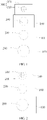
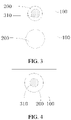
FIG. 1 to FIG. 4 are respectively schematic structural diagrams of a camera module according to an embodiment of the present invention in different states; -
FIG. 5 is a sectional view of a camera module according to an embodiment of the present invention; and -
FIG. 6 is a sectional view of a camera module according to an embodiment of the present invention in another state. - 100-First bracket, 200-Lens, 300-Camera assembly, 310-Camera, 320-Second bracket, 330-Lens, and 400-First driving mechanism.
- To make the objects, technical solutions, and advantages of the present invention clearer, the following clearly and completely describes the technical solutions of the present invention with reference to specific embodiments of the present invention and corresponding accompanying drawings. Apparently, the described embodiments are only some rather than all embodiments of the present invention. Based on the embodiments of the present invention, all other embodiments obtained by a person of ordinary skill in the art without creative efforts shall fall within the protection scope of the present invention.
- The technical solutions disclosed in the embodiments of the present invention are described in detail below with reference to the accompanying drawings.
- As shown in
FIG. 1 to FIG. 6 , an embodiment of the present invention discloses a camera module, and the disclosed camera module includes afirst bracket 100, alens 200, and acamera assembly 300. - The
first bracket 100 can provide a mounting position for another component of the camera module. Thefirst bracket 100 may be a frame-shaped structure or a plate-shaped structure. A specific structure of thefirst bracket 100 is not limited in this embodiment of the present invention. - The
lens 200 is one of important components of the camera module. In this embodiment of the present invention, thelens 200 is disposed on thefirst bracket 100. Optionally, a mounting hole may be disposed on thefirst bracket 100. Thelens 200 may be installed in the mounting hole through bonding, threaded connection, clamping, magnetic suction connection, or the like. Thelens 200 may be disposed in a removable structure, or may be disposed in a non-removable structure. Certainly, there are multiple manners in which thelens 200 is mounted on thefirst bracket 100. A specific manner of mounting thelens 200 on thefirst bracket 100 is not limited in this embodiment of the present invention. - The
camera assembly 300 includes acamera 310 and asecond bracket 320, and thecamera 310 is disposed on thesecond bracket 320. Optionally, thesecond bracket 320 may be a frame-shaped structural member. In this case, thecamera 310 may be disposed in an inner cavity of thesecond bracket 320. Correspondingly, an apparatus such as a circuit board for controlling thecamera 310 to shoot may also be disposed in the inner cavity of thesecond bracket 320, so that a structure of the camera module is relatively compact. Meanwhile, alens 330 opposite to thecamera 310 may also be disposed on a surface of thesecond bracket 320, so that thecamera assembly 300 can perform normal photographing, and thecamera 310 can be protected. - In this embodiment of the present invention, the
second bracket 320 and thefirst bracket 100 are slidably sleeved. In this case, thesecond bracket 320 and thefirst bracket 100 move relative to each other, so that thecamera 310 and thelens 200 can be in relative positions. In this way, thecamera 310 can face a working surface of thelens 200, and thecamera 310 captures an image at a far distance by using thelens 200. Certainly, an optical axis direction of thelens 200 is parallel to an optical axis direction of thecamera 310. - Specifically, at least one of the
camera 310 and thelens 200 may move between a first position and a second position. In other words, only a solution in which thecamera 310 or thelens 200 is movable may be used, or a solution in which both thecamera 310 and thelens 200 are movable may be used. In a case that thecamera 310 or thelens 200 is in the first position, a projection of thecamera 310 in the optical axis direction is staggered from a projection of thelens 200 in the optical axis direction. In a case that thecamera 310 or thelens 200 is in the second position, the projection of thecamera 310 in the optical axis direction at least partially overlaps the projection of thelens 200 in the optical axis direction. In an optional embodiment, in a photographing process, when a distance between a photographing subject and the camera module is relatively close, a user may control thecamera 310 or thelens 200 to move in a direction in which a relative distance between thelens 200 and thecamera 310 increases, so that the projection of thecamera 310 in the optical axis direction is staggered from the projection of thelens 200 in the optical axis direction. When the distance between the photographing subject and the camera module is relatively far, the user may control thecamera 310 or thelens 200 to move in a direction in which the relative distance between thelens 200 and thecamera 310 decreases, so that the projection of thecamera 310 in the optical axis direction at least partially overlaps the projection of thelens 200 in the optical axis direction, and finally, the camera module can shoot a clearer image of the photographing subject. - It can be learned from the foregoing content that, in the camera module disclosed in this embodiment of the present invention, in a case that the
camera 310 or thelens 200 is in the second position, the projection of thecamera 310 in the optical axis direction at least partially overlaps the projection of thelens 200 in the optical axis direction. In this case, light passes through thelens 200 first, and then enters thecamera 310, so that a high-multiple zooming function can be implemented. In this way, a photographing effect of the camera module is better, and a photographing requirement of the user can be finally satisfied. - In an embodiment disclosed in the present invention, there may be at least two
first brackets 100 and at least twolenses 200. Specifically, the at least twolenses 200 may be disposed in a one-to-one correspondence on the at least twofirst brackets 100, and the at least twofirst brackets 100 may be slidably sleeved in sequence. In this case, thesecond bracket 320 may be slidably sleeved with the at least twofirst brackets 100. In a photographing process, thesecond bracket 320 and the at least twofirst brackets 100 move relative to each other, so that the projection of thecamera 310 in the optical axis direction may at least partially overlap projections of the at least twolenses 200 in the optical axis direction. In this way, the camera module can implement a higher-multiple zooming function, and the camera module can shoot an image at a far distance. Certainly, this manner also makes the camera module more flexible. The camera module may adjust, based on a specific position of the photographing subject, a quantity oflenses 200 that face thecamera 310, so that the camera module can obtain a proper target focal length, and finally obtain a relatively clear image. - In this embodiment of the present invention, one of the
camera assembly 300 and thefirst bracket 100 may be disposed with a first limiting portion, and another may be disposed with a second limiting portion. Specifically, thesecond bracket 320 of thecamera assembly 300 may be disposed with the first limiting portion or the second limiting portion described herein. In a specific working process, in a case that thecamera 310 or thelens 200 is in the second position, the first limiting portion may cooperate with the second limiting portion through limiting, so that the projection of thecamera 310 in the optical axis direction may stably at least partially overlap the projection of thelens 200 in the optical axis direction, thereby preventing the projection of thecamera 310 in the optical axis direction from being staggered from the projection of thelens 200 in the optical axis direction and affecting a photographing effect of the camera module. - Correspondingly, in a case that there are at least two
first brackets 100 and at least twolenses 200, a third limiting portion may be disposed on one of two adjacentfirst brackets 100, and a fourth limiting portion may be disposed on the other. In this case, in the two adjacentfirst brackets 100, when a projection of alens 200 on one of thefirst brackets 100 in the optical axis direction at least partially overlaps a projection of alens 200 on the otherfirst bracket 100 in the optical axis direction, the third limiting portion and the fourth limiting portion may cooperate with each other through limiting, so that the twofirst brackets 100 can be maintained in the foregoing position, thereby preventing the projection of thelens 200 on one of thefirst brackets 100 in the optical axis direction and the projection of thelens 200 on otherfirst bracket 100 in the optical axis direction from being staggered and affecting a photographing effect of the camera module. - The first limiting portion and the second limiting portion may be in multiple specific structures. For example, one of the first limiting portion and the second limiting portion may be a slot, another of the first limiting portion and the second limiting portion may be a protrusion, and the slot and the protrusion may be limited; or at least one of the first limiting portion and the second limiting portion may be a magnetic suction part. In a case that the
camera 310 or thelens 200 is in the second position, the first limiting portion and the second limiting portion may be connected through magnetic suction. Certainly, the first limiting portion and the second limiting portion may further have multiple specific structures. Specific structures of the first limiting portion and the second limiting portion are not limited in the present invention. - Correspondingly, in a case that the
camera 310 or thelens 200 is in the first position, a corresponding limiting mechanism may also be disposed between thecamera assembly 300 and thefirst bracket 100, to prevent thecamera assembly 300 from being separated from thefirst bracket 100. In an optional solution, a first-gear protrusion may be disposed on one of thecamera assembly 300 and thefirst bracket 100, and a second-gear protrusion may be disposed on the other. In a case that thecamera 310 or thelens 200 is in the first position, the first-gear protrusion cooperates with the second-gear protrusion through limiting, to prevent thecamera assembly 300 from being separated from thefirst bracket 100. - In this embodiment disclosed in the present invention, the camera module may further include a
first driving mechanism 400. Specifically, thefirst driving mechanism 400 may be connected to thefirst bracket 100 or thesecond bracket 320. Optionally, thefirst driving mechanism 400 may be connected to thefirst bracket 100, so that thefirst driving mechanism 400 may drive thefirst bracket 100 to move, to enable thelens 200 to move between the first position and the second position. Thefirst driving mechanism 400 may also be connected to thesecond bracket 320, so that thefirst driving mechanism 400 may drive thesecond bracket 320 to move, to enable thecamera 310 to move between the first position and the second position. In a photographing process, thefirst driving mechanism 400 may drive thecamera 310 or thelens 200 to move between the first position and the second position, so that the camera module can easily implement a zooming function, thereby improving photographing experience of the user. - In this embodiment of the present invention, one of the
first bracket 100 and thesecond bracket 320 may be disposed with a sliding groove, another may be disposed with a sliding protrusion, and the sliding groove and the sliding protrusion may slidably cooperate with each other. In this case, in a process in which thefirst bracket 100 and thesecond bracket 320 move relative to each other, the sliding groove and the sliding protrusion can play a better guiding role, so that sliding between thefirst bracket 100 and thesecond bracket 320 is more stable, thereby preventing a jam phenomenon. In addition, the sliding groove and the sliding protrusion can further play a better limiting role, o prevent thefirst bracket 100 and thesecond bracket 320 from being staggered and affecting a photographing effect of the camera module. - Based on the camera module disclosed in this embodiment of the present invention, an electronic device is further disclosed in an embodiment of the present invention. The disclosed electronic device includes a device body and the camera module described in any one of the foregoing embodiments, and the camera module capable of being connected to the device body. The device body may include a housing, the housing is a peripheral component of the device body, and the housing can provide a mounting position for another component of the electronic device.
- Further, in this embodiment of the present invention, the electronic device may further include a second driving mechanism. The second driving mechanism is disposed inside the housing of the device body, and the second driving mechanism may be connected to the
first bracket 100 or thesecond bracket 320. In a specific photographing process, the second driving mechanism may drive thecamera 310 or thelens 200 to move between the first position and the second position, so that the camera module can easily implement a zooming function. Based on this, in an assembly process, at least portion of the camera module may be exposed outside the housing, so that the camera module may work outside the housing. The camera module may alternatively be disposed inside the housing. In this case, a transparent area may be disposed inside the housing, and the camera module may face the transparent area, so that the camera module may work inside the housing. - The foregoing
first driving mechanism 400 may also drive thecamera 310 or thelens 200 to move between the first position and the second position. Optionally, only thefirst driving mechanism 400 or the second driving mechanism may be disposed to implement movement of thecamera 310 or thelens 200, or both thefirst driving mechanism 400 and the second driving mechanism may be disposed. This is not limited in this embodiment of the present invention. - In an optional embodiment, the electronic device may further include a third driving mechanism, the housing of the device body may be provided with an opening, the third driving mechanism may be disposed inside the housing, and the third driving mechanism may be connected to the camera module. In a photographing process, the third driving mechanism may drive at least portion camera module to extend out of the housing or retract to the housing by using the opening. In this case, when a photographing function of the camera module needs to be used, the third driving mechanism may be controlled to drive at least portion the camera module to extend out of the housing through the opening, so that the camera module can work outside the housing, thereby improving the photographing effect of the camera module. When the photographing function of the camera module does not need to be used, the camera module may be located inside the housing. The camera module herein may implement front-facing photographing, or may implement rear-facing photographing. When the camera module implements front-facing photographing, the camera module does not occupy screen space of the electronic device, thereby increasing a screen-to-body ratio of the electronic device. When rear-facing photographing is implemented, a structure such as a transparent area does not need to be disposed on the housing corresponding to the camera module, to improve appearance quality of the electronic device, and in addition, a waterproof and dust-proof function can be implemented.
- Certainly, the
first driving mechanism 400, the second driving mechanism, and the third driving mechanism may be at least one of a hydraulic telescopic mechanism, a barometric telescopic mechanism, or a screw driving mechanism. Specific structures of thefirst driving mechanism 400, the second driving mechanism, and the second driving mechanism are not limited in the present invention. Optionally, when thefirst driving mechanism 400, the second driving mechanism, or the third driving mechanism is a screw driving mechanism, the screw driving mechanism may include a structure such as a motor, a screw, and a screw sleeve. The motor may drive the screw to rotate, and the screw sleeve is screwed with the screw, so that the screw may drive the screw sleeve to move, and the screw sleeve is connected to thefirst bracket 100, thesecond bracket 320, or the entire camera module, thereby driving thefirst bracket 100, thesecond bracket 320, or the entire camera module to move. - In an optional embodiment, the electronic device may have a first state and a second state. In a case that the electronic device is in the first state, the camera module may be separated from the device body. In this case, the camera module and the device body may independently work without mutual interference, or the device body may control the camera module to work by using a wireless module, so that the camera module can play a photographing function more freely. In a case that the electronic device is in the second state, the camera module capable of being connected to the device body. In this case, the device body and the camera module form a whole. The camera module may implement functions such as data transmission and charging by using the device body, or the device body may directly control the camera module to work.
- Based on the camera module disclosed in this embodiment of the present invention, an embodiment of the present invention further discloses a camera module control method, and the disclosed control method includes following steps.
- S 100: Obtain a target focal length of the camera module.
- The target focal length herein may be obtained based on a distance between the camera body and the
camera 310. - S200: Control the
camera 310 or thelens 200 to move between a first position and a second position based on the target focal length, so that an actual focal length of the camera module is equal to the target focal length. - After the target focal length of the camera module is obtained, the
camera 310 or thelens 200 may be controlled to move between the first position and the second position, and thecamera 310 cooperates with thelens 200, so that the actual focal length of the camera module is equal to the target focal length, to enable the camera module to obtain a relatively clear image. - In the foregoing control method, in a case that the
camera 310 or thelens 200 is in the second position, a projection of thecamera 310 in an optical axis direction at least partially overlaps a projection of thelens 200 in the optical axis direction. In this case, light passes through thelens 200 first, and then enters thecamera 310, so that a high-multiple zooming function can be implemented. In this way, a photographing effect of the camera module is better, and a photographing requirement of a user can be finally satisfied. - To facilitate the user to use the camera module, step S100 specifically includes following steps.
- S110: Receive a first input performed by a user, where the first input is used to trigger a photographing operation.
- S 120: In response to the first input, perform scene recognition on an environment in which a photographing subject is located, to obtain the target focal length that matches a recognized scene.
- Specifically, in a process in which a user uses the camera module, the user may first trigger a photographing operation by clicking a photographing button or the like. In this case, the camera module may receive a first input performed by the user, and after obtaining the first input performed by the user, the camera module may perform scene recognition on the environment in which the photographing subject is located. In an optional solution, a human-machine interaction interface may be disposed on the camera module, and the user may enter a corresponding parameter on the human-machine interaction interface, so that the electronic device may perform, based on this parameter, scene recognition on the environment in which the photographing subject is located. In another optional solution, a sensing module may be disposed on the camera module, and the camera module may perform scene identification on the photographing subject by using the sensing module. Further, a correspondence table between the recognized scenario and the target focal length may be pre-stored on the electronic device. After a scene recognition operation is implemented, the target focal length that matches the recognized scenario may be obtained according to the correspondence table.
- To enable the camera module to implement a higher-multiple zooming function, in an optional solution, there may be at least two
first brackets 100 and at least twolenses 200, the at least twolenses 200 are disposed in a one-to-one correspondence on the at least twofirst brackets 100, the at least twofirst brackets 100 may be slidably sleeved in sequence, and an optical axis direction of thelens 200 is parallel to an optical axis direction of thecamera 310. In this case, step S200 may specifically include following steps. - S210: Detect whether the actual focal length of the camera module is equal to the target focal length.
- When the
camera 310 and thelens 200 do not move relative to each other, the actual focal length may be different from the target focal length, and therefore, step S210 may be implemented. When thecamera 310 and thelens 200 have moved relative to each other, but do not move in place, the foregoing actual focal length may be different from the target focal length, and therefore, step S210 may also be implemented. - S220: In a case that the actual focal length is not equal to the target focal length, detect whether a projection of each
lens 200 in an optical axis direction is staggered from a projection of thecamera 310 in the optical axis direction. - S230: In a case that the projection of each
lens 200 in the optical axis direction is staggered from the projection of thecamera 310 in the optical axis direction, control at least onelens 200 or thecamera 310 to move in a first direction. - S240: In a case that a projection of at least one
lens 200 in the optical axis direction at least partially overlaps the projection of thecamera 310 in the optical axis direction, detect whether the projection of eachlens 200 in the optical axis direction at least partially overlaps the projection of thecamera 310 in the optical axis direction. - S250: In a case that the projection of each
lens 200 in the optical axis direction at least partially overlaps the projection of thecamera 310 in the optical axis direction, control the at least onelens 200 or thecamera 310 to move in a second direction. - S260: In a case that a projection of the at least one
lens 200 in the optical axis direction is staggered from the projection of thecamera 310 in the optical axis direction, control the at least onelens 200 or thecamera 310 to move in the first direction or the second direction. - It should be noted that the first direction is a direction in which a relative distance between the
lens 200 and thecamera 310 decreases, that is, a direction in which thelens 200 and thecamera 310 approach each other, and the second direction is opposite to the first direction, that is, a direction in which the relative distance between thelens 200 and thecamera 310 increases. When the foregoing solution is used, a state of the camera module may be more accurately controlled, to improve a photographing effect of the camera module. - Based on the control method in any one of the foregoing embodiments, an embodiment of the present invention further provides an electronic device. The electronic device may include:
- an obtaining module, configured to obtain a target focal length of a camera module; and
- a control module, configured to control a
camera 310 or alens 200 to move between a first position and a second position based on the target focal length, so that an actual focal length of the camera module is equal to the target focal length. - Further, with reference to the foregoing description, to enable the camera module to accurately obtain the target focal length, the obtaining module may include a receiving unit and a scene recognition unit. The receiving unit is configured to receive a first input performed by a user, and the scene recognition unit is configured to perform, in response to the first input, scene recognition on an environment in which a photographing subject is located, to obtain the target focal length that matches a recognized scene.
- To enable the camera module to implement a higher-multiple zooming function, the control module may include:
- a first detection unit, configured to detect whether the actual focal length of the camera module is equal to the target focal length;
- a second detection unit, configured to: in a case that the actual focal length is not equal to the target focal length, detect whether a projection of each
lens 200 in an optical axis direction is staggered from a projection of thecamera 310 in the optical axis direction; - a first control unit, configured to: in a case that the projection of each
lens 200 in the optical axis direction is staggered from the projection of thecamera 310 in the optical axis direction, control at least onelens 200 or thecamera 310 to move in a first direction; - a third detection unit, configured to: in a case that a projection of at least one
lens 200 in the optical axis direction at least partially overlaps the projection of thecamera 310 in the optical axis direction, detect whether the projection of eachlens 200 in the optical axis direction at least partially overlaps the projection of thecamera 310 in the optical axis direction; - a second control unit, configured to: in a case that the projection of each
lens 200 in the optical axis direction at least partially overlaps the projection of thecamera 310 in the optical axis direction, control at least onelens 200 or thecamera 310 to move in a second direction; and - a fourth control unit, configured to: in a case that the projection of at least one
lens 200 in the optical axis direction at least partially overlaps the projection of thecamera 310 in the optical axis direction, control the at least onelens 200 or thecamera 310 to move in the first direction or the second direction. - The first direction is a direction in which a relative distance between the
lens 200 and thecamera 310 decreases, and the second direction is opposite to the first direction, that is, a direction in which the relative distance between thelens 200 and thecamera 310 increases. - An embodiment of the present invention further discloses an electronic device, including a processor, a memory, and a computer program that is stored in the memory and that can run on the processor. When the computer program is executed by the processor, steps of the control method in any one of the foregoing embodiments are implemented.
- An embodiment of the present invention further discloses a computer-readable storage medium, where the computer-readable storage medium stores a computer program, and when the computer program is executed by a processor, steps of the control method in any one of the foregoing embodiments are implemented.
- The processor is a processor in the electronic device in the foregoing embodiment. The readable storage medium includes a computer-readable storage medium such as a read-only memory (Read-Only Memory, ROM), a random access memory (Random Access Memory, RAM), a magnetic disk, an optical disc, or the like.
- The electronic device disclosed in the embodiments of the present invention may be a device such as a smartphone, a tablet computer, an e-book reader, a wearable device (for example, a smart watch), or a video game. A specific type of the electronic device is not limited in the embodiments of the present invention.
- The foregoing embodiments of the present invention focus on describing differences between the embodiments, and different optimization features of the embodiments may be combined to form better embodiments provided that they are not contradictory. Considering brevity, details are not described herein again.
- The foregoing descriptions are merely embodiments of the present invention, and are not intended to limit the present invention. For a person skilled in the art, various changes and variations may be made in the present invention. Any modification, equivalent replacement, and improvement made in the spirit and principles of the present invention shall be included in the scope of the claims of the present invention.
Claims (15)
- A camera module, comprising:a first bracket;a lens, wherein the lens is disposed on the first bracket; anda camera assembly, wherein the camera assembly comprises a camera and a second bracket, the camera is disposed on the second bracket, the second bracket is slidably sleeved with the first bracket, and an optical axis direction of the lens is parallel to an optical axis direction of the camera; whereinat least one of the camera and the lens is movable between a first position and a second position; in a case that the camera or the lens is in the first position, a projection of the camera in the optical axis direction is staggered from a projection of the lens in the optical axis direction; and in a case that the camera or the lens is in the second position, the projection of the camera in the optical axis direction at least partially overlaps the projection of the lens in the optical axis direction.
- The camera module according to claim 1, wherein there are at least two first brackets and at least two lenses, the at least two lenses are disposed in a one-to-one correspondence on the at least two first brackets, and the at least two first brackets are slidably sleeved in sequence.
- The camera module according to claim 1 or 2, wherein one of the camera assembly and the first bracket is disposed with a first limiting portion, another is disposed with a second limiting portion, and in a case that the camera is in the second position, the first limiting portion cooperates with the second limiting portion through limiting.
- The camera module according to any one of claims 1 to 3, further comprising a first driving mechanism, wherein the first driving mechanism is connected to the first bracket or the second bracket, and the first driving mechanism drive the camera or the lens to move between the first position and the second position.
- The camera module according to any one of claims 1 to 4, wherein one of the first bracket and the second bracket is disposed with a sliding groove, another is disposed with a sliding protrusion, and the sliding groove slidably matches the sliding protrusion.
- An electronic device, comprising a device body and the camera module according to any one of claims 1 to 5, wherein the camera module capable of being connected to the device body.
- The electronic device according to claim 6, further comprising a second driving mechanism, wherein the device body comprises a housing, the second driving mechanism is disposed inside the housing, the second driving mechanism is connected to the first bracket or the second bracket, and the second driving mechanism drive the camera or the lens to move between the first position and the second position.
- The electronic device according to claim 6 or 7, further comprising a third driving mechanism, wherein the device body comprises a housing, the housing is provided with an opening, the third driving mechanism is disposed inside the housing, the third driving mechanism is connected to the camera module, and the third driving mechanism drive at least portion the camera module to extend out of the housing or retract to the housing through the opening.
- The electronic device according to any one of claims 6 to 8, wherein the electronic device has a first state and a second state, and in a case that the electronic device is in the first state, the camera module is separated from the device body; and in a case that the electronic device is in the second state, the camera module is connected to the device body.
- A camera module control method, wherein the method is applied to the camera module according to any one of claims 1 to 9, and the control method comprises:obtaining a target focal length of the camera module; andcontrolling, based on the target focal length, the camera or the lens to move between the first position and the second position, so that an actual focal length of the camera module is equal to the target focal length.
- The control method according to claim 10, wherein the obtaining the target focal length of the camera module specifically comprises:receiving a first input performed by a user, wherein the first input is used to trigger a photographing operation; andin response to the first input, performing scene recognition on an environment in which a photographing subject is located, to obtain the target focal length that matches a recognized scene.
- The control method according to claim 10 or 11, wherein there are at least two first brackets and at least two lenses, the at least two lenses are disposed in a one-to-one correspondence on the at least two first brackets, the at least two first brackets are slidably sleeved in sequence, and an optical axis direction of the lens is parallel to an optical axis direction of the camera; and
the controlling, based on the target focal length, the camera or the lens to move between the first position and the second position, so that the actual focal length of the camera module is equal to the target focal length comprises:detecting whether the actual focal length of the camera module is equal to the target focal length;in a case that the actual focal length is not equal to the target focal length, detecting whether a projection of each lens in the optical axis direction is staggered from a projection of the camera in the optical axis direction;in a case that the projection of each lens in the optical axis direction is staggered from the projection of the camera in the optical axis direction, controlling at least one lens or the camera to move in a first direction;in a case that a projection of at least one lens in the optical axis direction at least partially overlaps the projection of the camera in the optical axis direction, detecting whether the projection of each lens in the optical axis direction at least partially overlaps the projection of the camera in the optical axis direction;in a case that the projection of each lens in the optical axis direction at least partially overlaps the projection of the camera in the optical axis direction, controlling at least one lens or the camera to move in a second direction; andin a case that the projection of at least one lens in the optical axis direction is staggered from the projection of the camera in the optical axis direction, controlling at least one lens or the camera to move in the first direction or the second direction; whereinthe first direction is a direction in which a relative distance between the lens and the camera decreases, and the second direction is opposite to the first direction. - An electronic device, comprising: a memory, a processor, and a computer program that is stored in the memory and that can run on the processor, wherein when the computer program is executed by the processor, steps in the control method according to any one of claims 10 to 12 are implemented.
- A control device, comprising the device configured to perform the control method according to any one of claims 10 to 12.
- A readable storage medium, wherein the readable storage medium stores a program or an instruction, and when the program or the instruction is executed by a processor, steps of the control method according to any one of claims 10 to 12 are implemented.
Applications Claiming Priority (2)
| Application Number | Priority Date | Filing Date | Title |
|---|---|---|---|
| CN202010076068.3A CN111263041B (en) | 2020-01-22 | 2020-01-22 | Camera module, electronic equipment and control method of camera module |
| PCT/CN2021/072904 WO2021147912A1 (en) | 2020-01-22 | 2021-01-20 | Camera module, electronic device, and camera module control method |
Publications (2)
| Publication Number | Publication Date |
|---|---|
| EP4089998A1 true EP4089998A1 (en) | 2022-11-16 |
| EP4089998A4 EP4089998A4 (en) | 2023-07-26 |
Family
ID=70951018
Family Applications (1)
| Application Number | Title | Priority Date | Filing Date |
|---|---|---|---|
| EP21743729.2A Pending EP4089998A4 (en) | 2020-01-22 | 2021-01-20 | CAMERA MODULE, ELECTRONIC DEVICE AND CAMERA MODULE CONTROL METHOD |
Country Status (5)
| Country | Link |
|---|---|
| US (1) | US12126909B2 (en) |
| EP (1) | EP4089998A4 (en) |
| JP (1) | JP7476314B2 (en) |
| CN (1) | CN111263041B (en) |
| WO (1) | WO2021147912A1 (en) |
Families Citing this family (5)
| Publication number | Priority date | Publication date | Assignee | Title |
|---|---|---|---|---|
| CN111263041B (en) * | 2020-01-22 | 2021-07-20 | 维沃移动通信有限公司 | Camera module, electronic equipment and control method of camera module |
| CN112422787B (en) * | 2020-10-28 | 2022-04-22 | 维沃移动通信有限公司 | Camera module and electronic equipment |
| CN112637461B (en) * | 2020-12-21 | 2022-08-19 | 维沃移动通信有限公司 | Electronic equipment and camera module |
| CN113676642A (en) * | 2021-08-17 | 2021-11-19 | Oppo广东移动通信有限公司 | Camera assembly and its control method, electronic device |
| CN113676648B (en) * | 2021-08-23 | 2023-08-22 | 南昌逸勤科技有限公司 | Multifunctional camera system and electronic equipment |
Family Cites Families (15)
| Publication number | Priority date | Publication date | Assignee | Title |
|---|---|---|---|---|
| US3882269A (en) * | 1973-05-11 | 1975-05-06 | Scripps Co E W | Apparatus, system and method of storing a static image displayed on a television tube |
| US4215373A (en) * | 1978-10-19 | 1980-07-29 | Goldenberg David A | Television set projector |
| JPH0490529A (en) * | 1990-08-02 | 1992-03-24 | Canon Inc | Focal distance switching device for camera |
| JP4292795B2 (en) * | 2002-12-13 | 2009-07-08 | 富士フイルム株式会社 | Mobile device with camera |
| TWI244306B (en) * | 2003-11-06 | 2005-11-21 | Benq Corp | Mobile phone and digital camera thereof |
| JP2005284247A (en) * | 2004-02-23 | 2005-10-13 | Fujinon Corp | Lens barrel, photographic apparatus, and optical apparatus |
| TWM326650U (en) * | 2007-07-27 | 2008-02-01 | Lumos Technology Co Ltd | Cartridge-type appendix lens for digital camera |
| JP4949499B2 (en) | 2010-03-17 | 2012-06-06 | 株式会社リコー | Lens barrel, camera using the lens barrel, and portable information terminal device |
| US10218905B2 (en) * | 2013-03-06 | 2019-02-26 | Nokia Technologies Oy | Sliding accessory lens mount with automatic mode adjustment |
| JP5527492B1 (en) * | 2013-08-19 | 2014-06-18 | ソニー株式会社 | Imaging apparatus, control method, and program |
| CN204733195U (en) * | 2015-05-08 | 2015-10-28 | 深圳旺科知识产权运营中心有限公司 | Multistage zoom mobile phone camera |
| JP2019012149A (en) * | 2017-06-29 | 2019-01-24 | キヤノン株式会社 | Lens device and imaging device having the same |
| CN208739253U (en) * | 2018-10-24 | 2019-04-12 | 北京小米移动软件有限公司 | Camera module and electronic equipment |
| CN110445918B (en) * | 2019-08-22 | 2024-07-16 | 维沃移动通信有限公司 | Mobile Terminal |
| CN111263041B (en) * | 2020-01-22 | 2021-07-20 | 维沃移动通信有限公司 | Camera module, electronic equipment and control method of camera module |
-
2020
- 2020-01-22 CN CN202010076068.3A patent/CN111263041B/en active Active
-
2021
- 2021-01-20 WO PCT/CN2021/072904 patent/WO2021147912A1/en not_active Ceased
- 2021-01-20 JP JP2022539634A patent/JP7476314B2/en active Active
- 2021-01-20 EP EP21743729.2A patent/EP4089998A4/en active Pending
-
2022
- 2022-07-18 US US17/866,826 patent/US12126909B2/en active Active
Also Published As
| Publication number | Publication date |
|---|---|
| WO2021147912A1 (en) | 2021-07-29 |
| US12126909B2 (en) | 2024-10-22 |
| EP4089998A4 (en) | 2023-07-26 |
| JP2023508487A (en) | 2023-03-02 |
| CN111263041A (en) | 2020-06-09 |
| US20220353421A1 (en) | 2022-11-03 |
| JP7476314B2 (en) | 2024-04-30 |
| CN111263041B (en) | 2021-07-20 |
Similar Documents
| Publication | Publication Date | Title |
|---|---|---|
| US12126909B2 (en) | Camera module, electronic device, and method for controlling camera module | |
| US9069407B2 (en) | Display control apparatus and display control method | |
| TWI672538B (en) | Camera module and electronic device | |
| CN101753815B (en) | Imaging apparatus | |
| US10571777B2 (en) | Imaging apparatus | |
| TWI660229B (en) | Lens driving module, photographing system and cell phone device | |
| US20180324351A1 (en) | Control device, control method, and program | |
| US11867925B2 (en) | Driving mechanism for optical element | |
| JP7404563B2 (en) | Image acquisition methods, equipment and electronics | |
| CN114071025B (en) | Camera assembly, electronic equipment and control method and device thereof | |
| WO2020038063A1 (en) | Electronic device and control method for electronic device | |
| US20210357027A1 (en) | Electronic device and control method thereof | |
| US20190289177A1 (en) | Electronic device and operating method thereof | |
| US11876919B2 (en) | Terminal device | |
| WO2023022438A1 (en) | Camera module comprising folded optical system | |
| US10336021B2 (en) | Imaging lens element, camera module, and electronic device | |
| US20210088697A1 (en) | Liquid iris, optical device comprising same, and mobile terminal | |
| CN219392350U (en) | Imaging lens and electronic device | |
| KR102080656B1 (en) | Camera module | |
| KR20230094913A (en) | Method of removing interference and electronic device performing the method | |
| KR20230065049A (en) | Wearable electronic apparatus and method for controlling electronic devices using vision information | |
| CN113364982A (en) | Image generation method, device, equipment and storage medium based on LCD liquid crystal device | |
| JP2018023068A (en) | Electronic device, control method thereof, and program | |
| CN110381241A (en) | Camera module, mobile terminal and control method thereof | |
| CN120405968B (en) | Intelligent glasses and control method thereof |
Legal Events
| Date | Code | Title | Description |
|---|---|---|---|
| STAA | Information on the status of an ep patent application or granted ep patent |
Free format text: STATUS: THE INTERNATIONAL PUBLICATION HAS BEEN MADE |
|
| PUAI | Public reference made under article 153(3) epc to a published international application that has entered the european phase |
Free format text: ORIGINAL CODE: 0009012 |
|
| STAA | Information on the status of an ep patent application or granted ep patent |
Free format text: STATUS: REQUEST FOR EXAMINATION WAS MADE |
|
| 17P | Request for examination filed |
Effective date: 20220808 |
|
| AK | Designated contracting states |
Kind code of ref document: A1 Designated state(s): AL AT BE BG CH CY CZ DE DK EE ES FI FR GB GR HR HU IE IS IT LI LT LU LV MC MK MT NL NO PL PT RO RS SE SI SK SM TR |
|
| DAV | Request for validation of the european patent (deleted) | ||
| DAX | Request for extension of the european patent (deleted) | ||
| REG | Reference to a national code |
Ref country code: DE Ref legal event code: R079 Free format text: PREVIOUS MAIN CLASS: H04N0005225000 Ipc: G03B0017000000 |
|
| A4 | Supplementary search report drawn up and despatched |
Effective date: 20230623 |
|
| RIC1 | Information provided on ipc code assigned before grant |
Ipc: G03B 30/00 20210101ALI20230619BHEP Ipc: H04N 23/62 20230101ALI20230619BHEP Ipc: H04N 23/61 20230101ALI20230619BHEP Ipc: G03B 5/00 20210101ALI20230619BHEP Ipc: H04N 23/69 20230101ALI20230619BHEP Ipc: H04N 23/55 20230101ALI20230619BHEP Ipc: H04N 23/51 20230101ALI20230619BHEP Ipc: G03B 17/04 20210101ALI20230619BHEP Ipc: G02B 15/02 20060101ALI20230619BHEP Ipc: G03B 17/00 20210101AFI20230619BHEP |
|
| STAA | Information on the status of an ep patent application or granted ep patent |
Free format text: STATUS: EXAMINATION IS IN PROGRESS |
|
| 17Q | First examination report despatched |
Effective date: 20241009 |