EP4089933B1 - Verfahren und vorrichtung zur beschleunigten schätzung eines funkmodells eines strahlformungszugriffspunktes - Google Patents
Verfahren und vorrichtung zur beschleunigten schätzung eines funkmodells eines strahlformungszugriffspunktes Download PDFInfo
- Publication number
- EP4089933B1 EP4089933B1 EP22172691.2A EP22172691A EP4089933B1 EP 4089933 B1 EP4089933 B1 EP 4089933B1 EP 22172691 A EP22172691 A EP 22172691A EP 4089933 B1 EP4089933 B1 EP 4089933B1
- Authority
- EP
- European Patent Office
- Prior art keywords
- access point
- radio
- model
- points
- beams
- Prior art date
- Legal status (The legal status is an assumption and is not a legal conclusion. Google has not performed a legal analysis and makes no representation as to the accuracy of the status listed.)
- Active
Links
Images




Classifications
-
- H—ELECTRICITY
- H04—ELECTRIC COMMUNICATION TECHNIQUE
- H04B—TRANSMISSION
- H04B17/00—Monitoring; Testing
- H04B17/30—Monitoring; Testing of propagation channels
- H04B17/391—Modelling the propagation channel
- H04B17/3912—Simulation models, e.g. distribution of spectral power density or received signal strength indicator [RSSI] for a given geographic region
-
- H—ELECTRICITY
- H04—ELECTRIC COMMUNICATION TECHNIQUE
- H04B—TRANSMISSION
- H04B17/00—Monitoring; Testing
- H04B17/30—Monitoring; Testing of propagation channels
- H04B17/309—Measuring or estimating channel quality parameters
- H04B17/318—Received signal strength
-
- H—ELECTRICITY
- H04—ELECTRIC COMMUNICATION TECHNIQUE
- H04W—WIRELESS COMMUNICATION NETWORKS
- H04W16/00—Network planning, e.g. coverage or traffic planning tools; Network deployment, e.g. resource partitioning or cells structures
- H04W16/24—Cell structures
- H04W16/28—Cell structures using beam steering
-
- H—ELECTRICITY
- H04—ELECTRIC COMMUNICATION TECHNIQUE
- H04W—WIRELESS COMMUNICATION NETWORKS
- H04W24/00—Supervisory, monitoring or testing arrangements
- H04W24/04—Arrangements for maintaining operational condition
-
- H—ELECTRICITY
- H04—ELECTRIC COMMUNICATION TECHNIQUE
- H04W—WIRELESS COMMUNICATION NETWORKS
- H04W24/00—Supervisory, monitoring or testing arrangements
- H04W24/10—Scheduling measurement reports ; Arrangements for measurement reports
-
- H—ELECTRICITY
- H04—ELECTRIC COMMUNICATION TECHNIQUE
- H04B—TRANSMISSION
- H04B7/00—Radio transmission systems, i.e. using radiation field
- H04B7/02—Diversity systems; Multi-antenna system, i.e. transmission or reception using multiple antennas
- H04B7/04—Diversity systems; Multi-antenna system, i.e. transmission or reception using multiple antennas using two or more spaced independent antennas
- H04B7/06—Diversity systems; Multi-antenna system, i.e. transmission or reception using multiple antennas using two or more spaced independent antennas at the transmitting station
- H04B7/0613—Diversity systems; Multi-antenna system, i.e. transmission or reception using multiple antennas using two or more spaced independent antennas at the transmitting station using simultaneous transmission
- H04B7/0615—Diversity systems; Multi-antenna system, i.e. transmission or reception using multiple antennas using two or more spaced independent antennas at the transmitting station using simultaneous transmission of weighted versions of same signal
- H04B7/0617—Diversity systems; Multi-antenna system, i.e. transmission or reception using multiple antennas using two or more spaced independent antennas at the transmitting station using simultaneous transmission of weighted versions of same signal for beam forming
Definitions
- the radio models may then be utilized to determine the position of a mobile device. For example, while a mobile device is at an unknown location, the mobile device may capture measurements of the cellular or non-cellular signals transmitted by the access points. By reference to the radio models that have been constructed, the measurements of the radio signals may be evaluated and the location of the mobile terminal may be determined, such as based upon the coverage areas of the access points.
- US 2019/306662 A1 discloses a method in which beam-forming and non-beam-forming access points are distinguished for localization purposes.
- WO 2021 006796 A1 discloses a method for localizing a UE wherein beams are distinguished into two groups by different means.
- the dynamic nature of the coverage model of a beamforming node creates challenges with respect to the generation of a radio model that is based upon radio fingerprints collected by mobile devices at different points in time based upon the radio signals transmitted by the beamforming node.
- the radio fingerprints collected by a mobile device at the same location relative to a beamforming mode may be different at different points in time because of the changes in the coverage model of the beamforming node.
- the accuracy and reliability of the resulting radio model may be reduced in instances in which the wireless communication nodes include one or more beamforming nodes due to the changing nature of the coverage model of a beamforming node.
- the location of a beamforming node that is estimated based on the radio fingerprints including the signal strength values of the radio signals transmitted by the beamforming node may also be less accurate due to the dynamic nature of the coverage model relative to a wireless communication node having a static coverage model.
- radio environments change over time as access points are added, moved, e.g., relocated, or removed.
- access points such as WLAN access points
- WLAN access points it may not be uncommon for access points, such as WLAN access points, to be added or removed from the radio environment.
- These changes in the radio environment brought about by the addition, movement or removal of an access point alter the resulting radio models that are present within the radio environment.
- the addition of an access point adds a further radio model to the radio environment and the movement of an access point changes an existing radio model within the radio environment.
- the radio models In order to ensure that the radio models can be utilized in an accurate manner, such as to determine the position of a mobile terminal within the radio environment, the radio models must be redefined or updated as access points are added, moved or removed within the radio environment since the radio model database otherwise becomes out of date.
- the creation of a new radio model for an access point that is added to a radio environment or the updating of a radio model for an access point that is moved within the radio environment may take some time in order to accumulate sufficient probe points from the respective access points such that the radio model can be accurately defined or updated.
- This delay in creating a new radio model or updating a radio model may be particularly substantial in an instance in which the access point that is added or moved is a beamforming access point for which the coverage model changes over time.
- the radio model for the access point that has been added or moved is being defined or updated, the radio models that are utilized to determine the position of a mobile terminal may be outdated, such as in an instance in which an access point has moved or been relocated, or incomplete, such as in an instance in which an access point has been added to the radio environment.
- the utilization of the radio models of the access points within the radio environment may not yield results that are as accurate as may be desired in an instance in which a radio model is being newly defined or updated, thereby potentially leading to a reduction in confidence in the resulting positions determinations.
- a method and an apparatus as specified by independent claims 1 and 9 are provided in accordance with an example embodiment in order to accelerate the estimation of the radio model of a beamforming access point within a radio environment, such as a beamforming access point that has been newly added to the radio environment or a beamforming access point that is been moved or relocated within the radio environment.
- the radio model that is estimated in accordance with an example embodiment may not only be more quickly defined, but may be defined with enhanced accuracy relative to radio models that are defined on the basis of only a few probe points.
- the radio model that is estimated by the method, apparatus and computer program product of an example embodiment may be utilized to reliably determine the position of a mobile terminal within the radio environment.
- a method for accelerating estimation of a radio model of a first access point.
- the method includes determining a presence of the first access point in a radio environment.
- the method also includes determining that the first access point is a beamforming node and obtaining information regarding one or more of a plurality of beams.
- the plurality of beams are transmitted by the first access point.
- the method further includes estimating the radio model of the first access point based at least upon: (i) at least some of the information regarding the one or more of the beams transmitted by the first access point and (ii) signal propagation characteristics of one or more existing access points in the radio environment as represented by respective radio models of the one or more existing access points.
- the method of an example embodiment determines the presence of the first access point by determining the presence of the first access point based at least upon a first probe point representative of radio signals transmitted by a respective beam from among the plurality of beams transmitted by the first access point.
- the method obtains information regarding the one or more of the plurality of beams transmitted by the first access point by obtaining information regarding a total number of beams and an identification of the respective beam of the first access point providing the radio signals of which the first probe point is representative.
- the method may also estimate the radio model of the first access point by orienting the radio model of the first access point based at least in part upon the identification of the respective beam of the first access point in relation to the total number of beams of the first access point. Additionally or alternatively, the method may also include receiving information regarding a second probe point representative of radio signals transmitted by another beam of the plurality of beams transmitted by the first access point. In this example embodiment, the method estimates the radio model of the first access point by orienting the radio model of the first access point based at least in part upon relative positions of the respective beam and the another beam in relation to the total number of beams of the first access point. The method may also include receiving information regarding a second probe point representative of the radio signals transmitted in the respective beam of the first access point.
- the first and second probe points are associated with different respective locations and provide information regarding a signal strength of the radio signals transmitted in the respective beam of the first access point and received at the respective location. Additionally, the method of this example embodiment estimates the radio model of the first access point by estimating the radio model of the first access point based at least in part upon the signal strength of the radio signals represented by the first probe point and the signal strength of the radio signals represented by the second probe point.
- the method of an example embodiment estimates the radio model of the first access point by estimating the radio model of the first access point based upon at least one of a size or shape of the respective radio models of the one or more existing access points. In an example embodiment, the method estimates the radio model of the first access point by estimating the radio model of the first access point based upon at least a shape of the respective radio models of the one or more existing access points relative to an obstacle within the radio environment. In this example embodiment, the obstacle includes an obstacle to signal propagation within the radio environment. The method of an example embodiment determines that the first access point is a beamforming node by detecting that the first access point employs beam sweeping to alter signal strengths of the plurality of beams transmitted by the first access point over time.
- an apparatus configured to accelerate estimation of a radio model of a first access point.
- the apparatus includes processing circuitry and at least one memory including computer program code instructions with the computer program code instructions configured to, when executed by the processing circuity, cause the apparatus to determine a presence of the first access point in a radio environment.
- the computer program code instructions are also configured to, when executed by the processing circuity, cause the apparatus to determine that the first access point is a beamforming node and to obtain information regarding one or more of a plurality of beams. The plurality of beams are transmitted by the first access point.
- the computer program code instructions are further configured to, when executed by the processing circuity, cause the apparatus to estimate the radio model of the first access point based at least upon: (i) at least some of the information regarding the one or more of the beams transmitted by the first access point and (ii) signal propagation characteristics of one or more existing access points in the radio environment as represented by respective radio models of the one or more existing access points.
- a method and apparatus are provided in accordance with an example embodiment in order to accelerate the estimation of the radio model of a beamforming access point within a radio environment.
- the beamforming access point is configured to transmit radio signals having a variable or dynamic coverage model that changes over time such that the radio model that is estimated is correspondingly reflective of the variable or dynamic coverage model.
- the beamforming access point may be any of a variety of different types of access points including an access point, Node B, enhanced Node B (eNB) or the like, such as for a cellular system, e.g., a 5G cellular system, or a non-cellular network, e.g., an 802.11 WiFi network.
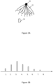
- Figure 3A depicts a beamforming access point 20 having a phased array of antennas for transmitting and receiving radio signals.
- the radio beams 22 sequentially generated by the beamforming access point at eight different points in time are illustrated and designated 1, 2, ... 8.
- all eight beams are depicted in a composite view.
- the beamforming access point of one embodiment will only transmit one (or a subset) of the beams at any one point in time, while the beamforming access point of another embodiment will preferentially transmit only one (or a subset) of the beams such that the preferred one (or subset) of the beams has a greater power than signals transmitted by the other beams.
- the beamforming access point sweeps the beam by sequentially advancing from transmission of one beam to the next until all of the beams have been transmitted, or preferentially transmitted, in a relatively short period of time while the position of the beamforming access point remains the same or virtually the same. As shown, the beamforming access point sweeps the beam such that the beam of radio signals generated at each different point in time is different from the beams of radio signals generated at other points in time, at least in terms of the direction and corresponding coverage area of the beams of radio signals.
- the mobile device may include any of a wide variety of mobile terminals such as a mobile telephone, a smart phone, a personal digital assistant (PDA), a personal navigation device, a smart watch, a tablet computer, or any combination of the aforementioned and other types of portable computer devices.
- a mobile telephone such as a mobile telephone, a smart phone, a personal digital assistant (PDA), a personal navigation device, a smart watch, a tablet computer, or any combination of the aforementioned and other types of portable computer devices.
- PDA personal digital assistant
- the radio signals received by the mobile node not only identify the beamforming access point, but may also identify the antenna configuration that is currently active such that the different beams may be distinguished.
- the signal strength from the third beam of radio signals is greater than the signal strengths of any of the other beams of radio signals generated by the same beamforming access point since the position of the mobile device is more closely aligned with the third beam of radio signals as shown in Figure 3A .
- the access point for which the radio model is estimated may be a beamforming access point that is newly added to the radio environment, that is, a beamforming access point that was not previously present within the radio environment and was not previously transmitting radio signals throughout the radio environment.
- the access point for which the radio model is estimated may be a beamforming access point that was previously part of the radio environment, such as by being previously present within the radio environment and transmitting radio signals throughout the radio environment, but that has been moved or relocated within the radio environment.
- the beamforming access point for which the radio model is estimated may be an access point for a cellular-based radio environment, such as a base station, or for a non-cellular radio environment, such as a WLAN access point or other type of non-cellular access point. Additionally, the beamforming access point for which the radio model is estimated and the radio environment in which the access point is disposed may be outdoors, such as in an instance in which the access point is a base station of a cellular-based radio environment, or indoors, such as in an instance in which the access point is a WLAN access point or other type of non-cellular access point.
- the method, apparatus and computer program product of an example embodiment will hereinafter be described in conjunction with a radio environment that is indoors with the beamforming access point for which the radio model is estimated also being indoors, such as a WLAN access point or other non-cellular access point.
- the radio environment into which the beamforming access point is added or within which the beamforming access point is relocated also includes one or more existing access points that are configured to transmit radio signals throughout the radio environment and for which radio models have been defined.
- the existing access point(s) may also be beamforming access point(s) or may be access point(s) having a static coverage model or may be some combination thereof.
- the access point for which a radio model is estimated in accordance with an example embodiment is added to the radio environment or is moved within the radio environment after the radio models of the existing access points have been defined, such as based on probe points collected for the existing access points.
- the access point for which a radio model is estimated and the existing access points may be the same type of access points, such as base stations or other cellular-based access points or a WLAN access point or other non-cellular access points.
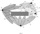
- Figure 4 depicts a radio environment that includes three existing access points 30 designated A, B and C.
- a radio model 32 has been defined for each of the existing access points.
- the radio models of the existing access points illustrate the region within which radio signals transmitted by a respective access point can be detected with at least predefined signal characteristics, such as at least a predefined signal strength. Outside of the region defined by the radio model for a respective access point, the radio signals transmitted by the respective access point are either not detected or, if detected, have signal characteristics that fail to satisfy the predefined signal characteristics, such as by having a signal strength that is less than a predefined threshold.
- the radio models 32 of the existing access points 30 are shaped based at least in part upon the impediment to signal propagation introduced by the obstacle 34.
- the radio model associated with the existing access point designated A has a generally C-shape with the beams designated A.1, A.2, A.4 and A.5 extending further and at least partially about opposite sides of the obstacle relative to the beam designated A.3, which is truncated by the obstacle.
- the radio models of the other existing access points designated B and C are similarly shaped based at least in part upon the impediment to signal propagation introduced by the obstacle with the radio beams B.1, B.2, B.4 and B. 5 extending further than radio beam B.3 and the radio beams C.1, C.2, C.4 and C. 5 extending further than radio beam C.3 as a result of the obstacle.
- This radio model is likely inaccurate, however, as additional probe points have not yet been collected from other locations relative to the obstacle, such as from locations on the other side of the obstacle, or from other locations further removed from the new access point, and/or from other beams of the beamforming access point.
- the resulting inaccuracies or other limitations of the radio model 39 that may be constructed based upon the limited number of probe points 38 that have been collected, subsequent use of the resulting radio model for the new access point 36 may correspondingly be inaccurate or imprecise.
- the determination of the position of a mobile device based at least partly upon the radio model for a new access point that has been constructed based upon a limited number of probe points, such as shown in Figure 6 may also be inaccurate or imprecise due to the limitations imposed upon the radio model for the new access point.
- These inaccuracies and the lack of precision may be particularly prevalent in an instance in which the new access point is a beamforming access point having a dynamic radio model attributable to the manner in which the beam is swept through space.
- a method, apparatus and computer program product are provided.
- the apparatus that is configured to accelerate the estimation of the radio model for a new beamforming access point may be embodied by any of a variety of different types of computing devices, such as a positioning system, a server, a cloud computing device, a computer workstation, a distributed network of computing devices, a personal computer or any other type of computing device.
- a positioning system such as a positioning system, a server, a cloud computing device, a computer workstation, a distributed network of computing devices, a personal computer or any other type of computing device.
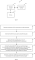
- the apparatus 40 of an example embodiment depicted in Figure 7 includes, is associated with or is otherwise in communication with processing circuitry 42, memory 44 and communication interface 46.
- the processing circuitry (and/or co-processors or any other processors assisting or otherwise associated with the processing circuitry) can be in communication with the memory via a bus for passing information among components of the apparatus.
- the memory can be non-transitory and can include, for example, one or more volatile and/or non-volatile memories.
- the memory may be an electronic storage device (for example, a computer readable storage medium) comprising gates configured to store data (for example, bits) that can be retrievable by a machine (for example, a computing device like the processing circuitry).
- the memory can be configured to store information, data, content, applications, instructions, or the like for enabling the apparatus to carry out various functions in accordance with an example embodiment of the present disclosure.
- the memory can be configured to buffer input data for processing by the processing circuitry. Additionally or alternatively, the memory can be configured to store instructions for execution by the processing circuitry.
- the processing circuitry 42 can be embodied in a number of different ways.
- the processing circuitry may be embodied as one or more of various hardware processing means such as a processor, a coprocessor, a microprocessor, a controller, a digital signal processor (DSP), a processing element with or without an accompanying DSP, or various other processing circuitry including integrated circuits such as, for example, an ASIC (application specific integrated circuit), an FPGA (field programmable gate array), a microcontroller unit (MCU), a hardware accelerator, a special-purpose computer chip, or the like.
- the processing circuitry can include one or more processing cores configured to perform independently. Additionally or alternatively, the processing circuitry can include one or more processors configured in tandem via the bus.
- the processing circuitry 42 can be configured to execute instructions stored in the memory 44 or otherwise accessible to the processing circuitry.
- the processing circuitry can be configured to execute hard coded functionality.
- the processing circuitry can represent an entity (for example, physically embodied in circuitry) capable of performing operations according to an embodiment of the present disclosure while configured accordingly.
- the processing circuitry when the processing circuitry is embodied as an ASIC, FPGA or the like, the processing circuitry can be specifically configured hardware for conducting the operations described herein.
- the processing circuitry when the processing circuitry is embodied as an executor of software instructions, the instructions can specifically configure the processing circuitry to perform the algorithms and/or operations described herein when the instructions are executed.
- the processing circuitry can be a processor of a specific device (for example, a mobile device, a server or other computing device of a positioning system or other network entity) configured to employ an embodiment of the present disclosure by further configuration of the processor by instructions for performing the algorithms and/or operations described herein.
- the processing circuitry can include, among other things, a clock, an arithmetic logic unit (ALU) and/or one or more logic gates configured to support operation of the processing circuitry.
- ALU arithmetic logic unit
- the apparatus 40 of an example embodiment can also include the communication interface 46 that can be any means such as a device or circuitry embodied in either hardware or a combination of hardware and software that is configured to receive and/or transmit data from/to other electronic devices in communication with the apparatus, such as a database which, in one embodiment, stores a radio map generated and/or employed by the processing circuitry 42.
- the communication interface may be configured to support communication, for example, between one or more mobile devices, a positioning system and/or one or more other network entities.
- the communication interface may also be configured to communicate in accordance with various wireless protocols including communication with one or more wireless communication nodes of a cellular system and/or a non-cellular system.
- the communication interface can include, for example, an antenna (or multiple antennas) and supporting hardware and/or software for enabling communications with a wireless communication network.
- the communication interface can include, for example, an antenna (or multiple antennas) and supporting hardware and/or software for enabling communications with a wireless communication network.
- the communication interface can include the circuitry for interacting with the antenna(s) to cause transmission of signals via the antenna(s) or to handle receipt of signals received via the antenna(s).
- the communication interface can alternatively or also support wired communication.
- the apparatus includes means, such as the processing circuitry 42, the communication interface 46 or the like, for determining the presence of a first access point in a radio environment.
- the first access point is an access point that is new to the radio environment or that has relocated to a new position within the radio environment.
- the presence of the first access point may be determined in various manners. In an example embodiment, however, the presence of the first access point may be determined based on one or more probe points that are associated with the first access point.
- the one or more probe points may be received, such as via the communication interface, and determined, such as by the processing circuitry, to be representative of radio signals transmitted by a respective beam of the first access point and detected by a mobile device within the radio environment.
- the probe points 38 representative of radio signals transmitted by the access point 36 designated D may identify the beamforming access point that transmitted the radio signals based upon an indication included or otherwise associated with the radio signals.
- the radio signals may be utilized to determine the presence of a new access point to the radio environment, such as based upon a comparison of the identity of the access point that transmitted the radio signals to the existing access points that were previously determined to be in the radio environment.
- the probe points may be associated with an access point that was not previously detected to be within the radio environment in the case of a new access point.
- the probe points may be detected by a mobile device to be within a portion of the radio environment that was outside of the radio model of an existing access point, such as in the case in which the access point that had been relocated within the radio environment.
- the apparatus 40 also includes means, such as the processing circuitry 42 or the like, configured to determine that the first access point is a beamforming node.
- the first access point may be determined to be a beamforming node in various manners.
- the apparatus such as the processing circuitry, may be configured to determine that the first access point is a beamforming node by detecting that the first access point employs beam sweeping to alter signal strengths of the plurality of beams transmitted by the first access point over time.
- the radio signals that are received, such as by the communication interface 46 may include an indication that the first access point is a beamforming node.
- the indication may explicitly indicate that the first access point is a beamforming node, such as by providing a flag or other indicia that the first access point is a beamforming node, or the indication may be implicit, such as by providing information regarding the number of beams transmitted by the first access point and identifying the particular beam via which the radio signals are transmitted.
- the apparatus 40 such as the processing circuitry 42, the communication interface 46 or the like, is configured to determine whether the first access point is a beamforming node by determining a measure, e.g., the received signal strength, of the signals received from first access point at each of a plurality of different points in time.
- the apparatus of this example embodiment may also include means, such as the processing circuitry, the communication interface or the like, for identifying, from the measure of the signals received from the first access point, that two or more different beams of radio signals are received, such as at different points in time, from the first access point that is identified as a beamforming node.
- the apparatus such as the processing circuitry, communication interface or the like, of this example embodiment is configured to measure the radio signals received from first access point at two or more different times and to identify, based upon the measurements at two or more different times, whether different beams of radio signals are received from the same access point, that is, the first access point.
- the apparatus such as the processing circuitry, is configured to identify the first access point as a beamforming node.
- the apparatus 40 such as the processing circuitry 42, the communication interface 46 or the like, of an example embodiment may be configured to identify that two or more beams of radio signals that are received at different times from the first access point are different in an instance in which the measures of the different beams of radio signals vary by more than a predefined amount or by more than a predefined percentage.
- the apparatus such as the processing circuitry, the communication interface or the like, of this example embodiment is configured to accommodate a small deviation in the beams of radio signals received from the first access point at different points in time without identifying the first access point as a beamforming node.
- the apparatus such as the processing circuitry, the communication interface or the like, of this example embodiment is only configured to identify the first access point as a beamforming node in an instance in which the beams of radio signals received from the first access point at different points in time are more substantially different, such as by differing by more than the predefined amount or the predefined percentage.
- the apparatus such as the processing circuitry, the communication interface or the like, may be configured such that any difference in the beams of radio signals received from the first access point at different points in time may cause the first access point to be identified as a beamforming node.
- the apparatus 40 also includes means, such as the processing circuitry 42, the communication interface 46 or the like, configured to obtain information regarding one or more of a plurality of beams of which the one or more probe points are representative.
- the information regarding one or more of the plurality of beams such as the beam via which the radio signals are transmitted, may include information identifying the respective beam and the total number of beams transmitted by the first access point.
- the information regarding the one or more of the plurality of beams may include the signal propagation characteristics of the first access point.
- the signal propagation characteristics may include the presence (or absence) of signals transmitted by a respective access point that have at least a predefined signal strength at one or more locations.
- the signal propagation characteristics may include the signal strength of the signals transmitted by the respective beam of the beamforming access point at one or more locations.
- the information that is obtained may relate to additional or different signal propagation characteristics, at least some of which are associated with one or more locations within the radio environment.
- the apparatus 40 also includes means, such as the processing circuitry 42 or the like, configured to estimate the radio model of the first access point 36 based at least upon: (i) at least some of the information regarding the one or more of the beams transmitted by the first access point and (ii) signal propagation characteristics of one or more existing access points in the radio environment as represented by respective radio models of the one or more existing access points.
- the information regarding a beam transmitted by the first access point may include information identifying the beam and, in some embodiments, the total number of beams transmitted by the first access point.
- the information may also include signal propagation characteristics of the first access point, such as the presence (or absence) of signals transmitted by the respective beam of the first access point that have at least a predefined signal strength at one or more locations and/or the signal strength of the signals transmitted by the respective beam of the first access point at one or more locations.
- signal propagation characteristics of the first access point such as the presence (or absence) of signals transmitted by the respective beam of the first access point that have at least a predefined signal strength at one or more locations and/or the signal strength of the signals transmitted by the respective beam of the first access point at one or more locations.
- the signal propagation characteristics of the one or more existing access points 30 may be represented by respective radio models 32 which define the presence (or absence) of signals transmitted by respective beams of the existing access points that have at least a predefined signal strength at one or more locations and/or the signal strength of the signals transmitted by the respective beams of the existing access points at one or more locations.
- the radio model 38 of the new beamforming access point 36 designated D may be estimated based upon the signal propagation characteristics of the existing access points designated A, B and C within the radio environment, such as depicted in Figure 9 .
- the radio model 39 of the new beamforming access point of Figure 9 is much more comparable to the radio models of the existing access points in the same radio environment than the radio model that would otherwise be constructed based upon a limited number of initial probe points 38, such as described above and shown in Figure 6 .
- the radio model that is estimated for the new beamforming access point in accordance with an example embodiment can more accurately represent the signal propagation characteristics of the radio signals transmitted by the new access point.
- the radio model of the new beamforming access point may be estimated in accordance with an example embodiment relatively soon after having determined the presence of the new access point without awaiting the collection of a more substantial number of probe points from the new access point.
- the apparatus 40 may be configured to estimate the radio model of the first access point 36 in various manners.
- the estimation of the radio model of the first access point includes orienting the radio model of the first access point, such as by orienting the beam that transmits the radio signals that have been received, such as a first probe point, relative to the other beams of the first access point.
- the radio model may be oriented in various manners, but, in one embodiment, the apparatus, such as the processing circuitry, is configured to orient the radio model based at least in part upon the identification of the respective beam of the first access point in relation to the total number of beams of the first access point.
- the apparatus 40 is additionally or alternatively configured to estimate the radio model 39 of the first access point 36 based upon the size and/or the shape of the respective radio models 32 of the existing access points 30.
- the apparatus such as the processing circuitry, is configured to estimate the size of the radio model of the beams of the first access point to be the same or to be approximately equal to the size of the corresponding beams of the radio models of the existing access points.
- the apparatus such as the processing circuitry, is configured to estimate the shape of the radio model of the beams of the first access point to have the same or a similar shape as the shape of the radio models of the beams of the existing access points.
- the relative size and shape of the radio model of the beams of the first access point may be the same as or may correspond to the size and shape of the radio models of the existing access points, such as the size and shape of the radio models of the beams of the existing access points in an instance in which the existing access points are also beamforming.
- the apparatus 40 may also include means, such as the processing circuitry 42 or the like, configured to determine the presence of the obstacle 34 and/or characteristics of the obstacle, such as the location, size and/or shape of the obstacle, based on signal propagation characteristics of respective radio models 32 of the one or more existing access points 30.
- the apparatus, such as the processing circuitry, of this example embodiment is configured to estimate the radio model 39 of the first access point 36 based upon signal propagation characteristics of one or more existing access points by estimating the radio model of the first access point based on the determined presence of the obstacle and/or characteristics of the obstacle.
- the radio model of each of the existing access points may be considered equally in relation to the estimation of the radio model 39 of the first access point 36 that is newly present or newly located within the radio environment.
- the apparatus 40 includes means, such as the processing circuitry 42 or the like, configured to differently weight the contributions of the respective radio models of the one or more existing access points to the estimation of the radio model of the first access point based upon one or more weighting factors.
- the weighting factors are based on whether the existing access points are beamforming access points or static access points that have a constant radio model that does not materially change over time.
- an existing access point may be weighted more greatly in an instance in which the existing access point is a beamforming access point, like the first access point.
- an existing access point may be weighted more lightly in an instance in which the existing access point is a static access point having a constant radio model.
- the radio model of an existing beamforming access point will have a greater contribution to the estimation of the radio model of the first access point than the radio model of an existing static access point that has a constant radio model.
- the weighting factors additionally or alternatively include the confidence associated with the radio models 32 of the existing access points 30.
- the contribution of a respective radio model of an existing access point to the estimation of the radio model 39 of the first access point 36 may be weighted in a manner that has a direct relationship, such as a proportional relationship, to the confidence associated with the respective radio model of existing access point.
- the confidence associated with the radio models of the existing access points may be based upon the number of probe points that have been collected for the existing access points which, in turn, is evidence of the relative reliability of the radio models.
- a weighting factor of this example embodiment includes the number of probe points that have been collected for respective ones of the existing access points.
- the contribution of a respective radio model of an existing access point to the estimation of the radio model of the first access point may be weighted in a manner that has a direct relationship, such as a proportional relationship, to the number of probe points that have been collected for the respective existing access point.
- the contribution of the respective radio model of an existing access point is weighted more heavily in an instance in which a large number of probe points have been collected for the respective access point than in an instance in which only a few number of probe points have been collected for the existing access point.
- the radio model of an existing access point for which a large number of probe points have been collected will therefore have a greater contribution to the estimation of the radio model of the first access point than the radio model of an existing access point for which only a few probe points have been collected.
- the confidence associated with the radio models 32 of the existing access points 30 may additionally or alternatively be based upon the freshness of the radio models as defined, for example, by the time elapsed since the probe points have been collected for respective ones of the existing access points.
- another weighting factor that may be considered in addition to, or instead of, the number of probe points have been collected for respective ones of the existing access points is the time elapsed since the probe points have been collected for respective ones of the existing access points.
- the contribution of a respective radio model of an existing access point to the estimation of the radio model 39 of the first access point 36 may be weighted in a manner that has an indirect relationship, such as an inversely proportional relationship, to the time elapsed since the probe points have been collected for respective ones of the existing access points.
- the contribution of the respective radio model of an existing access point is weighted more heavily in an instance in which at least some of the probe points have been recently collected such that the time elapsed since the most recent probe points have been collected is relatively small than in an instance in which no probe points have been collected for a longer period of time such that the time elapsed since the most recent probe points have been collected is relatively large.
- the radio model of an existing access point for which probe points have been collected more recently will therefore have a greater contribution to the estimation of the radio model of the first access point than the radio model of an existing access point for which no probe points have been collected for a longer period of time.
- the degree of similarity is a measure of the similarity between the shapes and sizes of the respective radio models of the existing access points.
- the contribution of a respective radio model of an existing access point to the estimation of the radio model 39 of the first access point 36 may be weighted in a manner that has an direct relationship, such as a proportional relationship, to the similarity that the respective radio model of the existing access point has to the respective radio models of one or more other existing access points.
- the contribution of the respective radio model of an existing access point is weighted more heavily in an instance in which the respective radio model of the existing access point is similar in size and/or shape to the respective radio model(s) of one or more other existing access points than in an instance in which the respective radio model of the existing access point is dissimilar in both size and shape to the respective radio model(s) of all of the other existing access points.
- the radio model of an existing access point that is similar in size and/or shape to the respective radio model(s) of one or more other existing access points will therefore have a greater contribution to the estimation of the radio model of the first access point than the radio model of an existing access point that is dissimilar in size and shape to the radio models of all of the other existing access points.
- the weighting may be further dependent upon the number of radio models 32 of the existing access points 30 that are similar in size and/or shape and/or the degree of similarity between the radio models of the existing access points.
- the weighting may have a direct relationship, such as a proportional relationship, to the number of radio models of the existing access points that are similar in size and/or shape.
- the weighting may have a direct relationship, such as a proportional relationship, to the degree of similarity between the radio models of the existing access points.
- the apparatus 40 such as the processing circuitry 42, is configured to weight the contributions of the respective radio models of the one or more existing access points to the estimation of the radio model of the first access point based upon the information regarding respective positions of the first access point and then one or more existing access points as well as information regarding the position and orientation of the obstacle to signal propagation within the environment.
- the apparatus 40 optionally includes means, such as the processing circuitry 42 or the like, configured to determine the location of the mobile device at least partially based upon an estimation of the radio model of the first access point. See block 58 of Figure 8 .
- the apparatus such as the processing circuitry, may also be configured in some, but not all embodiments, to determine the location of the mobile device based upon the respective radio models of the one or more existing access points in addition to the estimation of the radio model of the first access point.
- the apparatus 40 of this example embodiment includes means, such as the processing circuitry 42, the communication interface 46 or the like, configured to receive one or more probe points for the first access point following estimation of the radio model of the first access point.
- these probe points may be representative of information collected by a mobile device within the radio environment based upon radio signals transmitted by the first access point and received by the mobile device, including, for example, an indication of the beam of the first access point that has transmitted the radio signals.
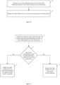
- the apparatus 40 of this example embodiment also includes means, such as the processing circuitry 42 or the like, configured to determine whether to update the radio model 39 of the first access point 36 based upon an updated version of the respective radio model 32 of at least one of the one or more existing access points 30.
- the apparatus such as the processing circuitry, is configured to determine whether to update the radio model of the first access point based upon the number of probe points that have been collected for the first access point. In this regard, in an instance in which fewer probe points have been collected for the first access point, the apparatus, such as the processing circuitry, will be more likely to update the radio model of first access point based upon updates to the radio model of an existing access point. Conversely, in an instance in which a larger number of probe points have been collected for the first access point, the apparatus, such as the processing circuitry, will be less likely to update the radio model of first access point based upon updates to the radio model of an existing access point.
- the apparatus such as the processing circuitry, of this example embodiment is configured to update the radio model of the first access point based upon the respective radio model, as updated, of an existing access point. See block 66 of Figure 11 . Consequently, the accuracy of the radio model of the first access point may be enhanced based upon an update to the radio model of an existing access point in an instance in which only a few probe points have been collected for the first access point, such as less than the predetermined number of probe points.
- a method, apparatus 40 and computer program product are provided in order to accelerate the estimation of the radio model 39 of a beamforming access point 36 within a radio environment, such as a beamforming access point that has been newly added to the radio environment or a beamforming access point that is been moved or relocated within the radio environment.
- the radio model that is estimated in accordance with an example embodiment may not only be more quickly defined, but may be defined with enhanced accuracy relative to radio models that are defined on the basis of only a few probe points 38.
- the radio model that is estimated by the method, apparatus and computer program product of an example embodiment may be utilized to reliably determine the position of a mobile terminal within the radio environment.
- FIGS 8 , 10 and 11 illustrate flowcharts depicting methods according to an example embodiment of the present invention. It will be understood that each block of the flowcharts and combination of blocks in the flowcharts may be implemented by various means, such as hardware, firmware, processor, circuitry, and/or other communication devices associated with execution of software including one or more computer program instructions. For example, one or more of the procedures described above may be embodied by computer program instructions. In this regard, the computer program instructions which embody the procedures described above may be stored by a memory 24 of an apparatus 40 employing an embodiment of the present invention and executed by the processing circuitry 42.
- any such computer program instructions may be loaded onto a computer or other programmable apparatus (for example, hardware) to produce a machine, such that the resulting computer or other programmable apparatus implements the functions specified in the flowchart blocks.
- These computer program instructions may also be stored in a computer-readable memory that may direct a computer or other programmable apparatus to function in a particular manner, such that the instructions stored in the computer-readable memory produce an article of manufacture the execution of which implements the function specified in the flowchart blocks.
- the computer program instructions may also be loaded onto a computer or other programmable apparatus to cause a series of operations to be performed on the computer or other programmable apparatus to produce a computer-implemented process such that the instructions which execute on the computer or other programmable apparatus provide operations for implementing the functions specified in the flowchart blocks.
- blocks of the flowcharts support combinations of means for performing the specified functions and combinations of operations for performing the specified functions for performing the specified functions. It will also be understood that one or more blocks of the flowcharts, and combinations of blocks in the flowcharts, can be implemented by special purpose hardware-based computer systems which perform the specified functions, or combinations of special purpose hardware and computer instructions.
Landscapes
- Engineering & Computer Science (AREA)
- Computer Networks & Wireless Communication (AREA)
- Signal Processing (AREA)
- Physics & Mathematics (AREA)
- Electromagnetism (AREA)
- Quality & Reliability (AREA)
- Spectroscopy & Molecular Physics (AREA)
- Mobile Radio Communication Systems (AREA)
Claims (10)
- Verfahren zur Beschleunigung der Schätzung eines Funkmodells (32) eines ersten Zugangspunktes (20), wobei das Funkmodell (32) einem Bereich entspricht, in dem von dem ersten Zugangspunkt (20) gesendete Funksignale mit mindestens einer vordefinierten Signalstärke detektierbar sind, wobei das Verfahren umfasst:Bestimmen des Vorhandenseins des ersten Zugangspunkts (20) in einer Funkumgebung;Bestimmen, dass der erste Zugangspunkt (20) ein Strahlungsformungsknoten ist, und Erhalten von Informationen bezüglich eines oder mehrerer einer Vielzahl von Strahlen (22), wobei die Vielzahl von Strahlen (22) von dem ersten Zugangspunkt (20) übertragen wird; undSchätzen des Funkmodells (32) des ersten Zugangspunkts auf der Grundlage von mindestens: (i) mindestens einigen der Informationen bezüglich des einen oder der mehreren von dem ersten Zugangspunkt (20) übertragenen Strahlen (22) und (ii) Signalausbreitungscharakteristiken eines oder mehrerer bestehender Zugangspunkte (30) in der Funkumgebung, wie sie durch jeweilige Funkmodelle (32) des einen oder der mehreren bestehenden Zugangspunkte (30) repräsentiert werden.
- Verfahren nach Anspruch 1, wobei das Bestimmen des Vorhandenseins des ersten Zugangspunkts (20) das Bestimmen des Vorhandenseins des ersten Zugangspunkts (20) auf der Grundlage mindestens eines ersten Messpunkts (38) umfasst, der für Funksignale repräsentativ ist, die von einem jeweiligen Strahl aus der von dem ersten Zugangspunkt (22) übertragen Vielzahl von Strahlen (22) übertragen werden, und wobei das Erhalten von Informationen bezüglich eines oder mehrerer der von dem ersten Zugangspunkt (20) übertragenen Vielzahl von Strahlen (22) das Erhalten von Informationen bezüglich einer Gesamtzahl von Strahlen (22) und einer Identifikation des jeweiligen Strahls des ersten Zugangspunkts (20) umfasst, der die Funksignale bereitstellt, für die der erste Messpunkt (38) repräsentativ ist.
- Verfahren nach Anspruch 2, wobei das Schätzen des Funkmodells (32) des ersten Zugangspunkts (20) das Ausrichten des Funkmodells (32) des ersten Zugangspunkts (20) zumindest teilweise auf der Grundlage der Identifikation des jeweiligen Strahls des ersten Zugangspunkts (20) in Bezug auf die Gesamtzahl der Strahlen (22) des ersten Zugangspunkts (20) umfasst.
- Verfahren nach einem der Ansprüche 2 und 3, ferner umfassend das Empfangen von Informationen bezüglich eines zweiten Messpunkts (38), der für Funksignale repräsentativ ist, die von einem anderen Strahl der von dem ersten Zugangspunkt (20) übertragenen Vielzahl von Strahlen (22) übertragen werden, und wobei das Schätzen des Funkmodells (32) des ersten Zugangspunkts (20) das Ausrichten des Funkmodells (32) des ersten Zugangspunkts (20) zumindest teilweise auf der Grundlage der relativen Positionen des jeweiligen Strahls und des anderen Strahls in Bezug auf die Gesamtzahl von Strahlen (22) des ersten Zugangspunkts (20) umfasst.
- Verfahren nach einem der Ansprüche 2 bis 4, ferner umfassend das Empfangen von Informationen bezüglich eines zweiten Messpunkts (38), der für die in dem jeweiligen Strahl des ersten Zugangspunkts (20) übertragenen Funksignale repräsentativ ist, wobei der erste und der zweite Messpunkt (38) jeweils mit unterschiedlichen Orten assoziiert sind und Informationen bezüglich einer Signalstärke der in dem jeweiligen Strahl des ersten Zugangspunkts (20) übertragenen und an dem jeweiligen Ort empfangenen Funksignale bereitstellen, und wobei das Schätzen des Funkmodells (32) des ersten Zugangspunkts (20) das Schätzen des Funkmodells (32) des ersten Zugangspunkts (20) das Schätzen des Funkmodells (32) des ersten Zugangspunkts (20) zumindest teilweise auf der Grundlage der Signalstärke der Funksignale, die durch den ersten Messpunkt (38) repräsentiert werden, und der Signalstärke der Funksignale, die durch den zweiten Messpunkt (38) repräsentiert werden, umfasst.
- Verfahren nach einem der Ansprüche 1 bis 5, wobei das Schätzen des Funkmodells (32) des ersten Zugangspunkts (20) das Schätzen des Funkmodells (32) des ersten Zugangspunkts (20) auf der Grundlage mindestens einer Größe oder Form der jeweiligen Funkmodelle (32) des einen oder der mehreren vorhandenen Zugangspunkte (30) umfasst.
- Verfahren nach einem der Ansprüche 1 bis 6, wobei das Schätzen des Funkmodells (32) des ersten Zugangspunkts (20) das Schätzen des Funkmodells (32) des ersten Zugangspunkts (20) auf der Grundlage mindestens einer Form der jeweiligen Funkmodelle (32) des einen oder der mehreren vorhandenen Zugangspunkte (30) relativ zu einem Hindernis (34) innerhalb der Funkumgebung umfasst, wobei das Hindernis (34) ein Hindernis (34) für die Signalausbreitung innerhalb der Funkumgebung umfasst.
- Verfahren nach einem der Ansprüche 1 bis 7, wobei das Bestimmen, dass der erste Zugangspunkt (20) ein Strahlformungsknoten ist, das Detektieren umfasst, dass der erste Zugangspunkt (20) die Strahlschwenkung verwendet, um die Signalstärken der Vielzahl von Strahlen (22), die von dem ersten Zugangspunkt (20) übertragen werden, über die Zeit zu ändern.
- Vorrichtung umfassend Mittel, die zur Durchführung des Verfahrens nach einem der Ansprüche 1 bis 8 konfiguriert sind.
- Vorrichtung nach Anspruch 9, wobei die Mittel eine Verarbeitungsschaltung und mindestens einen Speicher mit Computerprogrammcode-Anweisungen umfassen, wobei die Computerprogrammcode-Anweisungen konfiguriert, um, wenn sie von der Verarbeitungsschaltung ausgeführt werden, die Vorrichtung zu veranlassen, das Verfahren nach einem der Ansprüche 1 bis 8 durchzuführen.
Applications Claiming Priority (1)
| Application Number | Priority Date | Filing Date | Title |
|---|---|---|---|
| US17/316,840 US11916630B2 (en) | 2021-05-11 | 2021-05-11 | Method and apparatus for accelerating estimation of a radio model of a beamforming access point |
Publications (2)
| Publication Number | Publication Date |
|---|---|
| EP4089933A1 EP4089933A1 (de) | 2022-11-16 |
| EP4089933B1 true EP4089933B1 (de) | 2025-04-16 |
Family
ID=82058478
Family Applications (1)
| Application Number | Title | Priority Date | Filing Date |
|---|---|---|---|
| EP22172691.2A Active EP4089933B1 (de) | 2021-05-11 | 2022-05-11 | Verfahren und vorrichtung zur beschleunigten schätzung eines funkmodells eines strahlformungszugriffspunktes |
Country Status (2)
| Country | Link |
|---|---|
| US (1) | US11916630B2 (de) |
| EP (1) | EP4089933B1 (de) |
Family Cites Families (13)
| Publication number | Priority date | Publication date | Assignee | Title |
|---|---|---|---|---|
| US7583961B2 (en) * | 2004-04-28 | 2009-09-01 | Avaya Inc. | Method and apparatus for generating a signal strength model for an access point at an arbitrary location |
| US8000276B2 (en) | 2007-02-05 | 2011-08-16 | Wefi, Inc. | Providing easy access to radio networks |
| WO2009144030A2 (en) | 2008-05-30 | 2009-12-03 | Siemens Aktiengesellschaft | Method for generating a radio map of an environment and radio communication system being controlled on the basis of a radio map generated by this method |
| US10136262B2 (en) * | 2014-04-28 | 2018-11-20 | Hewlett Packard Enterprise Development Lp | Detecting movement in a physical environment |
| EP3227706B1 (de) * | 2014-12-04 | 2023-02-15 | HERE Global B.V. | Unterstützung der qualitätssicherung eines funkmodells |
| US10390174B2 (en) | 2015-09-03 | 2019-08-20 | Extreme Networks, Inc. | Methods and systems for mitigating the impact of beamforming on the accuracy of Wi-Fi based location tracking of client devices |
| WO2017184190A1 (en) | 2016-04-18 | 2017-10-26 | Intel Corporation | Selection of beamforming directions based on learned performance |
| GB2551476A (en) * | 2016-05-11 | 2017-12-27 | Nokia Solutions & Networks Oy | Method, system and apparatus |
| US10840982B2 (en) | 2016-08-11 | 2020-11-17 | Convidia Wireless, LLC | Beamforming sweeping and training in a flexible frame structure for new radio |
| US11243983B2 (en) | 2017-10-30 | 2022-02-08 | Qualcomm Incorporated | System and method for compact storage and efficient retrieval of access point information for detecting rogue access points |
| CN110418285A (zh) | 2018-04-26 | 2019-11-05 | 中移(苏州)软件技术有限公司 | 一种无线电地图的建立方法及装置 |
| US10827451B2 (en) * | 2018-06-30 | 2020-11-03 | Silicon Laboratories Inc. | Method and system of locating a wireless device using received signal strengths |
| EP3997927B1 (de) | 2019-07-09 | 2025-10-15 | Telefonaktiebolaget LM Ericsson (publ.) | Unterscheidung von strahlen basierend auf einer positionsgütemetrik zur lokalisierung von benutzergeräten |
-
2021
- 2021-05-11 US US17/316,840 patent/US11916630B2/en active Active
-
2022
- 2022-05-11 EP EP22172691.2A patent/EP4089933B1/de active Active
Also Published As
| Publication number | Publication date |
|---|---|
| US11916630B2 (en) | 2024-02-27 |
| EP4089933A1 (de) | 2022-11-16 |
| US20220368392A1 (en) | 2022-11-17 |
Similar Documents
| Publication | Publication Date | Title |
|---|---|---|
| Rezazadeh et al. | Novel iBeacon placement for indoor positioning in IoT | |
| CN108040318B (zh) | 一种定位方法、电子设备及计算机可读存储介质 | |
| CN101304609B (zh) | 用于检测网络中终端位置的系统和方法 | |
| US8378891B2 (en) | Method and system for optimizing quality and integrity of location database elements | |
| CN113518301B (zh) | 一种定位参考信号配置方法、lmf、终端及基站 | |
| Lee et al. | Method for improving indoor positioning accuracy using extended Kalman filter | |
| CN111352069B (zh) | 一种室内定位方法、服务器、存储介质及程序产品 | |
| US10009733B2 (en) | Method and system for determining a position of a mobile device by an access point | |
| KR20050121176A (ko) | 순차 송수신 방식을 이용한 비동기 무선 측위 시스템 및방법 | |
| US10444319B2 (en) | Determining of model parameters for positioning purposes | |
| US11310339B2 (en) | Selecting a positioning technique based on the accuracy | |
| CN107431995A (zh) | 实现对移动装置的估计位置的验证 | |
| CN106028280A (zh) | 一种定位方法、装置和儿童手表 | |
| US11803580B2 (en) | Apparatus and method for machine-learning-based positioning database creation and positioning of uncollected points using matching feature with wireless communication infrastructure | |
| CN103220780A (zh) | 室内定位方法、装置及系统 | |
| EP3929611A1 (de) | Verfahren und vorrichtung zur führung der probendatensammlung | |
| CN104125636B (zh) | 一种基站定位方法及装置 | |
| EP4089933B1 (de) | Verfahren und vorrichtung zur beschleunigten schätzung eines funkmodells eines strahlformungszugriffspunktes | |
| JP6640309B1 (ja) | 位置推定装置、プログラム、位置推定方法、情報処理装置、及び情報処理方法 | |
| CN105393611B (zh) | 一种定位用户设备的方法、设备和系统 | |
| KR102765428B1 (ko) | 패킷 캡쳐 기반 실내 위치 추정 장치 및 방법 | |
| EP3205159A1 (de) | Positionsanpassung in mobilkommunikationsnetzwerken | |
| US11546779B2 (en) | Method and apparatus for accelerating estimation of a radio model of an access point | |
| EP2887748B1 (de) | Verfahren zur bestimmung der positionen mobiler empfängereinheiten in geschlossenen räumen | |
| EP3930390B1 (de) | Verfahren und vorrichtung zur einschränkung der verwendung eines strahlformungsknotens zu positionierungszwecken |
Legal Events
| Date | Code | Title | Description |
|---|---|---|---|
| PUAI | Public reference made under article 153(3) epc to a published international application that has entered the european phase |
Free format text: ORIGINAL CODE: 0009012 |
|
| STAA | Information on the status of an ep patent application or granted ep patent |
Free format text: STATUS: THE APPLICATION HAS BEEN PUBLISHED |
|
| AK | Designated contracting states |
Kind code of ref document: A1 Designated state(s): AL AT BE BG CH CY CZ DE DK EE ES FI FR GB GR HR HU IE IS IT LI LT LU LV MC MK MT NL NO PL PT RO RS SE SI SK SM TR |
|
| STAA | Information on the status of an ep patent application or granted ep patent |
Free format text: STATUS: REQUEST FOR EXAMINATION WAS MADE |
|
| 17P | Request for examination filed |
Effective date: 20230426 |
|
| RBV | Designated contracting states (corrected) |
Designated state(s): AL AT BE BG CH CY CZ DE DK EE ES FI FR GB GR HR HU IE IS IT LI LT LU LV MC MK MT NL NO PL PT RO RS SE SI SK SM TR |
|
| STAA | Information on the status of an ep patent application or granted ep patent |
Free format text: STATUS: EXAMINATION IS IN PROGRESS |
|
| 17Q | First examination report despatched |
Effective date: 20240416 |
|
| GRAP | Despatch of communication of intention to grant a patent |
Free format text: ORIGINAL CODE: EPIDOSNIGR1 |
|
| STAA | Information on the status of an ep patent application or granted ep patent |
Free format text: STATUS: GRANT OF PATENT IS INTENDED |
|
| RIC1 | Information provided on ipc code assigned before grant |
Ipc: H04W 64/00 20090101ALN20241011BHEP Ipc: H04B 7/06 20060101ALN20241011BHEP Ipc: H04B 17/391 20150101ALI20241011BHEP Ipc: H04B 17/27 20150101AFI20241011BHEP |
|
| INTG | Intention to grant announced |
Effective date: 20241112 |
|
| RIC1 | Information provided on ipc code assigned before grant |
Ipc: H04W 64/00 20090101ALN20241106BHEP Ipc: H04B 7/06 20060101ALN20241106BHEP Ipc: H04B 17/391 20150101ALI20241106BHEP Ipc: H04B 17/27 20150101AFI20241106BHEP |
|
| GRAS | Grant fee paid |
Free format text: ORIGINAL CODE: EPIDOSNIGR3 |
|
| GRAA | (expected) grant |
Free format text: ORIGINAL CODE: 0009210 |
|
| STAA | Information on the status of an ep patent application or granted ep patent |
Free format text: STATUS: THE PATENT HAS BEEN GRANTED |
|
| AK | Designated contracting states |
Kind code of ref document: B1 Designated state(s): AL AT BE BG CH CY CZ DE DK EE ES FI FR GB GR HR HU IE IS IT LI LT LU LV MC MK MT NL NO PL PT RO RS SE SI SK SM TR |
|
| REG | Reference to a national code |
Ref country code: GB Ref legal event code: FG4D |
|
| REG | Reference to a national code |
Ref country code: CH Ref legal event code: EP |
|
| REG | Reference to a national code |
Ref country code: IE Ref legal event code: FG4D |
|
| REG | Reference to a national code |
Ref country code: DE Ref legal event code: R096 Ref document number: 602022013111 Country of ref document: DE |
|
| REG | Reference to a national code |
Ref country code: NL Ref legal event code: FP |
|
| PGFP | Annual fee paid to national office [announced via postgrant information from national office to epo] |
Ref country code: DE Payment date: 20250408 Year of fee payment: 4 |
|
| PGFP | Annual fee paid to national office [announced via postgrant information from national office to epo] |
Ref country code: AT Payment date: 20250721 Year of fee payment: 4 |
|
| REG | Reference to a national code |
Ref country code: AT Ref legal event code: MK05 Ref document number: 1786539 Country of ref document: AT Kind code of ref document: T Effective date: 20250416 |
|
| PG25 | Lapsed in a contracting state [announced via postgrant information from national office to epo] |
Ref country code: FI Free format text: LAPSE BECAUSE OF FAILURE TO SUBMIT A TRANSLATION OF THE DESCRIPTION OR TO PAY THE FEE WITHIN THE PRESCRIBED TIME-LIMIT Effective date: 20250416 Ref country code: PT Free format text: LAPSE BECAUSE OF FAILURE TO SUBMIT A TRANSLATION OF THE DESCRIPTION OR TO PAY THE FEE WITHIN THE PRESCRIBED TIME-LIMIT Effective date: 20250818 Ref country code: ES Free format text: LAPSE BECAUSE OF FAILURE TO SUBMIT A TRANSLATION OF THE DESCRIPTION OR TO PAY THE FEE WITHIN THE PRESCRIBED TIME-LIMIT Effective date: 20250416 |
|
| REG | Reference to a national code |
Ref country code: LT Ref legal event code: MG9D |
|
| PG25 | Lapsed in a contracting state [announced via postgrant information from national office to epo] |
Ref country code: NO Free format text: LAPSE BECAUSE OF FAILURE TO SUBMIT A TRANSLATION OF THE DESCRIPTION OR TO PAY THE FEE WITHIN THE PRESCRIBED TIME-LIMIT Effective date: 20250716 Ref country code: GR Free format text: LAPSE BECAUSE OF FAILURE TO SUBMIT A TRANSLATION OF THE DESCRIPTION OR TO PAY THE FEE WITHIN THE PRESCRIBED TIME-LIMIT Effective date: 20250717 |
|
| PG25 | Lapsed in a contracting state [announced via postgrant information from national office to epo] |
Ref country code: PL Free format text: LAPSE BECAUSE OF FAILURE TO SUBMIT A TRANSLATION OF THE DESCRIPTION OR TO PAY THE FEE WITHIN THE PRESCRIBED TIME-LIMIT Effective date: 20250416 |
|
| PG25 | Lapsed in a contracting state [announced via postgrant information from national office to epo] |
Ref country code: BG Free format text: LAPSE BECAUSE OF FAILURE TO SUBMIT A TRANSLATION OF THE DESCRIPTION OR TO PAY THE FEE WITHIN THE PRESCRIBED TIME-LIMIT Effective date: 20250416 |
|
| PG25 | Lapsed in a contracting state [announced via postgrant information from national office to epo] |
Ref country code: HR Free format text: LAPSE BECAUSE OF FAILURE TO SUBMIT A TRANSLATION OF THE DESCRIPTION OR TO PAY THE FEE WITHIN THE PRESCRIBED TIME-LIMIT Effective date: 20250416 Ref country code: AT Free format text: LAPSE BECAUSE OF FAILURE TO SUBMIT A TRANSLATION OF THE DESCRIPTION OR TO PAY THE FEE WITHIN THE PRESCRIBED TIME-LIMIT Effective date: 20250416 |
|
| PG25 | Lapsed in a contracting state [announced via postgrant information from national office to epo] |
Ref country code: RS Free format text: LAPSE BECAUSE OF FAILURE TO SUBMIT A TRANSLATION OF THE DESCRIPTION OR TO PAY THE FEE WITHIN THE PRESCRIBED TIME-LIMIT Effective date: 20250716 |
|
| PG25 | Lapsed in a contracting state [announced via postgrant information from national office to epo] |
Ref country code: IS Free format text: LAPSE BECAUSE OF FAILURE TO SUBMIT A TRANSLATION OF THE DESCRIPTION OR TO PAY THE FEE WITHIN THE PRESCRIBED TIME-LIMIT Effective date: 20250816 |
|
| PG25 | Lapsed in a contracting state [announced via postgrant information from national office to epo] |
Ref country code: LV Free format text: LAPSE BECAUSE OF FAILURE TO SUBMIT A TRANSLATION OF THE DESCRIPTION OR TO PAY THE FEE WITHIN THE PRESCRIBED TIME-LIMIT Effective date: 20250416 |
|
| REG | Reference to a national code |
Ref country code: CH Ref legal event code: H13 Free format text: ST27 STATUS EVENT CODE: U-0-0-H10-H13 (AS PROVIDED BY THE NATIONAL OFFICE) Effective date: 20251223 |
|
| PG25 | Lapsed in a contracting state [announced via postgrant information from national office to epo] |
Ref country code: SM Free format text: LAPSE BECAUSE OF FAILURE TO SUBMIT A TRANSLATION OF THE DESCRIPTION OR TO PAY THE FEE WITHIN THE PRESCRIBED TIME-LIMIT Effective date: 20250416 Ref country code: DK Free format text: LAPSE BECAUSE OF FAILURE TO SUBMIT A TRANSLATION OF THE DESCRIPTION OR TO PAY THE FEE WITHIN THE PRESCRIBED TIME-LIMIT Effective date: 20250416 |
|
| PG25 | Lapsed in a contracting state [announced via postgrant information from national office to epo] |
Ref country code: LU Free format text: LAPSE BECAUSE OF NON-PAYMENT OF DUE FEES Effective date: 20250511 |
|
| PG25 | Lapsed in a contracting state [announced via postgrant information from national office to epo] |
Ref country code: CH Free format text: LAPSE BECAUSE OF NON-PAYMENT OF DUE FEES Effective date: 20250531 |
|
| REG | Reference to a national code |
Ref country code: DE Ref legal event code: R097 Ref document number: 602022013111 Country of ref document: DE |
|
| PG25 | Lapsed in a contracting state [announced via postgrant information from national office to epo] |
Ref country code: CZ Free format text: LAPSE BECAUSE OF FAILURE TO SUBMIT A TRANSLATION OF THE DESCRIPTION OR TO PAY THE FEE WITHIN THE PRESCRIBED TIME-LIMIT Effective date: 20250416 |
|
| PG25 | Lapsed in a contracting state [announced via postgrant information from national office to epo] |
Ref country code: EE Free format text: LAPSE BECAUSE OF FAILURE TO SUBMIT A TRANSLATION OF THE DESCRIPTION OR TO PAY THE FEE WITHIN THE PRESCRIBED TIME-LIMIT Effective date: 20250416 |
|
| PG25 | Lapsed in a contracting state [announced via postgrant information from national office to epo] |
Ref country code: SK Free format text: LAPSE BECAUSE OF FAILURE TO SUBMIT A TRANSLATION OF THE DESCRIPTION OR TO PAY THE FEE WITHIN THE PRESCRIBED TIME-LIMIT Effective date: 20250416 |
|
| PG25 | Lapsed in a contracting state [announced via postgrant information from national office to epo] |
Ref country code: IT Free format text: LAPSE BECAUSE OF FAILURE TO SUBMIT A TRANSLATION OF THE DESCRIPTION OR TO PAY THE FEE WITHIN THE PRESCRIBED TIME-LIMIT Effective date: 20250416 |
|
| REG | Reference to a national code |
Ref country code: BE Ref legal event code: MM Effective date: 20250531 |
|
| PG25 | Lapsed in a contracting state [announced via postgrant information from national office to epo] |
Ref country code: MC Free format text: LAPSE BECAUSE OF FAILURE TO SUBMIT A TRANSLATION OF THE DESCRIPTION OR TO PAY THE FEE WITHIN THE PRESCRIBED TIME-LIMIT Effective date: 20250416 |
|
| PG25 | Lapsed in a contracting state [announced via postgrant information from national office to epo] |
Ref country code: RO Free format text: LAPSE BECAUSE OF FAILURE TO SUBMIT A TRANSLATION OF THE DESCRIPTION OR TO PAY THE FEE WITHIN THE PRESCRIBED TIME-LIMIT Effective date: 20250416 |
|
| PLBE | No opposition filed within time limit |
Free format text: ORIGINAL CODE: 0009261 |
|
| STAA | Information on the status of an ep patent application or granted ep patent |
Free format text: STATUS: NO OPPOSITION FILED WITHIN TIME LIMIT |
|
| REG | Reference to a national code |
Ref country code: CH Ref legal event code: L10 Free format text: ST27 STATUS EVENT CODE: U-0-0-L10-L00 (AS PROVIDED BY THE NATIONAL OFFICE) Effective date: 20260225 |
|
| 26N | No opposition filed |
Effective date: 20260119 |
|
| PG25 | Lapsed in a contracting state [announced via postgrant information from national office to epo] |
Ref country code: IE Free format text: LAPSE BECAUSE OF NON-PAYMENT OF DUE FEES Effective date: 20250511 |
|
| PG25 | Lapsed in a contracting state [announced via postgrant information from national office to epo] |
Ref country code: BE Free format text: LAPSE BECAUSE OF NON-PAYMENT OF DUE FEES Effective date: 20250531 |
|
| PGFP | Annual fee paid to national office [announced via postgrant information from national office to epo] |
Ref country code: NL Payment date: 20260317 Year of fee payment: 5 |
|
| PGFP | Annual fee paid to national office [announced via postgrant information from national office to epo] |
Ref country code: FR Payment date: 20260309 Year of fee payment: 5 |