EP4089350B1 - Eisbehälter, magnetisierte schaufel für einen eisbehälter und verfahren zur herstellung von einem eisbehälter - Google Patents
Eisbehälter, magnetisierte schaufel für einen eisbehälter und verfahren zur herstellung von einem eisbehälter Download PDFInfo
- Publication number
- EP4089350B1 EP4089350B1 EP22172623.5A EP22172623A EP4089350B1 EP 4089350 B1 EP4089350 B1 EP 4089350B1 EP 22172623 A EP22172623 A EP 22172623A EP 4089350 B1 EP4089350 B1 EP 4089350B1
- Authority
- EP
- European Patent Office
- Prior art keywords
- ice
- support plate
- liner
- bin
- scoop
- Prior art date
- Legal status (The legal status is an assumption and is not a legal conclusion. Google has not performed a legal analysis and makes no representation as to the accuracy of the status listed.)
- Active
Links
Images


Classifications
-
- F—MECHANICAL ENGINEERING; LIGHTING; HEATING; WEAPONS; BLASTING
- F25—REFRIGERATION OR COOLING; COMBINED HEATING AND REFRIGERATION SYSTEMS; HEAT PUMP SYSTEMS; MANUFACTURE OR STORAGE OF ICE; LIQUEFACTION SOLIDIFICATION OF GASES
- F25C—PRODUCING, WORKING OR HANDLING ICE
- F25C5/00—Working or handling ice
- F25C5/02—Apparatus for disintegrating, removing or harvesting ice
- F25C5/04—Apparatus for disintegrating, removing or harvesting ice without the use of saws
- F25C5/043—Tools, e.g. ice picks, ice crushers, ice shavers
-
- F—MECHANICAL ENGINEERING; LIGHTING; HEATING; WEAPONS; BLASTING
- F25—REFRIGERATION OR COOLING; COMBINED HEATING AND REFRIGERATION SYSTEMS; HEAT PUMP SYSTEMS; MANUFACTURE OR STORAGE OF ICE; LIQUEFACTION SOLIDIFICATION OF GASES
- F25C—PRODUCING, WORKING OR HANDLING ICE
- F25C5/00—Working or handling ice
- F25C5/18—Storing ice
- F25C5/182—Ice bins therefor
-
- A—HUMAN NECESSITIES
- A47—FURNITURE; DOMESTIC ARTICLES OR APPLIANCES; COFFEE MILLS; SPICE MILLS; SUCTION CLEANERS IN GENERAL
- A47F—SPECIAL FURNITURE, FITTINGS, OR ACCESSORIES FOR SHOPS, STOREHOUSES, BARS, RESTAURANTS OR THE LIKE; PAYING COUNTERS
- A47F13/00—Shop or like accessories
- A47F13/08—Hand implements, e.g. grocers' scoops, ladles, paper-bag holders
-
- F—MECHANICAL ENGINEERING; LIGHTING; HEATING; WEAPONS; BLASTING
- F25—REFRIGERATION OR COOLING; COMBINED HEATING AND REFRIGERATION SYSTEMS; HEAT PUMP SYSTEMS; MANUFACTURE OR STORAGE OF ICE; LIQUEFACTION SOLIDIFICATION OF GASES
- F25C—PRODUCING, WORKING OR HANDLING ICE
- F25C2400/00—Auxiliary features or devices for producing, working or handling ice
-
- F—MECHANICAL ENGINEERING; LIGHTING; HEATING; WEAPONS; BLASTING
- F25—REFRIGERATION OR COOLING; COMBINED HEATING AND REFRIGERATION SYSTEMS; HEAT PUMP SYSTEMS; MANUFACTURE OR STORAGE OF ICE; LIQUEFACTION SOLIDIFICATION OF GASES
- F25C—PRODUCING, WORKING OR HANDLING ICE
- F25C2500/00—Problems to be solved
- F25C2500/02—Geometry problems
-
- F—MECHANICAL ENGINEERING; LIGHTING; HEATING; WEAPONS; BLASTING
- F25—REFRIGERATION OR COOLING; COMBINED HEATING AND REFRIGERATION SYSTEMS; HEAT PUMP SYSTEMS; MANUFACTURE OR STORAGE OF ICE; LIQUEFACTION SOLIDIFICATION OF GASES
- F25C—PRODUCING, WORKING OR HANDLING ICE
- F25C2500/00—Problems to be solved
- F25C2500/08—Sticking or clogging of ice
Definitions
- the present disclosure generally relates to ice bins and ice scoops.
- JP2013087996 discloses an enclosure having an ice storage room for storing ice generated in an ice making section, wherein one side of the enclosure is open to the ice from the storage room; an ice making machine comprising an outlet, a door disposed in the housing and capable of opening and closing the outlet; a scoop for taking out stored ice; a magnet provided on one of the doors; a magnet used for the other, or a magnetic body; and a scoop holding structure which is detachably held on the inner surface of the door by magnetic attraction.
- the perimeter wall also comprises a support plate configured to support an ice scoop on the interior of the perimeter wall by a magnetic force between the ice scoop and the support plate, wherein the ice bin further comprises an upright frame member formed from ferromagnetic material so that the ice scoop can be supported on an exterior of the ice bin by force of magnetic attraction between the upright frame member and the ice scoop.
- the scoop is configured to support itself on the perimeter wall at a location in the interior of the ice bin overlying the support plate by a magnetic force between the ice scoop and the support plate, wherein the ice bin further comprises an upright frame member formed from ferromagnetic material so that the ice scoop can support itself on an exterior of the ice bin by force of magnetic attraction between the upright frame member and the ice scoop.
- a method according to claim 15 of manufacturing an ice bin according to claim 1 includes forming a liner and an outer shell of the ice bin, fitting the liner into the outer shell, fitting the support plate between the liner and the outer shell temporarily using an adhesive, and foaming the area between the liner and the outer shell with an insulation layer to permanently secure the support plate in position.
- Figures 1-12 and 14-19 show embodiments being useful for understanding the invention, which are outside the subject-matter of the claims.
- Figure 13 shows an embodiment according to the present invention, which discloses an ice bin according to claim 1.
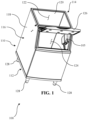
- the ice bin comprises a bin body 110.
- the bin body is comprised of a lower portion 112, an upper portion 114, and a perimeter wall 116.
- the perimeter wall 116 extends heightwise from the lower portion 112 to the upper portion 114.
- the perimeter wall 116 further comprises an outer shell 118 and a liner 120.
- the liner 120 defines an inner perimeter of the perimeter wall 116 and the outer shell 118 defines an outer perimeter of the perimeter wall.
- the liner 120 is disposed within the outer shell 118 and further defines an interior of the ice bin 100 for ice to be held for future use.
- the ice bin 100 further defines two openings, an ice drop opening 122 (broadly, ice drop area) and an ice retrieval opening 124 (broadly, ice retrieval area).
- the upper portion 114 surrounds the ice drop opening 122 and is configured to form a seat.
- the ice drop opening 122 is configured so that ice formed in an ice maker (not shown), supported above the ice bin 100 on the seat of the upper portion 114, is passable through the ice drop opening into the ice bin. Once the ice from the ice maker has passed through the ice drop opening 122, it rests in the interior of the liner 120 for future use. The ice is then retrieved from the interior of the liner 120 by a user through the ice retrieval opening 124.
- the ice retrieval opening is located generally at the front end of the ice bin 100, as illustrated in FIG. 1 .
- a door 126 is configured to operatively open and close the ice retrieval opening 124.
- the ice bin 100 is supported off of the ground using legs 128.
- FIG. 3 the left side of the outer shell 118 of the perimeter wall 116 is removed to show the area between the outer shell and the liner 120.
- FIG. 4 similarly shows the right side of the outer shell 118 of the perimeter wall 116 removed to show the area between the outer shell and the liner 120.
- the exterior surface of the liner 120 on either or both of the left or right side of the liner is configured to support a support plate 130.
- each support plate 130 is configured to support the scoop 105 on the inner wall of the bin 100 via a force of magnetic attraction between the support plate and the scoop.
- the support plate 130 can comprise a ferromagnetic material such as galvanized steel and the scoop 105 comprises a magnetic material configured to impart a force of magnetic attraction between the ferromagnetic scoop and the support plate.
- the support plate 130 comprises a magnet and the scoop 105 comprises ferromagnetic material such that the support plate 130 is configured to impart a force of magnetic attraction to the scoop for holding the scoop on the wall of the bin.
- the back edge margin of the support plate 130 is spaced apart from the back of the liner 120 by a front-to-back spacing distance D3 in an inclusive range of from about 8 inches to about 60.96 cm (e.g., from about 30.48 cm to about 45.72 cm).
- the front-to-back spacing distance is greater than the front-to-back depth D1 of the support plate.
- the liner 120 itself has a front-to-back depth D4.
- the front-to-back depth of the support plate D1 is in an inclusive range of from about 10% to about 75% of the front-to-back depth D4 of the liner (e.g., an inclusive range of from about 20% to about 50%).
- the front-to-back spacing distance D3 is in an inclusive range of from about 25% to about 90% of the depth D4 of the liner (e.g., an inclusive range of 50% to about 80%).
- the upper front corner region of each support plate 130 is beveled to match the angle of the doorframe around the ice retrieval opening 124.
- the support plate 130 has a top-to-bottom height H1 between a top edge margin and a bottom edge margin.
- the top-to-bottom height H1 is in an inclusive range from about 15.24 cm to about 91.44 cm (e.g., from about 20.32 cm to about 76.2 cm).
- the bottom edge margin of the support plate 130 is spaced apart from the bottom of the liner 120 by a top-to-bottom spacing distance H3 in an inclusive range of from about 30.48 cm to about 91.44 cm (e.g., from about 40.64 cm to about 76.2 cm).
- the top-to-bottom spacing distance H3 is greater than the top-to-bottom height distance H1.
- the liner 120 itself has a top-to-bottom height H4.
- the top-to-bottom height of the support plate H1 is in an inclusive range from about 10% to about 75% of the top-to-bottom height of the liner H4 (e.g., an inclusive range of from about 20% to about 50%).
- the top-to-bottom spacing distance H3 is in an inclusive range of from about 25% to about 90% of the top-to-bottom height of the liner H4 (e.g., an inclusive range of 50% to about 80%).
- the upper front corner region of each support plate 130 is beveled to match the angle of the frame around the ice retrieval opening 124.
- the top edge margin of the plate 130 has a height H2 below the bevel that is less than the overall height H1.
- the height H2 is an inclusive range of 10% to 90% of the height H1.
- the beveled edge defines an angle A1 with the front edge of the plate 130, measured as the outside angle between the front vertical edge and the bevel edge.
- the angle A1 is in an inclusive range of from about 190° to about 260°.
- the illustrated bin 105 further comprises double sided tape (broadly, an adhesive) between the plate 130 and the liner 120 that further supports the plate on the liner, and in particular, is configured to hold the plate in place the liner prior while the foamed insulation is being molded-in-place.
- the insulation layer keeps the temperature inside the liner 120 close to or below freezing and slows the drift toward warmer ambient temperature.
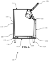
- the scoop 105 comprises a handle portion 138 and a scoop portion 140.
- the handle portion 138 has a distal end and a proximate end.
- the scoop portion 140 is attached to the distal end of the handle portion 138.
- the scoop portion 140 defines one or more magnetic receiving enclosures 144, and a magnetic element 146 (broadly, a magnetic attraction element, which in the illustrated embodiment comprises an element formed from a magnetic material; but as explained above, could, in other embodiments, comprise an element formed from ferromagnetic material) is received in each enclosure.
- a magnetic element 146 (broadly, a magnetic attraction element, which in the illustrated embodiment comprises an element formed from a magnetic material; but as explained above, could, in other embodiments, comprise an element formed from ferromagnetic material) is received in each enclosure.
- the enclosures 144 further comprise a cap 145, such that when the magnetic element 146 is placed into the magnet receiving enclosure, the cap is joined to the scoop 105 over the open end of the magnet receiving enclosure such that the cap retains the magnetic in the enclosure.
- the scoop 105 is made of plastic. It is contemplated that, in an alternative embodiment, if the bin support plates 130 were to comprise magnets instead of ferromagnetic material, the entire scoop 105 could be formed from ferromagnetic material such as galvanized steel instead of forming pockets for ferromagnetic elements.
- the illustrated magnetic elements 146 are configured to interact with the support plate 130 in order to support the scoop 105 against the interior wall of the liner 118 of the ice bin 100 in a position overlying the support plate, as seen in FIGS. 1 , 2 , 6 .
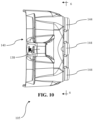
- the shell 118 comprises a sub-frame that supports perimeter wall panels of the shell.
- Each of the left and right sides of the shell 118 includes an upright frame member 150 of the sub-frame.
- a portion of the right panel wall is shown transparent to reveal the upright frame member 150, which would otherwise be hidden behind the panel wall.
- the upright frame member 150 is located closer to the front of the bin 100 than the back of the bin.
- the upright frame member 150 is formed from ferromagnetic material such as galvanized steel so that the scoop 105 can be supported on an exterior of the bin 100 by a force of magnetic attraction between the upright frame member and the magnetic elements 146 of the scoop.
- the ferromagnetic upright frame member 150 is immediately adjacent the panel wall of the shell and is separated from the liner 120 by insulation material.
- each of the support plates 130 is located immediately adjacent to the liner 120 and is spaced apart from the panel wall by insulation material.
- the support plates 130 enable the scoop 105 to be magnetically supported inside the bin 100, whereas the upright frame member 150 enables the scoop to be magnetically supported outside the bin.
- An ice machine (not shown) is supported above the upper portion of the ice bin 100 for forming ice and depositing ice into the bin.
- the ice machine drops the ice through the ice drop opening 122 defined by the upper portion 114 and into the interior ice bin 100 defined by a liner 120.
- the liner 120 houses the ice within the interior until a future user desires its use. While in the liner 120, the ice is hindered from melting due to an insulation layer (not shown) disposed between the outer shell 118 and the liner.
- the user opens the door 126.
- the scoop 105 In the initial position, the scoop 105 is supported in a position on the liner 120 overlying the support plate 130. In this initial position overlying the support plate 130, the scoop 105 is also out of the path of ice being dropped through the ice drop opening 122.
- the scoop 105 is supported onto the liner 120 through the force of magnetic attraction between magnetic elements 146 in the scoop and the ferromagnetic material of the support plate.
- the user grabs the handle 138 of the scoop 105, and by applying force, overcomes the magnetic force between the magnetic elements 146 of the scoop 105 and the support plate 130 and frees the scoop from its supported position on the liner 120. The user then scoops ice out of the liner 120 using the scoop 105.
- the ice collects in the bowl 140 of the scoop 105 to facilitate transfer of the ice to a desired location.
- the user places the scoop 105 in the area overlying the support plate 130 on the interior of the liner 120.
- the liner 120 has a marking indicating the location of the support plate 130 so that the user can visualize where to place the scoop.
- the magnetic force between the magnetic elements 146 and the support plate 130 once again supports the scoop 105 on the interior of the liner 120.
- the user may utilize the scoop 105 in substantially the same way, only with the scoop being supported on the exterior surface of the outer shell 118 in the area overlying the upright support member 150.
- the method according to claim 15 includes steps of forming a liner 120, forming the outer shell 118, temporarily supporting the support plates 130 on the liner via double-sided tape, and fitting the liner in the shell and support plates in the space between the liner and the shell.
- the particular order of these steps is not critical. So in one or more embodiments, the liner 120 can be formed, then the support plates 130 can be temporarily secured to the liner, and then the shell can be assembled around the liner.
- the liner 120 and outer shell 118 are each formed in suitable manufacturing processes, the support plates 130 are then temporarily secured to the liner, and then the assembly of the liner and the support plates is inserted into the shell.
- the liner 120 and outer shell 118 are each formed in suitable manufacturing processes, the liner is then slipped into the outer shell, and then the plates are temporarily secured to the liner in the space between the liner and shell. Any suitable manufacturing processes can be used to form the liner 120 and the shell 118.
- the liner 120 is formed in a blow molding process, from blow-molded plastic.
- the shell 118 may suitably be formed by assembling a sub-frame and then securing outer shell wall panels to the sub-frame vial suitable fasteners or mechanical tabs or hooks.
- the support plate 130 is temporarily fitted onto the liner 120 using an adhesive (e.g., a double-sided tape).
- an insulation layer is foamed in the space between the outer shell and the liner in order to insulate the bin 100 and permanently secure the support plate in position.
- Curable insulation material is imparted into the space so that it substantially fills the space and conforms to the support plates 130. The insulation material is then cured to provide a firm hold of the support plate 130 in the desired position.
- the method includes forming a scoop 105 comprising a magnetic element receiving enclosure 144 having an open end, placing a magnetic element 146 into the magnetic element receiving enclosure through the open end, and joining a cap 145 to the scoop 105 over the open end of the magnetic element receiving enclosure such that the cap retains the magnetic element in the enclosure.
- the joining of the cap 145 comprises ultrasonic welding the cap to the scoop 105.
- the scoop 105 may be formed by molding the scoop, and the scoop is preferably comprised of plastic.
- the illustrated bin 100 and scoop 105 are believed to provide a much more convenient, user-friendly mechanism for supporting the scoop.
- the inventors have recognized that scoop-holding brackets inside an ice bin are often difficult to use (particularly for uses with physical limitations due to injury or disability) because they only allow the user to support the scoop at a particular location and orientation.
- the illustrated support plates 130 provide a wide range of possibilities for where and how a user can support the scoop 105 on the side wall of the bin, out of contact with the ice and out of the way of ice maker operation.
- the ice bin is integrated with the ice maker 265, as is the case with the residential-style ice maker, generally indicated at 200.
- the residential ice maker includes a bin body 210 comprising a front door assembly 260 configured to releasably support the magnetic scoop 105 discussed above.
- the illustrated door assembly 260 is configured to mount on the bin body 210 with hinges to swing open and closed.
- the door assembly 260 comprises a shell 218 and a liner 220 defining a space therebetween configured to receive insulation. Similar to the bin body 110 discussed above, the illustrated door assembly comprises a support plate 230 secured to the liner 220.
- the support plate 230 is configured to align with an opening through which the user withdraws ice from the ice maker appliances when the door is open.
- the support plate 230 is temporarily secured to the liner 220 with tape and then foamed into place for a permanent installation (similar to the support plate 130 described above).
- the support plate 230 allows the magnetic scoop 105 to support itself on the door assembly 260 at a position that still allows the door to open and close.
- the user can open the door 260, separate the scoop 105 from the door, withdraw ice from the residential ice bin 200, return the scoop to the door such that scoop is supported on the door by a force of magnetic attraction between the scoop and the door, and finally shut the door.
Landscapes
- Engineering & Computer Science (AREA)
- Physics & Mathematics (AREA)
- Mechanical Engineering (AREA)
- Thermal Sciences (AREA)
- General Engineering & Computer Science (AREA)
- Refrigerator Housings (AREA)
- Packages (AREA)
- Manipulator (AREA)
- Production, Working, Storing, Or Distribution Of Ice (AREA)
Claims (15)
- Eisbehälter (100), umfassend:
einen Behälterkörper (110), umfassend einen unteren Abschnitt (112), einen oberen Abschnitt (114) und eine Umfangswand (116), die sich in Höhenrichtung von dem unteren Abschnitt zu dem oberen Abschnitt erstreckt, wobei der obere Abschnitt des Behälterkörpers einen Eisabwurfbereich (122) definiert, der derart konfiguriert ist, dass von einem über dem Eisbehälter gehaltenen Eisbereiter abgeworfenes Eis durch den Eisabwurfbereich in das Innere gelangen kann, wobei der Behälterkörper ferner einen von dem Eisabwurfbereich beabstandeten Eisentnahmebereich (124) zum Bereitstellen von Zugang zu dem Inneren des Eisbehälters umfasst, dadurch gekennzeichnet, dass die Umfangswand eine Halteplatte (130) umfasst, die dazu konfiguriert ist, eine Eisschaufel (105) an der Umfangswand in dem Inneren des Eisbehälters durch eine magnetische Anziehungskraft zwischen der Eisschaufel und der Halteplatte zu halten, wobei der Eisbehälter (100) ferner ein senkrechtes Rahmenelement (150) umfasst, das aus ferromagnetischem Material gebildet ist, sodass die Eisschaufel durch magnetische Anziehungskraft zwischen dem senkrechten Rahmenelement und der Eisschaufel an einem Äußeren des Eisbehälters gehalten werden kann. - Eisbehälter nach Anspruch 1, wobei die Halteplatte aus einem von entweder einem ferromagnetischen Material oder einem magnetischen Material besteht.
- Eisbehälter nach einem der Ansprüche 1 und 2, wobei die Umfangswand eine äußere Hülle (118) und eine Auskleidung (120) umfasst, wobei die Auskleidung innerhalb der äußeren Hülle angeordnet ist.
- Eisbehälter nach Anspruch 3, wobei die Halteplatte in einem Zwischenraum zwischen der Auskleidung und der äußeren Hülle an der Auskleidung gehalten wird.
- Eisbehälter nach Anspruch 4, ferner umfassend doppelseitiges Band, das die Halteplatte mit der Auskleidung verbindet.
- Eisbehälter nach einem der Ansprüche 4 und 5, wobei die Halteplatte an der vorderen oberen Ecke einer Seite der Auskleidung positioniert ist.
- Eisbehälter nach einem der Ansprüche 3-6, wobei die Halteplatte einen Vorderkantenrand und einen Hinterkantenrand aufweist und eine Tiefe von vorne nach hinten aufweist, die sich von dem Vorderkantenrand zu dem Hinterkantenrand erstreckt, wobei optional die Tiefe von vorne nach hinten der Halteplatte in einem inklusiven Bereich von etwa 20,32 cm bis etwa 60,96 cm liegt.
- Eisbehälter nach einem der Ansprüche 3-7, wobei die Halteplatte einen Vorderkantenrand und einen Hinterkantenrand aufweist und eine Tiefe von vorne nach hinten aufweist, die sich von dem Vorderkantenrand zu dem Hinterkantenrand erstreckt, wobei optional die Auskleidung eine Vorderseite und eine Rückseite und eine Tiefe von vorne nach hinten aufweist, wobei die Tiefe von vorne nach hinten der Halteplatte mindestens etwa 10 % der Tiefe von vorne nach hinten der Auskleidung beträgt.
- Eisbehälter nach einem der Ansprüche 3-8, wobei die Halteplatte einen Oberkantenrand, einen Unterkantenrand und eine sich von dem Oberkantenrand zu dem Unterkantenrand erstreckende Höhe aufweist, wobei optional die Höhe der Halteplatte in einem inklusiven Bereich von etwa 30,48 cm bis etwa 91,44 cm liegt.
- Eisbehälter nach einem der Ansprüche 3-9, wobei die Halteplatte einen Oberkantenrand, einen Unterkantenrand und eine sich von dem Oberkantenrand zu dem Unterkantenrand erstreckende Höhe aufweist, wobei optional die Auskleidung eine Oberseite und eine Unterseite und eine sich von der Unterseite zu der Oberseite erstreckende Höhe aufweist, wobei die Höhe der Halteplatte mindestens etwa 10 % der Höhe der Auskleidung beträgt.
- Eisbehälter nach einem der Ansprüche 3-10, wobei die Umfangswand ferner eine Isolierschicht umfasst, wobei die Isolierschicht zwischen der Auskleidung und der äußeren Hülle angeordnet ist.
- Eisbehälter nach Anspruch 11, wobei die Isolierschicht zwischen der Auskleidung und der äußeren Hülle um die Halteplatte eingespritzte Isolierung umfasst.
- Eisaufbewahrungs- und -entnahmeanordnung, umfassend:einen Eisbehälter (100) nach einem der vorangehenden Ansprüche undeine mindestens ein magnetisches oder ferromagnetisches Element umfassende Eisschaufel (105), wobei die Eisschaufel dazu konfiguriert ist, sich an einer die Halteplatte überlagernden Stelle im Inneren des Eisbehälters durch magnetische Anziehungskraft zwischen der Eisschaufel und der Halteplatte selbst an der Umfangswand zu halten, oder wobei die Eisschaufel (105) dazu konfiguriert ist, sich durch magnetische Anziehungskraft zwischen dem senkrechten Rahmenelement (150) und der Eisschaufel (105) selbst an einem Äußeren des Eisbehälters zu halten.
- Eisaufbewahrungs- und -entnahmeanordnung nach Anspruch 13, wobei die Eisschaufel (105) mindestens einen umschlossenen Hohlraum und ein magnetisches oder ferromagnetisches Element umfasst, wobei das magnetische oder ferromagnetische Element innerhalb des umschlossenen Hohlraums angeordnet ist.
- Verfahren zum Herstellen eines Eisbehälters (100) nach einem der vorangehenden Ansprüche, wobei das Verfahren Folgendes umfasst:vorübergehendes Halten einer Halteplatte an einer Auskleidung des Eisbehälters in einem Zwischenraum zwischen der Auskleidung und einer äußeren Hülle des Eisbehälters;Füllen des Zwischenraums zwischen der Auskleidung und der äußeren Hülle mit härtbarer Isolierung, sodass die härtbare Isolierung sich an die Form der Halteplatte anpasst; undHärten der härtbaren Isolierung, sodass die Isolierung die Halteplatte in dem Zwischenraum zwischen der Auskleidung und der äußeren Hülle hält.
Priority Applications (1)
| Application Number | Priority Date | Filing Date | Title |
|---|---|---|---|
| EP25164267.4A EP4575359A3 (de) | 2021-05-12 | 2022-05-10 | Eisbehälter, magnetisierte schaufel für einen eisbehälter und verfahren zur herstellung von einem eisbehälter |
Applications Claiming Priority (1)
| Application Number | Priority Date | Filing Date | Title |
|---|---|---|---|
| US17/318,486 US12320570B2 (en) | 2021-05-12 | 2021-05-12 | Ice bin with magnetized scoop and method of manufacture and use |
Related Child Applications (1)
| Application Number | Title | Priority Date | Filing Date |
|---|---|---|---|
| EP25164267.4A Division EP4575359A3 (de) | 2021-05-12 | 2022-05-10 | Eisbehälter, magnetisierte schaufel für einen eisbehälter und verfahren zur herstellung von einem eisbehälter |
Publications (3)
| Publication Number | Publication Date |
|---|---|
| EP4089350A1 EP4089350A1 (de) | 2022-11-16 |
| EP4089350C0 EP4089350C0 (de) | 2025-03-19 |
| EP4089350B1 true EP4089350B1 (de) | 2025-03-19 |
Family
ID=81603671
Family Applications (2)
| Application Number | Title | Priority Date | Filing Date |
|---|---|---|---|
| EP22172623.5A Active EP4089350B1 (de) | 2021-05-12 | 2022-05-10 | Eisbehälter, magnetisierte schaufel für einen eisbehälter und verfahren zur herstellung von einem eisbehälter |
| EP25164267.4A Pending EP4575359A3 (de) | 2021-05-12 | 2022-05-10 | Eisbehälter, magnetisierte schaufel für einen eisbehälter und verfahren zur herstellung von einem eisbehälter |
Family Applications After (1)
| Application Number | Title | Priority Date | Filing Date |
|---|---|---|---|
| EP25164267.4A Pending EP4575359A3 (de) | 2021-05-12 | 2022-05-10 | Eisbehälter, magnetisierte schaufel für einen eisbehälter und verfahren zur herstellung von einem eisbehälter |
Country Status (9)
| Country | Link |
|---|---|
| US (2) | US12320570B2 (de) |
| EP (2) | EP4089350B1 (de) |
| JP (1) | JP2022176096A (de) |
| KR (1) | KR20220154018A (de) |
| CN (1) | CN115420044A (de) |
| AU (1) | AU2022202846A1 (de) |
| CA (1) | CA3157164A1 (de) |
| ES (1) | ES3031291T3 (de) |
| MX (1) | MX2022004782A (de) |
Citations (1)
| Publication number | Priority date | Publication date | Assignee | Title |
|---|---|---|---|---|
| US20170121075A1 (en) * | 2015-11-02 | 2017-05-04 | Mead Johnson Nutrition Company | Magnetic measuring device and container |
Family Cites Families (22)
| Publication number | Priority date | Publication date | Assignee | Title |
|---|---|---|---|---|
| JP3828607B2 (ja) | 1996-03-11 | 2006-10-04 | ホシザキ電機株式会社 | 貯氷庫付き製氷機のスコップ収納機構 |
| ES2242259T3 (es) | 1997-04-22 | 2005-11-01 | Manitowoc Foodservice Companies, Inc. | Conjunto de deposito para hielo. |
| US6250696B1 (en) | 2000-05-05 | 2001-06-26 | Rhonda M. Baker | Clothes stick apparatus |
| US20050236406A1 (en) | 2001-02-15 | 2005-10-27 | Integral Technologies, Inc. | Low cost food processing, preparation, and handling devices manufactured from conductive loaded resin-based materials |
| US6742821B2 (en) | 2001-02-27 | 2004-06-01 | Arthur Kleinpell | Food scoop |
| JP2004057227A (ja) | 2002-07-24 | 2004-02-26 | Toshiba Home Technology Corp | しゃもじ |
| JP2004121792A (ja) | 2002-10-03 | 2004-04-22 | Koji Ashida | 磁石内蔵のお玉置き器 |
| CN2578055Y (zh) | 2002-10-17 | 2003-10-08 | 谢智庆 | 可被工作物吸附的工具握柄 |
| JP2004202612A (ja) | 2002-12-24 | 2004-07-22 | Chikei Sha | 工具持ち手の磁性製造法 |
| US20050056655A1 (en) | 2003-09-15 | 2005-03-17 | Gary Lonnie F. | Magnetic beverage holder |
| US7503212B2 (en) | 2004-01-27 | 2009-03-17 | Dalla Piazza & Co. | Adjustable measuring scoop |
| US7043844B2 (en) | 2004-07-28 | 2006-05-16 | Mu Hsiang Lin | Magnetic attractable spoon |
| WO2011088220A1 (en) | 2010-01-13 | 2011-07-21 | Progressive International Corporation | Magnetic peeler set |
| CN201658164U (zh) | 2010-04-07 | 2010-12-01 | 陈建明 | 磁性汤匙 |
| US8505420B2 (en) | 2010-06-21 | 2013-08-13 | Nelson B. Alfaro | Magnetized hand tools |
| US20120280525A1 (en) | 2011-05-05 | 2012-11-08 | Jannie Lou Tharp | Scoop set |
| US10279980B2 (en) | 2011-07-27 | 2019-05-07 | Lewis William James, JR. | Magnetic thermally insulated enclosure |
| JP2013087996A (ja) | 2011-10-14 | 2013-05-13 | Hoshizaki Electric Co Ltd | 製氷機のスコップ保持構造 |
| US9187224B1 (en) | 2012-11-28 | 2015-11-17 | Joseph C Mazzilli | Magnetically held spoon or scooper on a lid of a container and method |
| US9493271B2 (en) | 2014-03-04 | 2016-11-15 | The Mentality, LLC | Scoop retention device |
| CN204963371U (zh) | 2015-08-19 | 2016-01-13 | 合肥华凌股份有限公司 | 制冷设备 |
| US10174984B2 (en) | 2016-09-01 | 2019-01-08 | Follett Corporation | Ice making system with provision for cleaning and cleaning method |
-
2021
- 2021-05-12 US US17/318,486 patent/US12320570B2/en active Active
-
2022
- 2022-04-08 JP JP2022064544A patent/JP2022176096A/ja active Pending
- 2022-04-21 MX MX2022004782A patent/MX2022004782A/es unknown
- 2022-04-22 CA CA3157164A patent/CA3157164A1/en active Pending
- 2022-04-29 AU AU2022202846A patent/AU2022202846A1/en active Pending
- 2022-05-02 KR KR1020220054011A patent/KR20220154018A/ko active Pending
- 2022-05-10 ES ES22172623T patent/ES3031291T3/es active Active
- 2022-05-10 EP EP22172623.5A patent/EP4089350B1/de active Active
- 2022-05-10 EP EP25164267.4A patent/EP4575359A3/de active Pending
- 2022-05-11 CN CN202210509923.4A patent/CN115420044A/zh active Pending
-
2025
- 2025-05-06 US US19/199,608 patent/US20250264258A1/en active Pending
Patent Citations (1)
| Publication number | Priority date | Publication date | Assignee | Title |
|---|---|---|---|---|
| US20170121075A1 (en) * | 2015-11-02 | 2017-05-04 | Mead Johnson Nutrition Company | Magnetic measuring device and container |
Also Published As
| Publication number | Publication date |
|---|---|
| US12320570B2 (en) | 2025-06-03 |
| CN115420044A (zh) | 2022-12-02 |
| AU2022202846A1 (en) | 2022-12-01 |
| US20250264258A1 (en) | 2025-08-21 |
| EP4089350C0 (de) | 2025-03-19 |
| US20220364779A1 (en) | 2022-11-17 |
| EP4575359A3 (de) | 2025-08-20 |
| EP4575359A2 (de) | 2025-06-25 |
| CA3157164A1 (en) | 2022-11-12 |
| JP2022176096A (ja) | 2022-11-25 |
| ES3031291T3 (en) | 2025-07-07 |
| MX2022004782A (es) | 2022-11-14 |
| EP4089350A1 (de) | 2022-11-16 |
| KR20220154018A (ko) | 2022-11-21 |
Similar Documents
| Publication | Publication Date | Title |
|---|---|---|
| JP2571700B2 (ja) | 耐火容器の組み立て方法 | |
| US4766740A (en) | Container for the preservation and transportation of severed limbs or other body parts | |
| WO2001010767A2 (en) | Cooler with beverage dispenser | |
| US5009083A (en) | Beverage cooler | |
| US8016160B2 (en) | Refrigerator related technology | |
| US20040040212A1 (en) | Door opening and closing mechanism with dual pivot axes for a door | |
| EP2116799A2 (de) | Kühlschrank mit Kaltlagerungseinheit | |
| KR20050026740A (ko) | 디스펜서를 구비한 냉장고 | |
| MXPA04003411A (es) | Dispositivo para la fabricacion de hielos en gabinetes refrigerados. | |
| US10407211B2 (en) | Automatically closing dispenser | |
| EP4089350B1 (de) | Eisbehälter, magnetisierte schaufel für einen eisbehälter und verfahren zur herstellung von einem eisbehälter | |
| US7418831B2 (en) | Refrigerator with diagonal ice chute dispenser | |
| US4845886A (en) | Fish cooler access means | |
| HK40083881A (en) | Ice bin with magnetized scoop and method of manufacture and use | |
| US20070290001A1 (en) | Portable beverage dispensing apparatus | |
| JPS6027350Y2 (ja) | 冷蔵庫 | |
| WO2017026133A1 (ja) | 飲料供給装置及び冷蔵庫 | |
| JP6607732B2 (ja) | 飲料供給装置及び冷蔵庫 | |
| JP6950069B1 (ja) | 冷蔵庫 | |
| KR101778933B1 (ko) | 저장용기 및 이를 구비한 김치저장고 | |
| JPS6240306Y2 (de) | ||
| JP3024967U (ja) | 脱臭剤容器 | |
| EP2778578B1 (de) | Vakuumisolierte Türstruktur und Verfahren zur Herstellung davon | |
| CN220119620U (zh) | 制冰机 | |
| KR200188022Y1 (ko) | 휴대용 냉보온 물통 |
Legal Events
| Date | Code | Title | Description |
|---|---|---|---|
| PUAI | Public reference made under article 153(3) epc to a published international application that has entered the european phase |
Free format text: ORIGINAL CODE: 0009012 |
|
| STAA | Information on the status of an ep patent application or granted ep patent |
Free format text: STATUS: THE APPLICATION HAS BEEN PUBLISHED |
|
| AK | Designated contracting states |
Kind code of ref document: A1 Designated state(s): AL AT BE BG CH CY CZ DE DK EE ES FI FR GB GR HR HU IE IS IT LI LT LU LV MC MK MT NL NO PL PT RO RS SE SI SK SM TR |
|
| STAA | Information on the status of an ep patent application or granted ep patent |
Free format text: STATUS: REQUEST FOR EXAMINATION WAS MADE |
|
| 17P | Request for examination filed |
Effective date: 20230427 |
|
| RBV | Designated contracting states (corrected) |
Designated state(s): AL AT BE BG CH CY CZ DE DK EE ES FI FR GB GR HR HU IE IS IT LI LT LU LV MC MK MT NL NO PL PT RO RS SE SI SK SM TR |
|
| GRAP | Despatch of communication of intention to grant a patent |
Free format text: ORIGINAL CODE: EPIDOSNIGR1 |
|
| STAA | Information on the status of an ep patent application or granted ep patent |
Free format text: STATUS: GRANT OF PATENT IS INTENDED |
|
| INTG | Intention to grant announced |
Effective date: 20241016 |
|
| GRAS | Grant fee paid |
Free format text: ORIGINAL CODE: EPIDOSNIGR3 |
|
| GRAA | (expected) grant |
Free format text: ORIGINAL CODE: 0009210 |
|
| STAA | Information on the status of an ep patent application or granted ep patent |
Free format text: STATUS: THE PATENT HAS BEEN GRANTED |
|
| AK | Designated contracting states |
Kind code of ref document: B1 Designated state(s): AL AT BE BG CH CY CZ DE DK EE ES FI FR GB GR HR HU IE IS IT LI LT LU LV MC MK MT NL NO PL PT RO RS SE SI SK SM TR |
|
| REG | Reference to a national code |
Ref country code: GB Ref legal event code: FG4D |
|
| REG | Reference to a national code |
Ref country code: CH Ref legal event code: EP |
|
| REG | Reference to a national code |
Ref country code: IE Ref legal event code: FG4D |
|
| REG | Reference to a national code |
Ref country code: DE Ref legal event code: R096 Ref document number: 602022011855 Country of ref document: DE |
|
| U01 | Request for unitary effect filed |
Effective date: 20250417 |
|
| U07 | Unitary effect registered |
Designated state(s): AT BE BG DE DK EE FI FR IT LT LU LV MT NL PT RO SE SI Effective date: 20250424 |
|
| PG25 | Lapsed in a contracting state [announced via postgrant information from national office to epo] |
Ref country code: RS Free format text: LAPSE BECAUSE OF FAILURE TO SUBMIT A TRANSLATION OF THE DESCRIPTION OR TO PAY THE FEE WITHIN THE PRESCRIBED TIME-LIMIT Effective date: 20250619 |
|
| REG | Reference to a national code |
Ref country code: ES Ref legal event code: FG2A Ref document number: 3031291 Country of ref document: ES Kind code of ref document: T3 Effective date: 20250707 |
|
| PG25 | Lapsed in a contracting state [announced via postgrant information from national office to epo] |
Ref country code: NO Free format text: LAPSE BECAUSE OF FAILURE TO SUBMIT A TRANSLATION OF THE DESCRIPTION OR TO PAY THE FEE WITHIN THE PRESCRIBED TIME-LIMIT Effective date: 20250619 |
|
| PG25 | Lapsed in a contracting state [announced via postgrant information from national office to epo] |
Ref country code: HR Free format text: LAPSE BECAUSE OF FAILURE TO SUBMIT A TRANSLATION OF THE DESCRIPTION OR TO PAY THE FEE WITHIN THE PRESCRIBED TIME-LIMIT Effective date: 20250319 |
|
| PG25 | Lapsed in a contracting state [announced via postgrant information from national office to epo] |
Ref country code: GR Free format text: LAPSE BECAUSE OF FAILURE TO SUBMIT A TRANSLATION OF THE DESCRIPTION OR TO PAY THE FEE WITHIN THE PRESCRIBED TIME-LIMIT Effective date: 20250620 |
|
| U20 | Renewal fee for the european patent with unitary effect paid |
Year of fee payment: 4 Effective date: 20250628 |
|
| PG25 | Lapsed in a contracting state [announced via postgrant information from national office to epo] |
Ref country code: SM Free format text: LAPSE BECAUSE OF FAILURE TO SUBMIT A TRANSLATION OF THE DESCRIPTION OR TO PAY THE FEE WITHIN THE PRESCRIBED TIME-LIMIT Effective date: 20250319 |
|
| PGFP | Annual fee paid to national office [announced via postgrant information from national office to epo] |
Ref country code: ES Payment date: 20250701 Year of fee payment: 4 |
|
| PG25 | Lapsed in a contracting state [announced via postgrant information from national office to epo] |
Ref country code: PL Free format text: LAPSE BECAUSE OF FAILURE TO SUBMIT A TRANSLATION OF THE DESCRIPTION OR TO PAY THE FEE WITHIN THE PRESCRIBED TIME-LIMIT Effective date: 20250319 |
|
| PG25 | Lapsed in a contracting state [announced via postgrant information from national office to epo] |
Ref country code: CZ Free format text: LAPSE BECAUSE OF FAILURE TO SUBMIT A TRANSLATION OF THE DESCRIPTION OR TO PAY THE FEE WITHIN THE PRESCRIBED TIME-LIMIT Effective date: 20250319 |
|
| PG25 | Lapsed in a contracting state [announced via postgrant information from national office to epo] |
Ref country code: SK Free format text: LAPSE BECAUSE OF FAILURE TO SUBMIT A TRANSLATION OF THE DESCRIPTION OR TO PAY THE FEE WITHIN THE PRESCRIBED TIME-LIMIT Effective date: 20250319 |
|
| PG25 | Lapsed in a contracting state [announced via postgrant information from national office to epo] |
Ref country code: IS Free format text: LAPSE BECAUSE OF FAILURE TO SUBMIT A TRANSLATION OF THE DESCRIPTION OR TO PAY THE FEE WITHIN THE PRESCRIBED TIME-LIMIT Effective date: 20250719 |
|
| REG | Reference to a national code |
Ref country code: CH Ref legal event code: H13 Free format text: ST27 STATUS EVENT CODE: U-0-0-H10-H13 (AS PROVIDED BY THE NATIONAL OFFICE) Effective date: 20251223 |
|
| PG25 | Lapsed in a contracting state [announced via postgrant information from national office to epo] |
Ref country code: CH Free format text: LAPSE BECAUSE OF NON-PAYMENT OF DUE FEES Effective date: 20250531 |
|
| PLBE | No opposition filed within time limit |
Free format text: ORIGINAL CODE: 0009261 |
|
| STAA | Information on the status of an ep patent application or granted ep patent |
Free format text: STATUS: NO OPPOSITION FILED WITHIN TIME LIMIT |
|
| REG | Reference to a national code |
Ref country code: CH Ref legal event code: L10 Free format text: ST27 STATUS EVENT CODE: U-0-0-L10-L00 (AS PROVIDED BY THE NATIONAL OFFICE) Effective date: 20260128 |
|
| PG25 | Lapsed in a contracting state [announced via postgrant information from national office to epo] |
Ref country code: MC Free format text: LAPSE BECAUSE OF FAILURE TO SUBMIT A TRANSLATION OF THE DESCRIPTION OR TO PAY THE FEE WITHIN THE PRESCRIBED TIME-LIMIT Effective date: 20250319 |