EP4089256A1 - Concealed door handle and vehicle - Google Patents
Concealed door handle and vehicle Download PDFInfo
- Publication number
- EP4089256A1 EP4089256A1 EP22165069.0A EP22165069A EP4089256A1 EP 4089256 A1 EP4089256 A1 EP 4089256A1 EP 22165069 A EP22165069 A EP 22165069A EP 4089256 A1 EP4089256 A1 EP 4089256A1
- Authority
- EP
- European Patent Office
- Prior art keywords
- microswitch
- handle
- concealed door
- deployment
- door handle
- Prior art date
- Legal status (The legal status is an assumption and is not a legal conclusion. Google has not performed a legal analysis and makes no representation as to the accuracy of the status listed.)
- Pending
Links
- 230000001960 triggered effect Effects 0.000 claims abstract description 29
- 238000004891 communication Methods 0.000 claims abstract description 7
- 230000008859 change Effects 0.000 description 5
- 230000007246 mechanism Effects 0.000 description 4
- 230000003321 amplification Effects 0.000 description 3
- 238000010586 diagram Methods 0.000 description 3
- 238000003199 nucleic acid amplification method Methods 0.000 description 3
- 238000001514 detection method Methods 0.000 description 2
- 238000013461 design Methods 0.000 description 1
- 238000011161 development Methods 0.000 description 1
- 238000005516 engineering process Methods 0.000 description 1
- 230000009191 jumping Effects 0.000 description 1
- 238000000034 method Methods 0.000 description 1
- 238000012986 modification Methods 0.000 description 1
- 230000004048 modification Effects 0.000 description 1
- 230000008569 process Effects 0.000 description 1
- 230000002123 temporal effect Effects 0.000 description 1
Images
Classifications
-
- E—FIXED CONSTRUCTIONS
- E05—LOCKS; KEYS; WINDOW OR DOOR FITTINGS; SAFES
- E05B—LOCKS; ACCESSORIES THEREFOR; HANDCUFFS
- E05B85/00—Details of vehicle locks not provided for in groups E05B77/00 - E05B83/00
- E05B85/10—Handles
- E05B85/103—Handles creating a completely closed wing surface
-
- E—FIXED CONSTRUCTIONS
- E05—LOCKS; KEYS; WINDOW OR DOOR FITTINGS; SAFES
- E05B—LOCKS; ACCESSORIES THEREFOR; HANDCUFFS
- E05B85/00—Details of vehicle locks not provided for in groups E05B77/00 - E05B83/00
- E05B85/10—Handles
- E05B85/107—Pop-out handles, e.g. sliding outwardly before rotation
-
- E—FIXED CONSTRUCTIONS
- E05—LOCKS; KEYS; WINDOW OR DOOR FITTINGS; SAFES
- E05B—LOCKS; ACCESSORIES THEREFOR; HANDCUFFS
- E05B81/00—Power-actuated vehicle locks
- E05B81/02—Power-actuated vehicle locks characterised by the type of actuators used
- E05B81/04—Electrical
-
- E—FIXED CONSTRUCTIONS
- E05—LOCKS; KEYS; WINDOW OR DOOR FITTINGS; SAFES
- E05B—LOCKS; ACCESSORIES THEREFOR; HANDCUFFS
- E05B81/00—Power-actuated vehicle locks
- E05B81/54—Electrical circuits
- E05B81/64—Monitoring or sensing, e.g. by using switches or sensors
- E05B81/76—Detection of handle operation; Detection of a user approaching a handle; Electrical switching actions performed by door handles
Definitions
- the invention relates to the technical field of vehicle accessories, and in particular, to a concealed door handle and a vehicle.
- the concealed door handle To monitor and control deployed and retracted positions of the concealed door handle, the concealed door handle needs to send its own position state signal to a vehicle control unit or a domain controller in real time. Under normal operation conditions, an electronic lock can only be unlocked to open the door by using an electronic signal as an input. Only under emergency conditions, can the electronic lock be unlocked to open the door by means of a mechanical key and under the drive of a physical pull-wire. Therefore, it is necessary for the door handle to detect a manual operation of a user and send an electronic signal to the vehicle control unit or the domain controller.
- a Hall sensor is used to monitor a rotation angle of the concealed handle throughout the process.
- the vehicle control unit or the domain controller drives the electronic lock to be unlocked to open the door.
- the Hall sensor it is necessary to add a magnetic ring on a rotating shaft of the rotating structure to be monitored, and the number of magnetic poles of the magnetic ring is generally not greater than eight. Since one circle of rotation is 360°, even if a magnetic ring with 8 magnetic poles is used, the smallest unit that can be detected is 45°.
- an additional rotation angle amplification mechanism is specially designed (for example, the rotation angle change is amplified by means of a gear or a gear set).
- the additional rotation angle amplification mechanism can be designed to generate a larger angle change, and the Hall sensor may be arranged on the rotation angle amplification mechanism, so that every change by 45° of the rotation angle magnification mechanism can reflect the small angle change of the handgrip.
- this type of design essentially brings additional unnecessary elements that are not related to the implementation of the basic function, increasing the complexity of the part.
- the cost of the Hall sensor itself and the magnetic ring is high, and an additional PCB circuit is also required. Therefore, the first option has higher costs.
- Microswitches are used in the second option: multiple independent microswitches are respectively applied to determine the state of the handle, i.e.
- the concealed door handle comprises:
- the concealed door handle further comprises a retraction microswitch configured to detect a retracted position of the handle body and to maintain communication with the vehicle control module, the retraction microswitch being arranged on the handle base.
- the handle body has the retracted position, the deployed position and a release position in sequence as the position of a rear end of the handle body changes from inside to outside;
- the handle body further comprises a fault state; and when the handle body is in the fault state, the deployment microswitch and the retraction microswitch are both triggered.
- the deployment microswitch comprises a microswitch trigger block, which has a recess configured for signal jump.
- the handle body has a contact face, which forms a contactable connection with a side face of the microswitch trigger block that has the recess.
- the microswitch trigger block is rotatable about a length direction of the handle base.
- the deployment microswitch jumps from the triggered state into the untriggered state and sents the input signal for unlocking the electronic lock
- the unlocking of an electronic door lock of the vehicle is commanded by the vehicle control module.
- the concealed door handle is a swing-out concealed door handle or a slide-out concealed door handle.
- a vehicle comprising the concealed door handle described above.
- the concealed door handle of the invention can not only simplify the structure of the part and reduce the number of sub-parts, but can also meet the same functional requirements with lower costs.
- first, second, etc. used to describe various elements are not intended to limit the positional, temporal or importance relationship of these elements, but rather only to distinguish one component from the other.
- first element and the second element may refer to the same instance of the element, and in some cases, based on contextual descriptions, the first element and the second element may also refer to different instances.
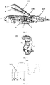
- FIG. 1 A schematic structural diagram of a concealed door handle according to an embodiment of the invention is shown in Fig. 1 .
- the concealed door handle 100 is composed of a handle body 110, a handle base 120, a deployment microswitch 130 and other components.
- the handle base 120 is fixed in a body of a vehicle.
- the handle body 110 is concealed in the handle base 120, and the handle body 110 is rotatably connected to the handle base 120.
- the deployment microswitch 130 is arranged on the handle base 120 and configured to detect a deployed position of the handle body 110 and to maintain communication with a vehicle control module.
- the deployment microswitch 130 When the deployment microswitch 130 jumps from a triggered state into an untriggered state, the deployment microswitch 130 sends an input signal for unlocking an electronic lock to the vehicle control module.
- the state detection microswitch of the electric deployed position of the concealed door handle is also used as an signal input of the electronic lock for manually opening a door, and the two signals are advantageously obtained by the same mechanical structure, thereby simplifying the structure of the concealed door handle and reducing the number of parts.
- the concealed door handle further comprises a retraction microswitch (not shown) configured to detect a retracted position of the handle body 110 and to maintain communication with the vehicle control module.
- the retraction microswitch is arranged on the handle base 120.
- the handle body 110 has the retracted position A, the deployed position B and a release position C in sequence as the position of a rear end of the handle body changes from inside to outside.
- the handle body 110 When the handle body 110 is in the retracted position A, the deployment microswitch 130 is not triggered, and the retraction microswitch is triggered. In this case, the handle body 110 is located in the handle base 120.
- the deployment microswitch 130 is triggered, and the retraction microswitch is not triggered. In this case, an operator pulls the handle body 110 to unlock the vehicle door.
- the handle body 110 further comprises a fault state.
- the deployment microswitch 130 and the retraction microswitch are both triggered. In this case, since the deployment microswitch 130 and the retraction microswitch are both triggered, the handle body 110 cannot operate normally.
- the deployment microswitch comprises a microswitch trigger block 131 (see Figs. 2 and 3 ), and the microswitch trigger block 131 has a distinct recess 132 configured for signal jump. As shown in Fig. 3 , the microswitch trigger block 131 has a triggered region Y corresponding to the recess 132, and untriggered regions X.
- the handle body has a contact face 110, which forms a contactable connection with a side face (the triggered region Y) of the microswitch trigger block 131 that has the recess 132.
- the microswitch trigger block 131 is rotatable about a length direction of the handle base. As shown in Fig. 1 , the microswitch trigger block 131 has a microswitch trigger block retracted position a, a microswitch trigger block deployed position b and a microswitch trigger block release position c in sequence as the position of the rear end of the handle body changes from inside to outside.
- the unlocking of an electronic door lock of the vehicle is commanded by the vehicle control module.
- a vehicle there is also provided a vehicle.
- the vehicle of the embodiment of the invention may comprise the concealed door handle described above.
- the concealed door handle described above may be mounted on a vehicle door of the vehicle.
- the vehicle is considered to be a type of motor vehicle, for example, refers to a car, a coach, a truck, or a commercial vehicle.
- the invention is not limited to this type of vehicle.
- the concealed door handle according to the invention has the advantages of simplified structure and low costs, and effectively solves the problem of arranging a signal source in a limited structural space.
- the concealed door handle is a swing-out concealed door handle or a slide-out concealed door handle. Therefore, all equivalent technical solutions should fall within the scope of the invention and be defined by the claims of the invention.
Landscapes
- Lock And Its Accessories (AREA)
Abstract
The invention relates to a concealed door handle and a vehicle. The concealed door handle comprises: a handle body; a handle base fixed in a body of a vehicle, the handle body being concealed in the handle base, and the handle body being rotatably connected to the handle base; and a deployment microswitch arranged on the handle base and configured to detect a deployed position of the handle body and to maintain communication with a vehicle control module, wherein when the deployment microswitch jumps from a triggered state into an untriggered state, the deployment microswitch sends an input signal for unlocking an electronic lock to the vehicle control module. The concealed door handle of the invention has a simple structure and low costs, and a signal source can be arranged in a limited structural space.
Description
- The invention relates to the technical field of vehicle accessories, and in particular, to a concealed door handle and a vehicle.
- With the popularization and development of the electrification of vehicles, the degrees of electrification and automation of vehicles are getting higher and higher. As a part that has the most contact with drivers and passengers on a daily basis, an exterior door handle of a vehicle has higher and higher requirements for appearance and automation. Concealed door handles are now widely used in many vehicles. For the vehicles using the concealed door handle technology, not only the appearance is neat and attractive appearance, vehicle doors are as smooth as a mirror visually, with no protruding handles, but also wind resistance and noise during driving are reduced.
- To monitor and control deployed and retracted positions of the concealed door handle, the concealed door handle needs to send its own position state signal to a vehicle control unit or a domain controller in real time. Under normal operation conditions, an electronic lock can only be unlocked to open the door by using an electronic signal as an input. Only under emergency conditions, can the electronic lock be unlocked to open the door by means of a mechanical key and under the drive of a physical pull-wire. Therefore, it is necessary for the door handle to detect a manual operation of a user and send an electronic signal to the vehicle control unit or the domain controller.
- At present, in the same vehicle model, there are two options for the arrangement of a concealed door handle used with an electronic lock. Specifically, in the first option, a Hall sensor is used to monitor a rotation angle of the concealed handle throughout the process. When the user operates the handle to turn to a certain angle, the vehicle control unit or the domain controller drives the electronic lock to be unlocked to open the door. However, for the Hall sensor in this solution, it is necessary to add a magnetic ring on a rotating shaft of the rotating structure to be monitored, and the number of magnetic poles of the magnetic ring is generally not greater than eight. Since one circle of rotation is 360°, even if a magnetic ring with 8 magnetic poles is used, the smallest unit that can be detected is 45°. Therefore, the detection accuracy is insufficient and cannot be applied to most scenarios (generally, the angle within which the concealed door handle can be manually operated from a deployed position to a release position does not exceed 15°). In order to solve the above problem and to accurately detect the small angle change of the concealed door handle, an additional rotation angle amplification mechanism is specially designed (for example, the rotation angle change is amplified by means of a gear or a gear set). Under the circumstance that the angle within which a handgrip of the concealed door handle can be manually operated does not exceed 15°, the additional rotation angle amplification mechanism can be designed to generate a larger angle change, and the Hall sensor may be arranged on the rotation angle amplification mechanism, so that every change by 45° of the rotation angle magnification mechanism can reflect the small angle change of the handgrip. However, this type of design essentially brings additional unnecessary elements that are not related to the implementation of the basic function, increasing the complexity of the part. In addition, the cost of the Hall sensor itself and the magnetic ring is high, and an additional PCB circuit is also required. Therefore, the first option has higher costs. Microswitches are used in the second option: multiple independent microswitches are respectively applied to determine the state of the handle, i.e. in the deployed or retracted position, and monitor the user pulling the door handle to a specific position as a drive signal for the electronic lock. Additional microswitches are used in the second option. Moreover, in this option, there is a need for an additional microswitch and wiring harness, so that more pin resources of the vehicle control unit or the domain controller are required.
- Therefore, there is an urgent need to seek a concealed door handle to solve the above problems.
- In view of this, according to a first aspect of the invention, there is provided a concealed door handle for effectively solving the above problems and other problems in the prior art. The concealed door handle comprises:
- a handle body;
- a handle base fixed in a body of a vehicle, the handle body being concealed in the handle base, and the handle body being rotatably connected to the handle base; and
- a deployment microswitch arranged on the handle base and configured to detect a deployed position of the handle body and to maintain communication with a vehicle control module, wherein when the deployment microswitch jumps from a triggered state into an untriggered state, the deployment microswitch sends an input signal for unlocking an electronic lock to the vehicle control module.
- Optionally, in the concealed door handle as described above, the concealed door handle further comprises a retraction microswitch configured to detect a retracted position of the handle body and to maintain communication with the vehicle control module, the retraction microswitch being arranged on the handle base.
- Optionally, in the concealed door handle as described above, the handle body has the retracted position, the deployed position and a release position in sequence as the position of a rear end of the handle body changes from inside to outside;
- when the handle body is in the retracted position, the deployment microswitch is not triggered, and the retraction microswitch is triggered;
- when the handle body is in the deployed position, the deployment microswitch is triggered, and the retraction microswitch is not triggered; and
- when the handle body is in the release position, neither the deployment microswitch nor the retraction microswitch is triggered.
- Optionally, in the concealed door handle as described above, the handle body further comprises a fault state; and
when the handle body is in the fault state, the deployment microswitch and the retraction microswitch are both triggered. - Optionally, in the concealed door handle as described above, the deployment microswitch comprises a microswitch trigger block, which has a recess configured for signal jump.
- Optionally, in the concealed door handle as described above, the handle body has a contact face, which forms a contactable connection with a side face of the microswitch trigger block that has the recess.
- Optionally, in the concealed door handle as described above, the microswitch trigger block is rotatable about a length direction of the handle base.
- Optionally, in the concealed door handle as described above, when the deployment microswitch jumps from the triggered state into the untriggered state and sents the input signal for unlocking the electronic lock, the unlocking of an electronic door lock of the vehicle is commanded by the vehicle control module.
- Optionally, in the concealed door handle as described above, the concealed door handle is a swing-out concealed door handle or a slide-out concealed door handle.
- According to a second aspect of the disclosure, there is provided a vehicle comprising the concealed door handle described above.
- It can be appreciated that the concealed door handle of the invention can not only simplify the structure of the part and reduce the number of sub-parts, but can also meet the same functional requirements with lower costs.
- The disclosure of the invention will become more readily understood with reference to the accompanying drawings. Those skilled in the art will readily appreciate that the accompanying drawings are merely for illustrative purposes and are not intended to limit the scope of protection of the invention. In addition, like components are indicated by like numbers in the figures, in which:
-
Fig. 1 is a schematic structural diagram showing a concealed door handle according to an exemplary embodiment of the invention; -
Fig. 2 is a schematic structural diagram showing a microswitch trigger block of a deployment microswitch according to an exemplary embodiment of the invention; and -
Fig. 3 is a cross-sectional view along A-A showing the microswitch trigger block according to the exemplary embodiment of the invention. - In the disclosure, unless otherwise stated, the terms "first", "second", etc., used to describe various elements are not intended to limit the positional, temporal or importance relationship of these elements, but rather only to distinguish one component from the other. In some examples, the first element and the second element may refer to the same instance of the element, and in some cases, based on contextual descriptions, the first element and the second element may also refer to different instances.
- The terms used in the description of the various examples in the disclosure are merely for the purpose of describing particular examples, and are not intended to be limiting. Unless the context clearly dictates otherwise, if the number of elements is not expressly limited, there may be one or more elements. In addition, as used in the disclosure, the term "and/or" encompasses any and all possible combinations of the listed items.
- A schematic structural diagram of a concealed door handle according to an embodiment of the invention is shown in
Fig. 1 . As shown inFig. 1 , the concealed door handle 100 is composed of ahandle body 110, ahandle base 120, adeployment microswitch 130 and other components. Thehandle base 120 is fixed in a body of a vehicle. Thehandle body 110 is concealed in thehandle base 120, and thehandle body 110 is rotatably connected to thehandle base 120. Thedeployment microswitch 130 is arranged on thehandle base 120 and configured to detect a deployed position of thehandle body 110 and to maintain communication with a vehicle control module. When thedeployment microswitch 130 jumps from a triggered state into an untriggered state, the deployment microswitch 130 sends an input signal for unlocking an electronic lock to the vehicle control module. According to the concealed door handle of the invention, the state detection microswitch of the electric deployed position of the concealed door handle is also used as an signal input of the electronic lock for manually opening a door, and the two signals are advantageously obtained by the same mechanical structure, thereby simplifying the structure of the concealed door handle and reducing the number of parts. - In some embodiments of the invention, the concealed door handle further comprises a retraction microswitch (not shown) configured to detect a retracted position of the
handle body 110 and to maintain communication with the vehicle control module. The retraction microswitch is arranged on thehandle base 120. - In some embodiments of the invention, the
handle body 110 has the retracted position A, the deployed position B and a release position C in sequence as the position of a rear end of the handle body changes from inside to outside. - When the
handle body 110 is in the retracted position A, thedeployment microswitch 130 is not triggered, and the retraction microswitch is triggered. In this case, thehandle body 110 is located in thehandle base 120. - When the
handle body 110 is in the deployed position B, thedeployment microswitch 130 is triggered, and the retraction microswitch is not triggered. In this case, an operator pulls thehandle body 110 to unlock the vehicle door. - When the
handle body 110 is in the release position C, neither thedeployment microswitch 130 nor the retraction microswitch is triggered. In this case, the retraction microswitch remains untriggered, and thedeployment microswitch 130 jumping from the triggered state to the untriggered state is used as an input signal for unlocking the electronic lock. - In some embodiments of the invention, the
handle body 110 further comprises a fault state. - When the
handle body 110 is in the fault state, thedeployment microswitch 130 and the retraction microswitch are both triggered. In this case, since thedeployment microswitch 130 and the retraction microswitch are both triggered, thehandle body 110 cannot operate normally. - In some embodiments of the invention, the deployment microswitch comprises a microswitch trigger block 131 (see
Figs. 2 and 3 ), and themicroswitch trigger block 131 has adistinct recess 132 configured for signal jump. As shown inFig. 3 , themicroswitch trigger block 131 has a triggered region Y corresponding to therecess 132, and untriggered regions X. - In some embodiments of the invention, the handle body has a
contact face 110, which forms a contactable connection with a side face (the triggered region Y) of themicroswitch trigger block 131 that has therecess 132. - In some embodiments of the invention, the
microswitch trigger block 131 is rotatable about a length direction of the handle base. As shown inFig. 1 , themicroswitch trigger block 131 has a microswitch trigger block retracted position a, a microswitch trigger block deployed position b and a microswitch trigger block release position c in sequence as the position of the rear end of the handle body changes from inside to outside. - In some embodiments of the invention, when the deployment microswitch jumps from the triggered state into the untriggered state and sents the input signal for unlocking the electronic lock, the unlocking of an electronic door lock of the vehicle is commanded by the vehicle control module.
- According to a further aspect of the invention, there is also provided a vehicle. The vehicle of the embodiment of the invention may comprise the concealed door handle described above. According to some embodiments, the concealed door handle described above may be mounted on a vehicle door of the vehicle. In the above, as a non-limited example, the vehicle is considered to be a type of motor vehicle, for example, refers to a car, a coach, a truck, or a commercial vehicle. However, the invention is not limited to this type of vehicle. In conclusion, the concealed door handle according to the invention has the advantages of simplified structure and low costs, and effectively solves the problem of arranging a signal source in a limited structural space.
- Several specific embodiments are listed above to detail the concealed door handle and the vehicle of the invention, and these examples are only for explaining the principle of the invention and its embodiments, and not limiting the invention; and those of ordinary skill in the art can make various modifications and improvements without departing from the spirit and scope of the invention. As an example, the concealed door handle is a swing-out concealed door handle or a slide-out concealed door handle. Therefore, all equivalent technical solutions should fall within the scope of the invention and be defined by the claims of the invention.
Claims (10)
- A concealed door handle, comprising:a handle body;a handle base fixed in a body of a vehicle, the handle body being concealed in the handle base, and the handle body being rotatably connected to the handle base; anda deployment microswitch arranged on the handle base and configured to detect a deployed position of the handle body and to maintain communication with a vehicle control module, wherein when the deployment microswitch jumps from a triggered state into an untriggered state, the deployment microswitch sends an input signal for unlocking an electronic lock to the vehicle control module.
- The concealed door handle according to claim 1, further comprising a retraction microswitch configured to detect a retracted position of the handle body and to maintain communication with the vehicle control module, the retraction microswitch being arranged on the handle base.
- The concealed door handle according to claim 2, wherein the handle body has the retracted position, the deployed position and a release position in sequence as the position of a rear end of the handle body changes from inside to outside;when the handle body is in the retracted position, the deployment microswitch is not triggered, and the retraction microswitch is triggered;when the handle body is in the deployed position, the deployment microswitch is triggered, and the retraction microswitch is not triggered; andwhen the handle body is in the release position, neither the deployment microswitch nor the retraction microswitch is triggered.
- The concealed door handle according to claim 3, wherein the handle body further comprises a fault state; and
when the handle body is in the fault state, the deployment microswitch and the retraction microswitch are both triggered. - The concealed door handle according to any one of claims 1 to 4, wherein the deployment microswitch comprises a microswitch trigger block, which has a recess configured for signal jump.
- The concealed door handle according to claim 5, wherein the handle body has a contact face, which forms a contactable connection with a side face of the microswitch trigger block that has the recess.
- The concealed door handle according to claim 5 or 6, wherein the microswitch trigger block is rotatable about a length direction of the handle base.
- The concealed door handle according to any one of claims 1 to 7, wherein when the deployment microswitch jumps from the triggered state into the untriggered state and sents the input signal for unlocking the electronic lock, the unlocking of an electronic door lock of the vehicle is commanded by the vehicle control module.
- The concealed door handle according to any one of claims 1 to 8, wherein the concealed door handle is a swing-out concealed door handle or a slide-out concealed door handle.
- A vehicle, comprising the concealed door handle according to any one of claims 1 to 9.
Applications Claiming Priority (1)
| Application Number | Priority Date | Filing Date | Title |
|---|---|---|---|
| CN202110521768.3A CN113216773A (en) | 2021-05-13 | 2021-05-13 | Hidden door handle and car |
Publications (1)
| Publication Number | Publication Date |
|---|---|
| EP4089256A1 true EP4089256A1 (en) | 2022-11-16 |
Family
ID=77095525
Family Applications (1)
| Application Number | Title | Priority Date | Filing Date |
|---|---|---|---|
| EP22165069.0A Pending EP4089256A1 (en) | 2021-05-13 | 2022-03-29 | Concealed door handle and vehicle |
Country Status (3)
| Country | Link |
|---|---|
| US (1) | US11988025B2 (en) |
| EP (1) | EP4089256A1 (en) |
| CN (1) | CN113216773A (en) |
Families Citing this family (5)
| Publication number | Priority date | Publication date | Assignee | Title |
|---|---|---|---|---|
| CN113775268A (en) * | 2021-08-13 | 2021-12-10 | 一汽奔腾轿车有限公司 | Method, device and equipment for automatically correcting zero point of door handle and storage medium |
| EP4306750A1 (en) * | 2022-07-15 | 2024-01-17 | U-Shin Italia S.p.A. | Vehicle door handle assembly |
| EP4343091A1 (en) * | 2022-09-20 | 2024-03-27 | Minebea AccessSolutions Italia S.p.A. | Device for identifying a position of a vehicle handle |
| CN115680398B (en) * | 2022-11-16 | 2024-06-18 | 合众新能源汽车股份有限公司 | Hidden door handle assembly, control system and control method |
| CN118346134B (en) * | 2024-05-17 | 2026-05-05 | 大明电子(重庆)有限公司 | Concealed door handle control system and method |
Citations (5)
| Publication number | Priority date | Publication date | Assignee | Title |
|---|---|---|---|---|
| EP3458663A1 (en) * | 2016-05-20 | 2019-03-27 | PSA Automobiles SA | External opening control for an opening leaf of a vehicle, of which the handle has two stable deployed positions, and vehicle having such a control |
| WO2019133524A1 (en) * | 2017-12-25 | 2019-07-04 | Illinois Tool Works Inc. | A hidden handle assembly |
| US20190291543A1 (en) * | 2018-03-21 | 2019-09-26 | Akwel Vigo Spain Sl | Opening control device with emergency mechanical unlocking |
| CN112211510A (en) * | 2020-09-28 | 2021-01-12 | 河北瑞腾新能源汽车有限公司 | Intelligent opening and closing control system and method for vehicle door |
| WO2021083523A1 (en) * | 2019-10-31 | 2021-05-06 | Byton Limited | Emergency overpull outer door handle for vehicle door |
Family Cites Families (22)
| Publication number | Priority date | Publication date | Assignee | Title |
|---|---|---|---|---|
| US5700120A (en) | 1996-08-01 | 1997-12-23 | General Electric Co. | Threaded fastener and method of improving the fatigue life thereof |
| KR0138728Y1 (en) * | 1996-09-25 | 1999-04-01 | 대우자동차주식회사 | Inside Door Handle Position Indicator of Vehicle |
| US6485081B1 (en) * | 1999-03-24 | 2002-11-26 | Donnelly Corporation | Safety system for a closed compartment of a vehicle |
| JP3913660B2 (en) * | 2002-10-09 | 2007-05-09 | 本田技研工業株式会社 | Automatic door lock locking device for vehicles |
| JP2006083522A (en) * | 2004-09-14 | 2006-03-30 | Matsushita Electric Ind Co Ltd | Door handle device and keyless entry device provided with the same |
| JP2013057181A (en) * | 2011-09-07 | 2013-03-28 | Alps Electric Co Ltd | Unlatching device for door body of automobile |
| CN202401851U (en) * | 2012-01-05 | 2012-08-29 | 南京康尼机电股份有限公司 | Fork lock for hinged door |
| BR112014018807B1 (en) * | 2012-01-30 | 2020-12-15 | Schlage Lock Company Llc | DOOR LOCK MECHANISM AND ELECTROMECHANICAL DOOR LOCK |
| JP6009325B2 (en) * | 2012-11-12 | 2016-10-19 | アイシン精機株式会社 | Door handle device |
| US10273725B2 (en) * | 2014-05-13 | 2019-04-30 | Ford Global Technologies, Llc | Customer coaching method for location of E-latch backup handles |
| DE102014107407A1 (en) * | 2014-05-26 | 2015-11-26 | Huf Hülsbeck & Fürst Gmbh & Co. Kg | Handle assembly for a motor vehicle |
| JP6483353B2 (en) * | 2014-05-29 | 2019-03-13 | 三井金属アクト株式会社 | Vehicle door opening and closing device |
| CN204821473U (en) * | 2015-05-21 | 2015-12-02 | 姚仰生 | Full -automatic burglar alarm |
| JP6617498B2 (en) * | 2015-09-28 | 2019-12-11 | アイシン精機株式会社 | Outside handle device for vehicle |
| JP6660781B2 (en) * | 2016-03-17 | 2020-03-11 | 株式会社アルファ | Vehicle steering device |
| US10683684B2 (en) * | 2016-04-29 | 2020-06-16 | Magna Closures Inc. | Motor vehicle closure system with electronic latch and handle having two-pin handle switch |
| US10738513B2 (en) * | 2016-12-09 | 2020-08-11 | Toyota Motor Engineering & Manufacturing North America, Inc. | Flush power slide door handle |
| US10328853B2 (en) * | 2017-01-16 | 2019-06-25 | Nio Usa, Inc. | Method and system for providing an escape route from a vehicle |
| CN207776636U (en) * | 2017-11-21 | 2018-08-28 | 佛山沃尔新信息科技有限公司 | Vehicle lockset |
| CN108930464B (en) * | 2018-07-04 | 2020-06-02 | 宁波华楷电子科技有限公司 | Single-motor self-suction tail door lock and working method |
| JP7135802B2 (en) * | 2018-12-04 | 2022-09-13 | トヨタ自動車株式会社 | vehicle door device |
| CN110409940B (en) * | 2019-08-30 | 2024-03-26 | 宁波华德汽车零部件有限公司 | Electronic unlocking mechanical automobile door handle |
-
2021
- 2021-05-13 CN CN202110521768.3A patent/CN113216773A/en active Pending
-
2022
- 2022-03-29 EP EP22165069.0A patent/EP4089256A1/en active Pending
- 2022-04-05 US US17/713,502 patent/US11988025B2/en active Active
Patent Citations (5)
| Publication number | Priority date | Publication date | Assignee | Title |
|---|---|---|---|---|
| EP3458663A1 (en) * | 2016-05-20 | 2019-03-27 | PSA Automobiles SA | External opening control for an opening leaf of a vehicle, of which the handle has two stable deployed positions, and vehicle having such a control |
| WO2019133524A1 (en) * | 2017-12-25 | 2019-07-04 | Illinois Tool Works Inc. | A hidden handle assembly |
| US20190291543A1 (en) * | 2018-03-21 | 2019-09-26 | Akwel Vigo Spain Sl | Opening control device with emergency mechanical unlocking |
| WO2021083523A1 (en) * | 2019-10-31 | 2021-05-06 | Byton Limited | Emergency overpull outer door handle for vehicle door |
| CN112211510A (en) * | 2020-09-28 | 2021-01-12 | 河北瑞腾新能源汽车有限公司 | Intelligent opening and closing control system and method for vehicle door |
Also Published As
| Publication number | Publication date |
|---|---|
| US20220364399A1 (en) | 2022-11-17 |
| CN113216773A (en) | 2021-08-06 |
| US11988025B2 (en) | 2024-05-21 |
Similar Documents
| Publication | Publication Date | Title |
|---|---|---|
| US11988025B2 (en) | Concealed door handle and vehicle | |
| US11713601B2 (en) | Method for operating vehicle entry system using touch pad with mechanical emergency switch assembly | |
| EP1402139B1 (en) | Closure control apparatus comprising a latch arrangement | |
| CN101666192B (en) | Latch system for a door of an automobile | |
| US10273725B2 (en) | Customer coaching method for location of E-latch backup handles | |
| JP6458264B2 (en) | Car door lock | |
| US10348944B2 (en) | Modular unit for a motor vehicle | |
| JP2014118691A (en) | Lock device | |
| CN111608503A (en) | Smart latch assembly with window regulator control | |
| JP2016530157A (en) | Actuator for vehicle seat and vehicle seat | |
| CN110359786B (en) | Door lock system, vehicle door and method for controlling door lock system | |
| US20060112746A1 (en) | Electric lock device with manual redundancy | |
| US11384572B2 (en) | Door latch device for vehicle and door system provided with door latch device | |
| CN223428669U (en) | Terminal equipment fixed mounting structure and cabinet equipment | |
| JP4579649B2 (en) | Electric lock switch mechanism | |
| WO2020144453A1 (en) | Vehicle door latch assembly | |
| CN118187582A (en) | Electric door unlocking assembly and vehicle | |
| JP2001311339A (en) | Door lock operating device | |
| CN108930463B (en) | Actuator for an adjustable door outside handle | |
| CN223482467U (en) | Front hood latch device | |
| CN224013515U (en) | Spring bolt device applied to ceiling screen, ceiling screen and vehicle | |
| CN114059857B (en) | An electromechanical integrated induction lock | |
| JP2008162372A (en) | Tailgate door switch mounting structure | |
| CN113863802B (en) | Vehicle power supply door opening device and working method | |
| US11668120B2 (en) | Automatic door release with mechanical linkage |
Legal Events
| Date | Code | Title | Description |
|---|---|---|---|
| PUAI | Public reference made under article 153(3) epc to a published international application that has entered the european phase |
Free format text: ORIGINAL CODE: 0009012 |
|
| STAA | Information on the status of an ep patent application or granted ep patent |
Free format text: STATUS: REQUEST FOR EXAMINATION WAS MADE |
|
| 17P | Request for examination filed |
Effective date: 20220329 |
|
| AK | Designated contracting states |
Kind code of ref document: A1 Designated state(s): AL AT BE BG CH CY CZ DE DK EE ES FI FR GB GR HR HU IE IS IT LI LT LU LV MC MK MT NL NO PL PT RO RS SE SI SK SM TR |